EP3554767B1 - Antriebsbasismodul - Google Patents
Antriebsbasismodul Download PDFInfo
- Publication number
- EP3554767B1 EP3554767B1 EP17825483.5A EP17825483A EP3554767B1 EP 3554767 B1 EP3554767 B1 EP 3554767B1 EP 17825483 A EP17825483 A EP 17825483A EP 3554767 B1 EP3554767 B1 EP 3554767B1
- Authority
- EP
- European Patent Office
- Prior art keywords
- unit
- drive
- module
- base module
- information
- Prior art date
- Legal status (The legal status is an assumption and is not a legal conclusion. Google has not performed a legal analysis and makes no representation as to the accuracy of the status listed.)
- Active
Links
Images


Classifications
-
- B—PERFORMING OPERATIONS; TRANSPORTING
- B25—HAND TOOLS; PORTABLE POWER-DRIVEN TOOLS; MANIPULATORS
- B25F—COMBINATION OR MULTI-PURPOSE TOOLS NOT OTHERWISE PROVIDED FOR; DETAILS OR COMPONENTS OF PORTABLE POWER-DRIVEN TOOLS NOT PARTICULARLY RELATED TO THE OPERATIONS PERFORMED AND NOT OTHERWISE PROVIDED FOR
- B25F3/00—Associations of tools for different working operations with one portable power-drive means; Adapters therefor
-
- B—PERFORMING OPERATIONS; TRANSPORTING
- B23—MACHINE TOOLS; METAL-WORKING NOT OTHERWISE PROVIDED FOR
- B23B—TURNING; BORING
- B23B45/00—Hand-held or like portable drilling machines, e.g. drill guns; Equipment therefor
-
- B—PERFORMING OPERATIONS; TRANSPORTING
- B23—MACHINE TOOLS; METAL-WORKING NOT OTHERWISE PROVIDED FOR
- B23Q—DETAILS, COMPONENTS, OR ACCESSORIES FOR MACHINE TOOLS, e.g. ARRANGEMENTS FOR COPYING OR CONTROLLING; MACHINE TOOLS IN GENERAL CHARACTERISED BY THE CONSTRUCTION OF PARTICULAR DETAILS OR COMPONENTS; COMBINATIONS OR ASSOCIATIONS OF METAL-WORKING MACHINES, NOT DIRECTED TO A PARTICULAR RESULT
- B23Q11/00—Accessories fitted to machine tools for keeping tools or parts of the machine in good working condition or for cooling work; Safety devices specially combined with or arranged in, or specially adapted for use in connection with, machine tools
- B23Q11/0078—Safety devices protecting the operator, e.g. against accident or noise
-
- B—PERFORMING OPERATIONS; TRANSPORTING
- B25—HAND TOOLS; PORTABLE POWER-DRIVEN TOOLS; MANIPULATORS
- B25B—TOOLS OR BENCH DEVICES NOT OTHERWISE PROVIDED FOR, FOR FASTENING, CONNECTING, DISENGAGING OR HOLDING
- B25B23/00—Details of, or accessories for, spanners, wrenches, screwdrivers
- B25B23/14—Arrangement of torque limiters or torque indicators in wrenches or screwdrivers
- B25B23/147—Arrangement of torque limiters or torque indicators in wrenches or screwdrivers specially adapted for electrically operated wrenches or screwdrivers
-
- B—PERFORMING OPERATIONS; TRANSPORTING
- B25—HAND TOOLS; PORTABLE POWER-DRIVEN TOOLS; MANIPULATORS
- B25F—COMBINATION OR MULTI-PURPOSE TOOLS NOT OTHERWISE PROVIDED FOR; DETAILS OR COMPONENTS OF PORTABLE POWER-DRIVEN TOOLS NOT PARTICULARLY RELATED TO THE OPERATIONS PERFORMED AND NOT OTHERWISE PROVIDED FOR
- B25F5/00—Details or components of portable power-driven tools not particularly related to the operations performed and not otherwise provided for
- B25F5/02—Construction of casings, bodies or handles
-
- H—ELECTRICITY
- H02—GENERATION; CONVERSION OR DISTRIBUTION OF ELECTRIC POWER
- H02K—DYNAMO-ELECTRIC MACHINES
- H02K7/00—Arrangements for handling mechanical energy structurally associated with dynamo-electric machines, e.g. structural association with mechanical driving motors or auxiliary dynamo-electric machines
- H02K7/14—Structural association with mechanical loads, e.g. with hand-held machine tools or fans
- H02K7/145—Hand-held machine tool
-
- H—ELECTRICITY
- H02—GENERATION; CONVERSION OR DISTRIBUTION OF ELECTRIC POWER
- H02P—CONTROL OR REGULATION OF ELECTRIC MOTORS, ELECTRIC GENERATORS OR DYNAMO-ELECTRIC CONVERTERS; CONTROLLING TRANSFORMERS, REACTORS OR CHOKE COILS
- H02P23/00—Arrangements or methods for the control of AC motors characterised by a control method other than vector control
- H02P23/0004—Control strategies in general, e.g. linear type, e.g. P, PI, PID, using robust control
- H02P23/0027—Control strategies in general, e.g. linear type, e.g. P, PI, PID, using robust control using different modes of control depending on a parameter, e.g. the speed
-
- B—PERFORMING OPERATIONS; TRANSPORTING
- B25—HAND TOOLS; PORTABLE POWER-DRIVEN TOOLS; MANIPULATORS
- B25D—PERCUSSIVE TOOLS
- B25D2250/00—General details of portable percussive tools; Components used in portable percussive tools
- B25D2250/101—Emitting warning signals, e.g. visual or sound
-
- B—PERFORMING OPERATIONS; TRANSPORTING
- B25—HAND TOOLS; PORTABLE POWER-DRIVEN TOOLS; MANIPULATORS
- B25D—PERCUSSIVE TOOLS
- B25D2250/00—General details of portable percussive tools; Components used in portable percussive tools
- B25D2250/221—Sensors
Definitions
- Drive base modules with a wired drive unit and with an information output unit, for example a display or LEDs, which are provided for visual feedback, are already known.
- Haptic feedback can be given to a user by a resistance and/or a stop of an actuating element which is provided for actuating the drive unit.
- a drive base module has already been proposed for a connection to various attachment devices, which comprises at least one connection device, which has at least one interface to a drive connection with at least one attachment device, and that has at least one drive unit to drive the attachment device in one the connecting device has the state of the attachment device.
- the DE 10 2008 003 484 A1 describes an electric tool with an electric motor, the electric tool having a means for monitoring at least one parameter of the electric tool and work area lighting.
- WO 2016/100213 A1 discloses a variable power tool operable in first and second configurations.
- the tool includes a base unit designed to accommodate a first module or a second module.
- EP 2 177 322 A1 reveals the preamble of claim 1.
- the invention is based on a drive base module, in particular a hand-held drive base module, advantageously a modular multifunctional hand-held machine, to a connection with various attachment devices, with at least one connection device, which has at least one interface to a drive technology and/or to a data technology connection with at least has an attachment device, and with at least a drive unit, in particular an electric motor, for driving the attachment device in a state of the attachment device connected to the connecting device, and in particular with at least one battery unit.
- a drive base module in particular a hand-held drive base module, advantageously a modular multifunctional hand-held machine, to a connection with various attachment devices, with at least one connection device, which has at least one interface to a drive technology and/or to a data technology connection with at least has an attachment device, and with at least a drive unit, in particular an electric motor, for driving the attachment device in a state of the attachment device connected to the connecting device, and in particular with at least one battery unit.
- the drive base module comprises at least one information output unit, which is at least intended to acoustically and/or haptically output information to an operator. Due to the inventive design of the drive base module, a high level of user comfort can be achieved in particular. Advantageously, an operator can also be provided with easily perceptible information during operation. Particularly advantageously, an operator can be provided with acoustic information, preferably redundant to visual and/or haptic information. Operational and/or safety-related information can advantageously be output and/or an operator can be warned of critical situations.
- a “drive base module” is intended to mean, in particular, a base module of a modularly constructed multifunctional machine, in particular a multifunctional portable machine tool, which is equipped at least with a drive function and which is provided at least for driving an attachment device, in particular in at least one state of the attachment device connected to the base module.
- the term “intended” is intended to mean, in particular, specifically programmed, designed and/or equipped.
- the fact that an object is intended for a specific function should be understood in particular to mean that the object fulfills and/or executes this specific function in at least one application and/or operating state.
- the drive unit of the drive base module is preferably designed as an electric motor, as a hydraulic motor, as a pneumatic motor, as an electromechanical actuator, as a piezo actuator, as an internal combustion engine and/or as a hybrid motor.
- An “attachment device” is to be understood in particular as a device which is intended to be connected to the drive base module at least mechanically and/or electronically to enable a drive and/or a transmission of electronic signals and which is intended to have a function, in particular a hand-held machine tool function, to fulfill.
- the attachment device is preferably intended for screwing, drilling, hammer drilling, hammer drilling, hammering, sawing, milling, pumping, pumping, pressing, suction, tacking, punching, blowing, application -, illumination and/or grinding function. Furthermore, it is conceivable that the attachment device combines a plurality of functions, in particular individually selectable functions. It is also conceivable that the attachment device fulfills at least one function that is different from a hand-held power tool function.
- the attachment device preferably comprises a connection device which is complementary to the connection device of the drive base module and has a complementary drive technology and/or complementary data technology interface, wherein the complementary drive technology and/or data technology interface of the complementary connection device of the attachment device is intended to be connected to the drive technology and/or data technology interface of the connection device of the drive base module.
- the attachment device comprises an electronic unit which can be connected to the drive base module for data purposes via the complementary connection device of the attachment device, in particular by means of a connection of the complementary connection device of the attachment device and the connection device of the drive base module.
- the electronic unit of the attachment device is intended to transmit information to the drive base module by means of a contacting and/or contactless connection.
- the interface of the connecting device comprises at least one electrical contact for transmitting electrical signals and/or energy to at least one attachment device arranged on the connecting device.
- the data technology interface of the connection device has a large number of electrical contacts, with at least some of the electrical contacts being used for digital and/or analog information transmission.
- Data technology should be understood in particular as meaning a signal exchange, advantageously with a, preferably conductor-bound, electrical signal exchange and/or with a, preferably wireless, signal exchange via electromagnetic waves.
- the drive technology interface of the connecting device and/or the complementary connecting device has at least one force and/or positive locking element and advantageously a plurality of force and/or positive locking elements, which is/are preferably intended to support a torque.
- the drive technology and/or data technology interface of the connection device and/or the complementary connection device advantageously has at least one electrical contact and particularly advantageously a plurality of electrical contacts, which is/are preferably intended to transmit signals and/or data between the drive base module and to transmit the attachment device and / or to supply the attachment device with electrical energy, in particular for a further drive unit integrated into the attachment device.
- the drive technology interface of the connecting device and/or the complementary connecting device comprises at least one connecting element, preferably latching element, and preferably a plurality of connecting elements, preferably latching elements, which is/are intended to power and/or power the drive base module and the attachment device to be connected to each other in a form-fitting manner.
- the drive unit is intended to mechanically actuate the attachment device by means of the drive technology interface of the connecting device and by means of the drive technology of the complementary connection device.
- an energy supply unit is provided to supply the attachment device with electrical energy by means of the drive technology interface of the connection device and by means of the drive technology interface of the complementary connection device.
- a “force and/or positive locking element” is to be understood in particular as an element which is provided at least for a releasable connection, with a holding force being transmitted between two components, preferably through a geometric engagement of the components with one another and/or a frictional force between the components .
- a “latching element” is intended to mean, in particular, a resilient means for producing a latching connection, which is intended to be elastically deflected during assembly.
- the term “couplable” is intended to mean, in particular, detachable, advantageously manually detachable, connected and at least electrically and/or mechanically operatively connected.
- the drive base module has at least one gear unit.
- the gear unit is advantageously mechanically coupled to the drive unit, preferably via a drive shaft of the drive unit and/or an input shaft of the gear unit.
- the gear unit is particularly advantageously arranged coaxially with the drive unit.
- the gear unit can in particular have at least one crank gear, at least one cam gear, at least one roller gear and/or at least one locking gear.
- the transmission unit advantageously has at least one gear transmission, particularly advantageously gear transmission, for example bevel gear transmission and/or preferably spur gear transmission, particularly preferably planetary gear transmission.
- the transmission unit advantageously has a plurality of shafts, particularly advantageously at least one input shaft and/or at least one output shaft.
- the gear unit can in particular be provided for changing at least one axis of rotation.
- the gear unit is advantageously provided for at least a change in speed and/or torque.
- the drive base module and/or the attachment device has at least one metallic-coated visible component.
- the drive base module advantageously has at least two metallic-coated visible components.
- a “metallic-coated visible component” is intended to mean, in particular, a component which is at least partially visible in an assembled state and which has at least one metallic coating, the surface of which in the assembled state is at least to a substantial extent, advantageously at least to 20% and preferably at least to 50% contributes to the overall visible area of the component.
- a “metallic coating” is intended to mean, in particular, a coating with a metallic appearance.
- the metallic coating can be designed as a galvanic metal coating, as a PVD coating and/or as a metallic paint, advantageously with a large number of mica flakes and/or metallic effect pigments, for example aluminum pigments and/or brass pigments.
- the surface of the metallic coating can be matt or shiny.
- the visible component has a base body made of plastic, on which the metallic coating is advantageously applied.
- An “information output unit” is to be understood in particular as a device which is intended to convert electronically coded information into information that can be perceived by the operator, in particular acoustically or haptically perceptible, and coded in an interpretable manner.
- the information output unit preferably comprises at least one sound module and/or a vibration unit.
- An acoustic output is preferably carried out as a linguistic output, as a tone, as a sequence of tones, as a melody or the like.
- the sound module is preferably designed as a loudspeaker.
- a “vibration unit” is intended to mean, in particular, a device that converts electrical energy into mechanical vibration energy.
- the vibration unit is connected to a housing part of a housing of the drive base module without any damping.
- the housing part is preferably designed as a handle area.
- the housing part has a different configuration that appears sensible to a person skilled in the art, in particular in the case of a one-piece configuration of a motor housing and a handle area.
- a language that can be output using the information output unit can be set by the operator.
- the drive base module comprises at least one electronic unit with at least one acoustic sensor element, which is intended to detect a language of the operator, wherein the language that can be output by means of the information output unit can be adapted to the recognized language by means of the electronic unit.
- a “sensor element” is to be understood in particular as an element that is intended to record at least one parameter and/or a physical property, the recording being carried out actively, such as in particular by generating and sending out an electrical measurement signal, and/or passively, such as in particular by detecting changes in properties of a sensor component.
- the information output unit is designed in such a way that vibrations are generated by exciting the drive unit in order to output information acoustically and/or haptically, so that the drive unit in particular forms a vibration unit of the information output unit.
- the information output unit additionally comprises a further sound module and/or a further vibration unit.
- the information output unit is preferably partially on or in a housing of the drive base module arranged.
- the housing is preferably intended to accommodate and/or support the drive unit and/or a gear unit of the drive base module.
- the information output unit is at least partially arranged on or in a handle area of the drive base module.
- the drive base module comprises at least one electronic unit for at least one control and/or regulation of the drive unit, wherein the information output unit is at least intended to provide acoustic and/or haptic information at least as a function of control and/or regulation parameters that can be set by means of the electronic unit the drive unit.
- the activity carried out can be carried out in a particularly advantageous manner in a controlled manner.
- An “electronic unit” is to be understood in particular as a unit that advantageously influences at least one electrical current in a gas, in a conductor, in a semiconductor and/or in a vacuum.
- a “control and/or regulation of the drive unit” is intended to mean, in particular, the control and/or regulation with regard to a control and/or regulation parameter of the drive unit.
- the control and/or regulation preferably takes place at least with regard to a torque and/or a speed of the drive unit.
- An information output “depending on the control and/or regulation parameters of the drive unit that can be set by means of the electronic unit” should be understood in particular to mean that information is output when a certain value of the control and/or regulation parameter is reached and/or that the information content relates at least to the control and/or regulation parameter, in particular to the value of the control and/or regulation parameter.
- Information is preferably output when a certain value of the control and/or regulation parameter is reached.
- control and/or regulation parameter is a torque and/or a speed of the drive unit.
- the information preferably contains at least one value of the control and/or regulation parameter.
- control and/or regulation parameter it is conceivable that when an operator reaches or exceeds one maximum desired torque of the drive unit can be output acoustically and / or haptically by means of the information output unit. Further outputs of acoustic and/or haptic information that appear useful to a person skilled in the art, depending on control and/or regulation parameters, are also conceivable.
- the drive base module has at least one electronic unit which has at least one sensor element for detecting at least one connection parameter of the interface, wherein the information output unit is at least intended to acoustically and / or haptically output information at least as a function of the detected connection parameter.
- the information output unit is at least intended to acoustically and / or haptically output information at least as a function of the detected connection parameter.
- an electrical circuit is closed, supplemented, completed and/or an electrical button and/or a mechanical coding element is actuated. It is conceivable that the electrical circuit is arranged partly in the attachment device and partly in the drive base module. Preferably, the electrical circuit in the attachment device completes and/or supplements the electrical circuit of the drive base module. It is also conceivable that the electrical circuit is arranged completely in the drive base module. Furthermore, it is conceivable that the connection parameter is designed as electronically stored information.
- the information output unit is at least intended to acoustically and/or haptically output information at least depending on a function and/or a type of the attachment device arranged at the interface. This allows an operator to be particularly advantageously informed about possible functions of an attachment device.
- connection parameter can preferably be designed as analog and/or digitally coded information about the type and functions of a connected attachment device.
- an electronic unit determines the type and functions of the attachment device based on a connection parameter and, by means of the information output unit, informs the operator acoustically, in particular verbally, about the type and function(s) of the connected attachment device.
- possible functions of an attachment device are stored in an electronic storage unit.
- an activated function of the attachment device can be signaled by the information output unit as a result of detecting a connection parameter using the sensor element.
- connection parameter is designed as a defined resistance as an electrical voltage that can be changed by an electronic unit depending on the type and function of the attachment unit, with certain functions being assigned to certain voltage values.
- the drive base module and/or the attachment device has at least one memory module in which the connection parameter is stored, for example as a binary code.
- An information output “depending on a function and/or type of the attachment device arranged at the interface” is intended to mean, in particular, an output of information that relates to a function and/or a type of the attachment device.
- the operator can be informed about an activated function and/or about a function change.
- the drive base module comprises at least one electronic unit with at least one sensor element for recording a wear parameter of the drive base module and/or the attachment device. For example, it is conceivable that when a wear limit is reached, an operator is informed of a possible functional failure.
- the drive base module comprises at least one electronic unit which has at least one sensor element for detecting at least one energy supply parameter, wherein the information output unit is at least intended to acoustically and/or haptically output information at least as a function of the detected energy supply parameter.
- the information output unit is at least intended to acoustically and/or haptically output information at least as a function of the detected energy supply parameter.
- the energy supply parameter is designed as an electrical voltage, as an electrical current and/or as the remaining capacity of an energy supply and/or as energy consumed by a consumer, in particular the drive unit or the electronic unit, of the drive base module.
- information is output at least "depending on the recorded energy supply parameter" should be understood to mean that an information output is caused by the achievement of a specific value of the recorded energy supply parameter or that the information content relates to the value of an energy supply parameter.
- the information output unit outputs the remaining capacity and/or remaining operating time to an operator by means of an acoustic, in particular a voice, and/or haptic output. Furthermore, it is conceivable that during a charging process the current battery capacity is output to an operator by means of the at least one information output unit at time-defined intervals and/or when defined battery capacities are reached. It is also conceivable that the amount of energy used in a cable operation is determined and output to the operator acoustically and/or haptically.
- the drive base module comprises at least one reception and/or communication unit, which is provided for receiving a radio signal and/or for communicating with an external unit, wherein the information output unit is provided for at least acoustic and/or haptic information depending on the received radio signal and/or on received electronic data.
- a “receiving and/or communication unit” is intended to mean, in particular, a unit which is intended at least to receive electromagnetic signals, in particular radio signals, from external devices and/or to communicate with external devices.
- the at least one receiving and/or communication unit is at least intended to establish a communication connection with portable electrical devices, in particular with mobile phones, tablets, notebooks, computer devices, miniaturized computer devices and/or a network of portable electrical devices, in particular the Internet and/or Internet of Things.
- the communication connection can take place in a radio standard, for example in a WLAN standard, Bluetooth, ZigBee, NFC, Z-Wave, EnOcean or the like. Radio connections that use other radio standards are also conceivable.
- the information output unit outputs received electromagnetic signals, in particular radio signals, to the operator.
- the information output unit outputs audio signals received with the reception and/or communication unit, in particular work instructions and/or music.
- the drive base module comprises at least one electronic unit which has at least one sensor element for detecting a machining parameter, wherein the information output unit is intended to acoustically and/or haptically output information at least as a function of the recorded machining parameter.
- a processing parameter can advantageously be determined and, for example, output to the operator for progress control. Precise work control can advantageously be carried out.
- the processing parameter quantifies at least a drilling depth, a thickness of a removed, applied and/or processed layer of a workpiece, a size of an area of a removed, applied and/or processed layer of a workpiece, an alignment of an output axis of the drive unit to a normal of a workpiece to be processed Surface of a workpiece, a force acting during machining, a torque acting during machining and/or a viscosity of a fluid being machined.
- the at least one sensor element is designed as an inertial sensor, as a distance sensor, in particular a laser distance sensor and/or a radio and/or ultrasonic distance sensor, a force sensor and/or a torque sensor.
- An information output “depending on the recorded processing parameter” is intended to mean, in particular, that an information output is dependent on at least one specific Value of the processing parameter takes place.
- a current value of a processing parameter can be output.
- the information output unit outputs when a set value of the processing parameter has been reached.
- the at least one electronic unit interrupts at least one energy supply to the drive unit after reaching a specific value of a processing parameter.
- the drive base module comprises at least one electronic unit which has at least one memory, in particular a rewritable memory, for storing operator data, the information output unit being intended to output information acoustically and/or haptically at least as a function of the stored operator data .
- a “rewritable memory” is to be understood in particular as an electronic data memory that can be repeatedly written to.
- the rewritable memory is preferably designed as a semiconductor memory.
- semiconductor memory is intended to mean, in particular, a memory that can store data permanently and/or volatile, at least based on electronic semiconductor components.
- the rewritable memory is preferably designed as DRAM, SRAM, EEPROM and/or flash EEPROM.
- “Operator data” should be understood to mean data that contains personal information of at least one operator.
- the operator data preferably includes at least the last name, the first name, dates of birth and/or identification information, in particular a personnel number.
- the information output unit is at least intended to acoustically and/or haptically output at least three, in particular at least four and advantageously at least five, pieces of information that are different from one another, preferably acoustic information.
- the information that is different from one another can include at least one switch-on information, at least one switch-off information, at least one assembly information, at least one disassembly information, at least one mode change information, include at least one charging cable connection information, at least one error information and / or at least one charging information of the energy supply unit.
- the switch-on information advantageously informs an operator about switching on the drive base module and/or the drive unit.
- the switch-off information advantageously informs an operator about switching off the drive base module and/or the drive unit.
- the assembly information advantageously informs an operator about a coupling of the drive base module and the attachment device.
- the dismantling information advantageously informs an operator about a decoupling of the drive base module and the attachment device.
- the mode change information advantageously informs an operator about a change in an operating mode of the drive unit, advantageously brought about by the operator using an actuating element, particularly advantageously a second actuating element.
- the charging cable connection information advantageously informs an operator about a coupling and/or a decoupling of a charging cable and the drive base module.
- the error information informs an operator about an operating and/or operating error, for example about pressing an actuating element in an uncoupled state of the drive base module and/or about a residual capacity of the energy supply unit that is too low.
- charging information from the energy supply unit informs an operator about a charge status, for example about a completed charging process, of the energy supply unit.
- the drive base module has a housing, in particular a pistol-shaped housing, which has at least two housing sections arranged at an angle to one another, in particular a drive housing section and/or a handle housing section.
- a high level of operating comfort can advantageously be achieved.
- a high level of gripping flexibility can be achieved particularly advantageously.
- a plurality of gripping positions can be enabled.
- the drive housing section has at least essentially the shape of a hollow cylinder.
- the drive housing section advantageously has a cross section which at least essentially has the shape of a circular ring.
- one longitudinal axis of extension of the drive housing section is advantageous arranged essentially parallel to a rotation axis of the drive unit and/or the transmission unit.
- the drive unit is arranged at least partially, advantageously at least half, within the drive housing section.
- the gear unit is advantageously arranged at least in part, particularly advantageously at least to a large extent and most particularly advantageously completely, within the drive housing section.
- the handle housing section of the housing has at least one grip surface, which is advantageously provided in at least one operating state for contact with at least one palm, preferably the palm of a user.
- the energy supply unit is preferably arranged at least partially, particularly preferably at least to a large extent, within the handle housing section.
- a longitudinal axis of extension of the drive housing section and a longitudinal axis of extension of the handle housing section form an angle of at least 80°, particularly advantageously of at least 90° and particularly preferably of at least 100°, and/or of at most 170°, particularly advantageously of at most 140° and particularly preferably of at most 120°.
- at least part of the drive housing section and at least part of the handle housing section are formed in one piece, advantageously in one piece.
- the housing is designed in several parts.
- the housing advantageously has at least one base and/or carrier housing and at least one housing attachment.
- the base and/or carrier housing is designed in several parts and preferably the base and/or carrier housing comprises at least two half-shells.
- the base and/or carrier housing preferably has at least one visible surface and at least one carrier area.
- the housing attachment is preferably designed as a visible component.
- an, advantageously three-dimensional, object has “at least essentially a shape” of a reference object should be understood in particular to mean that the object has a volume fraction of at most 15%, in particular at most 10% and advantageously at most 5%, of which Reference object differs.
- the fact that an, advantageously two-dimensional, object has “at least essentially a shape” of a reference object should be understood in particular to mean that the object has an area share of at most 15%, in particular at most 10% and advantageously at most 5%, deviates from the reference object.
- At least essentially parallel is intended to mean, in particular, an alignment of a plane or an axis relative to a reference plane or a reference axis, in particular the plane and the reference plane, in particular viewed in a sectional axis of the plane and the reference plane, the axis and the reference axis , in particular viewed in a viewing axis perpendicular to the axis and perpendicular to the reference axis, or the plane and the reference axis or the axis and the reference plane, in particular in a viewing axis lying in the plane or reference plane and arranged perpendicular to the axis or reference axis considered, include an angle of in particular less than 8°, advantageously less than 5° and particularly advantageously less than 2° and wherein the plane or the axis is advantageously arranged parallel to the reference plane or the reference axis.
- At least substantially perpendicular is intended to mean, in particular, an orientation of a plane or an axis relative to a reference plane or a reference axis, in particular the plane and the reference plane, in particular viewed in a sectional axis of the plane and the reference plane, the axis and the reference axis , in particular viewed in a viewing axis perpendicular to the axis and perpendicular to the reference axis, or the plane and the reference axis or the axis and the reference plane, in particular in a viewing axis lying in the plane or reference plane and arranged perpendicular to the axis or reference axis considered, include an angle which deviates from 90° by in particular less than 8°, advantageously less than 5° and particularly advantageously less than 2°, and which is particularly preferably 90°.
- the term “at least to a large extent” should be understood to mean in particular more than 50%, advantageously more than 65%, particularly advantageously more than 80% and particularly preferably more than 95%.
- “In one piece” should be understood to mean, in particular, at least materially connected, for example by a welding process, an adhesive process, a molding process and/or another process that appears sensible to the person skilled in the art.
- the term “one-piece” should also be understood to mean one-piece.
- the term “one-piece” is intended to mean, in particular, formed in one piece. Preferably, this one piece is produced from a single blank, a mass and/or a casting, particularly preferably in an injection molding process, in particular a single and/or multi-component injection molding process.
- the drive base module has an energy supply unit, in particular designed as a battery unit, advantageously the aforementioned energy supply unit, which has at least two energy storage cells, with a center of gravity axis passing through the centers of gravity, in particular volume and/or mass centers, of at least two of the energy storage cells and preferably all of the energy storage cells with a main extension plane of the drive base module include an angle of at most 60°, in particular at most 45° and advantageously at most 30°.
- a high level of user comfort advantageously gripping comfort
- a small grip width can advantageously be achieved, so that a gripping hand only has to be spread slightly.
- a high level of security particularly advantageous grip security, can advantageously be made possible.
- the energy supply unit is intended to supply at least the drive unit with energy, advantageously electrical energy.
- the energy supply unit comprises at least two and preferably exactly two energy storage cells.
- the energy storage cells are preferably connected in series, preferably in order to enable a high voltage of an output current of the energy supply unit.
- the energy storage cells essentially have the shape of a circular cylinder.
- the energy storage cells are preferably designed as battery cells and preferably as rechargeable battery cells.
- the energy storage cells can, for example, be alkaline-manganese, zinc chloride, zinc-carbon, nickel-cadmium, nickel-iron, nickel-metal hydride, nickel-zinc, RAM and/or, particularly advantageously, lithium-ion. cells, be formed.
- a “main extension plane” of an object or an area is to be understood in particular as a plane which is parallel to a largest side surface of a smallest imaginary cuboid, which just completely encloses the object or the area, and in particular runs through the center of the cuboid.
- the drive base module has an actuation unit, in particular a second actuation unit, with at least one actuation element, in particular designed as a push button, in particular a second actuation element, which is provided for a manual selection of operating modes of the drive unit.
- actuation element in particular designed as a push button, in particular a second actuation element, which is provided for a manual selection of operating modes of the drive unit.
- the actuating element is arranged in a curved transition region, advantageously in an outer region of a curved transition region, between the handle housing section and the drive housing section.
- the actuating element is advantageously arranged in at least one gripping position within thumb reach.
- the actuation unit advantageously has a further actuation element, in particular designed as a push button, in particular an additional second actuation element.
- the actuating element and the further actuating element are particularly advantageously designed in one piece.
- An “outside area” is to be understood in particular as an outwardly curved and/or dome-shaped portion of a curved and advantageously tubular object.
- the outer area is designed to be complementary to an inner area of the curved object.
- the drive base module has a further actuation unit, in particular a first actuation unit, with at least two functionally redundant actuation surfaces for fundamentally different handling operations.
- a high level of user comfort can be achieved, advantageously through a plurality of gripping positions.
- a drive unit can be operated particularly advantageously in different gripping positions using the same actuation unit.
- a wide range of uses for a drive unit can preferably be made possible.
- a high level of flexibility, advantageously gripping and/or operating flexibility can preferably be achieved.
- the further actuation unit is at least partially arranged in the curved transition region, advantageously in an interior region of the curved transition region.
- the actuation unit is advantageous for manual adjustment of at least one drive parameter, advantageously one Speed, a torque and / or a drive power, the drive unit is provided.
- the further actuation unit advantageously has at least one additional actuation element, preferably a first actuation element, and advantageously at least one further additional actuation element, preferably a further first actuation element.
- An “actuation surface” is intended to be understood in particular as a partial surface of an actuation element, which is provided in at least one gripping position for actuation of the actuation element for finger contact.
- “Fundamentally different handling” should be understood to mean, in particular, at least two gripping positions of the drive base module, with contact surfaces of a palm of the hand with the drive base module in the gripping positions being designed to be at least partially, advantageously at least to a large extent and particularly advantageously completely free of overlap.
- At least a first of the gripping positions is advantageously designed as a pistol grip and/or as an inverted pistol grip.
- a contact surface of a palm with the drive base module is arranged at least partially, preferably at least to a large extent, on the handle housing section.
- at least a second of the gripping positions is advantageously designed as a bar grip and/or as an inverted bar grip.
- a contact surface of a palm with the drive base module is arranged at least partially, preferably at least to a large extent, on the drive housing section.
- the term “at least to a large extent” should be understood to mean in particular more than 50%, advantageously more than 65%, particularly advantageously more than 80% and particularly preferably more than 95%.
- An “interior region” is to be understood in particular as an inwardly curved and/or saddle-shaped partial region of a curved and advantageously tubular object.
- the interior region is designed to be complementary to an exterior region of the curved object.
- the drive base module has a maximum extension of at most 25 cm, in particular at most 22 cm, advantageously at most 20 cm and particularly advantageously at most 19 cm. In this way, a high level of user comfort, in particular easy handling, can advantageously be achieved. Furthermore, a compact one can be advantageous construction can be made possible. High efficiency, in particular transport and/or storage efficiency, can be made particularly advantageous.
- the maximum extent of the drive base module is at least essentially designed as a distance between a free end of the drive housing section and a free end of the handle housing section.
- the drive base module has a maximum extension perpendicular to the main extension plane of the drive base module of at most 60 mm, advantageously at most 55 mm, particularly advantageously at most 51 mm and particularly preferably at most 48 mm.
- the maximum extension of the drive base module perpendicular to the main extension plane of the drive base module is designed as a maximum extension of the drive housing section perpendicular to the main extension plane of the drive base module.
- the drive base module has a mass of at most 1000 g, in particular at most 700 g, advantageously at most 500 g and particularly advantageously at most 350 g. This can advantageously achieve a high level of user comfort and, particularly advantageously, easy handling. Preferably, fatigue of a gripping hand can be prevented.
- the information output unit is arranged in a handle area, in particular in the aforementioned handle area.
- a handle area in particular in the aforementioned handle area.
- the information output unit is advantageously arranged in a handle end area, particularly advantageously at a free end of the handle area.
- the information output unit is preferably arranged in the handle housing section, particularly preferably at a free end of the handle housing section.
- the invention is based on a multifunctional machine, in particular a portable multifunctional machine and advantageously a hand-held multifunctional machine, with at least one drive base module, in particular the aforementioned drive base module, and with at least one attachment device, in particular the aforementioned attachment device, wherein the information output unit is at least intended to acoustically and/or haptically output information to an operator at least depending on assembly and/or disassembly of the drive base module and the attachment device and in particular depending on a type of attachment device.
- This can advantageously ensure a high level of occupational safety.
- an operator can be informed about a proper connection of a drive base module and an attachment device.
- information is output haptically and/or acoustically by means of an excitation of the drive unit caused by the information output unit.
- an information output unit can advantageously be combined with the drive unit and, in particular, weight can be saved and the number of components can be reduced.
- information is output acoustically and/or haptically by means of the information output unit, at least depending on a device error and/or operating error that has occurred. This can advantageously ensure a high level of occupational safety.
- information is output acoustically and/or haptically by means of the information output unit, at least depending on a change in operating mode, in particular of the drive unit.
- the operating mode change is triggered by an operator using an actuating element.
- information is output acoustically and/or haptically by means of the information output unit, at least depending on assembly and/or disassembly of the interface and the attachment device and in particular depending on a type of attachment device.
- This can advantageously ensure a high level of occupational safety.
- an operator can be informed about a proper connection of an interface and an attachment device.
- the drive base module according to the invention, the multifunctional machine according to the invention and / or the method according to the invention should not be limited to the application and embodiment described above.
- the drive base module according to the invention, the multifunctional machine according to the invention and / or the method according to the invention can have a number of individual elements, components and units as well as method steps that deviate from a number of individual elements, components and units as well as method steps mentioned herein in order to fulfill a function of operation described herein.
- values lying within the stated limits should also be considered disclosed and can be used in any way.
- FIG. 1 a drive base module 100a and an attachment device 400a are shown in a connected state.
- the drive base module 100a has at least one housing 218a, which is particularly pistol-shaped with a handle area 224a. However, it is also conceivable that the drive base module 100a is rod-shaped, or has a shape different from a pistol and/or rod shape with a handle area 224a.
- the drive base module 100a comprises at least one connection device 126a with at least one drive technology interface 128a and at least one data technology interface 156a for a connection to the attachment device 400a.
- the connecting device 126a alternatively only has the drive technology interface 128a or only the data technology interface 156a, in particular depending on an area of application of the drive base module 100a.
- the drive base module 100a comprises at least one drive unit 110a for driving the attachment device 400a in a state of the attachment device 400a connected to the connecting device 126a.
- the drive unit 110a is preferably designed as an electric motor. However, it is also conceivable that the drive unit 110a has a different design that appears sensible to a person skilled in the art.
- the drive base module 100a in particular has a rotation axis 124a, around which the drive interface 128a can be driven in rotation, in particular by means of the drive unit 110a.
- the drive unit 110a drives the drive interface 128a of the connecting device 126a via a gear unit 112a (not described in more detail).
- the drive base module 100a is designed to be decoupled from the transmission unit 112a and the drive unit 110a is intended to directly drive the drive technology interface 128a.
- the drive base module 100a preferably comprises a power supply unit 180a at least for supplying power to the drive unit 110a.
- the energy supply unit 180a is preferably designed as a battery unit.
- the energy supply unit 180a is arranged, in particular removable, in the handle area 224a of the drive base module 100a.
- the energy supply unit 180a has another configuration that appears sensible to a person skilled in the art, such as a configuration as a power cable, a fuel cell or the like, or that the energy supply unit 180a is integrated into the housing 218a or the like.
- the drive base module 100a includes at least one information output unit 370a, which is at least intended to acoustically and/or haptically output information to an operator.
- the information output unit 370a includes at least one sound module 372a, in particular a loudspeaker.
- the sound module 372a of the information output unit 370a is preferably arranged at least partially on an outside of the housing 218a.
- the sound module 372a is preferably arranged on an outside of the housing 218a facing away from the handle area 224a.
- the sound module 372a is arranged at a different position on the housing 218a that appears sensible to a person skilled in the art.
- the information output unit 370a has at least one protective element (not shown here) which is intended to protect the sound module 372a from ingress of dirt and/or damage.
- the protective element can be designed, for example, as a protective grille, as a protective film or the like, which is arranged on the sound module 372a, in particular on the loudspeaker.
- the information output unit 370a is intended to output acoustically and/or haptically information by means of a caused excitation of the drive unit 110a.
- the information output unit 370a can have a further sound module and/or a vibration unit 374a, in particular a vibration motor.
- the further sound module and/or the vibration unit 374a can be arranged, for example, in a handle area 224a. Other positions that appear sensible to an expert the further sound module and/or the vibration unit 374a are also conceivable.
- the drive base module 100a comprises at least one electronic unit 168a at least for controlling and/or regulating the drive unit 110a.
- the information output unit 370a is at least intended to output acoustically and/or haptically information at least as a function of control and/or regulation parameters of the drive unit 110a that can be set by means of the electronic unit 168a.
- the control and/or regulation parameter can be defined as a torque and/or a speed of the drive unit 110a.
- Other control and/or regulation parameters that appear sensible to a person skilled in the art are also conceivable.
- the electronics unit 168a includes at least one storage unit 178a, in particular a rewritable storage unit 178a, for storing operator data.
- the information output unit 370a is at least intended to output information acoustically and/or haptically, at least depending on the stored operator data. The output takes place in particular as a linguistic edition.
- the information output unit 370a is preferably intended to output the operator data and/or a personal greeting verbally using the sound module 372a.
- the memory unit 178a can be designed as a flash EEPROM. However, it is also conceivable that the memory unit 178a has another design that appears sensible to a person skilled in the art, such as RAM/SRAM, EEPROM or the like.
- the electronic unit 168a comprises at least one sensor element 170a for detecting at least one connection parameter of the drive technology interface 128a and/or data technology interface 156a.
- the information output unit 370a is at least intended to output information acoustically and/or haptically, at least as a function of the recorded connection parameter.
- the output is preferably carried out as a linguistic output. Other forms of output are also conceivable.
- the sensor element 170a detects at least one function and/or a type of the attachment device 400a arranged on the connecting device 126a.
- the information output unit 370a is at least intended to acoustically and/or haptically output information at least depending on a function and/or a type of the attachment device 400a arranged on the connecting device 126a.
- the sensor element 170a preferably detects a mechanical and/or electrical characteristic of a mechanical and/or electrical connection of the attachment device 400a with the drive base module 100a by means of the drive technology and/or data technology interface 128a, 156a of the connection device 126a.
- the sensor element 170a is connected to the data technology interface 156a.
- the sensor element 170a preferably detects the presence and/or the connection status of a connection of the attachment device 400a with the drive base module 100a, the type of the connected attachment device 400a, provided functions of the attachment device 400a and/or an active function of the attachment device 400a. It is also possible to use the sensor element 170a to detect other connection parameters that appear useful to a person skilled in the art. It is conceivable that the sensor element 170a records at least part of this data via the data technology interface 156a.
- the electronic unit 168a comprises at least one, in particular further, sensor element 172a for detecting an energy supply parameter.
- the information output unit 370a is at least intended to output information acoustically and/or haptically, at least as a function of the detected energy supply parameter.
- The, in particular further, sensor element 172a detects at least the supply voltage, the remaining capacity of the energy supply unit 180a and/or a consumed amount of energy. It is also conceivable that the, in particular further, sensor element 172a also detects further energy supply parameters that appear useful to a person skilled in the art.
- the information output unit 370a at least when the supply voltage and/or the remaining capacity falls below a defined value and/or a certain value is exceeded Energy consumption informs the operator acoustically, in particular verbally, and / or haptically.
- the drive base module 100a includes at least one reception and/or communication unit 176a.
- the receiving and/or communication unit 176a is provided at least for receiving a radio signal and/or for communicating with an external unit.
- the information output unit 370a is intended to acoustically and/or haptically output information at least depending on the received radio signal and/or on received electronic data.
- the receiving and/or communication unit 176a is intended to communicate at least with external units, in particular with portable electrical devices, in particular with mobile phones, tablets, notebooks, computer devices, miniaturized computer devices and/or a network of portable electrical devices, in particular the Internet and/or Internet of Things to communicate.
- the receiving and/or communication unit 176a is at least intended to receive electronic data, in particular playable electronic data.
- the electronic unit 168a includes at least one, in particular additional, sensor element 174a for detecting at least one processing parameter.
- the information output unit 370a is at least intended to output acoustically and/or haptically information depending on the recorded processing parameter.
- The, in particular additional, sensor element 174a can be designed in particular as an inertial sensor, as a distance sensor, in particular a laser distance sensor and/or a radio and/or ultrasonic distance sensor, a force sensor and/or a torque sensor. Other configurations that appear sensible to a person skilled in the art are also possible.
- the information output unit 370a is preferably intended to acoustically and/or haptically output the reaching and/or exceeding of a specific value of the processing parameter and/or an approach to a specific value of the processing parameter.
- a method for an acoustic and/or haptic output of information using the information output unit 370a of the drive base module 100a is described below.
- information is output haptically and/or acoustically in at least one method step by means of a stimulus of the drive unit 110a caused by the information output unit 370a.
- haptic and/or acoustic information is output in at least one method step, at least depending on a device error and/or operating error that has occurred.
- FIG 2 a detailed view of the connecting device 126a of the drive base module 100a is shown.
- the connecting device 126a of the drive base module 100a has a locking unit 160a for locking the attachment device 400a.
- the locking unit 160a is arranged on the connecting device 126a.
- the locking unit 160a is intended to lock a housing 430a of the attachment device 400a with the housing 218a of the drive base module 100a and/or with the connecting device 126a.
- the locking unit 160a is intended to connect the housing 430a of the attachment device 400a to the housing 218a of the drive base module 100a and/or to the connecting device 126a in a rotation-proof manner.
- the locking unit 160a has at least one securing element 162a for axially securing a connection of the housing 218a of the drive base module 100a with the housing 430a of the attachment device 400a.
- the securing element 162a is designed as a circumferential groove.
- the securing element 162a is arranged on the housing 218a of the drive base module 100a.
- the securing element 162a can be designed as a rib and/or can be arranged on the drive technology interface 128a.
- the attachment device 400a has a locking element designed to correspond to the securing element 162a, which is intended to engage in the securing element 162a.
- the securing element 162a and the locking element form a positive and/or non-positive connection in a coupled state.
- the attachment device 400a includes an unlocking ring, not shown, for releasing the attachment device 400a from the drive base module 100a.
- the unlocking ring is arranged in a connected state on an end of the attachment device 400a facing the drive base module 100a.
- the unlocking ring is rotatably mounted on the attachment device 400a in the circumferential direction and is intended to be operated by hand.
- the unlocking ring is intended to tension and release the locking element to separate the attachment device 400a from the drive base module 100a.
- the locking unit 160a has a further securing element 164a, which is provided to prevent rotation.
- the further securing element 164a is formed in one piece with the housing 218a of the drive base module 100a.
- the further securing element 164a is designed as a ring gear and in particular has eight teeth 166a, which are arranged evenly distributed in the circumferential direction.
- the ring gear has a number of teeth 166a that differs from eight. For the sake of clarity, only one of the teeth 166a is provided with a reference number.
- the attachment device 400a has a receptacle designed to correspond to the further securing element 164a.
- the further securing element 164a engages in the receptacle of the attachment device 400a.
- the further securing element 164a transmits forces acting on the attachment device 400a in the circumferential direction to the housing 218a of the drive base module 100a.
- the locking means engages in the securing element 162a designed as a groove and transmits forces acting in the axial direction on the attachment device 400a to the housing 218a of the drive base module 100a.
- the drive technology interface 128a of the connecting device 126a has a recess 120a with a hexagonal base area on an end face of the connecting device 126a.
- the attachment device 400a has a drive interface, not shown, which is designed to be inserted into the recess 120a.
- the attachment device 400a is driven in a form-fitting manner.
- there is also a recess 120a with one of A hexagonal base area with different base areas is conceivable.
- the recess is arranged in the drive technology interface of the attachment device 400a, and that the drive base module 100a has a drive technology interface 128a that is shaped to be inserted in a form-fitting manner.
- the connection device 126a has the data technology interface 156a as an alternative or in addition to the drive technology interface 128a.
- the data technology interface 156a has a plurality of contact elements 158a, which are designed as contact surfaces. However, other configurations of contact elements, for example as pins or the like, are fundamentally also conceivable.
- the attachment device 400a has corresponding contact elements.
- the contact elements 158a of the data technology interface 156a are intended to make contact with corresponding contact elements of the attachment device 400a.
- the contact elements 158a of the data technology interface 156a are arranged in a plane whose normal is formed by the axis of rotation 124a.
- the contact elements 158a of the data technology interface 156a are at least partially connected to the sensor element 170a.
- Figure 3 shows a schematic representation of an embodiment of a connection device 126b of an alternative embodiment of a drive base module 100b according to the invention.
- the exemplary embodiment of Figure 3 is followed by the letter b.
- the drive base module 100b for a connection with various attachment devices (not shown here) at least the connection device 126b, which has at least one drive technology interface 128b and / or a data technology interface 156b for a connection with at least one attachment device.
- the drive base module 100b includes at least one drive unit 110b for driving the attachment device in a state of the attachment device connected to the connecting device 126b.
- the drive base module 100b includes at least one information output unit 370b, which is at least intended to acoustically and/or haptically output information to an operator.
- the information output unit 370b includes at least one sound module 372b, in particular a loudspeaker.
- the information output unit 370b may include a further sound module (not shown in detail) and/or a vibration unit (not shown in detail).
- the vibration unit can be designed as a vibration motor.
- the connecting device 126b which includes a locking unit 160b for locking the attachment device.
- the locking unit 160b is arranged on the connecting device 126b.
- the locking unit 160b has an axial securing element 162b.
- the locking unit 160b has a further securing element 164b, which is provided to prevent rotation.
- the securing element 164b is formed in one piece with the housing 218b of the drive base module 100b.
- the further securing element 164b is designed as a ring gear and has eight teeth 166b, which are arranged evenly distributed in the circumferential direction. A number of teeth 166b different from eight and/or a distribution of teeth 166b different from a uniform distribution in the circumferential direction is also conceivable.
- the drive technology interface 128b is designed as a receptacle, not shown, which is intended to be a drive shaft of the attachment device to be picked up and driven in a form-fitting manner.
- the data technology interface 156b is integrated into the locking unit 160b.
- the data technology interface 156b has eight contact elements 158b, each of which has a contact surface. However, a number of contact elements 158b different from eight and a configuration different from a contact surface, for example as a pin, are also possible.
- the contact surfaces are each arranged on radially outwardly oriented surfaces in spaces between the teeth 166b of the securing element 164b.
- the attachment device has a receptacle designed to correspond to the further securing element 164b, which has eight complementary counter-teeth. In a coupled state, the further securing element 164b engages in the receptacle of the attachment device.
- the attachment device has two contact elements designed to correspond to the contact elements 158b, which are arranged on radially inwardly directed surfaces of the complementary counter teeth. In a coupled state, the contact elements of the attachment device are each in contact with a contact element 158b of the data technology interface 156b.
- drive base module 100b and/or the information output unit 370b With regard to further features and functions of the drive base module 100b and/or the information output unit 370b, reference may be made to the description in the Figures 1 and 2 drive base module 100a shown and/or in the Figures 1 and 2 illustrated information output unit 370a, the description of which can be read at least essentially analogously to the drive base module 100b and / or the information output unit 370b.
- drive module is to be understood as synonymous with “drive base module”.
- attachment module should be understood as synonymous with “attachment device”.
- drive interface should be understood as synonymous with “drive technology interface”.
- housing unit should be understood as synonymous with “housing”.
- handle housing section should be understood as synonymous with “handle area”.
- energy storage unit should be understood as synonymous with “energy supply unit”.
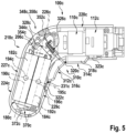
- FIG. 4 to 33 Another exemplary embodiment is shown.
- the exemplary embodiment of Figures 4 to 33 is followed by the letter c.
- the further embodiment of the Figures 4 to 33 differs from the previous exemplary embodiments at least essentially by a design of a drive module 100c and an attachment module 400c.
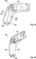
- Figure 4 shows a drive module 100c.
- the drive module 100c is part of a tool module system 10c.
- the tool module system 10c is designed as a kitchen tool module system 12c.
- the tool module system 10c is designed as a hand tool module system.
- the tool module system 10c is designed as a machine tool system.
- the tool module system 10c is designed as a power tool module system.
- the tool module system 10c is designed as a portable tool module system.
- the tool module system 10c is designed as a hand-held tool module system.
- the tool module system 10c is intended for kitchen use.
- the tool module system 10c is intended for use in a living and/or dining area.
- the tool module system 10c is intended for manual use.
- the tool module system 10c has the drive module 100c.
- the tool module system 10c has at least one attachment module 400c, 480c.
- the at least one attachment module 400c, 480c can be coupled to the drive module 100c.
- the tool module system 10c has a plurality of attachment modules 400c, 480c.
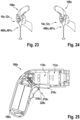
- a first attachment module 400c of the tool module system 10c is in Figure 33 shown.
- the first attachment module 400c is designed as a first tool module 401c.
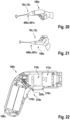
- a second attachment module 480c of the tool module system 10c is in the Figures 20, 21 , 23 and 24 shown.
- the second attachment module 480c is designed as a second tool module 481c.
- the attachment modules 400c, 480c can be designed as mixer attachments, as stirring attachments, as frother attachments, as planing and/or grating attachments, as chopper attachments and/or as mill attachments.
- the drive module 100c is designed as a portable drive module.
- the drive module 100c is designed as a hand-held drive module.
- the drive module 100c has a mass of at most 1000 g, in particular of at most 700 g, advantageously at most 500 g and particularly advantageously at most 350 g.
- the drive module 100c has an in Figure 14 apparent maximum extension 108c of at most 25 cm, in particular at most 22 cm, advantageously at most 20 cm and particularly advantageously at most 19 cm.
- the drive module 100c has a maximum extension 108c of approximately 18.5 cm.
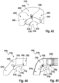
- the drive module 100c can be grasped in a first gripping position.
- the first gripping position is in Figure 20 shown.
- the first gripping position is designed as a pistol grip.
- the drive module 100c can be grasped in a further first gripping position.
- the other first gripping position is in Figure 21 shown.
- the further first gripping position is designed as a reverse pistol grip.
- the drive module 100c can be grasped in a second gripping position.
- the second gripping position is shown in Figure 23.
- the second gripping position is designed as a bar handle, in particular a hand blender handle.
- the drive module 100c can be grasped in a further second gripping position.
- the other second gripping position is in Figure 24 shown.
- the further second gripping position is designed as an inverted bar handle, in particular an inverted hand blender handle.
- the drive module 100c has a drive unit 110c.
- the drive unit 110c is in Figure 4 shown.
- the drive unit 110c is designed as an electrical machine.
- the drive unit 110c is designed as an electric motor.
- the drive unit 110c has a rotor.
- the drive unit 110c has a stator.
- the drive unit 110c is intended for a rotational drive of a drive shaft.
- the drive shaft is rotatably mounted about a rotation axis 124c.
- the drive unit 110c has a plurality of operating functions.
- a first of the operating functions is designed as a counterclockwise rotation function. When the first operating function is activated, the drive unit 110c is intended to move the drive shaft counterclockwise, viewed in the output direction. At least one further first of the operating functions is designed as a clockwise rotation function. When another first operating function is activated, the drive unit 110c is intended to move the drive shaft clockwise, viewed in the output direction.
- a second of the operating functions is designed as an accelerator function.
- the drive unit 110c When the second operating function is activated, the drive unit 110c is intended to move the drive shaft at a speed that can be variably controlled by a user.
- Another second of the operating functions is designed as a soft start function.
- the drive unit 110c When a further second operating function is activated, the drive unit 110c is intended to move the drive shaft at a speed that can be variably controlled by the user.
- the soft start function is activated, the drive unit 110c is intended to keep an angular acceleration of the drive shaft below a positive limit, in particular in the event of a rapid increase in speed specified by the user.
- the drive unit 110c When the soft start function is activated, the drive unit 110c is intended to slowly accelerate the drive shaft up to a speed specified by the user.
- An additional second one of the operating functions is designed as a fixed speed function. When the additional second operating function is activated, the drive unit 110c is intended to move the drive shaft at a constant speed,
- a third of the operating functions is designed as a continuous speed function.
- the drive unit 110c is intended to move the drive shaft at an unmodulated speed.
- Another third of the operating functions is designed as an alternating speed function.
- the drive unit 110c is intended to continuously switch between the left-hand running function and the right-hand running function, in particular by deactivating the pure left-hand running function and the pure right-hand running function.
- An additional third of the operating functions is designed as a pulsating speed function.
- the drive unit 110c is intended to move the drive shaft at a speed that continuously changes between a minimum value, in particular designed as zero, and a maximum value that can be determined by a user.
- Another additional third of the operating functions is designed as a time-dependent speed function.
- Drive unit 110c is intended to move the drive shaft with a predetermined, time-repeated speed curve.
- a fourth of the operating functions is designed as a full torque function.
- the drive unit 110c is intended to move the drive shaft with a maximum torque.
- Another fourth of the operating functions is designed as a partial torque function.
- the drive unit 110c is intended to move the drive shaft with a defined torque value, in particular different from a maximum value.
- the drive unit 110c has at least two operating modes.
- the drive unit 110c has more than two operating modes.
- Each of the operating modes is composed of a combination of several of the operating functions.
- Each of the operating modes is composed of a combination of at least two of the operating functions.
- Availability of the operating modes depends on a design and/or function of an attachment module coupled to the drive module 100c.
- a first of the operating modes is in a coupled state of the drive module 100c and one in Figure 33 shown, designed as a screwdriver module, in particular a screwdriver module, attachment module 400c is available.
- the first operating mode the first operating function and the second operating function are activated.
- Another first of the operating modes is available in the coupled state of the drive module 100c and the attachment module designed as a screwdriver module.
- the further first operating mode the further first operating function and the second operating function are activated.
- a second of the operating modes is available in a coupled state of the drive module 100c and an attachment module, not shown in detail, designed as a chopper module, in particular a herb chopper module.
- the further first operating function and the additional second operating function are activated.
- a further second operating mode is available in the coupled state of the drive module 100c and the attachment module designed as a chopper module.
- the further first operating function and the additional second operating function are activated.
- a speed is higher than in the second operating mode.
- An additional second operating mode is available in the coupled state of the drive module 100c and the attachment module designed as a chopper module. In the additional second operating mode, the additional first operating function and the additional third operating function are activated.
- a third of the operating modes is available in a coupled state of the drive module 100c and an attachment module, not shown in detail, designed as a mill module, in particular a spice mill module.
- the further first operating function and the additional second operating function are activated.
- a fourth of the operating modes is available in a coupled state of the drive module 100c and an attachment module (not shown in detail) designed as a planing and/or grating module, in particular a cheese grater module.
- the first operating function and the additional second operating function are activated.
- a further fourth operating mode is available in the coupled state of the drive module 100c and the attachment module designed as a planing and/or grating module. In the further fourth operating mode, the further first operating function and the additional second operating function are activated.
- a fifth of the operating modes is in a coupled state of the drive module 100c and one in the Figures 20, 21 , 23 and 24 shown, designed as a frother module, in particular a milk frother module, top module 480c is available.
- the further first operating function, the further second operating function and the additional second operating function are activated.
- a further fifth operating mode is available in the coupled state of the drive module 100c and the attachment module designed as a frother module.
- the further first operating function, the further second operating function and the additional second operating function are activated.
- a speed is higher than in the fifth operating mode.
- a sixth of the operating modes is available in a coupled state of the drive module 100c and an attachment module, not shown in detail, designed as a press module, in particular a citrus press module.
- the further first operating function and the additional second operating function are activated.
- the drive unit 110c could have the operating modes listed in the first table below, depending on coupled add-on modules.
- the operating functions listed in the first table are always combined with the second operating function.
- a second line of the first table should be understood as "A seventh operating mode, in particular a screwing-in operating mode, the operating modes are available in a coupled state of the drive module 100c and an attachment module designed as a screwdriver module.
- the further first operating function and the second operating function activated.
- the sixteenth operating mode, the seventeenth operating mode and the eighteenth operating mode are designed as successive operating modes.
- the operating functions of the drive unit 110c are deactivated.
- the drive unit 110c stands still.
- the drive unit 110c is intended to reset a pressing element, in particular a press cone, of an attachment module designed as a press attachment, in particular a lemon press attachment.
- the drive unit 110c could have the operating modes listed in the second table below, depending on coupled add-on modules.
- the operating functions listed in the second table are always combined with the additional second operating function.
- a second line of the second table should be understood as "A nineteenth operating mode, in particular a slow screwing-in operating mode, the operating modes are available in a coupled state of the drive module 100c and an attachment module designed as a screwdriver module.
- the nineteenth operating mode the further first operating function and the additional second operating function is activated.”
- the drive unit 110c has a higher speed than in a corresponding operating state with the suffix "slow”.
- the thirty-seventh operating mode and/or the thirty-eighth operating mode, the thirty-ninth operating mode and the fortieth operating mode and/or the forty-first operating mode are designed as successive operating modes.
- the thirty-ninth operating mode the operating functions of the drive unit 110c are disabled.
- the drive unit 110c stands still.
- the drive unit 110c is intended to reset a pressing element, in particular a press cone, of an attachment module designed as a press attachment, in particular a lemon press attachment.
- the drive unit 110c is intended to to reset a pressing element, in particular a press cone, of an attachment module designed as a press attachment, in particular a lemon press attachment.
- the drive module 100c has an in Figure 4 Gear unit 112c shown.
- the gear unit 112c is arranged coaxially with the drive unit 110c.
- the gear unit 112c is arranged coaxially with the drive shaft.
- the gear unit 112c is arranged coaxially with the rotation axis 124c.
- the transmission unit 112c is connected downstream of the drive unit 110c in the torque flow.
- the transmission unit 112c has a gear transmission.
- the gear transmission is designed as a gear transmission.
- the gear transmission is designed as a spur gear.
- the gear train is designed as a planetary gear train.
- the gear unit 112c has a plurality of gear elements 116c, only a part of which is provided with reference numbers for the sake of clarity.
- the gear elements 116c include shafts and wheels, in particular gears and preferably spur gears.
- the gear unit 112c has a gear housing 114c.
- the gear housing 114c encloses the gear elements 116c.
- a gear unit can be designed as a crank gear, as a cam gear, as a roller gear and/or as a locking gear.
- the gear unit 112c is intended to change the speed.
- the gear unit 112c is intended to change the torque.
- the gear unit 112c is intended to translate a speed of the drive shaft to a speed of a main output shaft 118c.
- the transmission unit 112c is intended to transmit torque from the drive shaft to the main output shaft 118c.
- a gear unit can be provided to change a rotation axis and/or a gear gear can be designed as a bevel gear.
- the drive module 100c has the main output shaft 118c.
- the main output shaft 118c is arranged coaxially with the drive unit 110c.
- the main output shaft 118c is arranged coaxially with the input shaft.
- the main output shaft 118c is arranged coaxially with the transmission unit 112c.
- the main output shaft 118c is rotatably mounted about the rotation axis 120c.
- the main output shaft 118c is connected downstream of the drive unit 110c in the torque flow.
- the main output shaft 118c is connected downstream of the transmission unit 112c in the torque flow.
- the main output shaft 118c has a recess 120c.
- An output-side end of the main output shaft 118c has the recess 120c.
- the recess 120c is designed as a hexagonal recess.
- the recess 120c has a hexagonal cross section.
- the recess 120c is intended to accommodate a shaft.
- the drive module 100c has a main board 204c.
- the main board 204c is in the Figures 4 to 10 shown.
- the main board 204c has an in Figure 7 visible main extension plane 206c, which forms an angle of at most 60 ° with a main extension plane 102c of the drive module 100c.
- the main extension plane 206c of the main board 204c and the main extension plane 102c of the drive module 100c are arranged parallel to one another.
- the main extension plane 206c of the main board 204c and the main extension plane 102c of the drive module 100c are arranged at a distance from one another.
- the main extension plane 206c of the main board 204c and the main extension plane 102c of the drive module 100c are at a distance of at least 5 mm.
- the main extension plane 206c of the main board 204c and the main extension plane 102c of the drive module 100c are at a maximum distance of 15 mm.
- the main board 204c has two sections 208c, 210c.
- the sections 208c, 210c are formed in one piece.
- the main board 204c has a first section 208c.
- the first section 208c essentially has the shape of a rectangle when viewed perpendicular to the main extension plane 206c of the main board 204c.
- the main board 204c has a second section 210c.
- the second section 210c viewed perpendicular to the main extension plane 206c of the main board 204c, essentially has the shape of a triangle, in particular a right-angled triangle.
- the second section 210c borders with a hypotenuse on a short side edge of the first section 208c.
- a particularly geometric center of gravity of the second section 210c is arranged closer to the drive unit 110c than a particularly geometric center of gravity of the first section 208c.
- the motherboard 204c includes three interfaces 212c, 214c, 216c.
- the interfaces 212c, 214c, 216c each have an interface opening.
- the interfaces 212c, 214c, 216c each have a conductor contact.
- the interfaces 212c, 214c, 216c are designed as cable lugs.
- a first interface 212c of the interfaces 212c, 214c, 216c is arranged on a side of the first subsection 208c facing the second subsection 210c.
- a second interface 214c of the interfaces 212c, 214c, 216c is arranged on a side of the first subsection 208c facing the second subsection 210c.
- a third interface 216c of the interfaces 212c, 214c, 216c is arranged on a side of the first subsection 208c facing away from the second subsection 210c.
- a motherboard could have one of three different numbers of interfaces.
- the main board 204c can have at least part of an electronics unit 168c, a reception and/or communication unit 176c and/or a storage unit 178c.
- the main board 204c includes a plurality of electronic components and/or assemblies, for example conductor tracks, capacitors, circuits, memory components and/or computing components, in particular microchips.
- the electronic components and/or assemblies have at least one signal transmission, energy storage, data storage, control, regulation and/or calculation function.
- the drive module 100c has an energy storage unit 180c.
- the energy storage unit 180c is in the Figures 4 to 10 shown.
- the energy storage unit 180c is designed as an electrical energy storage unit.
- the energy storage unit 180c is designed as a rechargeable energy storage unit.
- the energy storage unit 180c is designed as a battery unit, in particular a lithium-ion battery unit.
- the energy storage unit 180c is intended to supply at least the drive unit 110c with energy, in particular electrical energy.
- the energy storage unit 180c has a plurality of energy storage cells 182c, 184c.
- the energy storage unit 180c includes two energy storage cells 182c, 184c.
- the energy storage unit 180c has exactly two energy storage cells 182c, 184c.
- an energy storage unit could also have more than two energy storage cells.
- the energy storage unit 180c includes a first energy storage cell 182c with a first center of gravity 194c, in particular a first center of mass.
- the first energy storage cell 182c essentially has a shape of a cylinder.
- the first energy storage cell 182c is designed as an electrical energy storage cell.
- the first energy storage cell 182c is designed as a rechargeable energy storage cell.
- the first energy storage cell 182c is designed as a battery cell, in particular a lithium-ion battery cell.
- the energy storage unit 180c includes a second energy storage cell 184c with a second center of gravity 196c, in particular a second center of mass.
- the second energy storage cell 184c is designed as an electrical energy storage cell.
- the second energy storage cell 184c is designed as a rechargeable energy storage cell.
- the second energy storage cell 184c is designed as a battery cell, in particular a lithium-ion battery cell.
- the second energy storage cell 184c essentially has a shape of a cylinder.
- a longitudinal extension axis 192c of the second energy storage cell 184c is arranged parallel to a longitudinal extension axis 190c of the first energy storage cell 182c.
- the energy storage cells 182c, 184c include three plug contacts 198c, 200c, 202c, which are in Figure 10 are shown.
- the three plug contacts 198c, 200c, 202c correspond to the interfaces 212c, 214c, 216c.
- the first energy storage cell 182c includes a first plug contact 198c of the plug contacts 198c, 200c, 202c.
- the first plug contact 198c corresponds to the first interface 212c.
- the first plug contact 198c and the first interface 212c are provided to form a first plug connection.
- the second energy storage cell 184c includes a second plug contact 200c of the plug contacts 198c, 200c, 202c.
- the second plug contact 200c corresponds to the second interface 214c.
- the second plug contact 200c and the second interface 214c are provided to form a second plug connection.
- the first energy storage cell 182c and the second energy storage cell 184c include a common third plug contact 202c of the plug contacts 198c, 200c, 202c.
- the third plug contact 202c is arranged at an end of the first energy storage cell 182c opposite the first plug contact 198c.
- the third plug contact 202c is arranged at an end of the second energy storage cell 182c opposite the second plug contact 200c.
- the third plug contact 202c corresponds to the third interface 216c.
- the third plug contact 202c and the third interface 216c are provided to form a third plug connection.
- FIG. 5 , 6 and 7 is a center of gravity axis 195c through the first center of gravity 194c of the first energy storage cell 182c and through the second center of gravity 196c of the second energy storage cell 184c.
- the center of gravity axis 195c forms an angle of at most 60° with a main extension plane 102c of the drive module 100c.
- the center of gravity axis 195c is arranged parallel to the main extension plane 102c of the drive module 100c.
- the center of gravity axis 195c is arranged at a distance from the main extension plane 102c of the drive module 100c.
- the center of gravity axis 195c is at a distance of more than 1 mm from the main extension plane 102c of the drive module 100c.
- the center of gravity axis 195c is at a distance of less than 3 mm from the main extension plane 102c of the drive module 100c.
- the center of gravity axis 195c is at a distance of approximately 2 mm from the main extension plane 102c of the drive module 100c.
- a maximum number of energy storage cells 182c, 184c of the energy storage unit 180c arranged one behind the other perpendicular to the main extension plane 102c of the drive module 100c is one.
- the first energy storage cell 182c and the second energy storage cell 184c are arranged without overlap when viewed perpendicular to the main extension plane 102c of the drive module 100c.
- the first energy storage cell 182c and the second energy storage cell 184c can be plugged onto the main board 204c independently of one another.
- a maximum number of energy storage cells 182c, 184c of the energy storage unit 180c arranged one behind the other in the main extension plane 102c is two.
- the first energy storage cell 182c and the second energy storage cell 182c are arranged one behind the other in the main extension plane 102c.
- the maximum number of energy storage cells arranged one behind the other perpendicular to the main extension plane 102c of the drive module 100c 182c, 184c is less than the maximum number of energy storage cells 182c, 184c arranged one behind the other in the main extension plane 102c.
- the drive module 100c has a housing unit 218c.
- the housing unit 218c is in the Figures 11 to 19 shown in more detail.
- the housing unit 218c is pistol-shaped.
- the housing unit 218c is designed in several parts.
- the housing unit 218c consists at least partially of a plastic, in particular a thermoplastic and preferably of acrylonitrile-butadiene-styrene copolymers (ABS).
- ABS acrylonitrile-butadiene-styrene copolymers
- the housing unit 218c consists at least largely of a plastic, in particular of a thermoplastic and preferably of ABS.
- the housing unit 218c has an in. parallel to the axis of rotation 124c Figure 14 shown maximum extension 228c of at most 18 cm.
- the housing unit 218c has a maximum extension 228c of approximately 15.3 cm parallel to the axis of rotation 124c.
- the housing unit 218c has a maximum extension 230c of at most 15 cm perpendicular to the axis of rotation 124c.
- the housing unit 218c has a maximum extension 230c of approximately 12.1 cm perpendicular to the axis of rotation 124c.
- the housing unit 218c includes a drive housing section 220c.
- the drive housing portion 220c essentially has a shape of a hollow cylinder.
- a cross section through the drive housing section 220c perpendicular to a longitudinal extension axis 222c of the drive housing section 220c essentially has the shape of a circular ring.
- a longitudinal extent of the drive housing section 220c is larger than a mean diameter of the drive housing section 220c.
- a longitudinal extent of the drive housing section 220c is less than twice the diameter of the drive housing section 220c.
- extension 106c of the drive housing section 220c perpendicular to the main extension plane 102c of the drive module 100c is at most 55 mm.
- the extension 106c of the drive housing section 220c perpendicular to the main extension plane 102c of the drive module 100c is approximately 55 mm.
- the drive housing section 220c encloses the in Figure 4 shown drive unit 110c.
- a longitudinal extension axis 222c of the drive housing section 220c is arranged substantially parallel to the rotation axis 124c.
- a cavity 221c is arranged between the drive housing section 220c and the drive unit 110c.
- the drive housing section 220c encloses the in Figure 4 shown gear unit 112c.
- the drive housing section 220c is arranged substantially coaxially with the gear unit 112c.
- the housing unit 218c includes a handle housing portion 224c.
- the handle housing section 224c tapers continuously along a longitudinal extension axis 226c of the handle housing section 224c towards a free end 225c of the handle housing section 224c.
- the handle housing section 224c tapers continuously towards the free end 225c when viewed in the center of gravity axis 195c.
- a cross section through the handle housing portion 224c perpendicular to the longitudinal extension axis 226c of the handle housing portion 224c has a substantially oval ring shape.
- the handle housing section 224c has an in. perpendicular to the main extension plane 102c of the drive module 100c Figure 12 shown maximum extension 104c of at most 44 mm.
- the handle housing section 224c has an extension 104c of approximately 35 mm perpendicular to the main extension plane 102c of the drive module 100c.
- the handle housing section 224c has an in. parallel to the center of gravity axis 195c Figure 14 shown maximum extension 232c of at most 60 mm.
- the handle housing section 224c has a maximum extension 232c of approximately 45 mm parallel to the center of gravity axis 195c.
- the maximum extension 104c of the handle housing section 224c perpendicular to the main extension plane 102c of the drive module 100c is less than the maximum extension 232c of the handle housing section 224c parallel to the center of gravity axis 195c.
- the handle housing section 224c encloses the in Figure 4 shown main board 204c to a large extent.
- the handle housing section 224c largely encloses the energy storage unit 180c.
- An inner narrow side 229c of the handle housing section 224c is separated from the second energy storage cell 184c by a cavity 231c.
- the longitudinal extension axis 226c of the handle housing section 224c is arranged at least substantially parallel to the longitudinal extension axis 190c of the first energy storage cell 182c.
- the longitudinal extension axis 226c of the handle housing section 224c is arranged substantially parallel to the longitudinal extension axis 192c of the second energy storage cell 184c.
- the longitudinal extension axis 226c of the handle housing section 224c is arranged at least substantially perpendicular to the center of gravity axis 195c.
- the handle housing section 224c is arranged at an angle to the drive housing section 220c.
- An in Figure 14 The interior angle 234c shown between the longitudinal extension axis 222c of the drive housing section 220c and the longitudinal extension axis 226c of the handle housing section 224c is at least 80°.
- the interior angle 234c is at most 170°.
- the interior angle 234c is approximately 110°.
- the drive housing section 220c and the handle housing section 224c span the main extension plane 102c of the drive module 100c.
- a curved transition region 236c is arranged between the handle housing section 224c and the drive housing section 220c.
- the handle housing section 224c and the drive housing section 220c are connected via the transition region 236c.
- One longitudinal end of the handle housing section 224c and the drive housing section 220c borders the transition region 236c.
- the drive housing section 220c and the transition region 236c are partially formed in one piece.
- the handle housing section 224c and the transition region 236c are partially formed in one piece.
- the drive housing section 220c, the transition region 236c and the handle housing section 224c are partially formed in one piece.
- the transition region 236c includes a convexly curved outer area 238c.
- the transition region 236c includes a saddle-shaped curved inner region 240c.
- the housing unit 218c has a base housing 242c.
- the base housing 242c extends over the drive housing portion 220c.
- the base housing 242c extends over the handle housing portion 224c.
- the base case 242c extends over the transition area 236c.
- the base housing 242c consists at least largely of a plastic, in particular a thermoplastic.
- the base housing 242c consists entirely of a plastic, in particular a thermoplastic.
- the base housing 242c is intended to fix functional elements, in particular all functional elements of the drive module 100c.
- the base housing 242c is intended to fix the main board 204c.
- the base housing 242 is intended to fix the drive unit 110c.
- the base housing 242c is intended to fix the gear unit 112c.
- the base housing 242c has a viewing area 248c, 250c.
- the viewing area 248c, 250c is visible in a mounted state of the drive module 100c.
- the viewing area 248c, 250c extends over the drive housing section 220c, in particular in the mounted state of the drive module 100c on an underside of the drive housing section 220c, preferably with respect to the first gripping position.
- the viewing area 248c, 250c extends over the handle housing section 224c, in particular in the mounted state of the drive module 100c on a front side of the handle housing section 224c, which is preferably facing away from a user in the first gripping position.
- the viewing area 248c, 250c extends over the transition area 236c, in particular the interior area 240c of the transition area 236c.
- the base housing 242c has a support area 252c, 254c.
- the carrier area 252c, 254c is covered in the mounted state of the drive module 100c.
- the carrier region 252c, 254c extends over the drive housing section 220c, in particular in the mounted state of the drive module 100c on an upper side of the drive housing section 220c, preferably with respect to the first gripping position.
- the carrier region 252c, 254c extends over the handle housing section 224c, in particular in the mounted state of the drive module 100c on a rear side of the handle housing section 224c, preferably facing a user in the first gripping position.
- the carrier region 252c, 254c extends over the transition region 236c, in particular the outer area 238c of the transition region 236c.
- the base housing 242c has a housing stage 256c, 258c.
- the viewing area 248c, 250c and the carrier area 252c, 254c are separated from each other by the housing step 256c, 258c.
- the viewing area 248c, 250c rises on the housing step 256c, 258c relative to the carrier area 252c, 254c.
- the base housing 242c is designed in several parts.
- the base housing 242c is designed in two parts.
- the base housing 242c includes a first base housing component 244c.
- the first base housing component 244c consists at least largely of a plastic, in particular a thermoplastic.
- the first base housing component 244c consists of a plastic, in particular a thermoplastic.
- the first base housing component 244c is designed as a first half-shell. In the assembled state of the drive module 100c, the first base housing component 244c is approximately limited by the main extension plane 102c of the drive module 100c.
- the first base housing component 244c has a plurality of first positive and/or frictional locking elements 276c.
- the first positive and/or frictional elements 276c are in Figure 29 shown.
- the first positive and/or frictional engagement elements 276c are arranged on a housing edge between a concave housing inside and a convex housing outside of the first base housing component 244c.
- the first base housing component 244c has a first viewing area 248c.
- the first base housing component 244c has a first support region 252c.
- the first viewing area 248c and the first carrier area 252c are separated from one another by a first housing stage 256c.
- the first viewing area 248c rises on the first housing stage 256c relative to the first support area 252c.
- the first base housing component 244c has a plurality of receiving elements 260c, 262c, 264c, 266c.
- the first base housing component 244c has four receiving elements 260c, 262c, 264c, 266c.
- a first receiving element 260c of the receiving elements 260c, 262c, 264c, 266c is part of a last third of the handle housing section 224c comprising the end 225c.
- the first receiving element 260c is part of the first viewing area 248c.
- a second receiving element 262c of the receiving elements 260c, 262c, 264c, 266c is part of the Outer area 238c of the transition area 236c.
- the second receiving element 262c is part of the first support area 252c.
- a third receiving element 264c of the receiving elements 260c, 262c, 264c, 266c is part of a half of the drive housing section 220c facing away from the transition region 236c.
- the third receiving element 266c is part of the first viewing area 248c.
- a fourth receiving element 266c of the receiving elements 260c, 262c, 264c, 266c is part of the half of the drive housing section 220c facing away from the transition region 236c.
- the fourth receiving element 266c is part of the first support area 252c.
- the receiving elements 260c, 262c, 264c, 266c are essentially designed to have the same shape and function.
- the first receiving element 260c is described in more detail below as an example.
- the features of the first receiving element 260c apply analogously to the second receiving element 262c, to the third receiving element 264c and to the fourth receiving element 266c.
- the first receiving element 260c is designed as a first screw dome.
- the first receiving element 260c is embedded in a housing shell of the first base housing component 244c.
- the first receiving element 260c is intended to receive a first connecting element, in particular a bolt and/or a screw.
- the first receiving element 260c encloses a first recess, which essentially has the shape of a circular cylinder.
- the first recess is accessible from an inside of the housing of the first base housing component 244c, in particular in an unassembled state of the first base housing component 244c.
- the base housing 242c includes a second base housing component 246c.
- the second base housing component 246c consists at least largely of a plastic, in particular a thermoplastic.
- the second base housing component 246c consists of a plastic, in particular a thermoplastic.
- the second base housing component 246c is designed as a second half-shell. In the assembled state of the drive module 100c, the second base housing component 246c is approximately limited by the main extension plane 102c of the drive module 100c.
- the first base housing component 244c and the second base housing component 246c are designed to be essentially mirror-symmetrical to one another.
- the second base housing component 246c has a plurality of second positive and/or frictional locking elements, not shown in detail.
- the second positive and/or frictional engagement elements are arranged on a housing edge between a concave housing inside and a convex housing outside of the second base housing component 246c.
- the second positive and/or frictional elements correspond to the first positive and/or frictional elements 276c.
- the first positive and/or frictional engagement elements 276c and the second positive and/or frictional engagement elements are provided for a frictional and/or positive connection of the first base housing component 244c and the second base housing component 246c.
- the second base housing component 246c has a second viewing area 250c.
- the second base housing component 246c has a second support region 254c.
- the second viewing area 250c and the second carrier area 254c are separated from one another by a second housing stage 258c.
- the second viewing area 250c rises on the second housing stage 258c relative to the second support area 254c.
- the second base housing component 246c has a plurality of further receiving elements 268c, 270c, 272c, 274c.
- the second base housing component 246c has four further receiving elements 268c, 270c, 272c, 274c.
- a first further receiving element 268c of the further receiving elements 268c, 270c, 272c, 274c is part of the last third of the handle housing section 224c comprising the end 225c.
- the first further receiving element 268c is part of the second viewing area 250c.
- a second further receiving element 270c of the further receiving elements 268c, 270c, 272c, 274c is part of the outer region 238c of the transition region 236c.
- the second further receiving element 270c is part of the second support area 254c.
- a third further receiving element 272c of the receiving elements 268c, 270c, 272c, 274c is part of a half of the drive housing section 220c facing away from the transition region 236c.
- the third additional receiving element 272c is part of the second viewing area 250c.
- a fourth further receiving element 274c of the receiving elements 268c, 270c, 272c, 274c is part of the half of the drive housing section 220c facing away from the transition region 236c.
- the fourth further receiving element 274c is part of the second support area 254c.
- the further receiving elements 268c, 270c, 272c, 274c are essentially designed to have the same shape and function.
- the first further receiving element 268c is described in more detail below as an example.
- the features of the first further receiving element 268c apply analogously to the second further receiving element 270c, to the third further receiving element 272c and to the fourth further receiving element 274c.
- the first further receiving element 268c is designed as a first further screw dome.
- the first further receiving element 268c is embedded in a housing shell of the second base housing component 246c.
- the first further receiving element 268c is intended to receive the first connecting element, in particular a first screw element.
- the first further receiving element 268c corresponds to the first receiving element 260c.
- the first further receiving element 268c encloses a first further recess, which essentially has a circular cylindrical shape.
- the first further recess is accessible from an inside of the housing of the second base housing component 246c, in particular in the unassembled state of the second base housing component 246c.
- the first further recess is accessible from an outside of the housing of the second base housing component 246c, in particular in the unassembled state of the second base housing component 246c.
- the first connecting element can be inserted through the first further recess of the first further receiving element 268c into the first recess of the first receiving element 260c.
- the first viewing area 248c and the second viewing area 250c form the viewing area 248c, 250c of the base housing 242c in a connected state of the first base housing component 244c and the second base housing component 246c.
- the first carrier region 252c and the second carrier region 254c form the carrier region 252c, 254c of the base housing 242c in a connected state of the first base housing component 244c and the second base housing component 246c.
- the first housing stage 256c and the second housing stage 258c form the housing stage 256c, 258c of the base housing 242c in a connected state of the first base housing component 244c and the second base housing component 246c.
- the base housing 242c has a first cover unit 278c.
- the first panel unit 278c is in the Figures 11 and 19 shown.
- the first cladding unit 278c is designed in one piece, in particular in one piece.
- the first cladding unit 278c is designed as a first plug.
- the first cladding unit 278c is intended to clad and/or cover the third further receiving element 272c.
- the first cladding unit 278c is intended to protect the third additional receiving element 272c from contamination.
- the first cladding unit 278c includes a first base body 280c.
- the first cladding unit 278c includes a first cover element 282c.
- the first cover element 282c has a first curved viewing surface. The curvature of the first viewing surface is adapted to a curvature of the second base housing component 246c in a surrounding area of the first further receiving element 268c.
- the first cladding unit 278c includes a first guide element 284c.
- the first guide element 284c is designed as a guide rib.
- the first guide element 284c is designed as a mounting rib.
- the first guide element 284c is intended to guide the first cladding unit 278c in a corresponding housing recess during assembly on the first further receiving element 268c.
- the base housing 242c has a second cover unit 286c.
- the second trim unit 286c is in Figure 11 shown.
- the second cladding unit 286c essentially corresponds to the first cladding unit 278c.
- the second cladding unit 286c is intended to clad and/or cover the first further receiving element 268c.
- the second cladding unit 286c is intended to protect the first further receiving element 268c from contamination.
- the second cladding unit 286c has dimensions that differ from the first cladding unit 278c.
- a second curved viewing surface of a second cover element of the second cladding unit is adapted to a curvature of the second base housing component 246c in a surrounding area of the third further receiving element 272c.
- the base housing 242c has a plurality of recesses 288c, 290c, 292c.
- the recesses 288c, 290c, 292c are in Figure 17 shown.
- the base housing 242c has three recesses 288c, 290c, 292c.
- the recesses 288c, 290c, 292c are embedded in the carrier area 252c, 254c of the base housing 242c.
- a first recess 288c of the recesses 288c, 290c, 292c is embedded in the first base housing component 244c.
- the first recess 288c is arranged in a last quarter of the drive housing section 220c facing away from the transition region 236c.
- a second recess 290c of the recesses 288c, 290c, 292c is embedded in the second base housing component 246c.
- the second recess 290c is arranged in the last quarter of the drive housing section 220c facing away from the transition region 236c.
- a third recess 292c of the recesses 288c, 290c, 292c is half embedded in the first base housing component 244c and half in the second base housing component 246c.
- the third recess 292c is arranged at the end 225c of the handle housing section 224c.
- the drive module 100c has two visible components 294c, 350c.
- the two visible components 294c, 350c are designed as metallic-coated visible components.
- the two visible components 294c, 350c are designed as metal-coated visible components.
- the two visible components 294c, 350c are designed as galvano-coated visible components.
- the drive module 100c has a first visible component 294c.
- the first visible component is in Figure 18 shown.
- the first visible component 294c is designed as a metallic-coated visible component.
- the first visible component 294c is designed as a metal-coated visible component.
- the first visible component 294c is designed as a galvano-coated visible component.
- the housing unit 218c has a first visible component 294c.
- the first visible component 294c is designed as a housing attachment. In an assembled state, the first visible component 294c covers the carrier area 252c, 254c of the base housing 242c.
- the first visible component 294c and the visible area 248c, 250c of the base housing 242c form a large part of a visible surface of the drive module 100c.
- a visible surface of the first visible component 294c corresponds at least 30% of the visible area of the drive module 100c.
- the visible area of the first visible component 294c corresponds to a maximum of 90% of the visible area of the drive module 100c.
- the first visible component 294c covers at least one housing connection in an assembled state.
- the first visible component 294c covers the second further receiving element 270c. In the assembled state, the first visible component 294c covers the fourth further receiving element 274c.
- the first visible component 294c is intended to protect the second further receiving element 270c from contamination.
- the first visible component 294c is intended to protect the fourth further receiving element 274c from contamination.
- the first visible component 294c has a base body.
- the base body of the first visible component 294c consists of a plastic, in particular a thermoplastic and preferably ABS.
- the first visible component 294c has at least one metallic coating, in particular metal coating.
- the first visible component 294c has a plurality of metal coatings, in particular galvanic coatings.
- the first visible component 294c has a matt surface.
- the first visible component 294c has, for example, a rose gold surface.
- a visible component could have a shiny and/or a further roughened, for example brushed, surface structure and/or a surface in silver, in dark gray-silver, in copper and/or in other metallic colors. This can create an advantageous visual impression.
- the first visible component 294c has several sections in terms of a shape.
- the first visible component 294c has a first section 296c.
- the first section 296c has a horseshoe-shaped cross section.
- the first section 296c forms part of the drive housing section 220c, in particular in the assembled state of the first visible component 294c.
- An end of the first visible component 294c facing away from the transition region 236c in the assembled state of the first visible component 294c has a recess 302c.
- the first visible component 294c has a second section 298c.
- the second section 298c is arranged at an angle to the first section 296c.
- a longitudinal extension axis of the first section 296c and a longitudinal extension axis of the second section 298c form an angle of at least 80°.
- the longitudinal axis of extension of the first section 296c and the longitudinal axis of extension of the second section 298c enclose an angle of at most 170°.
- the longitudinal axis of the first section 296c and the longitudinal axis of the second section 298c form an angle of approximately 107°.
- the second section 298c forms part of the handle housing section 224c, in particular in the assembled state of the first visible component 294c.
- the first visible component 294c has a transition section 297c between the first section 296c and the second section 298c.
- the transition section 297c forms part of the transition region 236c of the housing unit 218c.
- the transition section 297c forms part of the outer region 238c of the transition region 236c.
- the transition section 297c has a first opening.
- the transition section 297c has a second opening.
- the first visible component 294c has a nose 300c.
- the nose 300c adjoins one end of the second section 298c.
- the nose 300c closes off the first visible component 294c.
- the nose 300c is curved.
- a tip of the nose 300c forms the end 225c of the handle housing section 224c in the assembled state of the first visible component 294c.
- the first visible component 294c is designed as a clip component.
- the first visible component 294c is designed as a final clip component.
- the first visible component 294c is intended for a clip connection to the base housing 242c.
- the first visible component 294c has a fixing unit 303c.
- the fixing unit 303c is intended to fix the first visible component 294c on the base housing 242c.
- the fixing unit 303c includes a first fixing element 304c.
- the first fixing element 304c is designed as a latching element, in particular latching hook.
- the first fixing element 304c is arranged on the first section 296c.
- the first fixing element 304c is intended to fit into the first recess 288c grab, especially snap into place.
- the fixing unit 303c includes a second fixing element 306c.
- the second fixing element 306c is designed as a latching element, in particular latching hook.
- the second fixing element 306c is arranged on the first section 296c.
- the second fixing element 306c is intended to engage, in particular to snap into, the second recess 290c.
- the fixing unit 303c includes a third fixing element 308c.
- the third fixing element 308c is designed as a latching element, in particular latching hook.
- the third fixing element 308c is arranged on the nose 300c.
- the third fixing element 308c is intended to engage, in particular to snap into, the third recess 292c.
- the drive module 100c has two actuation units 310c, 348c.
- the drive module 100c has a first actuation unit 310c.
- the first actuation unit 310c is, for example, in the Figures 5 and 17 shown.
- the first actuation unit 310c is designed as a pressure actuation unit.
- the first actuation unit 310c is intended for manual adjustment of at least one drive parameter of the drive unit 110c.
- the drive parameter is at least designed as a speed. Alternatively or additionally, a drive parameter could be designed as a torque, as an operating function and/or as an operating mode.
- the first actuation unit 310c is partially arranged in the curved transition region 236c between the handle housing section 224c and the drive housing section 220c.
- the first actuation unit 310c is arranged in the interior region 240c of the transition region 236c.
- the first actuation unit 310c is partially arranged in the drive housing section 220c.
- the first actuation unit 310c is partially arranged on the underside of the drive housing section 220c.
- the first actuation unit 310c is partially arranged in the handle housing section 224c.
- the first actuation unit 310c is partially arranged on the front of the handle housing section 224c.
- the first actuation unit 310c has two actuation surfaces 312c, 314c.
- the first actuation unit 310c has a first actuation surface 312c.
- the first actuation surface 312c faces in at least one direction a concave shape.
- the first actuation surface 312c has a concave shape when viewed perpendicular to the main extension plane 102c of the drive module 100c.
- the first actuation surface 310c is saddle-shaped.
- the first actuation unit 310c has a second actuation surface 314c.
- the second actuation surface 314c is at least substantially parallel to a longitudinal extension axis 222c of the drive housing section 220c.
- the actuation surfaces 312c, 314c are intended for fundamentally different handling operations.
- the first actuation surface 312c is intended for the first gripping position.
- the first actuation surface 312c is intended for the further first gripping position.
- the first actuation surface 312c is arranged in the first gripping position within index finger reach.
- the first actuation surface 312c is arranged in the further first gripping position within little finger reach.
- the first actuation surface 312c has a longitudinal extent of at least 2 cm.
- the first actuation surface 312c has a transverse extent of at least 1 cm.
- the second actuation surface 314c is intended for the second gripping position.
- the second actuation surface 314c is arranged in the second gripping position within thumb reach.
- the second actuation surface 314c is intended for the further second gripping position.
- the second actuation surface 314c is arranged in the further second gripping position within reach of the index finger.
- the second actuation surface 314c has a longitudinal extent of at least 2 cm.
- the second actuation surface 314c has a transverse extension of at least 1 cm.
- the first actuation unit 310c has a first actuation element 316c.
- the first actuating element 316c is partially arranged in the handle housing section 224c, in particular at one end of the handle housing section 224c.
- the first actuating element 316c is partially arranged in the transition region 236c.
- the first actuating element 316c is embedded in the housing unit 218c.
- the first actuating element 316c is embedded in the base housing 242c.
- the first actuating element 316c is embedded between the first base housing component 244c and the second base housing component 246c.
- the first actuating element 316c is arranged in at least one gripping position within index finger reach.
- the first actuator 316c is the The first gripping position is within reach of the index finger.
- Figure 22 shows the first actuation element 316c in an actuated state.
- the first actuating element 316c is tongue-shaped.
- the first actuation element 316c has the first actuation surface 312c.
- the first actuation surface 312c rises above the housing unit 218c by at least 2 mm.
- the first actuation surface 312c rises from the housing unit 218c by approximately 4 mm.
- the first actuating element 316c is designed as a switch, in particular a pressure switch and/or an accelerator switch. An increasing actuation pressure on the first actuation element 316c causes an increasing speed of the drive unit 110c.
- the first actuation unit 310c has a further first actuation element 318c.
- the further first actuating element 318c is arranged in the drive housing section 220c.
- the further first actuating element 318c is embedded in the housing unit 218c.
- the further first actuating element 318c is embedded in the base housing 242c.
- the further first actuating element 318c is embedded between the first base housing component 244c and the second base housing component 246c.
- the further first actuating element 318c is arranged in at least one gripping position within index finger reach.
- the further first actuating element 318c is arranged in the further second gripping position within reach of the index finger.
- Figure 25 shows the further first actuating element 318c in an actuated state.
- the further first actuating element 318c is tongue-shaped.
- the further first actuation element 318c has the second actuation surface 314c.
- the second actuation surface 314c rises above the housing unit 218c by at least 2 mm.
- the second actuation surface 314c rises from the housing unit 218c by approximately 4 mm.
- a dome-shaped longitudinal end of the first actuation element 316c and a dome-shaped longitudinal end of the further first actuation element 318c are arranged facing each other.
- a flat longitudinal end of the first actuator 316c and a flat longitudinal end of the further first actuating element 318c are arranged facing away from each other.
- the further first actuating element 318c is designed as a switch, in particular a pressure switch and/or an accelerator switch. An increasing actuation pressure on the further first actuation element 318c causes an increasing speed of the drive unit 110c.
- the further first actuation element 318c is redundant to the first actuation element 316c.
- the further first actuating element 318c is functionally redundant to the first actuating element 316c.
- the drive module 100c has a separating element 320c.
- the curved transition region 236c has the separating element 320c.
- the separating element 320c is designed as an elevation of the curved transition region 236c.
- the separating element 320c is designed as a separating rib.
- the separating element 320c is arranged between the first actuating element 316c and the further first actuating element 318c.
- the separating element 320c separates the first actuating element 316c and the further first actuating element 318c from one another.
- Figure 26 shows the first actuation element 316c and the further first actuation element 318c in an actuated state.
- the separating element 320c rises above the first actuation element 316c and above the further first actuation element 318c.
- the separating element 320c makes it more difficult to actuate the first actuation element 316c and/or the further first actuation element 318c.
- the drive module 100c has a switching element 326c.
- the switching element 326c is, for example, in Figure 5 shown.
- the switching element 326c is pin-shaped.
- the switching element 326c is designed as a, in particular spring-loaded, plunger.
- the switching element 326c is mounted movably along a longitudinal axis of the switching element 326c.
- the switching element 326c is Can be equally actuated via the actuation surfaces 312c, 314c of the first actuation unit 310c.
- the actuation surfaces 312c, 314c are functionally redundant.
- the switching element 326c can be actuated equally via the first actuation element 316c and via the further first actuation element 318c.
- the switching element 326c is coupled to the first actuation element 316c and to the further first actuation element 318c.
- the drive module 100c has a spring element 328c.
- the spring element 328c is designed as a compression spring element.
- the spring element 328c is designed as a coil spring.
- a longitudinal axis of extension of the spring element 328c corresponds to a longitudinal axis of extension of the switching element 326c.
- the spring element 328c partially surrounds the switching element 326c.
- the spring element 328c winds around the switching element 326c.
- the spring element 328c is intended to exert a restoring force on the switching element 326c.
- the drive module 100c has an electrical assembly 344c.
- the assembly 344c is arranged perpendicular to the main extension plane 102c of the drive module 100c at an intersection of the longitudinal extension axis 222c of the drive housing section 220c and the longitudinal extension axis 226c of the handle housing section 224c.
- the assembly 344c is designed as a potentiometer.
- the assembly 344c is intended to influence at least one electrical resistance depending on a mechanical movement of the switching element 326c.
- the assembly 344c is intended to convert a mechanical movement of the switching element 326c into an electrical signal, in particular a control signal.
- the switching element 326c In the in Figure 22 shown actuated state of the first actuating element 316c, the switching element 326c is displaced in the direction of the electrical assembly 344c. In the actuated state of the first actuating element 316c, the switching element 326c acts on the electrical assembly 344c. In the in Figure 25 shown actuated state of the further first actuating element 318c, the switching element 326c is displaced in the direction of the electrical assembly 344c. In the actuated state of the further first actuating element 318c, the switching element 326c acts on the electrical assembly 344c.
- the drive module 100c has a leaf spring element 322c.
- the leaf spring element 322c is designed as a spring plate.
- the leaf spring element 322c is intended to exert a restoring force on the first actuating element 316c.
- the leaf spring element 322c is intended to press the first actuating element 316c out of the housing unit 218c.
- the leaf spring element 322c is intended to fix the first actuating element 316c on the housing unit 218c, in particular on the handle housing section 224c.
- the drive module 100c has a further leaf spring element 323c.
- the further leaf spring element 323c is designed as a further spring plate.
- the further leaf spring element 323c is intended to exert a restoring force on the further first actuating element 318c.
- the further leaf spring element 323c is intended to press the further first actuating element 318c out of the housing unit 218c.
- the further leaf spring element 323c is intended to fix the further first actuating element 318c on the housing unit 218c, in particular on the handle housing section 224c.
- the drive module 100c has a second actuation unit 348c.
- the second actuation unit 348c is, for example, in the Figures 27 and 28 shown.
- the second actuation unit 348c is designed as a pressure actuation unit.
- the second actuation unit 348c is intended for manual actuation of the drive unit 110c.
- the second actuation unit 348c has a second actuation element 352c.
- the second actuation element 352c is arranged in the curved transition region 236c.
- the second actuating element 352c is arranged in the outer area 238c of the curved transition region 236c.
- the second Actuating element 352c is embedded in the housing unit 218c.
- the second actuating element 352c is embedded between the first base housing component 244c and the second base housing component 246c.
- the second actuating element 352c is embedded in the first opening of the transition section of the first visible component 294c.
- the second actuating element 352c is arranged in the first gripping position within thumb reach.
- the second actuating element 352c is arranged in the further second gripping position within thumb reach.
- the second actuating element 352c is intended for manual selection of the operating modes.
- the second actuating element 352c essentially has the shape of a circular cylinder.
- the second actuation element 352c has a convex actuation surface 356c.
- the second actuation unit 348c has an additional second actuation element 354c.
- the additional second actuating element 354c is arranged in the curved transition region 236c.
- the additional second actuating element 354c is arranged in the outer area 238c of the transition region 236c.
- the additional second actuating element 354c is embedded in the housing unit 218c.
- the additional second actuating element 354c is embedded between the first base housing component 244c and the second base housing component 246c.
- the additional second actuating element 354c is embedded in the second opening of the transition section of the first visible component 294c.
- the additional second actuating element 354c is arranged in the first gripping position within thumb reach.
- the additional second actuating element 354c is arranged in the further second gripping position within thumb reach.
- the additional second actuating element 354c is provided for manually switching on the drive module 100c.
- the additional second actuating element 354c is provided for manually switching off the drive module 100c.
- the additional second actuating element 354c essentially has the shape of a circular cylinder.
- the additional second actuation element 354c has a convex actuation surface 358c.
- the second actuation unit 348c is designed in one piece.
- the second actuating element 352c and the additional second actuating element 354c are permanently connected.
- the second actuating element 352c and the additional second actuating element 354c are formed in one piece, in particular in one piece.
- the second actuation unit 348c has a connecting element 360c.
- the connecting element 360c is arranged in the transition region 236c.
- the connecting element 360c is arranged in the outer area 238c of the transition region 236c.
- the connecting element 360c is permanently connected to the second actuating element 352c.
- the connecting element 360c and the second actuating element 352c are formed in one piece, in particular in one piece.
- the connecting element 360c is permanently connected to the additional second actuating element 354c.
- the connecting element 360c and the additional second actuating element 354c are formed in one piece, in particular in one piece.
- the connecting element 360c has a first bulge 362c.
- the first bulge 362c is arranged at an end of the connecting element 360c facing the second actuating element 352c.
- the connecting element 360c has a second bulge 364c.
- the second bulge 364c is arranged at an end of the connecting element 360c facing the additional second actuating element 354c.
- the connecting element 360c has a central web 363c.
- the central web 363c connects the first bulge 362c and the second bulge 364c.
- the central web 363c is arranged pivotably.
- the drive module 100c includes a sub-board 346c.
- the sub-board 346c is arranged within the transition region 236c.
- a main extension plane of the secondary board 346c is arranged perpendicular to the main extension plane 206c of the main board 204c.
- the sub-board 346c is coupled to the center bar 363c.
- the sub-board 346c has a first switch 366c.
- the first switch 366c is designed as a pressure switch.
- the first switch 366c is designed as a microswitch.
- the first switch 366c can be actuated by means of the first bulge 362c.
- the first switch 366c can be actuated by means of the second actuating element 352c.
- the sub-board 346c has a second switch 368c.
- the second switch 368c is as a pressure switch educated.
- the second switch 368c is designed as a microswitch.
- the second switch 368c can be actuated by means of the second bulge 364c.
- the second switch 368c can be actuated by means of the additional second actuating element 354c.
- the sub-board 346c is connected to the assembly 344c.
- the assembly 344c is mounted on the sub-board 346c.
- the drive module 100c has a second visible component 350c.
- the second visible component 350c includes the additional second actuating element 354c.
- the second visible component 350c includes the connecting element 360c.
- the second visible component 350c is designed as the second actuation element 352c, as the additional second actuation element 354c and as the connecting element 360c.
- the first visible component 294c encloses the second visible component 350c.
- the second visible component 350c has two partial visible surfaces 355c, 357c that are separate from one another.
- a first partial visible surface 355c of the partial visible surfaces 355c, 357c includes the first actuation surface 356c.
- a second partial visible surface 357c of the partial visible surfaces 355c, 357c includes the second actuation surface 358c.
- the second visible component 350c includes the second actuating element 352c.
- the second visible component 350c is designed as a metallic-coated visible component.
- the second visible component 350c is designed as a metal-coated visible component.
- the second visible component 350c is designed as a galvano-coated visible component.
- the second visible component 350c has a base body.
- the base body of the second visible component 350c consists of a plastic, in particular a thermoplastic and preferably ABS.
- the second visible component 350c has at least one metallic coating, in particular metal coating.
- the second visible component 350c has a plurality of metal coatings, in particular galvanic coatings.
- the second visible component 350c has a shiny surface.
- the second visible component 350c has, for example, a rose gold surface.
- a visible component could have a roughened, for example matt and/or brushed, surface structure and/or a surface in silver, in dark gray-silver, in copper and/or in other metallic colors. This can create an advantageous visual impression.
- the drive module 100c has an information output unit 370c.
- the information output unit 370c is in the Figures 29 and 30 shown.
- the information output unit 370c has a sound module 372c.
- the sound module 372c is disposed within the handle housing portion 224c at the end 225c of the handle housing portion 224c.
- the sound module 372c is arranged on the inside of the housing.
- the sound module 372c is designed as a loudspeaker.
- the sound module 372c essentially has the shape of a circular cylinder.
- the base housing 242c has a fixing unit 376c.
- the fixing unit 376c is intended to fix the sound module 372c.
- the fixing unit 376c has a fixing element 377c.
- the fixing element 377c encompasses an edge of the sound module 372c.
- the fixing unit 376c has a further fixing element 378c.
- the further fixing element 378c encompasses the edge of the sound module 372c.
- the fixing element 377c and the further fixing element 378c work together to fix the sound module 372c.
- the information output unit 370c has an amplifier, not shown.
- the amplifier is located on the motherboard 204c.
- the information output unit 370c has a sound processor, not shown.
- the sound processor is located on the motherboard 204c.
- the sound processor is intended to control the amplifier and/or the loudspeaker.
- a plurality of sound openings 380c are embedded in the housing unit 218c.
- the sound openings 380c are in the Figures 29 to 31 / shown.
- Three sound openings 380c are embedded in the housing unit 218c.
- the main extension plane 102c of the drive module 100c intersects the sound openings 380c.
- the sound openings 380c are embedded between the first base housing component 244c and the second base housing component 246c.
- the sound openings 380c are intended to conduct sound emitted by the sound module 372c from an interior housing area of the housing unit 218c to a surrounding area of the drive module 100c.
- the sound openings 380c radiate towards a side of the end 225c of the handle housing section 224c that is remote from a user.
- the information output unit 370c is provided for acoustic information output.
- the information output unit 370c is intended to output at least three, in particular at least four and advantageously at least five, pieces of information that are different from one another.
- the information is in the form of tone sequences.
- the information output unit 370c is intended to output at least one switch-on information.
- the switch-on information informs an operator about switching on the drive module 100c and/or the drive unit 110c.
- the information output unit 370c is intended to output at least one switch-off information.
- the switch-off information informs an operator about switching off the drive module 100c and/or the drive unit 110c.
- the information output unit 370c is intended to output at least charging cable connection information.
- the charging cable connection information informs an operator about a coupling and/or a decoupling of a charging cable, not shown, and the drive module 100c.
- the charging cable is intended for charging the energy storage unit 180c.
- the information output unit 370c is intended to output at least charging information for the energy storage unit 180c.
- the charging information of the energy storage unit 180c informs an operator about a charge level of the energy storage unit 180c.
- An exemplary charging information of the energy storage unit 180c may be a completed charging process of the energy storage unit 180c.
- the information output unit 370c is intended to output at least mode change information.
- the mode change information informs an operator about a change of an operating mode of the drive unit 110c.
- the second actuating element 352c is provided for changing the operating mode of the drive unit 110c.
- the information output unit 370c is intended to output at least one piece of assembly information.
- the assembly information informs an operator about a coupling of the drive module 100c and the attachment module 400c, 480c.
- the assembly information depends on the type of add-on module 400c, 480c.
- the information output unit 370c is intended to output at least disassembly information.
- the dismantling information informs an operator about a decoupling of the drive module 100c and the attachment module 400c, 480c.
- the dismantling information depends on a type of attachment module 400c, 480c.
- the information output unit 370c is intended to output at least one error information.
- the error information informs an operator about an operator and/or operational error.
- An exemplary operating error can be an actuation of an actuation element 316c, 318c, 352c in an uncoupled state of the drive module 100c.
- An exemplary operating error may be an insufficient remaining capacity of the energy storage unit 180c.
- the tool module system 10c has an attachment module 400c.
- the add-on module 400c is in Figure 33 shown.
- the tool module system 10c has a tool module.
- the attachment module 400c is designed as the tool module.
- the attachment module 400c is designed as a screwdriver module, in particular a screwdriver module.
- the attachment module 400c can be coupled to the drive module 100c.
- the tool module can be coupled to the drive module 100c.
- the drive module 100c has an in Figure 32 mechanical drive interface 130c shown.
- the attachment module 400c has a mechanical attachment interface 406c.
- the mechanical attachment interface 406c can be coupled to the mechanical drive interface 130c.
- the drive module 100c has an electrical drive interface 148c.
- the top module 400c has an electrical top interface 422c.
- the electrical attachment interface 422c can be coupled to the electrical drive interface 148c.
- the first visible component 294c In a coupled state of the drive module 100c and the attachment module 400c, the first visible component 294c has a distance of at most 20 mm from a coupling seam between the mechanical drive interface 130c and the mechanical attachment interface 406c.
- the first visible component 294c borders the drive module 100c and the attachment module in the coupled state 400c directly to the coupling seam between the mechanical drive interface 130c and the mechanical attachment interface 406c.
- the tool module system 10c has a further attachment module 480c.
- the additional add-on module 480c is in the Figures 20, 21 , 23 and 24 shown.
- the further attachment module 480c is designed as a further tool module.
- the further attachment module 480c is designed as a kitchen tool module.
- the further attachment module 480c is designed as a frother module, in particular a milk frother module.
- tool base module is to be understood as synonymous with “drive base module” and “drive module”.
- attachment device should be understood as synonymous with “attachment module”.
- connecting device should be understood as synonymous with “coupling device”.
- interface in particular of a tool base module, should be understood as synonymous with “drive interface”, in particular of a drive module.
- interface in particular of an attachment device, should be understood as synonymous with “attachment interface”, in particular of an attachment module.
- control and/or regulating unit should be understood as synonymous with “electronic unit”.
- Figure 32 shows a perspective view of the tool base module 100c without the attachment device 400c.
- the tool base module 100c includes a coupling device 126c, which has a mechanical interface 130c for a drive-related mechanical connection of the attachment device 400c to the main output shaft 118c.
- the attachment device 400c has a mechanical interface 406c corresponding to the mechanical interface 130c (cf. Fig. 33 ) on.
- the tool base module 100c also has the main output shaft 118c with the shaft holder 120c.
- the shaft holder 120c is preferably formed in one piece with a main output shaft 118c of the tool base module 100c.
- a coupling device could have a magnetic interface for a magnetic connection of an attachment device to a main output shaft.
- the mechanical interface 130c is at least essentially cylindrical in shape and has a plurality of positive locking elements 142c, 144c, 146c, which are arranged in particular uniformly on an outer circumference of the mechanical interface 130c and are provided to support the torque of the attachment device 400c.
- the positive locking elements 142c, 144c, 146c of the mechanical interface 130c of the tool base module 100c are intended in particular to interact with corresponding positive locking elements 410c, 412c, 414c of the attachment device 400c to provide torque support.
- the form-fitting elements 142c, 144c, 146c can in particular be introduced as material recesses and/or recesses in a lateral surface 134c of the mechanical interface 130c, as material projections on a lateral surface 134c of the mechanical interface 130c and/or as flats of a lateral surface 134c of the mechanical interface 130c .
- the mechanical interface 130c has three positive-locking elements 142c, 144c, 146c, which are each arranged offset by 120° on the outer circumference of the mechanical interface 130c.
- the mechanical interface 130c has two identical form-fitting elements 142c, 144c, which are designed as material recesses or recesses in the lateral surface 134c of the mechanical interface 130c.
- the two identical form-fitting elements 142c, 144c have an at least essentially triangular cross section.
- the two identical form-fitting elements 142c, 144c are intended to accommodate two correspondingly designed form-fitting elements 410c, 412c of the attachment device 400c.
- the mechanical interface 130c also has a form-fitting element 146c designed as a flattening of the lateral surface 134c of the mechanical interface 130c.
- the form-fitting element 146c designed as a flat is intended to rest on a correspondingly designed flat form-fitting element 414c of the attachment device 400c.
- the mechanical interface 130c has an end face 132c which runs at least substantially perpendicular to the main output shaft 118c and in which a plurality of locking openings 136c, 138c, 140c are arranged, which are intended for locking hooks 416c, 418c, 420c of the attachment device to record 400c.
- the mechanical interface 130c has an end face 132c which runs at least substantially perpendicular to the main output shaft 118c and in which three locking openings 136c, 138c, 140c are arranged, which are each arranged offset by 90° around the main output shaft 118c.
- All interface elements of the mechanical interface 130c, an electrical interface 148c and the shaft holder 120c are at least essentially flush with the end face 132c. All interface elements of the mechanical interface 130c and the electrical interface 148c are at least partially arranged in a plane intersecting the shaft receptacle 120c, which runs at least substantially perpendicular to the main output shaft 118c.
- the electrical interface 148c is provided for an electrical connection of the attachment device 400c to the tool base module 100c that is coupled to the mechanical connection.
- the electrical interface 148c has two power contact sockets 150c, 152c of the same type for transmitting a large electrical power and/or a large electrical current and a signal contact socket 154c for transmitting a small electrical power and/or a small electrical current.
- the power contact sockets 150c, 152c are intended to transmit electrical power from the tool base module 100c to the attachment device 400c.
- the power contact sockets 150c, 152c are intended to transmit a current of at least 20 A.
- the power contact sockets 150c, 152c are intended to transmit a power of at least 100 watts. It is conceivable that the power contact sockets 150c, 152c are intended to transmit a larger current and/or a higher power, for example 30 A and/or 500 watts.
- the power contact sockets 150c, 152c have an electrical resistance of at most 15 m ⁇ in a coupled state.
- the power contact sockets 150c, 152c have an electrical resistance of 12 m ⁇ in a coupled state.
- the signal contact socket 154c is coupled to the mechanical connection to a further electrical connection of the attachment device 400c to the Tool base module 100c provided.
- the signal contact socket 154c is intended to transmit electrical power and/or an electrical signal between the tool base module 100c and the attachment device 400c.
- the signal contact socket 154c is intended to transmit a current of a maximum of 25 mA. It is conceivable that the signal contact socket 154c is intended to transmit a current of up to 1 A. It is conceivable that, in an alternative embodiment, the electrical interface 148c only has the power contact sockets 150c, 152c.
- the attachment device 400c is provided for a mechanical drive and an electrical connection to the tool base module 100c.
- the attachment device 400c has a main input shaft 408c and a coupling device 126c, which has a mechanical interface 406c for a drive-related mechanical connection of the main input shaft 408c to the main output shaft 118c of the tool base module 100c and an electrical interface 422c for an electrical coupling with an electrical interface 148c of the tool base module 100c having.
- the mechanical interface 406c of the attachment device 400c has three positive locking elements 410c, 412c, 414c, which are each arranged offset by 120° on an inner circumference of the mechanical interface 406c of the attachment device 400c.
- the mechanical interface 406c of the attachment device 400c has two identical positive locking elements 410c, 412c, which are designed as material projections on the inner surface of the mechanical interface 406c of the attachment device 400c.
- the two identical form-fitting elements 410c, 412c are designed as ribs.
- the two identical form-fitting elements 410c, 412c are intended to be accommodated in two correspondingly designed form-fitting elements 142c, 144c of the tool base module 100c.
- the mechanical interface 406c of the attachment device 400c also has a positive locking element 414c designed as a flattening of the inner surface of the mechanical interface 406c.
- the form-fitting element 414c designed as a flat is intended to rest on a correspondingly designed flat form-fitting element 146c of the tool base module 100c.
- the mechanical interface 406c of the attachment device 400c has a plurality of locking hooks 416c, 418c, 420c, which are intended to engage in the locking openings 136c, 138c, 140c of the mechanical interface 130c of the tool base module 100c.
- the mechanical interface 406c of the attachment device 400c has three locking hooks 416c, 418c, 420c, which are each arranged offset by 90° around the main input shaft 408c.
- the main input shaft 408c is intended to transmit a torque from the main output shaft 118c of the tool base module 100c to the attachment device 400c.
- the main input shaft 408c of the attachment device 400c is designed as a hexagonal shaft in the present exemplary embodiment.
- the attachment device 400c has an electrical interface 422c, which is designed to correspond to the electrical interface 148c of the tool base module 100c.
- the electrical interface 422c has two power plug contacts 424c, 426c of the same type for transmitting a large electrical power and/or a large electrical current and a signal plug contact 428c for transmitting a small electrical power and/or a small electrical current.
- the signal plug contact 428c is arranged between the two power plug contacts 424c, 426c and is oriented at least substantially perpendicular to them.
- the power plug contacts 424c, 426c and the signal plug contact 428c are arranged completely within the collar formed by the mechanical interface 406c of the attachment device 400c. This can at least largely prevent damage, in particular bending, to the power plug contacts 424c, 426c and the signal plug contact 428c, for example if the attachment device 400c falls.
- a drive module and/or an attachment module could have a magnetic interface. This could advantageously enable a quick and/or guided coupling of at least two modules, in particular the drive module and the add-on module.
- FIG. 34 and 35 Another exemplary embodiment is shown.
- the exemplary embodiment of Figures 34 and 35 is followed by the letter d.
- the further embodiment of the Figures 34 / 31 / 34 and 35 / 32 / 35 differs from the previous exemplary embodiments at least essentially by a design of an energy storage unit 180d.
- a first energy storage cell 182d and a second energy storage cell 184d of the energy storage unit 180d have an in Figure 34 / shown offset 185d.
- the offset 185d is measured parallel to a longitudinal axis 190d of the first energy storage cell 182d.
- the offset 185d is measured parallel to a longitudinal axis 192d of the second energy storage cell 184d.
- the offset 185d is at least 1 mm, in particular at least 4 mm.
- the offset 185d is at most 12 mm, in particular at most 8 mm.
- the offset 185d is approximately 6 mm.
- Figure 35 1 a perspective view of an arrangement of the first energy storage cell 182d and the second energy storage cell 184d is shown.
- FIG. 36 and 37 Another exemplary embodiment is shown.
- the exemplary embodiment of Figures 36 and 37 is followed by the letter e.
- the further embodiment of the Figures 36 and 37 differs from the previous exemplary embodiments at least essentially by a design of an energy storage unit 180e.
- a first energy storage cell 182e and a second energy storage cell 184e of the energy storage unit 180e have an in Figure 36 shown further offset 186e.
- the further offset 186e is measured perpendicular to a main extension plane 102e of a drive module 100e with the energy storage unit 180e.
- the further offset 186e is at least 1 mm, in particular at least 3 mm.
- the further offset 186e is at most 10 mm, in particular at most 7 mm.
- the further offset 186e is approximately 5 mm.
- a first center of gravity 194e of the first energy storage cell 182e is arranged approximately in the main extension plane 102e of the drive module 100e.
- a second center of gravity 196e of the second energy storage cell 184e is arranged outside the main extension plane 102e of the drive base module 100e.
- a center of gravity axis 195e through a first center of gravity 194e of the first energy storage cell 182e and through a second center of gravity 196e of the second energy storage cell 184e forms an angle 188e with the main extension plane 102e of the drive module 100e.
- the angle 188e enclosed by the center of gravity axis 195e and the main extension plane 102e of the drive module 100e is at least 5°, in particular at least 10°.
- the angle 188e enclosed by the center of gravity axis 195e and the main extension plane 102e of the drive module 100e is at most 45°, in particular at most 30°.
- the angle 188e included by the center of gravity axis 195e and the main extension plane 102e of the drive module 100e is approximately 19°.
- the center of gravity axis 195e closes with a main extension plane 206e of a main board 204e of the drive module 100e Figure 37 angle 207e shown.
- the angle 207e enclosed by the center of gravity axis 195e and the main extension plane 206e of the drive module 100e is at least 5°, in particular at least 10°.
- the angle 207e enclosed by the center of gravity axis 195e and the main extension plane 206e of the drive module 100e is at most 45°, in particular at most 30°.
- the angle 207e enclosed by the center of gravity axis 195e and the main extension plane 206e of the drive module 100e is approximately 19°.
- FIG 38 Another exemplary embodiment is shown.
- the exemplary embodiment of Figure 38 is followed by the letter f.
- the further embodiment of the Figure 38 / 35 / 38 differs from the previous exemplary embodiments at least essentially by a design of an electrical assembly 344f.
- the electrical assembly 344f has a further switching element 324f.
- the further switching element 324f is arranged on the secondary board 346f.
- the further switching element 324f is connected to the secondary board 346f.
- a longitudinal end of the further switching element 324f is connected to a longitudinal end of the secondary board 346f.
- the further switching element 324f is designed as a switching plate.
- the further switching element 324f is designed as a capacitive switching element.
- the further switching element 324f has a capacity that is dependent on a deformation and/or a position of the further switching element 324f.
- a longitudinal end of the switching element 326f contacts the further switching element 324f. Actuation of the switching element 326f causes a deformation of the further switching element 324f. Actuation of the switching element 326f causes the further switching element 324f to bend.
- Figures 39 and 40 Another exemplary embodiment is shown.
- the exemplary embodiment of Figures 39 and 40 is followed by the letter g.
- the further embodiment of the Figures 39 and 40 differs from the previous exemplary embodiments at least essentially by a design of a first actuation unit 310g.
- a first actuation element 316g of the first actuation unit 310g has a flat actuation surface 312g.
- the first actuating element 316g is pivotally mounted about a pivot axis 330g.
- the pivot axis 330g is arranged on a longitudinal end of the first actuating element 316g, in particular a curved transition region 236g of a housing unit 218g.
- the first actuating element 316g is intended to actuate an electrical assembly 332g, in particular a potentiometer.
- the first actuating element 316g is spring-mounted.
- the first actuating element 316g is mounted on the housing unit 218g by means of a spring element 336g.
- the first actuating element 316g is mounted on a handle housing section 224g of the housing unit 218g by means of the spring element 336g.
- the spring element 336g is designed as a compression spring.
- the spring element 336g is designed as a spiral spring.
- Another first actuation element 318g of the first actuation unit 310g has a flat second actuation surface 314g.
- the other first actuating element 318g is intended to actuate a second switch 334g.
- the second switch 334g is designed as a pressure switch.
- the second switch 334g is designed as a microswitch.
- Figures 41 and 42 Another exemplary embodiment is shown.
- the exemplary embodiment of Figures 41 and 42 is followed by the letter h.
- the further embodiment of the Figures 41 and 42 differs from the previous exemplary embodiments at least essentially by a design of a first actuation unit 310h.
- the first actuation unit 310h is designed in one piece.
- the first actuation unit 310h is designed as a first actuation element 316h.
- the first actuation element 316h has a first actuation surface 312h and a second actuation surface 314h.
- the first actuation surface 312h and the second actuation surface 314h are separated from one another by a recess 335h in the first actuation element 316h.
- the recess 335h is U-shaped.
- a first actuation surface and a second actuation surface can merge into one another.
- the first actuating element 316h can be designed without recesses.
- the first actuating element 316h is intended to actuate an electrical assembly 332h, in particular a potentiometer.
- the first actuating element 316h is pivotally mounted about a pivot axis 330h.
- the pivot axis 330h is arranged in the middle part of the first actuating element 316h.
- the pivot axis 330h is arranged between the recess 335h and the electrical assembly 332h.
- the first actuating element 316h is spring-mounted.
- the first actuating element 316h is mounted on the housing unit 218h by means of a spring element 336h.
- the first actuating element 316h is mounted on a handle housing section 224h of the housing unit 218h by means of the spring element 336h.
- the Spring element 336h is designed as a compression spring.
- the spring element 336h is designed as a spiral spring.
- FIG 43 Another exemplary embodiment is shown.
- the exemplary embodiment of Figure 43 is followed by the letter i.
- the further embodiment of the Figure 43 differs from the previous exemplary embodiments at least essentially by a design of a first actuation unit 310i.
- the first actuation unit 310i is designed in one piece.
- the first actuation unit 310i is designed as a first actuation element 316i.
- the first actuation element 316i has a first actuation surface 312i and a second actuation surface 314i. The first actuation surface 312i and the second actuation surface 314i merge into one another.
- the first actuating element 316i is guided in a housing unit 218i.
- a drive housing section 220i of the housing unit 218i has a first guide element 342i.
- the first guide element 340i is designed as a first guide rail.
- a first longitudinal end of the first actuating element 316i is guided in the first guide element 342i.
- a handle housing section 224i of the housing unit 218i has a second guide element 342i.
- the second guide element 340i is designed as a second guide rail.
- a second longitudinal end of the first actuating element 316i, in particular arranged opposite the first longitudinal end, is guided in the second guide element 340i.
- the first actuating element 316i is mounted floating.
- the first actuating element 316i is spring-mounted.
- the first actuating element 316i is mounted on the housing unit 218i by means of a spring element 336i.
- the first actuating element 316i is mounted by means of the spring element 336i on a curved transition region 236i, in particular an inner region 240i of a curved transition region 236i, of the housing unit 218i.
- the spring element 336i is designed as a compression spring.
- the spring element 336i is designed as a spiral spring.
- the first actuating element 316i is provided for actuating a switching element, not shown in detail, in particular mechanically coupled to an electrical assembly, for example a potentiometer.
- Figures 44 and 45 Another exemplary embodiment is shown.
- the exemplary embodiment of Figures 44 and 45 is followed by the letter j.
- the further embodiment of the Figures 44 and 45 differs from the previous exemplary embodiments at least essentially by a design of a first actuation unit 310j.
- the first actuation unit 310j is designed in one piece.
- the first actuation unit 310j is designed as a first actuation element 316j.
- the first actuation element 316j has a first actuation surface 312j and a second actuation surface 314j. The first actuation surface 312j and the second actuation surface 314j merge into one another.
- the first actuating element 316j is pivotally mounted about a pivot axis 330j.
- the pivot axis 330j is arranged on a longitudinal end of the first actuating element 316j, in particular a drive housing section 220j of a housing unit 218j.
- the first actuating element 316j is intended to actuate an electrical assembly 332j, in particular a potentiometer.
- the first actuating element 316j is spring-mounted.
- the first actuating element 316j is mounted on the housing unit 218j by means of a spring element 336j.
- the first actuating element 316j is mounted on a handle housing section 224j of the housing unit 218j by means of the spring element 336j.
- the spring element 336j is designed as a compression spring.
- the spring element 336j is designed as a spiral spring.
Landscapes
- Engineering & Computer Science (AREA)
- Mechanical Engineering (AREA)
- Power Engineering (AREA)
- User Interface Of Digital Computer (AREA)
Description
- Es sind bereits Antriebsbasismodule mit einer kabelgebundenen Antriebseinheit und mit einer Informationsausgabeeinheit, beispielsweise einem Display oder LEDs, welche zu einer visuellen Rückmeldung vorgesehen sind, bekannt. Eine haptische Rückmeldung kann einem Nutzer durch einen Widerstand und/oder einen Anschlag eines Betätigungselements, welches zu einer Betätigung der Antriebseinheit vorgesehen ist, gegeben sein.
- Aus
US 20130228355 A1 ist bereits ein Antriebsbasismodul zu einer Verbindung mit verschiedenen Aufsatzvorrichtungen vorgeschlagen worden, das zumindest eine Verbindungsvorrichtung umfasst, die zumindest eine Schnittstelle zu einer antriebstechnischen Verbindung mit zumindest einer Aufsatzvorrichtung auf-weist, und das zumindest eine Antriebseinheit zu einem Antrieb der Aufsatzvor-richtung in einem mit der Verbindungsvorrichtung verbundenen Zustand der Aufsatzvorrichtung aufweist. - Die
DE 10 2008 003 484 A1 beschreibt ein Elektrowerkzeug mit einem Elektromotor, wobei das Elektrowerkzeug ein Mittel zur Überwachung von wenigstens einem Parameter des Elektrowerkzeugs und eine Arbeitsfeldbeleuchtung aufweist. - In der
WO 2016/100213 A1 wird ein veränderbares elektrisches Werkzeug offenbart, das in einer ersten und zweiten Konfiguration betrieben werden kann. Das Werkzeug umfasst eine Basiseinheit, die dazu ausgebildet ist, ein erstes Modul oder ein zweites Modul aufzunehmen. -
EP 2 177 322 A1 offenbart den Oberbegriff des Anspruches 1. - Sitz: Stuttgart, Registergericht: Amtsgericht Stuttgart, HRB 14000;
Aufsichtsratsvorsitzender: Prof. Dr. Stefan Asenkerschbaumer; Geschäftsführung: Dr. Stefan Hartung, Dr. Christian Fischer, Filiz Albrecht, Dr. Markus Forschner, Dr. Markus Hevn, Rolf Naiork - Die Erfindung geht aus von einem Antriebsbasismodul, insbesondere handgehaltenem Antriebsbasismodul, vorteilhaft einer modular aufgebauten multifunktionalen handgehaltenen Maschine, zu einer Verbindung mit verschiedenen Aufsatz-vorrichtungen, mit zumindest einer Verbindungsvorrichtung, die zumindest eine Schnittstelle zu einer antriebstechnischen und/oder zu einer datentechnischen Verbindung mit zumindest einer Aufsatzvorrichtung aufweist, und mit zumindest einer Antriebseinheit, insbesondere einem Elektromotor, zu einem Antrieb der Aufsatzvorrichtung in einem mit der Verbindungsvorrichtung verbundenen Zustand der Aufsatzvorrichtung, sowie insbesondere mit zumindest einer Akkueinheit.
- Es wird vorgeschlagen, dass das Antriebsbasismodul zumindest eine Informationsausgabeeinheit umfasst, die zumindest dazu vorgesehen ist, einem Bediener akustisch und/oder haptisch Informationen auszugeben. Durch die erfindungsgemäße Ausgestaltung des Antriebsbasismoduls kann insbesondere ein hoher Nutzerkomfort erreicht werden. Vorteilhaft kann ein Bediener auch während einem Betrieb leicht wahrnehmbar mit Informationen versorgt werden. Besonders vorteilhaft kann ein Bediener mit akustischen, vorzugsweise zu visuellen und/oder haptischen Informationen redundanten, Informationen versorgt werden. Es können vorteilhaft betriebsbedingte und/oder sicherheitsbedingte Informationen ausgegeben werden und/oder es kann ein Bediener vor kritischen Situationen gewarnt werden.
- Unter einem "Antriebsbasismodul" soll insbesondere ein zumindest mit einer Antriebsfunktion ausgestattetes Basismodul einer modular aufgebauten multifunktionalen Maschine, insbesondere einer multifunktionalen tragbaren Werkzeugmaschine, verstanden werden, das zumindest zum Antrieb einer Aufsatzvorrichtung vorgesehen ist, insbesondere in zumindest einem mit dem Basismodul verbundenen Zustand der Aufsatzvorrichtung. Unter "vorgesehen" soll insbesondere speziell programmiert, ausgelegt und/oder ausgestattet verstanden werden. Darunter, dass ein Objekt zu einer bestimmten Funktion vorgesehen ist, soll insbesondere verstanden werden, dass das Objekt diese bestimmte Funktion in zumindest einem Anwendungs- und/oder Betriebszustand erfüllt und/oder ausführt. Vorzugsweise ist die Antriebseinheit des Antriebsbasismoduls als Elektromotor, als Hydraulikmotor, als Pneumatikmotor, als elektromechanischer Aktor, als Piezoaktor, als Verbrennungsmotor und/oder als ein Hybridmotor ausgebildet. Unter einer "Aufsatzvorrichtung" soll insbesondere eine Vorrichtung verstanden werden, die dazu vorgesehen ist, zumindest mechanisch und/oder elektronisch zu einer Ermöglichung eines Antriebs und/oder einer Übertragung von elektronischen Signalen mit dem Antriebsbasismodul verbunden zu werden und die dazu vorgesehen ist eine Funktion, insbesondere eine Handwerkzeugmaschinenfunktion, zu erfüllen. Vorzugsweise ist die Aufsatzvorrichtung dazu vorgesehen eine Schraub-, Bohr-, Schlagbohr-, Hammerbohr-, Hammer-, Säge-, Fräs-, Pump-, Abpump-, Press-, Saug-, Tacker-, Stanz-, Gebläse-, Auftrags-, Ausleucht- und/oder Schleiffunktion zu erfüllen. Des Weiteren ist denkbar, dass die Aufsatzvorrichtung eine Mehrzahl von Funktionen, insbesondere individuell auswählbare Funktionen, vereint. Ebenso ist denkbar, dass die Aufsatzvorrichtung zumindest eine von einer Handwerkzeugmaschinenfunktion verschiedene Funktion erfüllt. Vorzugsweise umfasst die Aufsatzvorrichtung eine zur Verbindungsvorrichtung des Antriebsbasismoduls komplementäre Verbindungsvorrichtung mit einer komplementären antriebstechnischen und/oder komplementären datentechnischen Schnittstelle, wobei die komplementäre antriebstechnische und/oder datentechnische Schnittstelle der komplementären Verbindungsvorrichtung der Aufsatzvorrichtung dazu vorgesehen ist, mit der antriebstechnischen und/oder datentechnischen Schnittstelle der Verbindungsvorrichtung des Antriebsbasismoduls verbunden zu werden. Es ist denkbar, dass die Aufsatzvorrichtung eine Elektronikeinheit umfasst, die über die komplementäre Verbindungsvorrichtung der Aufsatzvorrichtung datentechnisch mit dem Antriebsbasismodul verbindbar ist, insbesondere mittels einer Verbindung der komplementären Verbindungsvorrichtung der Aufsatzvorrichtung und der Verbindungsvorrichtung des Antriebsbasismoduls. Vorzugsweise ist die Elektronikeinheit der Aufsatzvorrichtung dazu vorgesehen, mittels einer kontaktierenden und/oder kontaktlosen Verbindung Informationen an das Antriebsbasismodul zu übertragen. Bevorzugt umfasst die Schnittstelle der Verbindungsvorrichtung zumindest einen elektrischen Kontakt zu einer Übertragung von elektrischen Signalen und/oder Energie an zumindest eine an der Verbindungsvorrichtung angeordneten Aufsatzvorrichtung. Es ist denkbar, dass die datentechnische Schnittstelle der Verbindungsvorrichtung eine Vielzahl an elektrischen Kontakten aufweist, wobei zumindest ein Teil der elektrischen Kontakte zu einer digitalen und/oder analogen Informationsübertragung genutzt wird. Unter "datentechnisch" soll insbesondere mit einem Signalaustausch, vorteilhaft mit einem, vorzugsweise leitergebundenen, elektrischen Signalaustausch und/oder mit einem, vorzugsweise kabellosen, Signalaustausch über elektromagnetische Wellen, verstanden werden.
- Insbesondere weist die antriebstechnische Schnittstelle der Verbindungsvorrichtung und/oder der komplementären Verbindungsvorrichtung zumindest ein Kraft- und/oder Formschlusselement und vorteilhaft eine Mehrzahl an Kraft- und/oder Formschlusselementen auf, welches/welche vorzugsweise dazu vorgesehen ist/sind, ein Drehmoment abzustützen. Vorteilhaft weist die antriebstechnische und/oder datentechnische Schnittstelle der Verbindungsvorrichtung und/oder der komplementären Verbindungsvorrichtung zumindest einen elektrischen Kontakt und besonders vorteilhaft eine Mehrzahl an elektrischen Kontakten auf, welcher/welche vorzugsweise dazu vorgesehen ist/sind, Signale und/oder Daten zwischen dem Antriebsbasismodul und der Aufsatzvorrichtung zu übertragen und/oder die Aufsatzvorrichtung mit elektrischer Energie zu versorgen, insbesondere für eine in die Aufsatzvorrichtung integrierte weitere Antriebseinheit. Besonders vorteilhaft umfasst die antriebstechnische Schnittstelle der Verbindungsvorrichtung und/oder der komplementären Verbindungsvorrichtung zumindest ein Verbindungselement, vorzugsweise Rastelement, und bevorzugt eine Mehrzahl an Verbindungselementen, vorzugsweise Rastelementen, welches/welche dazu vorgesehen ist/sind, das Antriebsbasismodul und die Aufsatzvorrichtung kraft- und/oder formschlüssig miteinander zu verbinden. Insbesondere ist die Antriebseinheit dazu vorgesehen, mittels der antriebstechnischen Schnittstelle der Verbindungsvorrichtung und mittels der antriebstechnischen der komplementären Verbindungsvorrichtung die Aufsatzvorrichtung mechanisch zu betätigen. Ferner ist insbesondere eine Energieversorgungseinheit dazu vorgesehen, mittels der antriebstechnischen Schnittstelle der Verbindungsvorrichtung und mittels der antriebstechnischen Schnittstelle der komplementären Verbindungsvorrichtung die Aufsatzvorrichtung mit elektrischer Energie zu versorgen. Unter einem "Kraft- und/oder Formschlusselement" soll insbesondere ein Element verstanden werden, welches zumindest zu einer lösbaren Verbindung vorgesehen ist, wobei eine Haltekraft zwischen zwei Bauteilen vorzugsweise durch einen geometrischen Eingriff der Bauteile ineinander und/oder eine Reibkraft zwischen den Bauteilen übertragen wird. Unter einem "Rastelement" soll in diesem Zusammenhang insbesondere ein federelastisches Mittel zur Herstellung einer Rastverbindung verstanden werden, das dazu vorgesehen ist, bei einer Montage elastisch ausgelenkt zu werden. Unter "koppelbar" soll insbesondere lösbar, vorteilhaft manuell lösbar, verbunden und zumindest elektrisch und/oder mechanisch wirkverbunden verstanden werden.
- Insbesondere weist das Antriebsbasismodul zumindest eine Getriebeeinheit auf. Vorteilhaft ist die Getriebeeinheit mit der Antriebseinheit mechanisch gekoppelt, vorzugsweise über eine Antriebswelle der Antriebseinheit und/oder eine Eingangswelle der Getriebeeinheit. Besonders vorteilhaft ist die Getriebeeinheit koaxial zu der Antriebseinheit angeordnet. Die Getriebeeinheit kann insbesondere zumindest ein Kurbelgetriebe, zumindest ein Kurvengetriebe, zumindest ein Rollengetriebe und/oder zumindest ein Sperrgetriebe aufweisen. Vorteilhaft weist die Getriebeeinheit zumindest ein Rädergetriebe, besonders vorteilhaft Zahnradgetriebe, beispielsweise Kegelradgetriebe und/oder bevorzugt Stirnradgetriebe, besonders bevorzugt Planetenradgetriebe, auf. Ferner weist die Getriebeeinheit vorteilhaft eine Mehrzahl an Wellen, besonders vorteilhaft zumindest eine Eingangswelle und/oder zumindest eine Ausgangswelle, auf. Die Getriebeeinheit kann insbesondere zumindest zu einer Änderung einer Rotationsachse vorgesehen sein. Vorteilhaft ist die Getriebeeinheit zumindest zu einer Drehzahl- und/oder Drehmomentänderung vorgesehen.
- Insbesondere weist das Antriebsbasismodul und/oder die Aufsatzvorrichtung zumindest ein metallicbeschichtetes Sichtbauteil auf. Vorteilhaft weist das Antriebsbasismodul zumindest zwei metallicbeschichtete Sichtbauteile auf. Unter einem "metallicbeschichteten Sichtbauteil" soll insbesondere ein Bauteil verstanden werden, welches in einem montierten Zustand zumindest teilweise sichtbar ist und welches zumindest eine Metallicbeschichtung aufweist, deren Oberfläche in dem montierten Zustand zumindest zu einem wesentlichen Teil, vorteilhaft zumindest zu 20 % und vorzugsweise zumindest zu 50 %, zu einer Gesamtsichtfläche des Bauteils beiträgt. Unter einer "Metallicbeschichtung" soll insbesondere eine Beschichtung mit einer metallischen Optik verstanden werden. Insbesondere kann die Metallicbeschichtung als eine galvanische Metallbeschichtung, als eine PVD-Beschichtung und/oder als ein Metalliclack, vorteilhaft mit einer Vielzahl an Glimmerblättchen und/oder Metalleffektpigmenten, beispielsweise Aluminiumpigmenten und/oder Messingpigmenten, ausgebildet sein. Insbesondere kann die Oberfläche der Metallicbeschichtung matt oder glänzend ausgebildet sein. Insbesondere weist das Sichtbauteil einen Grundkörper aus Kunststoff auf, auf welchem vorteilhaft die Metallicbeschichtung angebracht ist.
- Unter einer "Informationsausgabeeinheit" soll insbesondere eine Vorrichtung verstanden werden, die dazu vorgesehen ist, eine elektronisch kodierte Information in eine vom Bediener wahrnehmbare, insbesondere akustisch oder haptisch wahrnehmbare, und interpretierbar kodierte Information zu wandeln. Vorzugsweise umfasst die Informationsausgabeeinheit zumindest ein Soundmodul und/oder eine Vibrationseinheit. Vorzugsweise erfolgt eine akustische Ausgabe als eine sprachliche Ausgabe, als Ton, als Tonfolge, als Melodie o. dgl. Das Soundmodul ist vorzugsweise als Lautsprecher ausgebildet. Unter einer "Vibrationseinheit" soll insbesondere eine Vorrichtung verstanden, die elektrische Energie in mechanische Schwingungsenergie wandelt. Vorzugsweise ist die Vibrationseinheit dämpfungsfrei mit einem Gehäuseteil eines Gehäuses des Antriebsbasismoduls verbunden. Das Gehäuseteil ist bevorzugt als Handgriffbereich ausgebildet. Es ist jedoch auch denkbar, dass das Gehäuseteil eine andere, einem Fachmann als sinnvoll erscheinende Ausgestaltung aufweist, insbesondere bei einer einteiligen Ausgestaltung von einem Motorgehäuse und einem Handgriffbereich. Vorzugsweise kann eine mittels der Informationsausgabeeinheit ausgebbare Sprache vom Bediener eingestellt werden. Es ist auch denkbar, dass das Antriebsbasismodul zumindest eine Elektronikeinheit mit zumindest einem akustischen Sensorelement umfasst, das dazu vorgesehen ist, eine Sprache des Bedieners zu erfassen, wobei mittels der Elektronikeinheit die mittels der Informationsausgabeeinheit ausgebbare Sprache an die erkannte Sprache anpassbar ist. Unter einem "Sensorelement" soll insbesondere ein Element verstanden werden, das dazu vorgesehen ist, zumindest eine Kenngröße und/oder eine physikalische Eigenschaft aufzunehmen, wobei die Aufnahme aktiv, wie insbesondere durch Erzeugen und Aussenden eines elektrischen Messsignals, und/oder passiv, wie insbesondere durch eine Erfassung von Eigenschaftsänderungen eines Sensorbauteils, stattfinden kann. Es sind verschiedene, dem Fachmann als sinnvoll erscheinende Sensorelemente denkbar. Ebenso ist denkbar, dass die Informationsausgabeeinheit, derart ausgebildet ist, dass mittels einer Anregung der Antriebseinheit Schwingungen erzeugt werden, um Informationen akustisch und/oder haptisch auszugeben, so dass die Antriebseinheit insbesondere eine Vibrationseinheit der Informationsausgabeeinheit bildet. Des Weiteren ist denkbar, dass die Informationsausgabeeinheit zusätzlich ein weiteres Soundmodul und/oder eine weitere Vibrationseinheit umfasst. Die Informationsausgabeeinheit ist vorzugsweise teilweise an oder in einem Gehäuse des Antriebsbasismoduls angeordnet. Das Gehäuse ist vorzugsweise zu einer Aufnahme und/oder zu einer Lagerung der Antriebseinheit und/oder einer Getriebeeinheit des Antriebsbasismoduls vorgesehen. Es ist jedoch auch denkbar, dass die Informationsausgabeeinheit zumindest teilweise an oder in einem Handgriffbereich des Antriebsbasismoduls angeordnet ist. Ferner ist es denkbar, Informationen mittels der Informationsausgabeeinheit akustisch und/oder haptisch in Form von Morsezeichen auszugeben.
- Ferner wird vorgeschlagen, dass das Antriebsbasismodul zumindest eine Elektronikeinheit zumindest zu einer Steuerung und/oder Regelung der Antriebseinheit umfasst, wobei die Informationsausgabeeinheit zumindest dazu vorgesehen ist, akustisch und/oder haptisch Informationen zumindest in Abhängigkeit von mittels der Elektronikeinheit einstellbaren Steuer- und/oder Regelkenngrößen der Antriebseinheit auszugeben. Hierdurch kann ein Bediener vorteilhaft mit Informationen bezüglich der Antriebseinheit versorgt werden. Insbesondere kann die durchgeführte Tätigkeit besonders vorteilhaft kontrolliert durchgeführt werden. Unter einer "Elektronikeinheit" soll insbesondere eine Einheit verstanden werden, die zumindest einen elektrischen Strom in einem Gas, in einem Leiter, in einem Halbleiter und/oder in einem Vakuum vorteilhaft beeinflusst. Unter einer "Steuerung und/oder Regelung der Antriebseinheit" soll insbesondere die Steuerung und/oder Regelung hinsichtlich einer Steuer- und/oder Regelkenngröße der Antriebseinheit verstanden werden. Vorzugsweise erfolgt die Steuerung und/oder Regelung zumindest hinsichtlich eines Drehmomentes und/oder einer Drehzahl der Antriebseinheit. Unter einer Informationsausgabe "in Abhängigkeit von mittels der Elektronikeinheit einstellbaren Steuer- und/oder Regelkenngrößen der Antriebseinheit" soll insbesondere verstanden werden, dass eine Informationsausgabe erfolgt, wenn ein bestimmter Wert der Steuer- und/oder Regelkenngröße erreicht wird und/oder dass sich der Informationsinhalt zumindest auf die Steuer- und/oder Regelkenngröße, insbesondere auf den Wert der Steuer- und/oder Regelkenngröße, bezieht. Vorzugsweise erfolgt eine Informationsausgabe, wenn ein bestimmter Wert der Steuer- und/oder Regelkenngröße erreicht ist. Vorzugsweise ist die Steuer- und/oder Regelkenngröße ein Drehmoment und/oder eine Drehzahl der Antriebseinheit. Vorzugsweise beinhaltet die Information zumindest einen Wert der Steuer- und/oder Regelkenngröße. Beispielsweise ist es denkbar, dass bei einem Erreichen oder einem Überschreiten eines von einem Bediener maximal gewünschten Drehmoments der Antriebseinheit mittels der Informationsausgabeeinheit akustisch und/oder haptisch Informationen ausgebbar sind. Weitere, einem Fachmann als sinnvoll erscheinende Ausgaben von akustischen und/oder haptischen Informationen in Abhängigkeit von Steuer- und/oder Regelkenngrößen sind ebenfalls denkbar.
- Des Weiteren wird vorgeschlagen, dass das Antriebsbasismodul zumindest eine Elektronikeinheit aufweist, die zumindest ein Sensorelement zu einer Erfassung zumindest einer Verbindungskenngröße der Schnittstelle aufweist, wobei die Informationsausgabeeinheit zumindest dazu vorgesehen ist, akustisch und/oder haptisch Informationen zumindest in Abhängigkeit von der erfassten Verbindungskenngröße auszugeben. Hierdurch kann vorteilhaft eine Verbindung einer Aufsatzvorrichtung detektiert und der Bediener über eine erfolgreiche oder mangelhafte Verbindung informiert werden. Es kann vorteilhaft eine hohe Bediensicherheit hergestellt und Fehlbedienungen können vorteilhaft vermieden werden. Unter einer "Verbindungskenngröße" soll insbesondere eine elektrische und/oder mechanische Kenngröße einer elektrischen und/oder mechanischen Verbindung einer Aufsatzvorrichtung mit dem Antriebsbasismodul und/oder eine Funktion/Art einer mit dem Antriebsbasismodul verbundenen Aufsatzvorrichtung verstanden werden. Vorzugsweise wird bei einer Verbindung einer Aufsatzvorrichtung mit dem Antriebsbasismodul eine elektrische Schaltung geschlossen, ergänzt, vervollständigt und/oder ein elektrischer Taster und/oder ein mechanisches Kodierelement betätigt. Es ist denkbar, dass die elektrische Schaltung zum Teil in der Aufsatzvorrichtung und zum Teil in dem Antriebsbasismodul angeordnet ist. Vorzugsweise vervollständigt und/oder ergänzt die elektrische Schaltung in der Aufsatzvorrichtung die elektrische Schaltung des Antriebsbasismoduls. Es ist ebenfalls denkbar, dass die elektrische Schaltung vollständig in dem Antriebsbasismodul angeordnet ist. Ferner ist denkbar, dass die Verbindungskenngröße als elektronisch abgespeicherte Information ausgebildet ist.
- Ferner wird vorgeschlagen, dass die Informationsausgabeeinheit zumindest dazu vorgesehen ist, akustisch und/oder haptisch Informationen zumindest in Abhängigkeit von einer Funktion und/oder einer Art der an der Schnittstelle angeordneten Aufsatzvorrichtung auszugeben. Dadurch kann ein Bediener besonders vorteilhaft über mögliche Funktionen einer Aufsatzvorrichtung informiert werden.
- Des Weiteren kann vorzugsweise die Verbindungskenngröße als analog und/oder digital kodierte Information über die Art und Funktionen einer verbundenen Aufsatzvorrichtung ausgebildet sein. Es ist beispielsweise denkbar, dass eine Elektronikeinheit anhand einer Verbindungskenngröße die Art und die Funktionen der Aufsatzvorrichtung bestimmt und mittels der Informationsausgabeeinheit den Bediener akustisch, insbesondere sprachlich, über Art und Funktion/en der verbundenen Aufsatzvorrichtung informiert. Es ist ebenfalls denkbar, dass mögliche Funktionen einer Aufsatzvorrichtung in einer elektronischen Speichereinheit gespeichert sind. Ebenso kann infolge einer Erfassung einer Verbindungskenngröße mittels des Sensorelements durch die Informationsausgabeeinheit eine aktivierte Funktion der Aufsatzvorrichtung signalisiert werden. Es ist beispielsweise denkbar, dass zumindest eine Verbindungskenngröße als eine von einer Elektronikeinheit in Abhängigkeit von der Art und der Funktion der Aufsatzeinheit veränderbare elektrische Spannung, wobei bestimmten Spannungswerten bestimmte Funktionen zugeordnet sind, als definierter Widerstand ausgebildet ist. Es ist auch denkbar, dass das Antriebsbasismodul und/oder die Aufsatzvorrichtung zumindest ein Speichermodul aufweist, in dem die Verbindungskenngröße beispielsweise als Binärcode hinterlegt ist. Unter einer Informationsausgabe "in Abhängigkeit von einer Funktion und/oder Art der an der Schnittstelle angeordneten Aufsatzvorrichtung" soll insbesondere eine Ausgabe von Informationen verstanden werden, die eine Funktion und/oder eine Art der Aufsatzvorrichtung betreffen. Vorzugsweise kann der Bediener über eine aktivierte Funktion und/oder über einen Funktionswechsel informiert werden. Darüber hinaus ist es denkbar, dass das Antriebsbasismodul zumindest eine Elektronikeinheit mit zumindest einem Sensorelement zur Aufnahme einer Verschleißkenngröße des Antriebsbasismoduls und/oder der Aufsatzvorrichtung umfasst. Es ist beispielsweise denkbar, dass bei Erreichen einer Verschleißgrenze ein Bediener über einen möglichen Funktionsausfall informiert wird.
- Des Weiteren wird vorgeschlagen, dass das Antriebsbasismodul zumindest eine Elektronikeinheit umfasst, die zumindest ein Sensorelement zu einer Erfassung zumindest einer Energieversorgungskenngröße aufweist, wobei die Informationsausgabeeinheit zumindest dazu vorgesehen ist, akustisch und/oder haptisch Informationen zumindest in Abhängigkeit von der erfassten Energieversorgungskenngröße auszugeben. Hierdurch kann ein Benutzer besonders vorteilhaft über einen Zustand der Energieversorgung informiert werden. Es kann vorteilhaft über eine drohende Unterbrechung der Energieversorgung gewarnt werden. Unter einer "Energieversorgungskenngröße" soll insbesondere eine elektrische und/oder elektromechanische Kenngröße verstanden werden, die zumindest den Zustand einer Energieversorgung betrifft. Vorzugsweise ist die Energieversorgungskenngröße als elektrische Spannung, als elektrischer Strom und/oder als Restkapazität einer Energieversorgung und/oder als durch einen Verbraucher, insbesondere die Antriebseinheit oder die Elektronikeinheit, des Antriebsbasismoduls verbrauchte Energie ausgebildet. Darunter, dass eine Information zumindest "in Abhängigkeit von der erfassten Energieversorgungskenngröße" ausgegeben wird, soll verstanden werden, dass eine Informationsausgabe von dem Erreichen eines bestimmten Wertes der erfassten Energieversorgungskenngröße veranlasst wird oder der Informationsinhalt den Wert einer Energieversorgungskenngröße betrifft. Es ist beispielsweise denkbar, dass in einem Akkubetrieb des Antriebbasismoduls die Informationsausgabeeinheit bei einem Unterschreiten einer bestimmten Restkapazität einer Akkueinheit einen Bediener mittels einer akustischen, insbesondere einer sprachlichen, und/oder haptischen Ausgabe die Restkapazität und/oder Restbetriebsdauer ausgibt. Ferner ist denkbar, dass bei einem Ladevorgang einem Bediener mittels der zumindest einen Informationsausgabeeinheit in zeitlich definierten Abständen und/oder bei erreichen definierter Akkukapazitäten die aktuelle Akkukapazität ausgegeben wird. Ebenso ist denkbar, dass in einem Kabelbetrieb die verbrauchte Energiemenge ermittelt und einem Bediener akustisch und/oder haptisch ausgegeben wird.
- Ferner wird vorgeschlagen, dass das Antriebsbasismodul zumindest eine Empfangs- und/oder Kommunikationseinheit umfasst, die zu einem Empfang eines Radiosignals und/oder zu einer Kommunikation mit einer externen Einheit vorgesehen ist, wobei die Informationsausgabeeinheit dazu vorgesehen ist, akustische und/oder haptische Informationen zumindest in Abhängigkeit von dem empfangenen Radiosignal und/oder von empfangenen elektronischen Daten auszugeben. Unter einer "Empfangs- und/oder Kommunikationseinheit" soll insbesondere eine Einheit verstanden werden, die zumindest dazu vorgesehen ist elektromagnetische Signale, insbesondere Radiosignale, von externen Vorrichtungen zu empfangen und/oder mit externen Vorrichtungen zu kommunizieren. Vorzugsweise ist die zumindest eine Empfangs- und/oder Kommunikationseinheit zumindest dazu vorgesehen, eine Kommunikationsverbindung mit tragbaren Elektrogeräten, insbesondere mit Mobiltelefonen, Tablets, Notebooks, Computergeräten, miniaturisierten Computergeräten und/oder einem Netzwerk aus tragbaren Elektrogeräten, insbesondere dem Internet und/oder Internet-of-Things herzustellen. Die Kommunikationsverbindung kann in einem Funkstandard, beispielsweise in einem WLAN Standard, Bluetooth, ZigBee, NFC, Z-Wave, EnOcean o. dgl. erfolgen. Ebenso sind Funkverbindungen denkbar, die andere Funkstandards verwenden. Es ist denkbar, dass die Informationsausgabeeinheit dem Bediener empfangene elektromagnetische Signale, insbesondere Radiosignale, ausgibt. Ebenfalls ist es denkbar, dass die Informationsausgabeeinheit mit der Empfangs- und/oder Kommunikationseinheit empfangene Audiosignale, insbesondere Arbeitsanleitungen und/oder Musik, ausgibt.
- Darüber hinaus wird vorgeschlagen, dass das Antriebsbasismodul zumindest eine Elektronikeinheit umfasst, die zumindest ein Sensorelement zu einer Erfassung einer Bearbeitungskenngröße aufweist, wobei die Informationsausgabeeinheit dazu vorgesehen ist, akustisch und/oder haptisch Informationen zumindest in Abhängigkeit von der erfassten Bearbeitungskenngröße auszugeben. Hierdurch kann vorteilhaft eine Bearbeitungskenngröße ermittelt und bspw. zur Fortschrittskontrolle an den Bediener ausgegeben werden. Es kann vorteilhaft eine präzise Arbeitskontrolle erfolgen. Vorzugsweise quantifiziert die Bearbeitungskenngröße zumindest eine Bohrtiefe, eine Stärke einer abgetragenen, aufgetragenen und/oder bearbeiteten Schicht eines Werkstücks, eine Größe einer Fläche einer abgetragenen, aufgetragenen und/oder bearbeiteten Schicht eines Werkstücks, eine Ausrichtung einer Abtriebsachse der Antriebseinheit zu einer Normalen einer zu bearbeiteten Oberfläche eines Werkstücks, eine bei der Bearbeitung wirkende Kraft, ein bei der Bearbeitung wirkendes Drehmoment und/oder eine Viskosität eines bearbeiteten Fluids. Es ist vorstellbar, dass das zumindest eine Sensorelement als ein Inertialsensor, als ein Abstandssensor, insbesondere ein Laserabstandssensor und/oder ein Radio- und/oder Ultraschallabstandssensor, ein Kraftsensor und/oder ein Drehmomentsensor ausgebildet ist. Es sind auch andere, einem Fachmann als sinnvoll erscheinende Ausgestaltungen des Sensorelements möglich. Unter einer Informationsausgabe "in Abhängigkeit von der erfassten Bearbeitungskenngröße" soll insbesondere verstanden werden, dass eine Informationsausgabe in Abhängigkeit von zumindest einem bestimmten Wert der Bearbeitungskenngröße erfolgt. Vorzugsweise kann ein aktueller Wert einer Bearbeitungskenngröße ausgegeben werden. Ferner ist denkbar, dass die Informationsausgabeeinheit ein Erreichen eines eingestellten Wertes der Bearbeitungskenngröße ausgibt. Ferner ist denkbar, dass die zumindest eine Elektronikeinheit nach einem Erreichen eines bestimmten Wertes einer Bearbeitungskenngröße zumindest eine Energieversorgung der Antriebseinheit unterbricht.
- Ferner wird vorgeschlagen, dass das Antriebsbasismodul zumindest eine Elektronikeinheit umfasst, die zumindest einen Speicher, insbesondere einen wiederbeschreibbaren Speicher, zu einer Hinterlegung von Bedienerdaten aufweist, wobei die Informationsausgabeeinheit dazu vorgesehen ist, akustisch und/oder haptisch Informationen zumindest in Abhängigkeit von den hinterlegten Bedienerdaten auszugeben. Hierdurch kann vorteilhaft eine Personalisierung des Antriebsbasismoduls und ein hoher Joy-of-use ermöglicht werden. Unter einem "wiederbeschreibbaren Speicher" soll insbesondere ein wiederholt beschreibbarer, elektronischer Datenspeicher verstanden werden. Vorzugsweise ist der wiederbeschreibbare Speicher als Halbleiterspeicher ausgebildet. Unter einem "Halbleiterspeicher" soll insbesondere ein Speicher verstanden werden, der Daten zumindest auf Basis von elektronischen Halbleiterbauelementen permanent und/oder flüchtig speichern kann. Vorzugsweise ist der wiederbeschreibbare Speicher als DRAM, SRAM, EEPROM und/oder Flash-EEPROM ausgebildet. Unter "Bedienerdaten" sollen Daten verstanden werden, die persönliche Informationen zumindest eines Bedieners enthalten. Vorzugsweise umfassen die Bedienerdaten zumindest den Namen, den Vornamen, Geburtsdaten und/oder eine Identifikationsinformation, insbesondere eine Personalnummer.
- Des Weiteren wird vorgeschlagen, dass die Informationsausgabeeinheit zumindest dazu vorgesehen ist, akustisch und/oder haptisch zumindest drei, insbesondere zumindest vier und vorteilhaft zumindest fünf, voneinander verschiedene Informationen, vorzugsweise akustische Informationen, auszugeben. Dadurch kann vorteilhaft ein hoher Nutzerkomfort, besonders vorteilhaft eine detaillierte und/oder differenzierte Rückmeldung an einen Bediener, ermöglicht werden. Insbesondere können die voneinander verschiedenen Informationen zumindest eine Einschaltinformation, zumindest eine Ausschaltinformation, zumindest eine Montageinformation, zumindest eine Demontageinformation, zumindest eine Moduswechselinformation, zumindest eine Ladekabelverbindungsinformation, zumindest eine Fehlerinformation und/oder zumindest eine Ladeinformation der Energieversorgungseinheit umfassen. Vorteilhaft informiert die Einschaltinformation einen Bediener über ein Einschalten des Antriebsbasismoduls und/oder der Antriebseinheit. Ferner informiert vorteilhaft die Ausschaltinformation einen Bediener über ein Ausschalten des Antriebsbasismoduls und/oder der Antriebseinheit. Des Weiteren informiert vorteilhaft die Montageinformation einen Bediener über eine Kopplung des Antriebsbasismoduls und der Aufsatzvorrichtung. Zudem informiert vorteilhaft die Demontageinformation einen Bediener über eine Entkopplung des Antriebsbasismoduls und der Aufsatzvorrichtung. Darüber hinaus informiert vorteilhaft die Moduswechselinformation einen Bediener über einen, vorteilhaft durch den Bediener mittels eines Betätigungselements, besonders vorteilhaft eines zweiten Betätigungselements, hervorgerufenen Wechsel eines Betriebsmodus der Antriebseinheit. Ferner informiert vorteilhaft die Ladekabelverbindungsinformation einen Bediener über eine Kopplung und/oder eine Entkopplung eines Ladekabels und des Antriebsbasismoduls. Des Weiteren informiert die Fehlerinformation einen Bediener über einen Bedien- und/oder Betriebsfehler, beispielsweise über ein Drücken eines Betätigungselements in einem ungekoppelten Zustand des Antriebsbasismoduls und/oder über eine zu geringe Restkapazität der Energieversorgungseinheit. Zudem informiert eine Ladeinformation der Energieversorgungseinheit einen Bediener über einen Ladestand, beispielsweise über einen abgeschlossenen Ladevorgang, der Energieversorgungseinheit.
- Alternativ oder zusätzlich wird vorgeschlagen, dass das Antriebsbasismodul ein, insbesondere pistolenförmiges, Gehäuse aufweist, welches zumindest zwei gewinkelt zueinander angeordnete Gehäuseabschnitte, insbesondere einen Antriebsgehäuseabschnitt und/oder einen Griffgehäuseabschnitt, aufweist. Dadurch kann vorteilhaft ein hoher Bedienkomfort erreicht werden. Besonders vorteilhaft kann eine hohe Greifflexibilität realisiert werden. Vorzugsweise kann eine Mehrzahl an Greifpositionen ermöglicht werden. Insbesondere weist der Antriebsgehäuseabschnitt zumindest im Wesentlichen eine Form eines Hohlzylinders auf. Vorteilhaft weist der Antriebsgehäuseabschnitt einen Querschnitt auf, welcher zumindest im Wesentlichen eine Form eines Kreisrings aufweist. Ferner ist vorteilhaft eine Längserstreckungsachse des Antriebsgehäuseabschnitts zumindest im Wesentlichen parallel zu einer Rotationsachse der Antriebseinheit und/oder der Getriebeeinheit angeordnet. Insbesondere ist die Antriebseinheit zumindest zu einem Teil, vorteilhaft zumindest zur Hälfte, innerhalb des Antriebsgehäuseabschnitts angeordnet. Vorteilhaft ist die Getriebeeinheit zumindest zu einem Teil, besonders vorteilhaft zumindest zu einem Großteil und ganz besonders vorteilhaft vollständig, innerhalb des Antriebsgehäuseabschnitts angeordnet. Insbesondere weist der Griffgehäuseabschnitt des Gehäuses zumindest eine Grifffläche auf, welche vorteilhaft in zumindest einem Betriebszustand zu einem Kontakt mit zumindest einer Handfläche, vorzugsweise Handinnenfläche, eines Benutzers vorgesehen ist. Bevorzugt ist die Energieversorgungseinheit zumindest teilweise, besonders bevorzugt zumindest zu einem Großteil, innerhalb des Griffgehäuseabschnitts angeordnet. Insbesondere schließen eine Längserstreckungsachse des Antriebsgehäuseabschnitts und eine Längserstreckungsachse des Griffgehäuseabschnitts einen Winkel von zumindest 80°, besonders vorteilhaft von zumindest 90° und besonders bevorzugt von zumindest 100°, und/oder von höchstens 170°, besonders vorteilhaft von höchstens 140° und besonders bevorzugt von höchstens 120°, ein. Vorteilhaft sind zumindest ein Teil des Antriebsgehäuseabschnitts und zumindest ein Teil des Griffgehäuseabschnitts einstückig, vorteilhaft einteilig, ausgebildet. Insbesondere ist das Gehäuse mehrteilig ausgebildet. Vorteilhaft weist das Gehäuse zumindest ein Basis- und/oder Trägergehäuse und zumindest einen Gehäuseaufsatz auf. Besonders vorteilhaft ist das Basis- und/oder Trägergehäuse mehrteilig ausgebildet und vorzugsweise umfasst das Basis- und/oder Trägergehäuse zumindest zwei Halbschalen. Bevorzugt weist das Basis- und/oder Trägergehäuse zumindest eine Sichtfläche und zumindest einen Trägerbereich auf. Vorzugsweise ist der Gehäuseaufsatz als ein Sichtbauteil ausgebildet.
- Darunter, dass ein, vorteilhaft dreidimensionales, Objekt "zumindest im Wesentlichen eine Form" eines Referenzobjekts aufweist, soll insbesondere verstanden werden, dass das Objekt mit einem Volumenanteil von höchstens 15 %, insbesondere von höchstens 10 % und vorteilhaft von höchstens 5 %, von dem Referenzobjekt abweicht. Darunter, dass ein, vorteilhaft zweidimensionales, Objekt "zumindest im Wesentlichen eine Form" eines Referenzobjekts aufweist, soll insbesondere verstanden werden, dass das Objekt mit einem Flächenanteil von höchstens 15 %, insbesondere von höchstens 10 % und vorteilhaft von höchstens 5 %, von dem Referenzobjekt abweicht. Unter "zumindest im Wesentlichen parallel" soll insbesondere eine Ausrichtung einer Ebene oder einer Achse relativ zu einer Bezugsebene oder einer Bezugsachse verstanden werden, wobei insbesondere die Ebene und die Bezugsebene, insbesondere in einer Schnittachse der Ebene und der Bezugsebene betrachtet, die Achse und die Bezugsachse, insbesondere in einer Betrachtungsachse senkrecht zu der Achse und senkrecht zu der Bezugsachse betrachtet, oder die Ebene und die Bezugsachse bzw. die Achse und die Bezugsebene, insbesondere in einer in der Ebene bzw. Bezugsebene liegenden und senkrecht zu der Achse bzw. Bezugsachse angeordneten Betrachtungsachse betrachtet, einen Winkel von insbesondere kleiner als 8°, vorteilhaft kleiner als 5° und besonders vorteilhaft kleiner als 2° einschließen und wobei vorteilhaft die Ebene oder die Achse parallel zu der Bezugsebene oder der Bezugsachse angeordnet ist. Unter "zumindest im Wesentlichen senkrecht" soll insbesondere eine Ausrichtung einer Ebene oder einer Achse relativ zu einer Bezugsebene oder einer Bezugsachse verstanden werden, wobei insbesondere die Ebene und die Bezugsebene, insbesondere in einer Schnittachse der Ebene und der Bezugsebene betrachtet, die Achse und die Bezugsachse, insbesondere in einer Betrachtungsachse senkrecht zu der Achse und senkrecht zu der Bezugsachse betrachtet, oder die Ebene und die Bezugsachse bzw. die Achse und die Bezugsebene, insbesondere in einer in der Ebene bzw. Bezugsebene liegenden und senkrecht zu der Achse bzw. Bezugsachse angeordneten Betrachtungsachse betrachtet, einen Winkel einschließen, welcher von 90° um insbesondere weniger als 8°, vorteilhaft weniger als 5° und besonders vorteilhaft weniger als 2°, abweicht und welcher besonders bevorzugt 90° beträgt. Unter dem Ausdruck "zumindest zu einem Großteil" sollen insbesondere mehr als 50 %, vorteilhaft mehr als 65 %, besonders vorteilhaft mehr als 80 % und besonders bevorzugt mehr als 95 %, verstanden werden. Unter "einstückig" soll insbesondere zumindest stoffschlüssig verbunden verstanden werden, beispielsweise durch einen Schweißprozess, einen Klebeprozess, einen Anspritzprozess und/oder einen anderen, dem Fachmann als sinnvoll erscheinenden Prozess. Vorteilhaft soll unter einstückig auch einteilig verstanden werden. Unter "einteilig" soll insbesondere in einem Stück geformt verstanden werden. Vorzugsweise wird dieses eine Stück aus einem einzelnen Rohling, einer Masse und/oder einem Guss, besonders bevorzugt in einem Spritzgussverfahren, insbesondere einem Ein- und/oder Mehrkomponenten-Spritzgussverfahren, hergestellt.
- Zudem wird vorgeschlagen, dass das Antriebsbasismodul eine, insbesondere als Akkueinheit ausgebildete, Energieversorgungseinheit, vorteilhaft die zuvor genannte Energieversorgungseinheit, aufweist, welche zumindest zwei Energiespeicherzellen aufweist, wobei eine Schwerpunktachse durch die Schwerpunkte, insbesondere Volumen- und/oder Massenschwerpunkte, zumindest zweier der Energiespeicherzellen und vorzugsweise sämtlicher der Energiespeicherzellen mit einer Haupterstreckungsebene des Antriebsbasismoduls einen Winkel von höchstens 60°, insbesondere von höchstens 45° und vorteilhaft von höchstens 30°, einschließt. Hierdurch kann insbesondere ein hoher Nutzerkomfort, vorteilhaft Greifkomfort, ermöglicht werden. Vorteilhaft kann eine geringe Griffbreite realisiert werden, so dass besonders vorteilhaft eine Greifhand nur geringfügig gespreizt werden muss. Ferner kann vorteilhaft eine hohe Sicherheit, besonders vorteilhaft Griffsicherheit, ermöglicht werden. Vorzugsweise kann eine hohe Effizienz, vorteilhaft Bauraumeffizienz und/oder Montageeffizienz, erreicht werden. Bevorzugt kann eine einfache und/oder schnelle Montage, besonders bevorzugt einer Hauptplatine und/oder von Energiespeicherzellen, erreicht werden. Besonders vorteilhaft ist die Schwerpunktachse zumindest im Wesentlichen parallel zu der Haupterstreckungsebene des Antriebsbasismoduls angeordnet. Insbesondere ist die Energieversorgungseinheit dazu vorgesehen, zumindest die Antriebseinheit mit Energie, vorteilhaft elektrischer Energie, zu versorgen. Besonders vorteilhaft umfasst die Energieversorgungseinheit zumindest zwei und bevorzugt genau zwei Energiespeicherzellen. Vorzugsweise sind die Energiespeicherzellen in Reihe geschaltet, bevorzugt um eine hohe Spannung eines Abgabestroms der Energieversorgungseinheit zu ermöglichen. Besonders bevorzugt weisen die Energiespeicherzellen im Wesentlichen eine Form eines Kreiszylinders auf. Die Energiespeicherzellen sind vorzugsweise als Batteriezellen und bevorzugt als Akkuzellen ausgebildet. Insbesondere können die Energiespeicherzellen beispielsweise als Alkali-Mangan-, Zinkchlorid-, Zink-Kohle-, Nickel-Cadmium-, Nickel-Eisen-, Nickel-Metallhydrid-, Nickel-Zink-, RAM- und/oder besonders vorteilhaft Lithium-Ionen-Zellen, ausgebildet sein. Unter einer "Haupterstreckungsebene" eines Objekts oder eines Bereichs soll insbesondere eine Ebene verstanden werden, welche parallel zu einer größten Seitenfläche eines kleinsten gedachten Quaders ist, welcher das Objekt oder den Bereich gerade noch vollständig umschließt, und insbesondere durch den Mittelpunkt des Quaders verläuft.
- Darüber hinaus wird vorgeschlagen, dass das Antriebsbasismodul eine Betätigungseinheit, insbesondere eine zweite Betätigungseinheit, mit zumindest einem, insbesondere als Druckknopf ausgebildeten, Betätigungselement, insbesondere einem zweiten Betätigungselement, aufweist, welches zu einer manuellen Auswahl von Betriebsmodi der Antriebseinheit vorgesehen ist. Dadurch kann vorteilhaft ein hoher Nutzerkomfort und/oder eine hohe Flexibilität, insbesondere eine flexible Anpassung einer Antriebseinheit an verschiedene Aufsatzmodule und/oder Anwendungsbereiche, ermöglicht werden. Insbesondere ist das Betätigungselement in einem gekrümmten Übergangsbereich, vorteilhaft in einem Au-ßenbereich eines gekrümmten Übergangsbereichs, zwischen dem Griffgehäuseabschnitt und dem Antriebsgehäuseabschnitt angeordnet. Vorteilhaft ist das Betätigungselement in zumindest einer Greifposition in Daumenreichweite angeordnet. Vorteilhaft weist die Betätigungseinheit ein, insbesondere als Druckknopf ausgebildetes, weiteres Betätigungselement, insbesondere zusätzliches zweites Betätigungselement, auf. Besonders vorteilhaft sind das Betätigungselement und das weitere Betätigungselement einteilig ausgebildet. Unter einem "Außenbereich" soll insbesondere ein nach außen gewölbter und/oder kuppenförmiger Teilbereich eines gekrümmten und vorteilhaft schlauchförmigen Objekts verstanden werden. Vorzugsweise ist der Außenbereich komplementär zu einem Innenbereich des gekrümmten Objekts ausgebildet.
- Ferner wird vorgeschlagen, dass das Antriebsbasismodul eine weitere Betätigungseinheit, insbesondere eine erste Betätigungseinheit, mit zumindest zwei funktionsredundanten Betätigungsflächen für grundsätzlich differierende Handhabungen aufweist. Dadurch kann insbesondere ein hoher Nutzerkomfort realisiert werden, vorteilhaft durch eine Mehrzahl an Greifpositionen. Besonders vorteilhaft kann eine Antriebseinheit mittels einer selben Betätigungseinheit in verschiedenen Greifpositionen bedient werden. Bevorzugt kann ein hohes Einsatzspektrum einer Antriebseinheit ermöglicht werden. Ferner kann vorzugsweise eine hohe Flexibilität, vorteilhaft Greif- und/oder Bedienflexibilität, erreicht werden. Insbesondere ist die weitere Betätigungseinheit zumindest teilweise in dem gekrümmten Übergangsbereich, vorteilhaft in einem Innenbereich des gekrümmten Übergangsbereichs, angeordnet. Vorteilhaft ist die Betätigungseinheit zu einer manuellen Einstellung zumindest eines Antriebsparameters, vorteilhaft einer Drehzahl, eines Drehmoments und/oder einer Antriebsleistung, der Antriebseinheit vorgesehen. Vorteilhaft weist die weitere Betätigungseinheit zumindest ein zusätzliches Betätigungselement, vorzugsweise ein erstes Betätigungselement, und vorteilhaft zumindest ein weiteres zusätzliches Betätigungselement, vorzugsweise ein weiteres erstes Betätigungselement, auf. Unter einer "Betätigungsfläche" soll insbesondere eine Teilfläche eines Betätigungselements verstanden werden, welche in zumindest einer Greifposition zu einer Betätigung des Betätigungselements zu einem Fingerkontakt vorgesehen ist. Unter "grundsätzlich differierenden Handhabungen" sollen insbesondere zumindest zwei Greifpositionen des Antriebsbasismoduls verstanden werden, wobei Kontaktflächen einer Handinnenfläche mit dem Antriebsbasismodul in den Greifpositionen zumindest teilweise, vorteilhaft zumindest zu einem Großteil und besonders vorteilhaft vollständig überschneidungsfrei ausgebildet sind. Vorteilhaft ist zumindest eine erste der Greifpositionen als ein Pistolengriff und/oder als einen umgekehrten Pistolengriff ausgebildet. Besonders vorteilhaft ist in der ersten Greifposition eine Kontaktfläche einer Handinnenfläche mit dem Antriebsbasismodul zumindest teilweise, vorzugsweise zumindest zu einem Großteil, an dem Griffgehäuseabschnitt angeordnet. Ferner ist vorteilhaft zumindest eine zweite der Greifpositionen als ein Stabgriff und/oder als ein umgekehrter Stabgriff ausgebildet. Besonders vorteilhaft ist in der zweiten Greifposition eine Kontaktfläche einer Handinnenfläche mit dem Antriebsbasismodul zumindest teilweise, vorzugsweise zumindest zu einem Großteil, an dem Antriebsgehäuseabschnitt angeordnet. Unter dem Ausdruck "zumindest zu einem Großteil" sollen insbesondere mehr als 50 %, vorteilhaft mehr als 65 %, besonders vorteilhaft mehr als 80 % und besonders bevorzugt mehr als 95 %, verstanden werden. Unter einem "Innenbereich" soll insbesondere ein nach innen gewölbter und/oder sattelförmiger Teilbereich eines gekrümmten und vorteilhaft schlauchförmigen Objekts verstanden werden. Vorzugsweise ist der Innenbereich komplementär zu einem Außenbereich des gekrümmten Objekts ausgebildet.
- Des Weiteren wird vorgeschlagen, dass das Antriebsbasismodul eine maximale Erstreckung von höchstens 25 cm, insbesondere von höchstens 22 cm, vorteilhaft von höchstens 20 cm und besonders vorteilhaft von höchstens 19 cm, aufweist. Hierdurch kann vorteilhaft ein hoher Nutzerkomfort, insbesondere eine einfache Handhabung, erreicht werden. Ferner kann vorteilhaft eine kompakte Bauweise ermöglicht werden. Besonders vorteilhaft kann eine hohe Effizienz, insbesondere Transport- und/oder Lagereffizienz, ermöglicht werden. Insbesondere ist die maximale Erstreckung des Antriebsbasismoduls zumindest im Wesentlichen als ein Abstand eines freien Endes des Antriebsgehäuseabschnitts und eines freien Endes des Griffgehäuseabschnitts ausgebildet. Insbesondere weist das Antriebsbasismodul senkrecht zu der Haupterstreckungsebene des Antriebsbasismoduls eine maximale Erstreckung von höchstens 60 mm, vorteilhaft von höchstens 55 mm, besonders vorteilhaft von höchstens 51 mm und besonders bevorzugt von höchstens 48 mm, auf. Vorzugsweise ist die maximale Erstreckung des Antriebsbasismoduls senkrecht zu der Haupterstreckungsebene des Antriebsbasismoduls als eine maximale Erstreckung des Antriebsgehäuseabschnitts senkrecht zu der Haupterstreckungsebene des Antriebsbasismoduls ausgebildet.
- Zudem wird vorgeschlagen, dass das Antriebsbasismodul eine Masse von höchstens 1000 g, insbesondere von höchstens 700 g, vorteilhaft von höchstens 500 g und besonders vorteilhaft von höchstens 350 g, aufweist. Dadurch kann vorteilhaft ein hoher Nutzerkomfort und besonders vorteilhaft eine einfache Handhabung erreicht werden. Vorzugsweise kann ein Ermüden einer Greifhand verhindert werden.
- Darüber hinaus wird vorgeschlagen, dass die Informationsausgabeeinheit in einem Handgriffbereich, insbesondere in dem zuvor genannten Handgriffbereich, angeordnet ist. Hierdurch kann ein vorteilhaftes Sicht- und/oder Schallfeld einer Informationsausgabeeinheit und/oder eine vorteilhafte haptische Kopplung mit einer Greifhand eines Bedieners erreicht werden. Vorteilhaft ist die Informationsausgabeeinheit in einem Handgriffendbereich, besonders vorteilhaft an einem freien Ende des Handgriffbereichs, angeordnet. Bevorzugt ist die Informationsausgabeeinheit in dem Griffgehäuseabschnitt, besonders bevorzugt an einem freien Ende des Griffgehäuseabschnitts, angeordnet.
- Ferner geht die Erfindung aus von einer multifunktionalen Maschine, insbesondere tragbaren multifunktionalen Maschine und vorteilhaft einer handgehaltenen multifunktionalen Maschine, mit zumindest einem Antriebsbasismodul, insbesondere dem zuvor genannten Antriebsbasismodul, und mit zumindest einer Aufsatzvorrichtung, insbesondere der zuvor genannten Aufsatzvorrichtung, wobei die Informationsausgabeeinheit zumindest dazu vorgesehen ist, einem Bediener akustisch und/oder haptisch Informationen zumindest in Abhängigkeit einer Montage und/oder Demontage des Antriebsbasismoduls und der Aufsatzvorrichtung und insbesondere in Abhängigkeit einer Art der Aufsatzvorrichtung auszugeben. Dadurch kann vorteilhaft eine hohe Arbeitssicherheit sichergestellt werden. Besonders vorteilhaft kann ein Bediener über eine sachgemäße Verbindung eines Antriebsbasismoduls und einer Aufsatzvorrichtung informiert werden.
- Ferner wird ein Verfahren zu einer akustischen und/oder haptischen Ausgabe von Informationen mittels der Informationsausgabeeinheit des Antriebsbasismoduls, insbesondere des erfindungsgemäßen Antriebsbasismoduls, mit zumindest einer Verbindungsvorrichtung, mit zumindest einer Aufsatzvorrichtung und mit zumindest einer Antriebseinheit, vorgeschlagen. Dadurch kann ein Bediener besonders komfortabel mit Informationen versorgt werden.
- Zudem wird vorgeschlagen, dass in zumindest einem Verfahrensschritt haptisch und/oder akustisch Informationen mittels einer durch die Informationsausgabeeinheit hervorgerufene Anregung der Antriebseinheit ausgegeben werden. Dadurch kann vorteilhaft eine Informationsausgabeeinheit mit der Antriebseinheit kombiniert und insbesondere Gewicht eingespart sowie die Anzahl von Bauteilen verringert werden.
- Ferner wird vorgeschlagen, dass in zumindest einem Verfahrensschritt mittels der Informationsausgabeeinheit akustisch und/oder haptisch Informationen zumindest in Abhängigkeit von einem aufgetretenen Gerätefehler und/oder Bedienfehler ausgegeben werden. Dadurch kann vorteilhaft eine hohe Arbeitssicherheit sichergestellt werden.
- Des Weiteren wird vorgeschlagen, dass in zumindest einem Verfahrensschritt mittels der Informationsausgabeeinheit akustisch und/oder haptisch Informationen zumindest in Abhängigkeit eines Betriebsmoduswechsels, insbesondere der Antriebseinheit, ausgegeben werden. Insbesondere wird der Betriebsmoduswechsel durch einen Bediener mittels eines Betätigungselements ausgelöst. Dadurch kann ein Bediener vorteilhaft mit Informationen über eine Funktion einer Antriebseinheit versorgt werden, besonders vorteilhaft in einem ruhenden, vorzugsweise drehzahllosen, Zustand der Antriebseinheit.
- Darüber hinaus wird vorgeschlagen, dass in zumindest einem Verfahrensschritt mittels der Informationsausgabeeinheit akustisch und/oder haptisch Informationen zumindest in Abhängigkeit einer Montage und/oder Demontage der Schnittstelle und der Aufsatzvorrichtung und insbesondere in Abhängigkeit einer Art der Aufsatzvorrichtung ausgegeben werden. Dadurch kann vorteilhaft eine hohe Arbeitssicherheit sichergestellt werden. Besonders vorteilhaft kann ein Bediener über eine sachgemäße Verbindung einer Schnittstelle und einer Aufsatzvorrichtung informiert werden.
- Das erfindungsgemäße Antriebsbasismodul, die erfindungsgemäße multifunktionale Maschine und/oder das erfindungsgemäße Verfahren sollen/soll hierbei nicht auf die oben beschriebene Anwendung und Ausführungsform beschränkt sein. Insbesondere können/kann das erfindungsgemäße Antriebsbasismodul, die erfindungsgemäße multifunktionale Maschine und/oder das erfindungsgemäße Verfahren zu einer Erfüllung einer hierin beschriebenen Funktionsweise eine von einer hierin genannten Anzahl von einzelnen Elementen, Bauteilen und Einheiten sowie Verfahrensschritten abweichende Anzahl aufweisen. Zudem sollen bei den in dieser Offenbarung angegebenen Wertebereichen auch innerhalb der genannten Grenzen liegende Werte als offenbart und als beliebig einsetzbar gelten.
- Weitere Vorteile ergeben sich aus der folgenden Zeichnungsbeschreibung. In den Zeichnungen sind zehn Ausführungsbeispiele dargestellt. Die Zeichnungen, die Beschreibung und die Ansprüche enthalten zahlreiche Merkmale in Kombination. Der Fachmann wird die Merkmale zweckmäßigerweise auch einzeln betrachten und zu sinnvollen weiteren Kombinationen zusammenfassen.
- Es zeigen:
- Fig. 1
- ein Antriebsbasismodul mit einer daran angeordneten Aufsatzvorrichtung in einer schematischen Darstellung,
- Fig. 2
- eine Detailansicht einer Verbindungsvorrichtung des Antriebsbasismoduls in einer schematischen Darstellung,
- Fig. 3
- eine Detailansicht einer Verbindungsvorrichtung eines alternativen Antriebsbasismoduls in einer schematischen Darstellung,
- Fig. 4
- das Antriebsmodul in einem geöffneten Zustand mit einer Antriebseinheit, mit einer Getriebeeinheit, mit einem Teil einer Gehäuseeinheit, mit einer Energiespeichereinheit, mit einer Hauptplatine, mit einer Informationsausgabeeinheit, mit einer ersten Betätigungseinheit und mit einer zweiten Betätigungseinheit senkrecht zu einer Haupterstreckungsebene des Antriebsmoduls betrachtet in einer schematischen Darstellung,
- Fig. 5
- das Antriebsmodul in dem geöffneten Zustand senkrecht zu der Haupterstreckungsebene des Antriebsmoduls betrachtet in einer schematischen Darstellung,
- Fig. 6
- das Antriebsmodul in dem geöffneten Zustand in Richtung einer Rotationsachse der Antriebseinheit betrachtet in einer schematischen Darstellung,
- Fig. 7
- das Antriebsmodul ohne die Gehäuseeinheit in Richtung der Rotationsachse der Antriebseinheit betrachtet in einer schematischen Darstellung,
- Fig. 8
- eine perspektivische Ansicht der Energiespeichereinheit und der Hauptplatine in einem zusammengesteckten Zustand in einer schematischen Darstellung,
- Fig. 9
- eine perspektivische Ansicht der Energiespeichereinheit und der Hauptplatine in dem zusammengesteckten Zustand in einer schematischen Darstellung,
- Fig. 10
- eine perspektivische Ansicht der Energiespeichereinheit und der Hauptplatine in einem getrennten Zustand in einer schematischen Darstellung,
- Fig. 11
- eine perspektivische Ansicht des Antriebsmoduls in einer schematischen Darstellung,
- Fig. 12
- das Antriebsmodul in Richtung der Rotationsachse der Antriebseinheit betrachtet in einer schematischen Darstellung,
- Fig. 13
- das Antriebsmodul senkrecht zu der Rotationsachse der Antriebseinheit und in der Haupterstreckungsebene des Antriebsmoduls betrachtet in einer schematischen Darstellung,
- Fig. 14
- das Antriebsmodul senkrecht zu der Haupterstreckungsebene des Antriebsmoduls betrachtet in einer schematischen Darstellung,
- Fig. 15
- die Gehäuseeinheit in einem geöffneten Zustand senkrecht zu der Haupterstreckungsebene des Antriebsmoduls betrachtet in einer schematischen Darstellung,
- Fig. 16
- ein Basisgehäuse der Gehäuseeinheit senkrecht zu der Haupterstreckungsebene des Antriebsmoduls betrachtet in einer schematischen Darstellung,
- Fig. 17
- eine perspektivische Ansicht des Basisgehäuses in einer schematischen Darstellung,
- Fig. 18
- eine perspektivische Ansicht eines Sichtbauteils der Gehäuseeinheit in einer schematischen Darstellung,
- Fig. 19
- eine perspektivische Ansicht einer Verkleidungseinheit des Basisgehäuses einer schematischen Darstellung,
- Fig. 20
- eine perspektivische Ansicht des Antriebsmoduls und eines mit dem Antriebsmodul gekoppelten weiteren Aufsatzmoduls und eine erste Greifposition des Antriebsmoduls in einer schematischen Darstellung,
- Fig. 21
- eine perspektivische Ansicht des Antriebsmoduls und eines mit dem Antriebsmodul gekoppelten weiteren Aufsatzmoduls und eine weitere erste Greifposition des Antriebsmoduls in einer schematischen Darstellung,
- Fig. 22
- das Antriebsmodul in einem geöffneten Zustand mit einem ersten Betätigungselement der ersten Betätigungseinheit in einem betätigten Zustand senkrecht zu der Haupterstreckungsebene des Antriebsmoduls betrachtet in einer schematischen Darstellung,
- Fig. 23
- eine perspektivische Ansicht des Antriebsmoduls und eines mit dem Antriebsmodul gekoppelten weiteren Aufsatzmoduls und eine zweite Greifposition des Antriebsmoduls in einer schematischen Darstellung,
- Fig. 24
- eine perspektivische Ansicht des Antriebsmoduls und eines mit dem Antriebsmodul gekoppelten weiteren Aufsatzmoduls und eine weitere zweite Greifposition des Antriebsmoduls in einer schematischen Darstellung,
- Fig. 25
- das Antriebsmodul in einem geöffneten Zustand mit einem weiteren ersten Betätigungselement der ersten Betätigungseinheit in einem betätigten Zustand senkrecht zu der Haupterstreckungsebene des Antriebsmoduls betrachtet in einer schematischen Darstellung,
- Fig. 26
- das Antriebsmodul in einem geöffneten Zustand mit dem ersten Betätigungselement und dem zweiten Betätigungselement in dem betätigten Zustand senkrecht zu der Haupterstreckungsebene des Antriebsmoduls betrachtet in einer schematischen Darstellung,
- Fig. 27
- eine Detailansicht der zweiten Betätigungseinheit in einem montierten Zustand in einer schematischen Darstellung,
- Fig. 28
- eine perspektivische Ansicht der zweiten Betätigungseinheit in einem unmontierten Zustand in einer schematischen Darstellung,
- Fig. 29
- eine Detailansicht der Informationsausgabeeinheit in einem montierten Zustand in einer schematischen Darstellung,
- Fig. 30
- eine Detailansicht der Informationsausgabeeinheit in einem montierten Zustand in einer schematischen Darstellung,
- Fig. 31
- eine perspektivische Ansicht eines Endes eines Griffgehäuseabschnitts der Gehäuseeinheit in einer schematischen Darstellung,
- Fig. 32
- eine perspektivische Ansicht des Werkzeugbasismoduls ohne Aufsatzvorrichtung in einer schematischen Darstellung,
- Fig. 33
- eine perspektivische Ansicht der Aufsatzvorrichtung in einer schematischen Darstellung,
- Fig. 34
- einen Teil eines weiteren Ausführungsbeispiels eines Antriebsmoduls in einem geöffneten Zustand senkrecht zu einer Haupterstreckungsebene des Antriebsmoduls betrachtet in einer schematischen Darstellung,
- Fig. 35
- eine perspektivische Ansicht des Teils des Antriebsmoduls der
Figur 34 in einer schematischen Darstellung, - Fig. 36
- den Teil des Antriebsmoduls der
Figur 34 in Richtung einer Längserstreckungsachse einer Energiespeicherzelle einer Energiespeichereinheit des Antriebsmoduls betrachtet in einer schematischen Darstellung, - Fig. 37
- den Teil des Antriebsmoduls der
Figur 34 ohne Gehäuseeinheit in Richtung der Längserstreckungsachse der Energiespeicherzelle betrachtet in einer schematischen Darstellung, - Fig. 38
- einen Teil eines weiteren Ausführungsbeispiels eines Antriebsmoduls in einem geöffneten Zustand senkrecht zu einer Haupterstreckungsebene des Antriebsmoduls betrachtet in einer schematischen Darstellung,
- Fig. 39
- einen Teil eines weiteren Ausführungsbeispiels eines Antriebsmoduls mit einer Gehäuseeinheit und einer ersten Betätigungseinheit senkrecht zu einer Haupterstreckungsebene des Antriebsmoduls betrachtet in einer schematischen Darstellung,
- Fig. 40
- einen Teil des Antriebsmoduls der
Figur 39 senkrecht zu der Haupterstreckungsebene des Antriebsmoduls betrachtet in einer schematischen Darstellung, - Fig. 41
- einen Teil eines weiteren Ausführungsbeispiels eines Antriebsmoduls mit einer Gehäuseeinheit und einer ersten Betätigungseinheit senkrecht zu einer Haupterstreckungsebene des Antriebsmoduls betrachtet in einer schematischen Darstellung,
- Fig. 42
- einen Teil des Antriebsmoduls der
Figur 41 senkrecht zu der Haupterstreckungsebene des Antriebsmoduls betrachtet in einer schematischen Darstellung, - Fig. 43
- einen Teil eines weiteren Ausführungsbeispiels eines Antriebsmoduls mit einer Gehäuseeinheit und einer ersten Betätigungseinheit senkrecht zu einer Haupterstreckungsebene des Antriebsmoduls betrachtet in einer schematischen Darstellung,
- Fig. 44
- einen Teil eines weiteren Ausführungsbeispiels eines Antriebsmoduls mit einer Gehäuseeinheit und einer ersten Betätigungseinheit senkrecht zu einer Haupterstreckungsebene des Antriebsmoduls betrachtet in einer schematischen Darstellung und
- Fig. 45
- einen Teil des Antriebsmoduls der
Figur 44 senkrecht zu der Haupterstreckungsebene des Antriebsmoduls betrachtet in einer schematischen Darstellung. - In
Figur 1 ist ein Antriebsbasismodul 100a und eine Aufsatzvorrichtung 400a in einem verbundenen Zustand gezeigt. Das Antriebsbasismodul 100a weist zumindest ein Gehäuse 218a auf, das insbesondere pistolenförmig mit einem Handgriffbereich 224a ausgebildet ist. Es ist jedoch auch denkbar, dass das Antriebsbasismodul 100a stabförmig ausgebildet ist, oder eine von einer Pistolen- und/oder Stabform verschiedene Form mit einem Handgriffbereich 224a aufweist. Das Antriebsbasismodul 100a umfasst zumindest eine Verbindungsvorrichtung 126a mit zumindest einer antriebstechnischen Schnittstelle 128a und zumindest einer datentechnischen Schnittstelle 156a zu einer Verbindung mit der Aufsatzvorrichtung 400a. Es ist jedoch auch denkbar, dass die Verbindungsvorrichtung 126a alternativ lediglich die antriebstechnische Schnittstelle 128a oder lediglich die datentechnische Schnittstelle 156a aufweist, insbesondere in Abhängigkeit von einem Einsatzgebiet des Antriebsbasismoduls 100a. - Das Antriebsbasismodul 100a umfasst zumindest eine Antriebseinheit 110a zu einem Antrieb der Aufsatzvorrichtung 400a in einem mit der Verbindungsvorrichtung 126a verbundenen Zustand der Aufsatzvorrichtung 400a. Die Antriebseinheit 110a ist vorzugsweise als Elektromotor ausgebildet. Es ist jedoch auch denkbar, dass die Antriebseinheit 110a eine andere, einem Fachmann als sinnvoll erscheinende Ausgestaltung aufweist. Das Antriebsbasismodul 100a weist insbesondere eine Rotationsachse 124a auf, um die die antriebstechnische Schnittstelle 128a, insbesondere mittels der Antriebseinheit 110a, rotierend antreibbar ist. Über eine nicht näher beschriebene Getriebeeinheit 112a treibt die Antriebseinheit 110a die antriebstechnische Schnittstelle 128a der Verbindungsvorrichtung 126a an. Es ist jedoch auch denkbar, dass das Antriebsbasismodul 100a entkoppelt von der Getriebeeinheit 112a ausgebildet ist und die Antriebseinheit 110a dazu vorgesehen ist, die antriebstechnische Schnittstelle 128a direkt anzutreiben.
- Das Antriebsbasismodul 100a umfasst vorzugsweise eine Energieversorgungseinheit 180a zumindest zu einer Energieversorgung der Antriebseinheit 110a. Die Energieversorgungseinheit 180a ist vorzugweise als Akkueinheit ausgebildet. Die Energieversorgungseinheit 180a ist im Handgriffbereich 224a des Antriebsbasismoduls 100a, insbesondere abnehmbar, angeordnet. Es ist jedoch auch denkbar, dass die Energieversorgungseinheit 180a eine andere, einem Fachmann als sinnvoll erscheinende Ausgestaltung aufweist, wie beispielsweise eine Ausgestaltung als Netzkabel, als Brennstoffzelle o. dgl., oder dass die Energieversorgungseinheit 180a in das Gehäuse 218a integriert ist o. dgl.
- Ferner umfasst das Antriebsbasismodul 100a zumindest eine Informationsausgabeeinheit 370a, die zumindest dazu vorgesehen ist, einem Bediener akustisch und/oder haptisch Informationen auszugeben. Die Informationsausgabeeinheit 370a umfasst zumindest ein Soundmodul 372a, insbesondere einen Lautsprecher. Das Soundmodul 372a der Informationsausgabeeinheit 370a ist vorzugsweise zumindest teilweise an einer Außenseite des Gehäuses 218a angeordnet. Vorzugsweise ist das Soundmodul 372a an einer dem Handgriffbereich 224a abgewandten Außenseite des Gehäuses 218a angeordnet. Es ist jedoch auch denkbar, dass das Soundmodul 372a an einer anderen, einem Fachmann als sinnvoll erscheinende Position am Gehäuse 218a angeordnet ist. Es ist denkbar, dass die Informationsausgabeeinheit 370a zumindest ein Schutzelement (hier nicht näher dargestellt) aufweist, das dazu vorgesehen ist, das Soundmodul 372a vor einem Eindringen von Schmutz und/oder vor Beschädigungen zu schützen. Das Schutzelement kann beispielsweise als Schutzgitter, als Schutzfolie o. dgl. ausgebildet sein, dass am Soundmodul 372a, insbesondere am Lautsprecher, angeordnet ist. Es ist ebenfalls denkbar, dass die Informationsausgabeeinheit 370a dazu vorgesehen ist, akustisch und/oder haptisch Informationen mittels einer hervorgerufenen Anregung der Antriebseinheit 110a auszugeben.
- Zusätzlich oder alternativ zum Soundmodul 372a kann die Informationsausgabeeinheit 370a ein weiteres Soundmodul und/oder eine Vibrationseinheit 374a, insbesondere einen Vibrationsmotor, aufweisen. Das weitere Soundmodul und/oder die Vibrationseinheit 374a können/kann beispielsweise in einem Handgriffbereich 224a angeordnet sein. Andere, einem Fachmann als sinnvoll erscheinende Positionen des weiteren Soundmoduls und/oder der Vibrationseinheit 374a sind ebenfalls denkbar.
- Das Antriebsbasismodul 100a umfasst zumindest eine Elektronikeinheit 168a zumindest zu einer Steuerung und/oder Regelung der Antriebseinheit 110a. Die Informationsausgabeeinheit 370a ist zumindest dazu vorgesehen, akustisch und/oder haptisch Informationen zumindest in Abhängigkeit von mittels der Elektronikeinheit 168a einstellbaren Steuer- und/oder Regelkenngrößen der Antriebseinheit 110a auszugeben. Die Steuer- und/oder Regelkenngröße kann als ein Drehmoment und/oder eine Drehzahl der Antriebseinheit 110a definiert sein. Es sind auch andere, einem Fachmann als sinnvoll erscheinende Steuer- und/oder Regelkenngrößen denkbar.
- Die Elektronikeinheit 168a umfasst zumindest eine Speichereinheit 178a, insbesondere eine wiederbeschreibbare Speichereinheit 178a, zu einer Hinterlegung von Bedienerdaten. Die Informationsausgabeeinheit 370a ist zumindest dazu vorgesehen, akustisch und/oder haptisch Informationen zumindest in Abhängigkeit von den hinterlegten Bedienerdaten auszugeben. Die Ausgabe erfolgt insbesondere als sprachliche Ausgabe. Vorzugsweise ist die Informationsausgabeeinheit 370a dazu vorgesehen, mittels des Soundmoduls 372a die Bedienerdaten und/oder eine persönliche Begrüßung sprachlich auszugeben. Die Speichereinheit 178a kann als Flash-EEPROM ausgebildet sein. Es ist jedoch auch denkbar, dass die Speichereinheit 178a eine andere, einem Fachmann als sinnvoll erscheinende Ausgestaltung aufweist, wie beispielsweise als RAM/SRAM, EEPROM o. dgl.
- Die Elektronikeinheit 168a umfasst zumindest ein Sensorelement 170a zur Erfassung zumindest einer Verbindungskenngröße der antriebstechnischen Schnittstelle 128a und/oder datentechnischen Schnittstelle 156a. Die Informationsausgabeeinheit 370a ist zumindest dazu vorgesehen, akustisch und/oder haptisch Informationen zumindest in Abhängigkeit von der erfassten Verbindungskenngröße auszugeben. Vorzugsweise erfolgt die Ausgabe als eine sprachliche Ausgabe. Es sind auch andere Ausgabeformen denkbar.
- Das Sensorelement 170a erfasst zumindest eine Funktion und/oder eine Art der an der Verbindungsvorrichtung 126a angeordneten Aufsatzvorrichtung 400a. Die Informationsausgabeeinheit 370a ist zumindest dazu vorgesehen, akustisch und/oder haptisch Informationen zumindest in Abhängigkeit von einer Funktion und/oder einer Art der an der Verbindungsvorrichtung 126a angeordneten Aufsatzvorrichtung 400a auszugeben.
- Das Sensorelement 170a erfasst vorzugsweise eine mechanische und/oder elektrische Kenngröße einer mechanischen und/oder elektrischen Verbindung der Aufsatzvorrichtung 400a mit dem Antriebsbasismodul 100a mittels der antriebstechnischen und/oder datentechnischen Schnittstelle 128a, 156a der Verbindungsvorrichtung 126a. Das Sensorelement 170a ist an die datentechnische Schnittstelle 156a angeschlossen. Das Sensorelement 170a erfasst vorzugsweise das Vorhandensein und/oder den Verbindungsstatus einer Verbindung der Aufsatzvorrichtung 400a mit dem Antriebsbasismodul 100a, die Art der verbundenen Aufsatzvorrichtung 400a, bereitgestellte Funktionen der Aufsatzvorrichtung 400a und/oder eine aktive Funktion der Aufsatzvorrichtung 400a. Es ist auch möglich mittels des Sensorelements 170a andere, einem Fachmann als sinnvoll erscheinende Verbindungskenngrößen zu erfassen. Es ist denkbar, dass das Sensorelement 170a zumindest einen Teil dieser Daten über die datentechnische Schnittstelle 156a erfasst.
- Ferner umfasst die Elektronikeinheit 168a zumindest ein, insbesondere weiteres, Sensorelement 172a zur Erfassung einer Energieversorgungskenngröße. Die Informationsausgabeeinheit 370a ist zumindest dazu vorgesehen, akustisch und/oder haptisch Informationen zumindest in Abhängigkeit von der erfassten Energieversorgungskenngröße auszugeben. Das, insbesondere weitere, Sensorelement 172a erfasst zumindest die Versorgungsspannung, die Restkapazität der Energieversorgungseinheit 180a und/oder eine verbrauchte Energiemenge. Es ist auch denkbar, dass das, insbesondere weitere, Sensorelement 172a auch weitere, einem Fachmann als sinnvoll erscheinende Energieversorgungskenngrößen erfasst. Es ist denkbar, dass die Informationsausgabeeinheit 370a zumindest bei Unterschreitung eines definierten Wertes der Versorgungsspannung und/oder der Restkapazität und/oder einer Überschreitung eines bestimmten Energieverbrauchs den Bediener akustisch, insbesondere sprachlich, und/oder haptisch informiert.
- Das Antriebsbasismodul 100a umfasst zumindest eine Empfangs- und/oder Kommunikationseinheit 176a. Die Empfangs- und/oder Kommunikationseinheit 176a ist zumindest zu einem Empfang eines Radiosignals und/oder zu einer Kommunikation mit einer externen Einheit vorgesehen. Die Informationsausgabeeinheit 370a ist dazu vorgesehen, akustisch und/oder haptisch Informationen zumindest in Abhängigkeit von dem empfangenen Radiosignal und/oder von empfangenen elektronischen Daten auszugeben. Vorzugsweise ist die Empfangs- und/oder Kommunikationseinheit 176a dazu vorgesehen, zumindest mit externen Einheiten, insbesondere mit tragbaren Elektrogeräten, insbesondere mit Mobiltelefonen, Tablets, Notebooks, Computergeräten, miniaturisierten Computergeräten und/oder einem Netzwerk aus tragbaren Elektrogeräten, insbesondere dem Internet und/oder Internet-of-Things, zu kommunizieren. Die Empfangs- und/oder Kommunikationseinheit 176a ist zumindest dazu vorgesehen, elektronische Daten, insbesondere abspielbare elektronische Daten, zu empfangen.
- Die Elektronikeinheit 168a umfasst zumindest ein, insbesondere zusätzliches, Sensorelement 174a zur Erfassung zumindest einer Bearbeitungskenngröße. Die Informationsausgabeeinheit 370a ist zumindest dazu vorgesehen, akustisch und/oder haptisch Informationen in Abhängigkeit von der erfassten Bearbeitungskenngröße auszugeben. Das, insbesondere zusätzliche, Sensorelement 174a kann insbesondere als ein Inertialsensor, als ein Abstandssensor, insbesondere ein Laserabstandssensor und/oder ein Radio- und/oder Ultraschallabstandssensor, ein Kraftsensor und/oder ein Drehmomentsensor ausgebildet sein. Es sind auch andere, einem Fachmann als sinnvoll erscheinende Ausgestaltungen möglich. Die Informationsausgabeeinheit 370a ist vorzugsweise dazu vorgesehen, das Erreichen, und/oder Überschreiten eines bestimmten Wertes der Bearbeitungskenngröße und/oder eine Annäherung an einen bestimmten Wert der Bearbeitungskenngröße akustisch und/oder haptisch auszugeben.
- Im Folgenden wird ein Verfahren zu einer akustischen und/oder haptischen Ausgabe von Informationen mittels der Informationsausgabeeinheit 370a des Antriebsbasismoduls 100a beschrieben. Bei dem Verfahren zu einer akustischen und/oder haptischen Ausgabe von Informationen mittels der Informationsausgabeeinheit 370a des Antriebsbasismoduls 100a werden in zumindest einem Verfahrensschritt haptisch und/oder akustisch Informationen mittels einer durch die Informationsausgabeeinheit 370a hervorgerufene Anregung der Antriebseinheit 110a ausgegeben. Bei einem Verfahren zu einer akustischen und/oder haptischen Ausgabe von Informationen mittels der Informationsausgabeeinheit 370a des Antriebsbasismoduls 100a werden in zumindest einem Verfahrensschritt haptisch und/oder akustisch Informationen zumindest in Abhängigkeit von einem aufgetretenen Gerätefehler und/oder Bedienfehler ausgegeben.
- In
Figur 2 ist eine Detailansicht der Verbindungsvorrichtung 126a des Antriebsbasismoduls 100a dargestellt. Die Verbindungsvorrichtung 126a des Antriebsbasismoduls 100a weist eine Verriegelungseinheit 160a zu einer Verriegelung der Aufsatzvorrichtung 400a auf. Die Verriegelungseinheit 160a ist an der Verbindungsvorrichtung 126a angeordnet. Die Verriegelungseinheit 160a ist dazu vorgesehen, ein Gehäuse 430a der Aufsatzvorrichtung 400a mit dem Gehäuse 218a des Antriebsbasismoduls 100a und/oder mit der Verbindungsvorrichtung 126a zu verriegeln. Die Verriegelungseinheit 160a ist dazu vorgesehen, das Gehäuse 430a der Aufsatzvorrichtung 400a mit dem Gehäuse 218a des Antriebsbasismoduls 100a und/oder mit der Verbindungsvorrichtung 126a verdrehsicher zu verbinden. Die Verriegelungseinheit 160a weist zumindest ein Sicherungselement 162a zu einer axialen Sicherung einer Verbindung des Gehäuses 218a des Antriebsbasismoduls 100a mit dem Gehäuse 430a der Aufsatzvorrichtung 400a auf. Das Sicherungselement 162a ist in dem vorliegenden Ausführungsbeispiel als eine in Umfangsrichtung umlaufende Nut ausgebildet. Das Sicherungselement 162a ist an dem Gehäuse 218a des Antriebsbasismoduls 100a angeordnet. In einer alternativen Ausgestaltung kann das Sicherungselement 162a als eine Rippe ausgebildet sein und/oder an der antriebstechnischen Schnittstelle 128a angeordnet sein. Die Aufsatzvorrichtung 400a weist ein korrespondierend zu dem Sicherungselement 162a ausgebildetes Rastelement auf, das zu einem Eingriff in das Sicherungselement 162a vorgesehen ist. Das Sicherungselement 162a und das Rastelement bilden in einem gekoppelten Zustand eine form- und/oder kraftschlüssige Verbindung aus. - Die Aufsatzvorrichtung 400a umfasst einen nicht näher dargestellten Entriegelungsring zum Lösen der Aufsatzvorrichtung 400a von dem Antriebsbasismodul 100a. Der Entriegelungsring ist in einem verbundenen Zustand an einem dem Antriebsbasismodul 100a zugewandten Ende der Aufsatzvorrichtung 400a angeordnet. Der Entriegelungsring ist in Umfangsrichtung drehbar gelagert auf der Aufsatzvorrichtung 400a angeordnet und zu einer Bedienung von Hand vorgesehen. Der Entriegelungsring ist dazu vorgesehen, das Rastelement zu einer Trennung der Aufsatzvorrichtung 400a von dem Antriebsbasismodul 100a zu spannen und zu lösen.
- Die Verriegelungseinheit 160a weist ein weiteres Sicherungselement 164a auf, das zu einer Drehsicherung vorgesehen ist. Das weitere Sicherungselement 164a ist in dem vorliegenden Ausführungsbeispiel einstückig mit dem Gehäuse 218a des Antriebsbasismoduls 100a ausgebildet. Das weitere Sicherungselement 164a ist als ein Zahnkranz ausgebildet und weist insbesondere acht Zähne 166a auf, die in Umfangsrichtung gleichmäßig verteilt angeordnet sind. Es ist jedoch auch denkbar, dass der Zahnkranz eine von acht verschiedene Anzahl an Zähnen 166a aufweist. Der Übersichtlichkeit halber ist nur einer der Zähne 166a mit einem Bezugszeichen versehen. Die Aufsatzvorrichtung 400a weist eine korrespondierend zu dem weiteren Sicherungselement 164a ausgebildete Aufnahme auf. In einem gekoppelten Zustand greift das weitere Sicherungselement 164a in die Aufnahme der Aufsatzvorrichtung 400a ein. In einem gekoppelten Zustand überträgt das weitere Sicherungselement 164a in Umfangsrichtung auf die Aufsatzvorrichtung 400a wirkende Kräfte auf das Gehäuse 218a des Antriebsbasismoduls 100a. Das Rastmittel greift in das als Nut ausgebildete Sicherungselement 162a ein und überträgt in axialer Richtung auf die Aufsatzvorrichtung 400a wirkende Kräfte auf das Gehäuse 218a des Antriebsbasismoduls 100a.
- Die antriebstechnische Schnittstelle 128a der Verbindungsvorrichtung 126a weist an einer Stirnfläche der Verbindungsvorrichtung 126a eine Ausnehmung 120a mit einer hexagonalen Grundfläche auf. Die Aufsatzvorrichtung 400a weist eine nicht näher dargestellte, in die Ausnehmung 120a passend einführbar ausgebildete antriebstechnische Schnittstelle auf. Die Aufsatzvorrichtung 400a wird formschlüssig angetrieben. Prinzipiell ist auch eine Ausnehmung 120a mit einer von einer hexagonalen Grundfläche verschiedenen Grundfläche denkbar. Ebenso ist denkbar, dass die Ausnehmung in der antriebstechnischen Schnittstelle der Aufsatzvorrichtung 400a angeordnet ist, und dass das Antriebsbasismodul 100a eine formschlüssig einführbar geformte antriebstechnische Schnittstelle 128a aufweist.
- Die Verbindungsvorrichtung 126a weist alternativ oder zusätzlich zur antriebstechnischen Schnittstelle 128a die datentechnische Schnittstelle 156a auf. Die datentechnische Schnittstelle 156a weist eine Mehrzahl von Kontaktelementen 158a auf, die als Kontaktflächen ausgebildet sind. Es sind jedoch grundsätzlich auch andere Ausgestaltungen von Kontaktelementen, beispielsweise als Pins o. dgl., denkbar. Die Aufsatzvorrichtung 400a weist korrespondierende Kontaktelemente auf. Die Kontaktelemente 158a der datentechnischen Schnittstelle 156a sind zu einem Kontakt mit korrespondierenden Kontaktelementen der Aufsatzvorrichtung 400a vorgesehen. Die Kontaktelemente 158a der datentechnischen Schnittstelle 156a sind in einer Ebene, deren Normale von der Rotationsachse 124a gebildet wird, angeordnet. Die Kontaktelemente 158a der datentechnischen Schnittstelle 156a sind zumindest teilweise mit dem Sensorelement 170a verbunden.
- In den
Figuren 3 bis 45 sind neun weitere Ausführungsbeispiele gezeigt. Die nachfolgenden Beschreibungen und die Zeichnungen beschränken sich im Wesentlichen auf die Unterschiede zwischen den Ausführungsbeispielen, wobei bezüglich gleich bezeichneter Bauteile, insbesondere in Bezug auf Bauteile mit gleichen Bezugszeichen, grundsätzlich auch auf die Zeichnungen und/oder die Beschreibung der anderen Ausführungsbeispiele, insbesondere derFiguren 1 und 2 , verwiesen werden kann. Zur Unterscheidung der Ausführungsbeispiele ist der Buchstabe a den Bezugszeichen des Ausführungsbeispiels in denFiguren 1 bis 2 nachgestellt. In den Ausführungsbeispielen derFiguren 3 bis 45 ist der Buchstabe a durch die Buchstaben b bis j ersetzt. -
Figur 3 zeigt in einer schematischen Darstellung eine Ausgestaltung einer Verbindungvorrichtung 126b einer alternativen Ausgestaltung eines erfindungsgemäßen Antriebsbasismoduls 100b. Dem Ausführungsbeispiel derFigur 3 ist der Buchstabe b nachgestellt. - Analog zu dem vorhergehenden Ausführungsbeispiel weist das in der
Figur 3 dargestellte Antriebsbasismodul 100b zu einer Verbindung mit verschiedenen Aufsatzvorrichtungen (hier nicht näher dargestellt) zumindest die Verbindungsvorrichtung 126b auf, die zumindest eine antriebstechnische Schnittstelle 128b und/oder eine datentechnische Schnittstelle 156b zu einer Verbindung mit zumindest einer Aufsatzvorrichtung aufweist. Zudem umfasst das Antriebsbasismodul 100b zumindest eine Antriebseinheit 110b zu einem Antrieb der Aufsatzvorrichtung in einem mit der Verbindungsvorrichtung 126b verbundenen Zustand der Aufsatzvorrichtung. Ferner umfasst das Antriebsbasismodul 100b zumindest eine Informationsausgabeeinheit 370b, die zumindest dazu vorgesehen ist, einem Bediener akustisch und/oder haptisch Informationen auszugeben. Die Informationsausgabeeinheit 370b umfasst zumindest ein Soundmodul 372b, insbesondere einen Lautsprecher. Zusätzlich oder alternativ zum Soundmodul 372b kann die Informationsausgabeeinheit 370b ein weiteres Soundmodul (nicht näher dargestellt) und/oder eine Vibrationseinheit (nicht näher dargestellt) umfassen. Die Vibrationseinheit kann als Vibrationsmotor ausgebildet sein. - Im Unterschied zu dem in den
Figuren 1 und 2 dargestellten Antriebsbasismodul 100a weist das in derFigur 3 dargestellte alternative Antriebsbasismodul 100b die Verbindungsvorrichtung 126b auf, die eine Verriegelungseinheit 160b zu einer Verriegelung der Aufsatzvorrichtung umfasst. Die Verriegelungseinheit 160b ist an der Verbindungsvorrichtung 126b angeordnet. Die Verriegelungseinheit 160b weist ein axiales Sicherungselement 162b auf. Die Verriegelungseinheit 160b weist ein weiteres Sicherungselement 164b auf, das zu einer Drehsicherung vorgesehen ist. Das Sicherungselement 164b ist in dem vorliegenden Ausführungsbeispiel einstückig mit dem Gehäuse 218b des Antriebsbasismoduls 100b ausgebildet. Das weitere Sicherungselement 164b ist als ein Zahnkranz ausgebildet und weist acht Zähne 166b auf, die in Umfangsrichtung gleichmäßig verteilt angeordnet sind. Es ist auch eine von acht verschiedene Anzahl von Zähnen 166b und/oder eine in Umfangsrichtung von einer gleichmäßigen Verteilung verschiedene Verteilung der Zähne 166b denkbar. - Die antriebstechnische Schnittstelle 128b ist als eine nicht näher dargestellte Aufnahme ausgebildet, die dazu vorgesehen ist, eine Antriebswelle der Aufsatzvorrichtung aufzunehmen und formschlüssig anzutreiben. Die datentechnische Schnittstelle 156b ist in die Verriegelungseinheit 160b integriert. Die datentechnische Schnittstelle 156b weist acht Kontaktelemente 158b auf, die jeweils eine Kontaktfläche aufweisen. Es ist aber auch eine von acht verschiedene Anzahl von Kontaktelementen 158b und eine von einer Kontaktfläche verschiedene Ausgestaltung, beispielsweise als Pin, möglich. Die Kontaktflächen sind jeweils an radial nach außen ausgerichteten Flächen in Zwischenräumen zwischen den Zähnen 166b des Sicherungselements 164b angeordnet.
- Die Aufsatzvorrichtung weist eine korrespondierend zu dem weiteren Sicherungselement 164b ausgebildete Aufnahme auf, die acht komplementäre Gegenzähne aufweist. In einem gekoppelten Zustand greift das weitere Sicherungselement 164b in die Aufnahme der Aufsatzvorrichtung ein. Die Aufsatzvorrichtung weist zwei korrespondierend zu den Kontaktelementen 158b ausgebildete Kontaktelemente auf, die an radial nach innen gerichteten Flächen der komplementären Gegenzähne angeordnet sind. In einem gekoppelten Zustand sind die Kontaktelemente der Aufsatzvorrichtung jeweils mit einem Kontaktelement 158b der datentechnischen Schnittstelle 156b in Kontakt.
- Hinsichtlich weiterer Merkmale und Funktionen des Antriebsbasismoduls 100b und/oder der Informationsausgabeeinheit 370b darf auf die Beschreibung des in den
Figuren 1 und 2 dargestellten Antriebsbasismoduls 100a und/oder der in denFiguren 1 und 2 dargestellten Informationsausgabeeinheit 370a verwiesen werden, deren Beschreibung zumindest im Wesentlichen analog auf das Antriebsbasismoduls 100b und/oder die Informationsausgabeeinheit 370b zu lesen ist. - Im Folgenden soll der Begriff "Antriebsmodul" synonym zu "Antriebsbasismodul" verstanden werden. Ferner soll der Begriff "Aufsatzmodul" synonym zu "Aufsatzvorrichtung" verstanden werden. Des Weiteren soll der Begriff "Antriebsschnittstelle" synonym zu "antriebstechnische Schnittstelle" verstanden werden. Zudem soll der Begriff "Gehäuseeinheit" synonym zu "Gehäuse" verstanden werden. Darüber hinaus soll der Begriff "Griffgehäuseabschnitt" synonym zu "Handgriffbereich" verstanden werden. Ferner soll der Begriff "Energiespeichereinheit" synonym zu "Energieversorgungseinheit" verstanden werden.
- In den
Figuren 4 bis 33 ist ein weiteres Ausführungsbeispiel gezeigt. Dem Ausführungsbeispiel derFiguren 4 bis 33 ist der Buchstabe c nachgestellt. Das weitere Ausführungsbeispiel derFiguren 4 bis 33 unterscheidet sich von den vorherigen Ausführungsbeispielen zumindest im Wesentlichen durch eine Ausgestaltung eines Antriebsmoduls 100c und eines Aufsatzmoduls 400c. -
Figur 4 zeigt ein Antriebsmodul 100c. Das Antriebsmodul 100c ist Teil eines Werkzeugmodulsystems 10c. Das Werkzeugmodulsystem 10c ist als Küchenwerkzeugmodulsystem 12c ausgebildet. Das Werkzeugmodulsystem 10c ist als ein Handwerkzeugmodulsystem ausgebildet. Das Werkzeugmodulsystem 10c ist als ein Werkzeugmaschinensystem ausgebildet. Das Werkzeugmodulsystem 10c ist als ein Elektrowerkzeugmodulsystem ausgebildet. Das Werkzeugmodulsystem 10c ist als ein tragbares Werkzeugmodulsystem ausgebildet. Das Werkzeugmodulsystem 10c ist als ein handgehaltenes Werkzeugmodulsystem ausgebildet. Das Werkzeugmodulsystem 10c ist für einen Kücheneinsatz vorgesehen. Das Werkzeugmodulsystem 10c ist für einen Einsatz in einem Wohn- und/oder Essbereich vorgesehen. Das Werkzeugmodulsystem 10c ist für einen handwerklichen Einsatz vorgesehen. - Das Werkzeugmodulsystem 10c weist das Antriebsmodul 100c auf. Das Werkzeugmodulsystem 10c weist zumindest ein Aufsatzmodul 400c, 480c auf. Das zumindest eine Aufsatzmodul 400c, 480c ist mit dem Antriebsmodul 100c koppelbar. Das Werkzeugmodulsystem 10c weist eine Mehrzahl an Aufsatzmodulen 400c, 480c auf. Ein erstes Aufsatzmodul 400c des Werkzeugmodulsystems 10c ist in
Figur 33 dargestellt. Das erste Aufsatzmodul 400c ist als ein erstes Werkzeugmodul 401c ausgebildet. Ein zweites Aufsatzmodul 480c des Werkzeugmodulsystems 10c ist in denFiguren 20, 21 ,23 und 24 gezeigt. Das zweite Aufsatzmodul 480c ist als ein zweites Werkzeugmodul 481c ausgebildet. Die Aufsatzmodule 400c, 480c können als Mixeraufsätze, als Rühraufsätze, als Aufschäumeraufsätze, als Hobel- und/oder Reibeaufsätze, als Häcksleraufsätze und/oder als Mühlenaufsätze ausgebildet sein. - Das Antriebsmodul 100c ist als ein tragbares Antriebsmodul ausgebildet. Das Antriebsmodul 100c ist als ein handgehaltenes Antriebsmodul ausgebildet. Das Antriebsmodul 100c weist eine Masse von höchstens 1000 g, insbesondere von höchstens 700 g, vorteilhaft von höchstens 500 g und besonders vorteilhaft von höchstens 350 g, auf. Das Antriebsmodul 100c weist eine in
Figur 14 ersichtliche maximale Erstreckung 108c von höchstens 25 cm, insbesondere von höchstens 22 cm, vorteilhaft von höchstens 20 cm und besonders vorteilhaft von höchstens 19 cm, auf. Das Antriebsmodul 100c weist eine maximale Erstreckung 108c von ungefähr 18,5 cm auf. - Das Antriebsmodul 100c ist in einer ersten Greifposition greifbar. Die erste Greifposition ist in
Figur 20 dargestellt. Die erste Greifposition ist als Pistolengriff ausgebildet. Das Antriebsmodul 100c ist in einer weiteren ersten Greifposition greifbar. Die weitere erste Greifposition ist inFigur 21 dargestellt. Die weitere erste Greifposition ist als umgekehrter Pistolengriff ausgebildet. Das Antriebsmodul 100c ist in einer zweiten Greifposition greifbar. Die zweite Greifposition ist in Figur 23 dargestellt. Die zweite Greifposition ist als ein Stabgriff, insbesondere Stabmixergriff, ausgebildet. Das Antriebsmodul 100c ist in einer weiteren zweiten Greifposition greifbar. Die weitere zweite Greifposition ist inFigur 24 dargestellt. Die weitere zweite Greifposition ist als umgekehrter Stabgriff, insbesondere umgekehrter Stabmixergriff, ausgebildet. - Das Antriebsmodul 100c weist eine Antriebseinheit 110c auf. Die Antriebseinheit 110c ist in
Figur 4 dargestellt. Die Antriebseinheit 110c ist als eine elektrische Maschine ausgebildet. Die Antriebseinheit 110c ist als ein Elektromotor ausgebildet. Die Antriebseinheit 110c weist einen Rotor auf. Ferner weist die Antriebseinheit 110c einen Stator auf. Die Antriebseinheit 110c ist zu einem rotatorischen Antrieb einer Antriebswelle vorgesehen. Die Antriebswelle ist um eine Rotationsachse 124c drehbar gelagert. - Die Antriebseinheit 110c weist eine Mehrzahl an Betriebsfunktionen auf. Eine erste der Betriebsfunktionen ist als eine Linkslauffunktion ausgebildet. Bei aktivierter erster Betriebsfunktion ist die Antriebseinheit 110c dazu vorgesehen, die Antriebswelle in Abtriebsrichtung betrachtet gegen den Uhrzeigersinn zu bewegen. Zumindest eine weitere erste der Betriebsfunktionen ist als eine Rechtslauffunktion ausgebildet. Bei aktivierter weiterer erster Betriebsfunktion ist die Antriebseinheit 110c dazu vorgesehen, die Antriebswelle in Abtriebsrichtung betrachtet im Uhrzeigersinn zu bewegen.
- Eine zweite der Betriebsfunktionen ist als eine Gasgebefunktion ausgebildet. Bei aktivierter zweiter Betriebsfunktion ist die Antriebseinheit 110c dazu vorgesehen, die Antriebswelle mit einer von einem Nutzer variabel steuerbaren Drehzahl zu bewegen. Eine weitere zweite der Betriebsfunktionen ist als eine Softstartfunktion ausgebildet. Bei aktivierter weiterer zweiter Betriebsfunktion ist die Antriebseinheit 110c dazu vorgesehen, die Antriebswelle mit einer von dem Nutzer variabel steuerbaren Drehzahl zu bewegen. Ferner ist die Antriebseinheit 110c bei aktivierter Softstartfunktion dazu vorgesehen, eine Winkelbeschleunigung der Antriebswelle unterhalb eines positiven Grenzwerts zu halten, insbesondere bei einer von dem Nutzer vorgegebenen schnellen Drehzahlerhöhung. Bei aktivierter Softstartfunktion ist die Antriebseinheit 110c dazu vorgesehen, die Antriebswelle langsam bis zu einer von dem Nutzer vorgegebenen Drehzahl zu beschleunigen. Eine zusätzliche zweite der Betriebsfunktionen ist als eine Fixdrehzahlfunktion ausgebildet. Bei aktivierter zusätzlicher zweiter Betriebsfunktion ist die Antriebseinheit 110c dazu vorgesehen, die Antriebswelle mit einer unveränderlichen Drehzahl zu bewegen, insbesondere bei einer beliebigen und von Null verschiedenen von einem Nutzer vorgegebenen Drehzahl.
- Eine dritte der Betriebsfunktionen ist als eine kontinuierliche Drehzahlfunktion ausgebildet. Bei aktivierter dritter Betriebsfunktion ist die Antriebseinheit 110c dazu vorgesehen, die Antriebswelle mit einer unmodulierten Drehzahl zu bewegen. Eine weitere dritte der Betriebsfunktionen ist als eine alternierende Drehzahlfunktion ausgebildet. Bei aktivierter weiterer dritter Betriebsfunktion ist die Antriebseinheit 110c dazu vorgesehen, kontinuierlich zwischen der Linkslauffunktion und der Rechtslauffunktion zu wechseln, insbesondere unter Deaktivierung der reinen Linkslauffunktion und der reinen Rechtslauffunktion. Eine zusätzliche dritte der Betriebsfunktionen ist als eine pulsierende Drehzahlfunktion ausgebildet. Bei aktivierter zusätzlicher dritter Betriebsfunktion ist die Antriebseinheit 110c dazu vorgesehen, die Antriebswelle mit einer zwischen einem, insbesondere als Null ausgebildeten, Minimalwert und einem von einem Nutzer bestimmbaren Maximalwert kontinuierlich wechselnden Drehzahl zu bewegen. Eine weitere zusätzliche dritte der Betriebsfunktionen ist als eine zeitabhängige Drehzahlfunktion ausgebildet. Bei aktivierter weiterer zusätzlicher dritter Betriebsfunktion ist die Antriebseinheit 110c dazu vorgesehen, die Antriebswelle mit einem vorgegebenen, zeitlich wiederholten Drehzahlverlauf zu bewegen.
- Eine vierte der Betriebsfunktionen ist als eine Volldrehmomentfunktion ausgebildet. Bei aktivierter vierter Betriebsfunktion ist die Antriebseinheit 110c dazu vorgesehen, die Antriebswelle mit einem maximalen Drehmoment zu bewegen. Eine weitere vierte der Betriebsfunktionen ist als eine Teildrehmomentfunktion ausgebildet. Bei aktivierter weiterer vierter Betriebsfunktion ist die Antriebseinheit 110c dazu vorgesehen, die Antriebswelle mit einem definierten, insbesondere von einem maximalen Wert verschiedenen, Wert eines Drehmoments zu bewegen.
- Die Antriebseinheit 110c weist zumindest zwei Betriebsmodi auf. Die Antriebseinheit 110c weist mehr als zwei Betriebsmodi auf. Ein jeder der Betriebsmodi setzt sich aus einer Kombination mehrerer der Betriebsfunktionen zusammen. Ein jeder der Betriebsmodi setzt sich aus einer Kombination zumindest zweier der Betriebsfunktionen zusammen. Eine Verfügbarkeit der Betriebsmodi ist abhängig von einer Bauweise und/oder Funktion eines mit dem Antriebsmodul 100c gekoppelten Aufsatzmoduls.
- Ein erster der Betriebsmodi ist in einem gekoppelten Zustand des Antriebsmoduls 100c und eines in
Figur 33 gezeigten, als Schraubermodul, insbesondere Schraubendrehermodul, ausgebildeten Aufsatzmoduls 400c verfügbar. In dem ersten Betriebsmodus sind die erste Betriebsfunktion und die zweite Betriebsfunktion aktiviert. Ein weiterer erster der Betriebsmodi ist in dem gekoppelten Zustand des Antriebsmoduls 100c und des als Schraubermodul ausgebildeten Aufsatzmoduls verfügbar. In dem weiteren ersten Betriebsmodus sind die weitere erste Betriebsfunktion und die zweite Betriebsfunktion aktiviert. - Ein zweiter der Betriebsmodi ist in einem gekoppelten Zustand des Antriebsmoduls 100c und eines nicht näher gezeigten, als Häckslermodul, insbesondere Kräuterhäckslermodul, ausgebildeten Aufsatzmoduls verfügbar. In dem zweiten Betriebsmodus sind die weitere erste Betriebsfunktion und die zusätzliche zweite Betriebsfunktion aktiviert. Ein weiterer zweiter der Betriebsmodi ist in dem gekoppelten Zustand des Antriebsmoduls 100c und des als Häckslermodul ausgebildeten Aufsatzmoduls verfügbar. In dem weiteren zweiten Betriebsmodus sind die weitere erste Betriebsfunktion und die zusätzliche zweite Betriebsfunktion aktiviert. In dem weiteren zweiten Betriebsmodus ist eine Drehzahl höher als in dem zweiten Betriebsmodus. Ein zusätzlicher zweiter der Betriebsmodi ist in dem gekoppelten Zustand des Antriebsmoduls 100c und des als Häckslermodul ausgebildeten Aufsatzmoduls verfügbar. In dem zusätzlichen zweiten Betriebsmodus sind die weitere erste Betriebsfunktion und die zusätzliche dritte Betriebsfunktion aktiviert.
- Ein dritter der Betriebsmodi ist in einem gekoppelten Zustand des Antriebsmoduls 100c und eines nicht näher gezeigten, als Mühlenmodul, insbesondere Gewürzmühlenmodul, ausgebildeten Aufsatzmoduls verfügbar. In dem dritten Betriebsmodus sind die weitere erste Betriebsfunktion und die zusätzliche zweite Betriebsfunktion aktiviert.
- Ein vierter der Betriebsmodi ist in einem gekoppelten Zustand des Antriebsmoduls 100c und eines nicht näher gezeigten, als Hobel- und/oder Reibemodul, insbesondere Käsereibemodul, ausgebildeten Aufsatzmoduls verfügbar. In dem vierten Betriebsmodus sind die erste Betriebsfunktion und die zusätzliche zweite Betriebsfunktion aktiviert. Ein weiterer vierter der Betriebsmodi ist in dem gekoppelten Zustand des Antriebsmoduls 100c und des als Hobel- und/oder Reibemodul ausgebildeten Aufsatzmoduls verfügbar. In dem weiteren vierten Betriebsmodus sind die weitere erste Betriebsfunktion und die zusätzliche zweite Betriebsfunktion aktiviert.
- Ein fünfter der Betriebsmodi ist in einem gekoppelten Zustand des Antriebsmoduls 100c und eines in den
Figuren 20, 21 ,23 und 24 gezeigten, als Aufschäumermodul, insbesondere Milchaufschäumermodul, ausgebildeten Aufsatzmoduls 480c verfügbar. In dem fünften Betriebsmodus sind die weitere erste Betriebsfunktion, die weitere zweite Betriebsfunktion und die zusätzliche zweite Betriebsfunktion aktiviert. Ein weiterer fünfter der Betriebsmodi ist in dem gekoppelten Zustand des Antriebsmoduls 100c und des als Aufschäumermodul ausgebildeten Aufsatzmoduls verfügbar. In dem weiteren fünften Betriebsmodus sind die weitere erste Betriebsfunktion, die weitere zweite Betriebsfunktion und die zusätzliche zweite Betriebsfunktion aktiviert. In dem weiteren fünften Betriebsmodus ist eine Drehzahl höher als in dem fünften Betriebsmodus. - Ein sechster der Betriebsmodi ist in einem gekoppelten Zustand des Antriebsmoduls 100c und eines nicht näher gezeigten, als Pressenmodul, insbesondere Zitruspressenmodul, ausgebildeten Aufsatzmoduls verfügbar. In dem sechsten Betriebsmodus sind die weitere erste Betriebsfunktion und die zusätzliche zweite Betriebsfunktion aktiviert.
- Alternativ könnte die Antriebseinheit 110c in Abhängigkeit gekoppelter Aufsatzmodule die in der folgenden ersten Tabelle gelisteten Betriebsmodi aufweisen. Die in der ersten Tabelle gelisteten Betriebsfunktionen sind dabei stets mit der zweiten Betriebsfunktion kombiniert. Beispielsweise soll eine zweite Zeile der ersten Tabelle verstanden werden als "Ein siebter Betriebsmodus, insbesondere ein Eindrehbetriebsmodus, der Betriebsmodi ist in einem gekoppelten Zustand des Antriebsmoduls 100c und eines als ein Schraubendrehermodul ausgebildeten Aufsatzmoduls verfügbar. In dem siebten Betriebsmodus sind die weitere erste Betriebsfunktion und die zweite Betriebsfunktion aktiviert."
Aufsatzmodul Nummer Betriebsmodus Name Betriebsmodus kombinierte Betriebsfunktionen Schraubendreheraufsatzmodul siebter Eindrehbetriebsmodus weitere erste achter Ausdrehbetriebsmodus erste Häcksleraufsatzmodul, insbesondere Kräuterhäcksleraufsatzmodul neunter Häckselbetriebsmodus weitere erste zehnter weiterer Häckselbetriebsmodus weitere erste und zusätzliche dritte Mühlenaufsatz, insbesondere Gewürzmühlenaufsatz elfter Mahlbetriebsmodus weitere erste Hobel- und/oder Reibeaufsatz, insbesondere Käsereibeaufsatz zwölfter Hobel- und/oder Reibebetriebsmodus, vorteilhaft Reibebetriebsmodus weitere erste dreizehnter weiterer Hobel- und/oder Reibebetriebsmodus, vorteilhaft weiterer Reibebetriebsmodus erste Aufschäumeraufsatz, insbesondere Milchaufschäumeraufsatz vierzehnter Rührbetriebsmodus weitere erste fünfzehnter weiterer Rührbetriebsmodus erste Pressenaufsatz, insbesondere Zitruspressenaufsatz sechzehnter Pressbetriebsmodus weitere erste siebzehnter Endpositionsbetriebsmodus achtzehnter Rückstellbetriebsmodus erste - Der sechzehnte Betriebsmodus, der siebzehnte Betriebsmodus und der achtzehnte Betriebsmodus sind als aufeinanderfolgende Betriebsmodi ausgebildet. In dem siebzehnten Betriebsmodus sind die Betriebsfunktionen der Antriebseinheit 110c deaktiviert. In dem siebzehnten Betriebsmodus steht die Antriebseinheit 110c still. In dem achtzehnten Betriebsmodus ist die Antriebseinheit 110c dazu vorgesehen, ein Presselement, insbesondere einen Presskegel, eines als Pressenaufsatz, insbesondere Zitronenpressenaufsatz, ausgebildeten Aufsatzmoduls zurückzustellen.
- Ferner könnte die Antriebseinheit 110c in Abhängigkeit gekoppelter Aufsatzmodule die in der folgenden zweiten Tabelle gelisteten Betriebsmodi aufweisen. Die in der zweiten Tabelle gelisteten Betriebsfunktionen sind dabei stets mit der zusätzlichen zweiten Betriebsfunktion kombiniert. Beispielsweise soll eine zweite Zeile der zweiten Tabelle verstanden werden als "Ein neunzehnter Betriebsmodus, insbesondere ein langsamer Eindrehbetriebsmodus, der Betriebsmodi ist in einem gekoppelten Zustand des Antriebsmoduls 100c und eines als ein Schraubendrehermodul ausgebildeten Aufsatzmoduls verfügbar. In dem neunzehnten Betriebsmodus sind die weitere erste Betriebsfunktion und die zusätzliche zweite Betriebsfunktion aktiviert." In einem Betriebszustand mit dem Zusatz "schnell" weist die Antriebseinheit 110c dabei eine höhere Drehzahl auf als in einem korrespondierenden Betriebszustand mit dem Zusatz "langsam".
Aufsatzmodul Nummer Betriebsmo-dus Name Betriebsmodus kombinierte Betriebsfunktionen Schraubendreheraufsatzmodul neunzehnter langsamer Eindrehbetriebsmodus weitere erste zwanzigster schneller Eindrehbetriebsmodus weitere erste einundzwanzigster Langsamer Ausdrehbetriebsmodus erste zweiundzwanzigster schneller Ausdrehbetriebsmodus erste Häcksleraufsatzmodul, insbesondere Kräuterhäcksleraufsatzmodul Dreiundzwanzigster langsamer Häckselbetriebsmodus weitere erste vierundzwanzigster schneller Häckselbetriebsmodus weitere erste fünfundzwanzigster weiterer langsamer Häckselbetriebsmodus weitere erste und zusätzliche dritte sechsundzwanzigster weiterer schneller Häckselbetriebsmodus weitere erste und zusätzliche dritte Mühlenaufsatz, insbesondere Gewürzmühlenaufsatz siebenundzwanzigster langsamer Mahlbetriebsmodus weitere erste achtundzwanzigster schneller Mahlbetriebsmodus weitere erste Hobel- und/oder Reibeaufsatz, insbesondere Käsereibeaufsatz neunundzwanzigster langsamer Hobel- und/oder Reibebetriebsmodus, insbesondere langsamer Reibebetriebsmodus weitere erste dreißigster schneller Hobel- und/oder Reibebetriebsmodus, insbesondere schneller Reibebetriebsmodus weitere erste einunddreißigster weiterer langsamer Hobel- und/oder Reibebetriebsmodus, insbesondere weiterer langsamer Reibebetriebsmodus erste zweiunddreißigster weiterer schneller Hobel- und/oder Reibebetriebsmodus, insbesondere weiterer schneller Reibebetriebsmodus erste Aufschäumeraufsatz, insbesondere Milchaufschäumeraufsatz dreiunddreißigster langsamer Rührbetriebsmodus weitere erste vierunddreißigster schneller Rührbetriebsmodus weitere erste fünfunddreißigster weiterer langsamer Rührbetriebsmodus erste sechsunddreißigster weiterer schneller Rührbetriebsmodus erste Pressenaufsatz, insbesondere Zitruspressenaufsatz siebenunddreißigster langsamer Pressbetriebsmodus weitere erste achtunddreißigster schneller Pressbetriebsmodus weitere erste neununddreißigster Endpositionsbetriebsmodus vierzigster Langsamer Rückstellbetriebsmodus erste einundvierzigster schneller Rückstellbetriebsmodus erste - Der siebenunddreißigste Betriebsmodus und/oder der achtunddreißigste Betriebsmodus, der neununddreißigste Betriebsmodus und der vierzigste Betriebsmodus und/oder der einundvierzigste Betriebsmodus sind als aufeinanderfolgende Betriebsmodi ausgebildet. In dem neununddreißigsten Betriebsmodus sind die Betriebsfunktionen der Antriebseinheit 110c deaktiviert. In dem neununddreißigsten Betriebsmodus steht die Antriebseinheit 110c still. In dem vierzigsten Betriebsmodus ist die Antriebseinheit 110c dazu vorgesehen, ein Presselement, insbesondere einen Presskegel, eines als Pressenaufsatz, insbesondere Zitronenpressenaufsatz, ausgebildeten Aufsatzmoduls zurückzustellen. In dem einundvierzigsten Betriebsmodus ist die Antriebseinheit 110c dazu vorgesehen, ein Presselement, insbesondere einen Presskegel, eines als Pressenaufsatz, insbesondere Zitronenpressenaufsatz, ausgebildeten Aufsatzmoduls zurückzustellen.
- Das Antriebsmodul 100c weist eine in
Figur 4 dargestellte Getriebeeinheit 112c auf. Die Getriebeeinheit 112c ist koaxial zu der Antriebseinheit 110c angeordnet. Die Getriebeeinheit 112c ist koaxial zu der Antriebswelle angeordnet. Die Getriebeeinheit 112c ist koaxial zu der Rotationsachse 124c angeordnet. Die Getriebeeinheit 112c ist der Antriebseinheit 110c im Drehmomentenfluss nachgeschaltet. Die Getriebeeinheit 112c weist ein Rädergetriebe auf. Das Rädergetriebe ist als ein Zahnradgetriebe ausgebildet. Das Rädergetriebe ist als ein Stirnradgetriebe ausgebildet. Das Rädergetriebe ist als ein Planetenradgetriebe ausgebildet. Die Getriebeeinheit 112c weist eine Mehrzahl an Getriebeelementen 116c auf, wovon der Übersichtlichkeit wegen lediglich ein Teil mit Bezugszeichen versehen ist. Die Getriebeelemente 116c umfassen Wellen und Räder, insbesondere Zahnräder und vorzugsweise Stirnräder. Die Getriebeeinheit 112c weist ein Getriebegehäuse 114c auf. Das Getriebegehäuse 114c umschließt die Getriebeelemente 116c. Alternativ kann eine Getriebeeinheit als ein Kurbelgetriebe, als ein Kurvengetriebe, als ein Rollengetriebe und/oder als ein Sperrgetriebe ausgebildet sein. - Die Getriebeeinheit 112c ist zu einer Drehzahländerung vorgesehen. Die Getriebeeinheit 112c ist zu einer Drehmomentänderung vorgesehen. Die Getriebeeinheit 112c ist dazu vorgesehen, eine Drehzahl der Antriebswelle an eine Drehzahl einer Hauptabtriebswelle 118c zu übersetzen. Die Getriebeeinheit 112c ist dazu vorgesehen, ein Drehmoment von der Antriebswelle an die die Hauptabtriebswelle 118c zu übertragen. Alternativ oder zusätzlich kann eine Getriebeeinheit zu einer Änderung einer Rotationsachse vorgesehen und/oder ein Zahnradgetriebe als ein Kegelradgetriebe ausgebildet sein.
- Das Antriebsmodul 100c weist die Hauptabtriebswelle 118c auf. Die Hauptabtriebswelle 118c ist koaxial zu der Antriebseinheit 110c angeordnet. Die Hauptabtriebswelle 118c ist koaxial zu der Antriebswelle angeordnet. Die Hauptabtriebswelle 118c ist koaxial zu der Getriebeeinheit 112c angeordnet. Die Hauptabtriebswelle 118c ist drehbar um die Rotationsachse 120c gelagert. Die Hauptabtriebswelle 118c ist der Antriebseinheit 110c im Drehmomentenfluss nachgeschaltet. Die Hauptabtriebswelle 118c ist der Getriebeeinheit 112c im Drehmomentenfluss nachgeschaltet. Die Hauptabtriebswelle 118c weist eine Ausnehmung 120c. Ein abtriebsseitiges Ende der Hauptabtriebswelle 118c weist die Ausnehmung 120c auf. Die Ausnehmung 120c ist als eine Sechskantausnehmung ausgebildet. Die Ausnehmung 120c weist einen sechseckigen Querschnitt auf. Die Ausnehmung 120c ist zu einer Wellenaufnahme vorgesehen.
- Das Antriebsmodul 100c weist eine Hauptplatine 204c auf. Die Hauptplatine 204c ist in den
Figuren 4 bis 10 gezeigt. Die Hauptplatine 204c weist eine inFigur 7 ersichtliche Haupterstreckungsebene 206c auf, die mit einer Haupterstreckungsebene 102c des Antriebsmoduls 100c einen Winkel von höchstens 60° einschließt. Die Haupterstreckungsebene 206c der Hauptplatine 204c und die Haupterstreckungsebene 102c des Antriebsmoduls 100c sind parallel zueinander angeordnet. Die Haupterstreckungsebene 206c der Hauptplatine 204c und die Haupterstreckungsebene 102c des Antriebsmoduls 100c sind zueinander beabstandet angeordnet. Die Haupterstreckungsebene 206c der Hauptplatine 204c und die Haupterstreckungsebene 102c des Antriebsmoduls 100c weisen einen Abstand von zumindest 5 mm auf. Die Haupterstreckungsebene 206c der Hauptplatine 204c und die Haupterstreckungsebene 102c des Antriebsmoduls 100c weisen einen Abstand von höchstens 15 mm auf. - Die Hauptplatine 204c weist zwei Teilabschnitte 208c, 210c auf. Die Teilabschnitte 208c, 210c sind einteilig ausgebildet. Die Hauptplatine 204c weist einen ersten Teilabschnitt 208c auf. Der erste Teilabschnitt 208c weist senkrecht zu der Haupterstreckungsebene 206c der Hauptplatine 204c betrachtet im Wesentlichen eine Form eines Rechtecks auf. Die Hauptplatine 204c weist einen zweiten Teilabschnitt 210c auf. Der zweite Teilabschnitt 210c weist senkrecht zu der Haupterstreckungsebene 206c der Hauptplatine 204c betrachtet im Wesentlichen eine Form eines Dreiecks, insbesondere eines rechtwinkligen Dreiecks, auf. Der zweite Teilabschnitt 210c grenzt mit einer Hypotenuse an eine kurze Seitenkante des ersten Teilabschnitts 208c. Ein, insbesondere geometrischer, Schwerpunkt des zweiten Teilabschnitts 210c ist näher an der Antriebseinheit 110c angeordnet als ein, insbesondere geometrischer, Schwerpunkt des ersten Teilabschnitts 208c.
- Die Hauptplatine 204c umfasst drei Schnittstellen 212c, 214c, 216c. Die Schnittstellen 212c, 214c, 216c weisen jeweils eine Schnittstellenöffnung auf. Die Schnittstellen 212c, 214c, 216c weisen jeweils einen Leiterkontakt auf. Die Schnittstellen 212c, 214c, 216c sind als Kabelschuhe ausgebildet. Eine erste Schnittstelle 212c der Schnittstellen 212c, 214c, 216c ist an einer dem zweiten Teilabschnitt 210c zugewandten Seite des ersten Teilabschnitts 208c angeordnet. Eine zweite Schnittstelle 214c der Schnittstellen 212c, 214c, 216c ist an einer dem zweiten Teilabschnitt 210c zugewandten Seite des ersten Teilabschnitts 208c angeordnet. Eine dritte Schnittstelle 216c der Schnittstellen 212c, 214c, 216c ist an einer dem zweiten Teilabschnitt 210c abgewandten Seite des ersten Teilabschnitts 208c angeordnet. Alternativ könnte eine Hauptplatine eine von drei verschiedene Anzahl an Schnittstellen aufweisen.
- Die Hauptplatine 204c kann zumindest einen Teil einer Elektronikeinheit 168c, einer Empfangs- und/oder Kommunikationseinheit 176c und/oder eine Speichereinheit 178c aufweisen. Dazu umfasst die Hauptplatine 204c eine Mehrzahl an elektronischen Bausteinen und/oder Baugruppen, beispielsweise Leiterbahnen, Kondensatoren, Schaltungen, Speicherbausteine und/oder Rechenbausteine, insbesondere Mikrochips. Die elektronischen Bausteine und/oder Baugruppen weisen zumindest eine Signalübertragungs-, Energiespeicher-, Datenspeicher-, Steuerungs-, Regelungs-, und/oder Berechnungsfunktion auf.
- Das Antriebsmodul 100c weist eine Energiespeichereinheit 180c auf. Die Energiespeichereinheit 180c ist in den
Figuren 4 bis 10 gezeigt. Die Energiespeichereinheit 180c ist als eine elektrische Energiespeichereinheit ausgebildet. Die Energiespeichereinheit 180c ist als eine wiederaufladbare Energiespeichereinheit ausgebildet. Die Energiespeichereinheit 180c ist als eine Akkueinheit, insbesondere Lithium-Ionen-Akkueinheit, ausgebildet. Die Energiespeichereinheit 180c ist dazu vorgesehen, zumindest die Antriebseinheit 110c mit Energie, insbesondere elektrischer Energie, zu versorgen. - Die Energiespeichereinheit 180c weist eine Mehrzahl an Energiespeicherzellen 182c, 184c auf. Die Energiespeichereinheit 180c umfasst zwei Energiespeicherzellen 182c, 184c. Die Energiespeichereinheit 180c weist genau zwei Energiespeicherzellen 182c, 184c auf. Alternativ könnte eine Energiespeichereinheit auch mehr als zwei Energiespeicherzellen aufweisen.
- Die Energiespeichereinheit 180c umfasst eine erste Energiespeicherzelle 182c mit einem ersten Schwerpunkt 194c, insbesondere ersten Massenschwerpunkt. Die erste Energiespeicherzelle 182c weist im Wesentlichen eine Form eines Zylinders auf. Die erste Energiespeicherzelle 182c ist als elektrische Energiespeicherzelle ausgebildet. Die erste Energiespeicherzelle 182c ist als wiederaufladbare Energiespeicherzelle ausgebildet. Die erste Energiespeicherzelle 182c ist als Akku-Zelle, insbesondere Lithium-Ionen-Akkuzelle, ausgebildet.
- Die Energiespeichereinheit 180c umfasst eine zweite Energiespeicherzelle 184c mit einem zweiten Schwerpunkt 196c, insbesondere zweiten Massenschwerpunkt. Die zweite Energiespeicherzelle 184c ist als elektrische Energiespeicherzelle ausgebildet. Die zweite Energiespeicherzelle 184c ist als wiederaufladbare Energiespeicherzelle ausgebildet. Die zweite Energiespeicherzelle 184c ist als Akku-Zelle, insbesondere Lithium-Ionen-Akkuzelle, ausgebildet. Die zweite Energiespeicherzelle 184c weist im Wesentlichen eine Form eines Zylinders auf. Eine Längserstreckungsachse 192c der zweiten Energiespeicherzelle 184c ist parallel zu einer Längserstreckungsachse 190c der ersten Energiespeicherzelle 182c angeordnet.
- Die Energiespeicherzellen 182c, 184c umfassen drei Steckkontakte 198c, 200c, 202c, welche in
Figur 10 dargestellt sind. Die drei Steckkontakte 198c, 200c, 202c korrespondieren zu den Schnittstellen 212c, 214c, 216c. Die erste Energiespeicherzelle 182c umfasst einen ersten Steckkontakt 198c der Steckkontakte 198c, 200c, 202c. Der erste Steckkontakt 198c korrespondiert zu der ersten Schnittstelle 212c. Der erste Steckkontakt 198c und die erste Schnittstelle 212c sind zu einer ersten Steckverbindung vorgesehen. Die zweite Energiespeicherzelle 184c umfasst einen zweiten Steckkontakt 200c der Steckkontakte 198c, 200c, 202c. Der zweite Steckkontakt 200c korrespondiert zu der zweiten Schnittstelle 214c. Der zweite Steckkontakt 200c und die zweite Schnittstelle 214c sind zu einer zweiten Steckverbindung vorgesehen. Die erste Energiespeicherzelle 182c und die zweite Energiespeicherzelle 184c umfassen einen gemeinsamen dritten Steckkontakt 202c der Steckkontakte 198c, 200c, 202c. Der dritte Stecckontakt 202c ist an einem dem ersten Steckkontakt 198c gegenüberliegenden Ende der ersten Energiespeicherzelle 182c angeordnet. Der dritte Steckkontakt 202c ist an einem dem zweiten Steckkontakt 200c gegenüberliegenden Ende der zweiten Energiespeicherzelle 182c angeordnet. Der dritte Steckkontakt 202c korrespondiert zu der dritten Schnittstelle 216c. Der dritte Steckkontakt 202c und die dritte Schnittstelle 216c sind zu einer dritten Steckverbindung vorgesehen. - In den
Figuren 5 ,6 und 7 ist eine Schwerpunktachse 195c durch den ersten Schwerpunkt 194c der ersten Energiespeicherzelle 182c und durch den zweiten Schwerpunkt 196c der zweiten Energiespeicherzelle 184c dargestellt. Die Schwerpunktachse 195c schließt mit einer Haupterstreckungsebene 102c des Antriebsmoduls 100c einen Winkel von höchstens 60° ein. Die Schwerpunktachse 195c ist parallel zu der Haupterstreckungsebene 102c des Antriebsmoduls 100c angeordnet. Die Schwerpunktachse 195c ist beabstandet zu der Haupterstreckungsebene 102c des Antriebsmoduls 100c angeordnet. Die Schwerpunktachse 195c weist zu der Haupterstreckungsebene 102c des Antriebsmoduls 100c einen Abstand von mehr als 1 mm auf. Die Schwerpunktachse 195c weist zu der Haupterstreckungsebene 102c des Antriebsmoduls 100c einen Abstand von weniger als 3 mm auf. Die Schwerpunktachse 195c weist zu der Haupterstreckungsebene 102c des Antriebsmoduls 100c einen Abstand von ungefähr 2 mm auf. - Eine maximale Anzahl von senkrecht zu der Haupterstreckungsebene 102c des Antriebsmoduls 100c hintereinander angeordneten Energiespeicherzellen 182c, 184c der Energiespeichereinheit 180c beträgt eins. Die erste Energiespeicherzelle 182c und die zweite Energiespeicherzelle 184c sind senkrecht zu der Haupterstreckungsebene 102c des Antriebsmoduls 100c betrachtet überlappungsfrei angeordnet. Somit sind die erste Energiespeicherzelle 182c und die zweite Energiespeicherzelle 184c unabhängig voneinander auf die Hauptplatine 204c steckbar. Eine maximale Anzahl von in der Haupterstreckungsebene 102c hintereinander angeordneten Energiespeicherzellen 182c, 184c der Energiespeichereinheit 180c beträgt zwei. Die erste Energiespeicherzelle 182c und die zweite Energiespeicherzelle 182c sind in der Haupterstreckungsebene 102c hintereinander angeordnet. Die maximale Anzahl der senkrecht zu der Haupterstreckungsebene 102c des Antriebsmoduls 100c hintereinander angeordneten Energiespeicherzellen 182c, 184c ist geringer als die maximale Anzahl der in der Haupterstreckungsebene 102c hintereinander angeordneten Energiespeicherzellen 182c, 184c.
- Das Antriebsmodul 100c weist eine Gehäuseeinheit 218c auf. Die Gehäuseeinheit 218c ist in den
Figuren 11 bis 19 näher dargestellt. Die Gehäuseeinheit 218c ist pistolenförmig ausgebildet. Die Gehäuseeinheit 218c ist mehrteilig ausgebildet. Die Gehäuseeinheit 218c besteht zumindest teilweise aus einem Kunststoff, insbesondere einem Thermoplast und vorzugsweise aus Acrylnitril-Butadien-Styrol-Copolymeren (ABS). Die Gehäuseeinheit 218c besteht zumindest zu einem Großteil aus einem Kunststoff, insbesondere aus einem Thermoplast und vorzugsweise aus ABS. Die Gehäuseeinheit 218c weist parallel zu der Rotationsachse 124c eine inFigur 14 gezeigte maximale Erstreckung 228c von höchstens 18 cm auf. Die Gehäuseeinheit 218c weist parallel zu der Rotationsachse 124c eine maximale Erstreckung 228c von ungefähr 15,3 cm auf. Die Gehäuseeinheit 218c weist senkrecht zu der Rotationsachse 124c eine maximale Erstreckung 230c von höchstens 15 cm auf. Die Gehäuseeinheit 218c weist senkrecht zu der Rotationsachse 124c eine maximale Erstreckung 230c von ungefähr 12,1 cm auf. - Die Gehäuseeinheit 218c umfasst einen Antriebsgehäuseabschnitt 220c. Der Antriebsgehäuseabschnitt 220c weist im Wesentlichen eine Form eines Hohlzylinders auf. Ein Querschnitt durch den Antriebsgehäuseabschnitt 220c senkrecht zu einer Längserstreckungsachse 222c des Antriebsgehäuseabschnitts 220c weist im Wesentlichen eine Form eines Kreisrings auf. Eine Längserstreckung des Antriebsgehäuseabschnitts 220c ist größer als ein mittlerer Durchmesser des Antriebsgehäuseabschnitts 220c. Eine Längserstreckung des Antriebsgehäuseabschnitts 220c ist geringer als ein doppelter Durchmesser des Antriebsgehäuseabschnitts 220c. Eine in
Figur 13 gezeigte Erstreckung 106c des Antriebsgehäuseabschnitts 220c senkrecht zu der Haupterstreckungsebene 102c des Antriebsmoduls 100c beträgt höchstens 55 mm. Die Erstreckung 106c des Antriebsgehäuseabschnitts 220c senkrecht zu der Haupterstreckungsebene 102c des Antriebsmoduls 100c beträgt ungefähr 55 mm. - Der Antriebsgehäuseabschnitt 220c umschließt die in
Figur 4 gezeigte Antriebseinheit 110c. Eine Längserstreckungsachse 222c des Antriebsgehäuseabschnitts 220c ist im Wesentlichen parallel zu der Rotationsachse 124c angeordnet. Zwischen dem Antriebsgehäuseabschnitt 220c und der Antriebseinheit 110c ist ein Hohlraum 221c angeordnet. Der Antriebsgehäuseabschnitt 220c umschließt die inFigur 4 gezeigte Getriebeeinheit 112c. Der Antriebsgehäuseabschnitt 220c ist im Wesentlichen koaxial zu der Getriebeeinheit 112c angeordnet. - Die Gehäuseeinheit 218c umfasst einen Griffgehäuseabschnitt 224c. Der Griffgehäuseabschnitt 224c verjüngt sich entlang einer Längserstreckungsachse 226c des Griffgehäuseabschnitts 224c zu einem freien Ende 225c des Griffgehäuseabschnitts 224c hin kontinuierlich. Der Griffgehäuseabschnitt 224c verjüngt sich in der Schwerpunktachse 195c betrachtet zu dem freien Ende 225c hin kontinuierlich.
- Ein Querschnitt durch den Griffgehäuseabschnitt 224c senkrecht zu der Längserstreckungsachse 226c des Griffgehäuseabschnitts 224c weist im Wesentlichen eine Form eines ovalen Rings auf. Der Griffgehäuseabschnitt 224c weist senkrecht zu der Haupterstreckungsebene 102c des Antriebsmoduls 100c eine in
Figur 12 gezeigte maximale Erstreckung 104c von höchstens 44 mm auf. Der Griffgehäuseabschnitt 224c weist senkrecht zu der Haupterstreckungsebene 102c des Antriebsmoduls 100c eine Erstreckung 104c von ungefähr 35 mm auf. Der Griffgehäuseabschnitt 224c weist parallel zu der Schwerpunktachse 195c eine inFigur 14 gezeigte maximale Erstreckung 232c von höchstens 60 mm auf. Der Griffgehäuseabschnitt 224c weist parallel zu der Schwerpunktachse 195c eine maximale Erstreckung 232c von ungefähr 45 mm auf. Die maximale Erstreckung 104c des Griffgehäuseabschnitts 224c senkrecht zu der Haupterstreckungsebene 102c des Antriebsmoduls 100c ist geringer als die maximale Erstreckung 232c des Griffgehäuseabschnitts 224c parallel zu der Schwerpunktachse 195c. - Der Griffgehäuseabschnitt 224c umschließt die in
Figur 4 gezeigte Hauptplatine 204c zu einem Großteil. Der Griffgehäuseabschnitt 224c umschließt die Energiespeichereinheit 180c zu einem Großteil. Eine äußere Schmalseite 227c des Griffgehäuseabschnitts 224c kontaktiert die erste Energiespeicherzelle 182c. - Eine innere Schmalseite 229c des Griffgehäuseabschnitts 224c ist durch einen Hohlraum 231c von der zweiten Energiespeicherzelle 184c getrennt. Die Längserstreckungsachse 226c des Griffgehäuseabschnitts 224c ist zumindest im Wesentlichen parallel zu der Längserstreckungsachse 190c der ersten Energiespeicherzelle 182c angeordnet. Die Längserstreckungsachse 226c des Griffgehäuseabschnitts 224c ist im Wesentlichen parallel zu der Längserstreckungsachse 192c der zweiten Energiespeicherzelle 184c angeordnet. Die Längserstreckungsachse 226c des Griffgehäuseabschnitts 224c ist zumindest im Wesentlichen senkrecht zu der Schwerpunktachse 195c angeordnet.
- Der Griffgehäuseabschnitt 224c ist gewinkelt zu dem Antriebsgehäuseabschnitt 220c angeordnet. Ein in
Figur 14 gezeigter Innenwinkel 234c zwischen der Längserstreckungsachse 222c des Antriebsgehäuseabschnitts 220c und der Längserstreckungsachse 226c des Griffgehäuseabschnitts 224c beträgt zumindest 80°. Der Innenwinkel 234c beträgt höchstens 170°. Der Innenwinkel 234c beträgt ungefähr 110°. Der Antriebsgehäuseabschnitt 220c und der Griffgehäuseabschnitt 224c spannen die Haupterstreckungsebene 102c des Antriebsmoduls 100c auf. - Zwischen dem Griffgehäuseabschnitt 224c und dem Antriebsgehäuseabschnitt 220c ist ein gekrümmter Übergangsbereich 236c angeordnet. Der Griffgehäuseabschnitt 224c und der Antriebsgehäuseabschnitt 220c sind über den Übergangsbereich 236c verbunden. Jeweils ein Längsende des Griffgehäuseabschnitts 224c und des Antriebsgehäuseabschnitts 220c grenzt an den Übergangsbereich 236c. Der Antriebsgehäuseabschnitt 220c und der Übergangsbereich 236c sind teilweise einteilig ausgebildet. Der Griffgehäuseabschnitt 224c und der Übergangsbereich 236c sind teilweise einteilig ausgebildet. Der Antriebsgehäuseabschnitt 220c, der Übergangsbereich 236c und der Griffgehäuseabschnitt 224c sind teilweise einteilig ausgebildet. Der Übergangsbereich 236c umfasst einen konvex gekrümmten Außenbereich 238c. Der Übergangsbereich 236c umfasst einen sattelförmig gekrümmten Innenbereich 240c.
- Die Gehäuseeinheit 218c weist ein Basisgehäuse 242c auf. Das Basisgehäuse 242c erstreckt sich über den Antriebsgehäuseabschnitt 220c. Das Basisgehäuse 242c erstreckt sich über den Griffgehäuseabschnitt 224c. Das Basisgehäuse 242c erstreckt sich über den Übergangsbereich 236c. Das Basisgehäuse 242c besteht zumindest zu einem Großteil aus einem Kunststoff, insbesondere einem Thermoplast. Das Basisgehäuse 242c besteht vollständig aus einem Kunststoff, insbesondere einem Thermoplast.
- Das Basisgehäuse 242c ist zu einer Fixierung von Funktionselementen, insbesondere sämtlicher Funktionselemente des Antriebsmoduls 100c, vorgesehen. Das Basisgehäuse 242c ist zu einer Fixierung der Hauptplatine 204c vorgesehen. Das Basisgehäuse 242 ist zu einer Fixierung der Antriebseinheit 110c vorgesehen. Das Basisgehäuse 242c ist zu einer Fixierung der Getriebeeinheit 112c vorgesehen.
- Das Basisgehäuse 242c weist einen Sichtbereich 248c, 250c auf. Der Sichtbereich 248c, 250c ist in einem montierten Zustand des Antriebsmoduls 100c sichtbar. Der Sichtbereich 248c, 250c erstreckt sich über den Antriebsgehäuseabschnitt 220c, insbesondere in dem montierten Zustand des Antriebsmoduls 100c an einer Unterseite des Antriebsgehäuseabschnitts 220c, vorzugsweise bezüglich der ersten Greifposition. Der Sichtbereich 248c, 250c erstreckt sich über den Griffgehäuseabschnitt 224c, insbesondere in dem montierten Zustand des Antriebsmoduls 100c an einer, vorzugsweise in der ersten Greifposition einem Nutzer abgewandten, Vorderseite des Griffgehäuseabschnitts 224c. Der Sichtbereich 248c, 250c erstreckt sich über den Übergangsbereich 236c, insbesondere den Innenbereich 240c des Übergangsbereichs 236c.
- Das Basisgehäuse 242c weist einen Trägerbereich 252c, 254c auf. Der Trägerbereich 252c, 254c ist in dem montierten Zustand des Antriebsmoduls 100c verdeckt. Der Trägerbereich 252c, 254c erstreckt sich über den Antriebsgehäuseabschnitt 220c, insbesondere in dem montierten Zustand des Antriebsmoduls 100c an einer Oberseite des Antriebsgehäuseabschnitts 220c, vorzugsweise bezüglich der ersten Greifposition. Der Trägerbereich 252c, 254c erstreckt sich über den Griffgehäuseabschnitt 224c, insbesondere in dem montierten Zustand des Antriebsmoduls 100c an einer, vorzugsweise in der ersten Greifposition einem Nutzer zugewandten, Rückseite des Griffgehäuseabschnitts 224c. Der Trägerbereich 252c, 254c erstreckt sich über den Übergangsbereich 236c, insbesondere den Außenbereich 238c des Übergangsbereichs 236c.
- Das Basisgehäuse 242c weist eine Gehäusestufe 256c, 258c auf. Der Sichtbereich 248c, 250c und der Trägerbereich 252c, 254c sind durch die Gehäusestufe 256c, 258c voneinander getrennt. Der Sichtbereich 248c, 250c erhebt sich an der Gehäusestufe 256c, 258c gegenüber dem Trägerbereich 252c, 254c.
- Das Basisgehäuse 242c ist mehrteilig ausgebildet. Das Basisgehäuse 242c ist zweiteilig ausgebildet. Das Basisgehäuse 242c umfasst ein erstes Basisgehäusebauteil 244c. Das erste Basisgehäusebauteil 244c besteht zumindest zu einem Großteil aus einem Kunststoff, insbesondere einem Thermoplast. Das erste Basisgehäusebauteil 244c besteht aus einem Kunststoff, insbesondere einem Thermoplast. Das erste Basisgehäusebauteil 244c ist als eine erste Halbschale ausgebildet. Das erste Basisgehäusebauteil 244c ist in dem montierten Zustand des Antriebsmoduls 100c ungefähr durch die Haupterstreckungsebene 102c des Antriebsmoduls 100c begrenzt. Das erste Basisgehäusebauteil 244c weist eine Mehrzahl an ersten Form- und/oder Reibschlusselementen 276c auf. Die ersten Form- und/oder Reibschlusselemente 276c sind in
Figur 29 dargestellt. Die ersten Form- und/oder Reibschlusselemente 276c sind an einer Gehäusekante zwischen einer konkaven Gehäuseinnenseite und einer konvexen Gehäuseaußenseite des ersten Basisgehäusebauteils 244c angeordnet. - Das erste Basisgehäusebauteil 244c weist einen ersten Sichtbereich 248c auf. Das erste Basisgehäusebauteil 244c weist einen ersten Trägerbereich 252c auf. Der erste Sichtbereich 248c und der erste Trägerbereich 252c sind durch eine erste Gehäusestufe 256c voneinander getrennt. Der erste Sichtbereich 248c erhebt sich an der ersten Gehäusestufe 256c gegenüber dem ersten Trägerbereich 252c.
- Das erste Basisgehäusebauteil 244c weist eine Mehrzahl an Aufnahmeelementen 260c, 262c, 264c, 266c auf. Das erste Basisgehäusebauteil 244c weist vier Aufnahmeelemente 260c, 262c, 264c, 266c auf. Ein erstes Aufnahmeelement 260c der Aufnahmeelemente 260c, 262c, 264c, 266c ist Teil eines das Ende 225c umfassenden letzten Drittels des Griffgehäuseabschnitts 224c. Das erste Aufnahmeelement 260c ist Teil des ersten Sichtbereichs 248c. Ein zweites Aufnahmeelement 262c der Aufnahmeelemente 260c, 262c, 264c, 266c ist Teil des Außenbereichs 238c des Übergangsbereichs 236c. Das zweite Aufnahmeelement 262c ist Teil des ersten Trägerbereichs 252c. Ein drittes Aufnahmeelement 264c der Aufnahmeelemente 260c, 262c, 264c, 266c ist Teil einer dem Übergangsbereich 236c abgewandten Hälfte des Antriebsgehäuseabschnitts 220c. Das dritte Aufnahmeelement 266c ist Teil des ersten Sichtbereichs 248c. Ein viertes Aufnahmeelement 266c der Aufnahmeelemente 260c, 262c, 264c, 266c ist Teil der dem Übergangsbereich 236c abgewandten Hälfte des Antriebsgehäuseabschnitts 220c. Das vierte Aufnahmeelement 266c ist Teil des ersten Trägerbereichs 252c.
- Die Aufnahmeelemente 260c, 262c, 264c, 266c sind im Wesentlich form- und funktionsgleich ausgebildet. Beispielhaft ist im Folgenden das erste Aufnahmeelement 260c näher beschrieben. Die Merkmale des ersten Aufnahmeelements 260c gelten analog für das zweite Aufnahmeelement 262c, für das dritte Aufnahmeelement 264c und für das vierte Aufnahmeelement 266c.
- Das erste Aufnahmeelement 260c ist als ein erster Schraubdom ausgebildet. Das erste Aufnahmeelement 260c ist in eine Gehäuseschale des ersten Basisgehäusebauteils 244c eingelassen. Das erste Aufnahmeelement 260c ist zu einer Aufnahme eines ersten Verbindungselements, insbesondere eines Bolzens und/oder einer Schraube, vorgesehen. Das erste Aufnahmeelement 260c umschließt eine erste Ausnehmung, welche im Wesentlichen eine Form eines Kreiszylinders aufweist. Die erste Ausnehmung ist, insbesondere in einem unmontierten Zustand des ersten Basisgehäusebauteils 244c, von einer Gehäuseinnenseite des ersten Basisgehäusebauteils 244c zugänglich.
- Das Basisgehäuse 242c umfasst ein zweites Basisgehäusebauteil 246c. Das zweite Basisgehäusebauteil 246c besteht zumindest zu einem Großteil aus einem Kunststoff, insbesondere einem Thermoplast. Das zweite Basisgehäusebauteil 246c besteht aus einem Kunststoff, insbesondere einem Thermoplast. Das zweite Basisgehäusebauteil 246c ist als eine zweite Halbschale ausgebildet. Das zweite Basisgehäusebauteil 246c ist in dem montierten Zustand des Antriebsmoduls 100c ungefähr durch die Haupterstreckungsebene 102c des Antriebsmoduls 100c begrenzt. Das erste Basisgehäusebauteil 244c und das zweite Basisgehäusebauteil 246c sind im Wesentlichen spiegelsymmetrisch zueinander ausgebildet. Das zweite Basisgehäusebauteil 246c weist eine Mehrzahl an nicht näher gezeigten zweiten Form- und/oder Reibschlusselementen auf. Die zweiten Form- und/oder Reibschlusselemente sind an einer Gehäusekante zwischen einer konkaven Gehäuseinnenseite und einer konvexen Gehäuseaußenseite des zweiten Basisgehäusebauteils 246c angeordnet. Die zweiten Form- und/oder Reibschlusselemente korrespondieren zu den ersten Form- und/oder Reibschlusselementen 276c. Die ersten Form- und/oder Reibschlusselemente 276c und die zweiten Form- und/oder Reibschlusselemente sind zu einer reib- und/oder formschlüssigen Verbindung des ersten Basisgehäusebauteils 244c und des zweiten Basisgehäusebauteils 246c vorgesehen.
- Das zweite Basisgehäusebauteil 246c weist einen zweiten Sichtbereich 250c auf. Das zweite Basisgehäusebauteil 246c weist einen zweiten Trägerbereich 254c auf. Der zweite Sichtbereich 250c und der zweite Trägerbereich 254c sind durch eine zweite Gehäusestufe 258c voneinander getrennt. Der zweite Sichtbereich 250c erhebt sich an der zweiten Gehäusestufe 258c gegenüber dem zweiten Trägerbereich 254c.
- Das zweite Basisgehäusebauteil 246c weist eine Mehrzahl an weiteren Aufnahmeelementen 268c, 270c, 272c, 274c auf. Das zweite Basisgehäusebauteil 246c weist vier weitere Aufnahmeelemente 268c, 270c, 272c, 274c auf. Ein erstes weiteres Aufnahmeelement 268c der weiteren Aufnahmeelemente 268c, 270c, 272c, 274c ist Teil des das Ende 225c umfassenden letzten Drittels des Griffgehäuseabschnitts 224c. Das erste weitere Aufnahmeelement 268c ist Teil des zweiten Sichtbereichs 250c. Ein zweites weiteres Aufnahmeelement 270c der weiteren Aufnahmeelemente 268c, 270c, 272c, 274c ist Teil des Außenbereichs 238c des Übergangsbereichs 236c. Das zweite weitere Aufnahmeelement 270c ist Teil des zweiten Trägerbereichs 254c. Ein drittes weiteres Aufnahmeelement 272c der Aufnahmeelemente 268c, 270c, 272c, 274c ist Teil einer dem Übergangsbereich 236c abgewandten Hälfte des Antriebsgehäuseabschnitts 220c. Das dritte weitere Aufnahmeelement 272c ist Teil des zweiten Sichtbereichs 250c. Ein viertes weiteres Aufnahmeelement 274c der Aufnahmeelemente 268c, 270c, 272c, 274c ist Teil der dem Übergangsbereich 236c abgewandten Hälfte des Antriebsgehäuseabschnitts 220c. Das vierte weitere Aufnahmeelement 274c ist Teil des zweiten Trägerbereichs 254c.
- Die weiteren Aufnahmeelemente 268c, 270c, 272c, 274c sind im Wesentlich form- und funktionsgleich ausgebildet. Beispielhaft ist im Folgenden das erste weitere Aufnahmeelement 268c näher beschrieben. Die Merkmale des ersten weiteren Aufnahmeelements 268c gelten analog für das zweite weitere Aufnahmeelement 270c, für das dritte weitere Aufnahmeelement 272c und für das vierte weitere Aufnahmeelement 274c.
- Das erste weitere Aufnahmeelement 268c ist als ein erster weiterer Schraubdom ausgebildet. Das erste weitere Aufnahmeelement 268c ist in eine Gehäuseschale des zweiten Basisgehäusebauteils 246c eingelassen. Das erste weitere Aufnahmeelement 268c ist zu einer Aufnahme des ersten Verbindungselements, insbesondere eines ersten Schraubelements, vorgesehen. Das erste weitere Aufnahmeelement 268c korrespondiert zu dem ersten Aufnahmeelement 260c. Das erste weitere Aufnahmeelement 268c umschließt eine erste weitere Ausnehmung, welche im Wesentlichen eine Kreiszylinderform aufweist. Die erste weitere Ausnehmung ist, insbesondere in dem unmontierten Zustand des zweiten Basisgehäusebauteils 246c, von einer Gehäuseinnenseite des zweiten Basisgehäusebauteils 246c zugänglich. Die erste weitere Ausnehmung ist, insbesondere in dem unmontierten Zustand des zweiten Basisgehäusebauteils 246c, von einer Gehäuseaußenseite des zweiten Basisgehäusebauteils 246c zugänglich. Das erste Verbindungselement ist bei einer Montage durch die erste weitere Ausnehmung des ersten weiteren Aufnahmeelements 268c in die erste Ausnehmung des ersten Aufnahmeelements 260c einbringbar.
- Der erste Sichtbereich 248c und der zweite Sichtbereich 250c bilden in einem verbundenen Zustand des ersten Basisgehäusebauteils 244c und des zweiten Basisgehäusebauteils 246c den Sichtbereich 248c, 250c des Basisgehäuses 242c aus. Der erste Trägerbereich 252c und der zweite Trägerbereich 254c bilden in einem verbundenen Zustand des ersten Basisgehäusebauteils 244c und des zweiten Basisgehäusebauteils 246c den Trägerbereich 252c, 254c des Basisgehäuses 242c aus. Die erste Gehäusestufe 256c und die zweite Gehäusestufe 258c bilden in einem verbundenen Zustand des ersten Basisgehäusebauteils 244c und des zweiten Basisgehäusebauteils 246c die Gehäusestufe 256c, 258c des Basisgehäuses 242c aus.
- Das Basisgehäuse 242c weist eine erste Verkleidungseinheit 278c auf. Die erste Verkleidungseinheit 278c ist in den
Figuren 11 und19 dargestellt. Die erste Verkleidungseinheit 278c ist einstückig, insbesondere einteilig, ausgebildet. Die erste Verkleidungseinheit 278c ist als ein erster Stopfen ausgebildet. Die erste Verkleidungseinheit 278c ist dazu vorgesehen, das dritte weitere Aufnahmeelement 272c zu verkleiden und/oder zu bedecken. Die erste Verkleidungseinheit 278c ist dazu vorgesehen, das dritte weitere Aufnahmeelement 272c vor Verschmutzung zu schützen. - Die erste Verkleidungseinheit 278c umfasst einen ersten Grundkörper 280c. Die erste Verkleidungseinheit 278c umfasst ein erstes Abdeckelement 282c. Das erste Abdeckelement 282c weist eine erste gewölbte Ansichtsfläche auf. Die Wölbung der ersten Ansichtsfläche ist einer Wölbung des zweiten Basisgehäusebauteils 246c in einem Umgebungsbereich des ersten weiteren Aufnahmeelements 268c angepasst. Die erste Verkleidungseinheit 278c umfasst ein erstes Führungselement 284c. Das erste Führungselement 284c ist als eine Führungsrippe ausgebildet. Das erste Führungselement 284c ist als eine Montierrippe ausgebildet. Das erste Führungselement 284c ist dazu vorgesehen, die erste Verkleidungseinheit 278c bei einer Montage auf dem ersten weiteren Aufnahmeelement 268c in einer korrespondierenden Gehäuseausnehmung zu führen.
- Das Basisgehäuse 242c weist eine zweite Verkleidungseinheit 286c auf. Die zweite Verkleidungseinheit 286c ist in
Figur 11 dargestellt. Die zweite Verkleidungseinheit 286c entspricht im Wesentlichen der ersten Verkleidungseinheit 278c. Die zweite Verkleidungseinheit 286c ist dazu vorgesehen, das erste weitere Aufnahmeelement 268c zu verkleiden und/oder zu bedecken. Die zweite Verkleidungseinheit 286c ist dazu vorgesehen, das erste weitere Aufnahmeelement 268c vor Verschmutzung zu schützen. Die zweite Verkleidungseinheit 286c weist von der ersten Verkleidungseinheit 278c abweichende Maße auf. Eine zweite gewölbte Ansichtsfläche eines zweiten Abdeckelements der zweiten Verkleidungseinheit ist einer Wölbung des zweiten Basisgehäusebauteils 246c in einem Umgebungsbereich des dritten weiteren Aufnahmeelements 272c angepasst. Dadurch kann vorteilhaft eine schnelle Montage erreicht werden. Besonders vorteilhaft kann eine Fehlmontage einer Verkleidungseinheit verhindert werden. - Das Basisgehäuse 242c weist eine Mehrzahl an Ausnehmungen 288c, 290c, 292c auf. Die Ausnehmungen 288c, 290c, 292c sind in
Figur 17 dargestellt. Das Basisgehäuse 242c weist drei Ausnehmungen 288c, 290c, 292c auf. Die Ausnehmungen 288c, 290c, 292c sind in den Trägerbereich 252c, 254c des Basisgehäuses 242c eingelassen. Eine erste Ausnehmung 288c der Ausnehmungen 288c, 290c, 292c ist in das erste Basisgehäusebauteil 244c eingelassen. Die erste Ausnehmung 288c ist in einem dem Übergangsbereich 236c abgewandten letzten Viertel des Antriebsgehäuseabschnitts 220c angeordnet. Eine zweite Ausnehmung 290c der Ausnehmungen 288c, 290c, 292c ist in das zweite Basisgehäusebauteil 246c eingelassen. Die zweite Ausnehmung 290c ist in dem dem Übergangsbereich 236c abgewandten letzten Viertel des Antriebsgehäuseabschnitts 220c angeordnet. Eine dritte Ausnehmung 292c der Ausnehmungen 288c, 290c, 292c ist jeweils zur Hälfte in das erste Basisgehäusebauteil 244c und in das zweite Basisgehäusebauteil 246c eingelassen. Die dritte Ausnehmung 292c ist an dem Ende 225c des Griffgehäuseabschnitts 224c angeordnet. - Das Antriebsmodul 100c weist zwei Sichtbauteile 294c, 350c auf. Die zwei Sichtbauteile 294c, 350c sind als metallicbeschichtete Sichtbauteile ausgebildet. Die zwei Sichtbauteile 294c, 350c sind als metallbeschichtete Sichtbauteile ausgebildet. Die zwei Sichtbauteile 294c, 350c sind als galvanobeschichtete Sichtbauteile ausgebildet.
- Das Antriebsmodul 100c weist ein erstes Sichtbauteil 294c auf. Das erste Sichtbauteil ist in
Figur 18 dargestellt. Das erste Sichtbauteil 294c ist als ein metallicbeschichtetes Sichtbauteil ausgebildet. Das erste Sichtbauteil 294c ist als ein metallbeschichtetes Sichtbauteil ausgebildet. Das erste Sichtbauteil 294c ist als ein galvanobeschichtetes Sichtbauteil ausgebildet. - Die Gehäuseeinheit 218c weist ein erstes Sichtbauteil 294c auf. Das erste Sichtbauteil 294c ist als ein Gehäuseaufsatz ausgebildet. Das erste Sichtbauteil 294c bedeckt in einem montierten Zustand den Trägerbereich 252c, 254c des Basisgehäuses 242c. Das erste Sichtbauteil 294c und der Sichtbereich 248c, 250c des Basisgehäuses 242c bilden einen Großteil einer Sichtfläche des Antriebsmoduls 100c aus. Eine Sichtfläche des ersten Sichtbauteils 294c entspricht zumindest 30 % der Sichtfläche des Antriebsmoduls 100c. Die Sichtfläche des ersten Sichtbauteils 294c entspricht höchstens 90 % der Sichtfläche des Antriebsmoduls 100c. Das erste Sichtbauteil 294c verdeckt in einem montierten Zustand zumindest eine Gehäuseverbindung. Das erste Sichtbauteil 294c verdeckt in dem montierten Zustand das zweite weitere Aufnahmeelement 270c. Das erste Sichtbauteil 294c verdeckt in dem montierten Zustand das vierte weitere Aufnahmeelement 274c. Das erste Sichtbauteil 294c ist dazu vorgesehen, das zweite weitere Aufnahmeelement 270c vor Verschmutzung zu schützen. Das erste Sichtbauteil 294c ist dazu vorgesehen, das vierte weitere Aufnahmeelement 274c vor Verschmutzung zu schützen.
- Das erste Sichtbauteil 294c weist einen Grundkörper auf. Der Grundkörper des ersten Sichtbauteils 294c besteht aus einem Kunststoff, insbesondere aus einem Thermoplast und vorzugsweise aus ABS. Das erste Sichtbauteil 294c weist zumindest eine Metallicbeschichtung, insbesondere Metallbeschichtung, auf. Das erste Sichtbauteil 294c weist eine Mehrzahl an Metallbeschichtungen, insbesondere galvanischen Beschichtungen, auf. Das erste Sichtbauteil 294c weist eine matte Oberfläche auf. Das erste Sichtbauteil 294c weist beispielsweise eine roségoldene Oberfläche auf. Alternativ oder zusätzlich könnte ein Sichtbauteil eine glänzende und/oder eine weitere aufgeraute, beispielsweise gebürstete, Oberflächenstruktur und/oder eine Oberfläche in Silber, in Dunkelgrau-Silber, in Kupfer und/oder in weiteren Metallicfarbtönen aufweisen. Dadurch kann ein vorteilhafter visueller Eindruck ermöglicht werden.
- Das erste Sichtbauteil 294c weist bezüglich einer Form mehrere Teilabschnitte auf. Das erste Sichtbauteil 294c weist einen ersten Abschnitt 296c auf. Der erste Abschnitt 296c weist einen hufeisenförmigen Querschnitt auf. Der erste Abschnitt 296c bildet, insbesondere in dem montierten Zustand des ersten Sichtbauteils 294c, einen Teil des Antriebsgehäuseabschnitts 220c aus. Ein in dem montierten Zustand des ersten Sichtbauteils 294c dem Übergangsbereich 236c abgewandtes Ende des ersten Sichtbauteils 294c weist eine Aussparung 302c auf.
- Das erste Sichtbauteil 294c weist einen zweiten Abschnitt 298c auf. Der zweite Abschnitt 298c ist gewinkelt zu dem ersten Abschnitt 296c angeordnet. Eine Längserstreckungsachse des ersten Abschnitts 296c und eine Längserstreckungsachse des zweiten Abschnitts 298c schließen einen Winkel von zumindest 80° ein. Die Längserstreckungsachse des ersten Abschnitts 296c und die Längserstreckungsachse des zweiten Abschnitts 298c schließen einen Winkel von höchstens 170° ein. Die Längserstreckungsachse des ersten Abschnitts 296c und die Längserstreckungsachse des zweiten Abschnitts 298c schließen einen Winkel von ungefähr 107° ein. Der zweite Abschnitt 298c bildet, insbesondere in dem montierten Zustand des ersten Sichtbauteils 294c, einen Teil des Griffgehäuseabschnitts 224c aus.
- Das erste Sichtbauteil 294c weist einen Übergangsabschnitt 297c zwischen dem ersten Abschnitt 296c und dem zweiten Abschnitt 298c auf. Der Übergangsabschnitt 297c bildet in dem montierten Zustand des ersten Sichtbauteils 294c einen Teil des Übergangsbereichs 236c der Gehäuseeinheit 218c aus. Der Übergangsabschnitt 297c bildet in dem montierten Zustand des ersten Sichtbauteils 294c einen Teil des Außenbereichs 238c des Übergangsbereichs 236c aus. Der Übergangsabschnitt 297c weist eine erste Öffnung auf. Der Übergangsabschnitt 297c weist eine zweite Öffnung auf.
- Das erste Sichtbauteil 294c weist eine Nase 300c auf. Die Nase 300c schließt sich an ein Ende des zweiten Abschnitts 298c an. Die Nase 300c schließt das erste Sichtbauteil 294c ab. Die Nase 300c ist gekrümmt ausgebildet. Eine Spitze der Nase 300c bildet in dem montierten Zustand des ersten Sichtbauteils 294c das Ende 225c des Griffgehäuseabschnitts 224c aus.
- Das erste Sichtbauteil 294c ist als ein Clipbauteil ausgebildet. Das erste Sichtbauteil 294c ist als ein abschließendes Clipbauteil ausgebildet. Das erste Sichtbauteil 294c ist zu einer Clipverbindung mit dem Basisgehäuse 242c vorgesehen. Das erste Sichtbauteil 294c weist eine Fixiereinheit 303c auf. Die Fixiereinheit 303c ist dazu vorgesehen, das erste Sichtbauteil 294c an dem Basisgehäuse 242c zu fixieren.
- Die Fixiereinheit 303c umfasst ein erstes Fixierelement 304c. Das erste Fixierelement 304c ist als ein Rastelement, insbesondere Rasthaken, ausgebildet. Das erste Fixierelement 304c ist an dem ersten Abschnitt 296c angeordnet. Das erste Fixierelement 304c ist dazu vorgesehen, in die erste Ausnehmung 288c zu greifen, insbesondere einzurasten. Die Fixiereinheit 303c umfasst ein zweites Fixierelement 306c. Das zweite Fixierelement 306c ist als ein Rastelement, insbesondere Rasthaken, ausgebildet. Das zweite Fixierelement 306c ist an dem ersten Abschnitt 296c angeordnet. Das zweite Fixierelement 306c ist dazu vorgesehen, in die zweite Ausnehmung 290c zu greifen, insbesondere einzurasten. Die Fixiereinheit 303c umfasst ein drittes Fixierelement 308c. Das dritte Fixierelement 308c ist als ein Rastelement, insbesondere Rasthaken, ausgebildet. Das dritte Fixierelement 308c ist an der Nase 300c angeordnet. Das dritte Fixierelement 308c ist dazu vorgesehen, in die dritte Ausnehmung 292c zu greifen, insbesondere einzurasten.
- Das Antriebsmodul 100c weist zwei Betätigungseinheiten 310c, 348c auf. Das Antriebsmodul 100c weist eine erste Betätigungseinheit 310c auf. Die erste Betätigungseinheit 310c ist beispielsweise in den
Figuren 5 und17 dargestellt. Die erste Betätigungseinheit 310c ist als eine Druckbetätigungseinheit ausgebildet. Die erste Betätigungseinheit 310c ist zu einer manuellen Einstellung zumindest eines Antriebsparameters der Antriebseinheit 110c vorgesehen. Der Antriebsparameter ist zumindest als eine Drehzahl ausgebildet. Alternativ oder zusätzlich könnte ein Antriebsparameter als ein Drehmoment, als eine Betriebsfunktion und/oder als ein Betriebsmodus ausgebildet sein. - Die erste Betätigungseinheit 310c ist teilweise in dem gekrümmten Übergangsbereich 236c zwischen dem Griffgehäuseabschnitt 224c und dem Antriebsgehäuseabschnitt 220c angeordnet. Die erste Betätigungseinheit 310c ist in dem Innenbereich 240c des Übergangsbereichs 236c angeordnet. Die erste Betätigungseinheit 310c ist teilweise in dem Antriebsgehäuseabschnitt 220c angeordnet. Die erste Betätigungseinheit 310c ist teilweise an der Unterseite des Antriebsgehäuseabschnitts 220c angeordnet. Die erste Betätigungseinheit 310c ist teilweise in dem Griffgehäuseabschnitt 224c angeordnet. Die erste Betätigungseinheit 310c ist teilweise an der Vorderseite des Griffgehäuseabschnitts 224c angeordnet.
- Die erste Betätigungseinheit 310c weist zwei Betätigungsflächen 312c, 314c auf. Die erste Betätigungseinheit 310c weist eine erste Betätigungsfläche 312c auf. Die erste Betätigungsfläche 312c weist in zumindest einer Richtung betrachtet eine konkave Form auf. Die erste Betätigungsfläche 312c weist senkrecht zu der Haupterstreckungsebene 102c des Antriebsmoduls 100c betrachtet eine konkave Form auf. Die erste Betätigungsfläche 310c ist sattelförmig ausgebildet. Die erste Betätigungseinheit 310c weist eine zweite Betätigungsfläche 314c auf. Die zweite Betätigungsfläche 314c ist zumindest im Wesentlichen parallel zu einer Längserstreckungsachse 222c des Antriebsgehäuseabschnitts 220c. Die Betätigungsflächen 312c, 314c sind für grundsätzlich differierende Handhabungen vorgesehen.
- Die erste Betätigungsfläche 312c ist für die erste Greifposition vorgesehen. Die erste Betätigungsfläche 312c ist für die weitere erste Greifposition vorgesehen. Die erste Betätigungsfläche 312c ist in der ersten Greifposition in Zeigefingerreichweite angeordnet. Die erste Betätigungsfläche 312c ist in der weiteren ersten Greifposition in Kleinfingerreichweite angeordnet. Die erste Betätigungsfläche 312c weist eine Längserstreckung von zumindest 2 cm auf. Die erste Betätigungsfläche 312c weist eine Quererstreckung von zumindest 1 cm auf.
- Die zweite Betätigungsfläche 314c ist für die zweite Greifposition vorgesehen. Die zweite Betätigungsfläche 314c ist in der zweiten Greifposition in Daumenreichweite angeordnet. Die zweite Betätigungsfläche 314c ist für die weitere zweite Greifposition vorgesehen. Die zweite Betätigungsfläche 314c ist in der weiteren zweiten Greifposition in Zeigefingerreichweite angeordnet. Die zweite Betätigungsfläche 314c weist eine Längserstreckung von zumindest 2 cm auf. Die zweite Betätigungsfläche 314c weist eine Quererstreckung von zumindest 1 cm auf.
- Die erste Betätigungseinheit 310c weist ein erstes Betätigungselement 316c auf. Das erste Betätigungselement 316c ist teilweise in dem Griffgehäuseabschnitt 224c, insbesondere an einem Ende des Griffgehäuseabschnitts 224c, angeordnet. Das erste Betätigungselement 316c ist teilweise in dem Übergangsbereich 236c angeordnet. Das erste Betätigungselement 316c ist in die Gehäuseeinheit 218c eingelassen. Das erste Betätigungselement 316c ist in das Basisgehäuse 242c eingelassen. Das erste Betätigungselement 316c ist zwischen das erste Basisgehäusebauteil 244c und das zweite Basisgehäusebauteil 246c eingelassen. Das erste Betätigungselement 316c ist in zumindest einer Greifposition in Zeigefingerreichweite angeordnet. Das erste Betätigungselement 316c ist der ersten Greifposition in Zeigefingerreichweite angeordnet.
Figur 22 zeigt das erste Betätigungselement 316c in einem betätigten Zustand. - Das erste Betätigungselement 316c ist zungenförmig ausgebildet. Das erste Betätigungselement 316c weist die erste Betätigungsfläche 312c auf. Die erste Betätigungsfläche 312c erhebt sich gegenüber der Gehäuseeinheit 218c um zumindest 2 mm. Die erste Betätigungsfläche 312c erhebt sich gegenüber der Gehäuseeinheit 218c um ungefähr 4 mm.
- Das erste Betätigungselement 316c ist als ein Schalter, insbesondere ein Druckschalter und/oder ein Gasgebeschalter, ausgebildet. Ein zunehmender Betätigungsdruck auf das erste Betätigungselement 316c bewirkt eine zunehmende Drehzahl der Antriebseinheit 110c.
- Die erste Betätigungseinheit 310c weist ein weiteres erstes Betätigungselement 318c auf. Das weitere erste Betätigungselement 318c ist in dem Antriebsgehäuseabschnitt 220c angeordnet. Das weitere erste Betätigungselement 318c ist in die Gehäuseeinheit 218c eingelassen. Das weitere erste Betätigungselement 318c ist in das Basisgehäuse 242c eingelassen. Das weitere erste Betätigungselement 318c ist zwischen das erste Basisgehäusebauteil 244c und das zweite Basisgehäusebauteil 246c eingelassen. Das weitere erste Betätigungselement 318c ist in zumindest einer Greifposition in Zeigefingerreichweite angeordnet. Das weitere erste Betätigungselement 318c ist in der weiteren zweiten Greifposition in Zeigefingerreichweite angeordnet.
Figur 25 zeigt das weitere erste Betätigungselement 318c in einem betätigten Zustand. - Das weitere erste Betätigungselement 318c ist zungenförmig ausgebildet. Das weitere erste Betätigungselement 318c weist die zweite Betätigungsfläche 314c auf. Die zweite Betätigungsfläche 314c erhebt sich gegenüber der Gehäuseeinheit 218c um zumindest 2 mm. Die zweite Betätigungsfläche 314c erhebt sich gegenüber der Gehäuseeinheit 218c um ungefähr 4 mm.
- Ein kuppenförmiges Längsende des ersten Betätigungselements 316c und ein kuppenförmiges Längsende des weiteren ersten Betätigungselements 318c sind einander zugewandt angeordnet. Ein flaches Längsende des ersten Betätigungselements 316c und ein flaches Längsende des weiteren ersten Betätigungselements 318c sind einander abgewandt angeordnet.
- Das weitere erste Betätigungselement 318c ist als ein Schalter, insbesondere ein Druckschalter und/oder ein Gasgebeschalter, ausgebildet. Ein zunehmender Betätigungsdruck auf das weitere erste Betätigungselements 318c bewirkt eine zunehmende Drehzahl der Antriebseinheit 110c. Das weitere erste Betätigungselement 318c ist redundant zu dem ersten Betätigungselement 316c. Das weitere erste Betätigungselement 318c ist funktionsredundant zu dem ersten Betätigungselement 316c.
- Das Antriebsmodul 100c weist ein Trennelement 320c auf. Der gekrümmte Übergangsbereich 236c weist das Trennelement 320c auf. Das Trennelement 320c ist als eine Erhebung des gekrümmten Übergangsbereichs 236c ausgebildet. Das Trennelement 320c ist als eine Trennrippe ausgebildet. Das Trennelement 320c ist zwischen dem ersten Betätigungselement 316c und dem weiteren ersten Betätigungselement 318c angeordnet. Das Trennelement 320c trennt das erste Betätigungselement 316c und das weitere erste Betätigungselement 318c voneinander.
-
Figur 26 zeigt das erste Betätigungselement 316c und das weitere erste Betätigungselement 318c in einem betätigten Zustand. In dem betätigten Zustand des ersten Betätigungselements 316c und des weiteren ersten Betätigungselements 318c erhebt sich das Trennelement 320c über das erste Betätigungselement 316c und über das weitere erste Betätigungselement 318c. In dem betätigten Zustand des ersten Betätigungselements 316c und des weiteren ersten Betätigungselements 318c erschwert das Trennelement 320c eine Betätigung des ersten Betätigungselement 316c und/oder des weiteren ersten Betätigungselements 318c. - Das Antriebsmodul 100c weist ein Schaltelement 326c auf. Das Schaltelement 326c ist beispielsweise in
Figur 5 dargestellt. Das Schaltelement 326c ist stiftförmig ausgebildet. Das Schaltelement 326c ist als ein, insbesondere federvorgespannter, Stößel ausgebildet. Das Schaltelement 326c ist entlang einer Längsachse des Schaltelements 326c bewegbar gelagert. Das Schaltelement 326c ist über die Betätigungsflächen 312c, 314c der ersten Betätigungseinheit 310c gleichermaßen betätigbar. Die Betätigungsflächen 312c, 314c sind funktionsredundant. Das Schaltelement 326c ist über das erste Betätigungselement 316c und über das weitere erste Betätigungselement 318c gleichermaßen betätigbar. Das Schaltelement 326c ist mit dem ersten Betätigungselement 316c und mit dem weiteren ersten Betätigungselement 318c gekoppelt. - Das Antriebsmodul 100c weist ein Federelement 328c auf. Das Federelement 328c ist als ein Druckfederelement ausgebildet. Das Federelement 328c ist als eine Schraubenfeder ausgebildet. Eine Längserstreckungsachse des Federelements 328c entspricht einer Längserstreckungsachse des Schaltelements 326c. Das Federelement 328c umgibt das Schaltelement 326c teilweise. Das Federelement 328c windet sich um das Schaltelement 326c. Das Federelement 328c ist dazu vorgesehen, eine Rückstellkraft auf das Schaltelement 326c auszuüben.
- Das Antriebsmodul 100c weist eine elektrische Baugruppe 344c auf. Die Baugruppe 344c ist senkrecht zu der Haupterstreckungsebene 102c des Antriebsmoduls 100c betrachtet in einem Schnittpunkt der Längserstreckungsachse 222c des Antriebsgehäuseabschnitts 220c und der Längserstreckungsachse 226c des Griffgehäuseabschnitts 224c angeordnet. Die Baugruppe 344c ist als ein Potentiometer ausgebildet. Die Baugruppe 344c ist dazu vorgesehen, zumindest einen elektrischen Widerstand in Abhängigkeit einer mechanischen Bewegung des Schaltelements 326c zu beeinflussen. Die Baugruppe 344c ist dazu vorgesehen, eine mechanische Bewegung des Schaltelements 326c in ein elektrisches Signal, insbesondere Steuersignal, umzuwandeln.
- In dem in
Figur 22 gezeigten betätigten Zustand des ersten Betätigungselements 316c ist das Schaltelement 326c in Richtung der elektrischen Baugruppe 344c verschoben. In dem betätigten Zustand des ersten Betätigungselements 316c wirkt das Schaltelement 326c auf die elektrische Baugruppe 344c ein. In dem inFigur 25 gezeigten betätigten Zustand des weiteren ersten Betätigungselements 318c ist das Schaltelement 326c in Richtung der elektrischen Baugruppe 344c verschoben. In dem betätigten Zustand des weiteren ersten Betätigungselements 318c wirkt das Schaltelement 326c auf die elektrische Baugruppe 344c ein. In dem inFigur 26 gezeigten betätigten Zustand des ersten Betätigungselements 316c und des weiteren ersten Betätigungselements 318c ist das Schaltelement 326c in Richtung der elektrischen Baugruppe 344c verschoben. In dem betätigten Zustand des ersten Betätigungselements 316c und des weiteren ersten Betätigungselements 318c wirkt das Schaltelement 326c auf die elektrische Baugruppe 344c ein. - Das Antriebsmodul 100c weist ein Blattfederelement 322c auf. Das Blattfederelement 322c ist als ein Federblech ausgebildet. Das Blattfederelement 322c ist dazu vorgesehen, eine Rückstellkraft auf das erste Betätigungselement 316c auszuüben. Das Blattfederelement 322c ist dazu vorgesehen, das erste Betätigungselement 316c aus der Gehäuseeinheit 218c zu drücken. Das Blattfederelement 322c ist dazu vorgesehen, das erste Betätigungselement 316c an der Gehäuseeinheit 218c, insbesondere an dem Griffgehäuseabschnitt 224c, zu fixieren.
- Das Antriebsmodul 100c weist ein weiteres Blattfederelement 323c auf. Das weitere Blattfederelement 323c ist als weiteres Federblech ausgebildet. Das weitere Blattfederelement 323c ist dazu vorgesehen, eine Rückstellkraft auf das weitere erste Betätigungselement 318c auszuüben. Das weitere Blattfederelement 323c ist dazu vorgesehen, das weitere erste Betätigungselement 318c aus der Gehäuseeinheit 218c zu drücken. Das weitere Blattfederelement 323c ist dazu vorgesehen, das weitere erste Betätigungselement 318c an der Gehäuseeinheit 218c, insbesondere an dem Griffgehäuseabschnitt 224c, zu fixieren.
- Das Antriebsmodul 100c weist eine zweite Betätigungseinheit 348c auf. Die zweite Betätigungseinheit 348c ist beispielsweise in den
Figuren 27 und 28 dargestellt. Die zweite Betätigungseinheit 348c ist als eine Druckbetätigungseinheit ausgebildet. Die zweite Betätigungseinheit 348c ist zu einer manuellen Betätigung der Antriebseinheit 110c vorgesehen. - Die zweite Betätigungseinheit 348c weist ein zweites Betätigungselement 352c auf. Das zweite Betätigungselement 352c ist in dem gekrümmten Übergangsbereich 236c angeordnet. Das zweite Betätigungselement 352c ist in dem Außenbereich 238c des gekrümmten Übergangsbereichs 236c angeordnet. Das zweite Betätigungselement 352c ist in die Gehäuseeinheit 218c eingelassen. Das zweite Betätigungselement 352c ist zwischen das erste Basisgehäusebauteil 244c und das zweite Basisgehäusebauteil 246c eingelassen. Das zweite Betätigungselement 352c ist in die erste Öffnung des Übergangsabschnitts des ersten Sichtbauteils 294c eingelassen.
- Das zweite Betätigungselement 352c ist in der ersten Greifposition in Daumenreichweite angeordnet. Das zweite Betätigungselement 352c ist in der weiteren zweiten Greifposition in Daumenreichweite angeordnet. Das zweite Betätigungselement 352c ist zu einer manuellen Auswahl der Betriebsmodi vorgesehen. Das zweite Betätigungselement 352c weist im Wesentlichen eine Form eines Kreiszylinders auf. Das zweite Betätigungselement 352c weist eine konvexe Betätigungsfläche 356c auf.
- Die zweite Betätigungseinheit 348c weist ein zusätzliches zweites Betätigungselement 354c auf. Das zusätzliche zweite Betätigungselement 354c ist in dem gekrümmten Übergangsbereich 236c angeordnet. Das zusätzliche zweite Betätigungselement 354c ist in dem Außenbereich 238c des Übergangsbereichs 236c angeordnet. Das zusätzliche zweite Betätigungselement 354c ist in die Gehäuseeinheit 218c eingelassen. Das zusätzliche zweite Betätigungselement 354c ist zwischen das erste Basisgehäusebauteil 244c und das zweite Basisgehäusebauteil 246c eingelassen. Das zusätzliche zweite Betätigungselement 354c ist in die zweite Öffnung des Übergangsabschnitts des ersten Sichtbauteils 294c eingelassen.
- Das zusätzliche zweite Betätigungselement 354c ist in der ersten Greifposition in Daumenreichweite angeordnet. Das zusätzliche zweite Betätigungselement 354c ist in der weiteren zweiten Greifposition in Daumenreichweite angeordnet. Das zusätzliche zweite Betätigungselement 354c ist zu einem manuellen Einschalten des Antriebsmoduls 100c vorgesehen. Das zusätzliche zweite Betätigungselement 354c ist zu einem manuellen Ausschalten des Antriebsmoduls 100c vorgesehen. Das zusätzliche zweite Betätigungselement 354c weist im Wesentlichen eine Form eines Kreiszylinders auf. Das zusätzliche zweite Betätigungselement 354c weist eine konvexe Betätigungsfläche 358c auf.
- Die zweite Betätigungseinheit 348c ist einteilig ausgebildet. Das zweite Betätigungselement 352c und das zusätzliche zweite Betätigungselement 354c sind unlösbar verbunden. Das zweite Betätigungselement 352c und das zusätzliche zweite Betätigungselement 354c sind einstückig, insbesondere einteilig, ausgebildet.
- Die zweite Betätigungseinheit 348c weist ein Verbindungselement 360c auf. Das Verbindungselement 360c ist in dem Übergangsbereich 236c angeordnet. Das Verbindungselement 360c ist in dem Außenbereich 238c des Übergangsbereichs 236c angeordnet. Das Verbindungselement 360c ist mit dem zweiten Betätigungselement 352c unlösbar verbunden. Das Verbindungselement 360c und das zweite Betätigungselement 352c sind einstückig, insbesondere einteilig, ausgebildet. Das Verbindungselement 360c ist mit dem zusätzlichen zweiten Betätigungselement 354c unlösbar verbunden. Das Verbindungselement 360c und das zusätzliche zweite Betätigungselement 354c sind einstückig, insbesondere einteilig, ausgebildet. Das Verbindungselement 360c weist eine erste Auswölbung 362c auf. Die erste Auswölbung 362c ist an einem dem zweiten Betätigungselement 352c zugewandten Ende des Verbindungselements 360c angeordnet. Das Verbindungselement 360c weist eine zweite Auswölbung 364c auf. Die zweite Auswölbung 364c ist an einem dem zusätzlichen zweiten Betätigungselement 354c zugewandten Ende des Verbindungselements 360c angeordnet. Das Verbindungselement 360c weist einen Mittelsteg 363c auf. Der Mittelsteg 363c verbindet die erste Auswölbung 362c und die zweite Auswölbung 364c. Der Mittelsteg 363c ist schwenkbar angeordnet.
- Das Antriebsmodul 100c umfasst eine Nebenplatine 346c. Die Nebenplatine 346c ist innerhalb des Übergangsbereichs 236c angeordnet. Eine Haupterstreckungsebene der Nebenplatine 346c ist senkrecht zu der Haupterstreckungsebene 206c der Hauptplatine 204c angeordnet. Die Nebenplatine 346c ist mit dem Mittelsteg 363c gekoppelt. Die Nebenplatine 346c weist einen ersten Schalter 366c auf. Der erste Schalter 366c ist als Druckschalter ausgebildet. Der erste Schalter 366c ist als Mikroschalter ausgebildet. Der erste Schalter 366c ist mittels der ersten Auswölbung 362c betätigbar. Der erste Schalter 366c ist mittels des zweiten Betätigungselements 352c betätigbar. Die Nebenplatine 346c weist einen zweiten Schalter 368c auf. Der zweite Schalter 368c ist als Druckschalter ausgebildet. Der zweite Schalter 368c ist als Mikroschalter ausgebildet. Der zweite Schalter 368c ist mittels der zweiten Auswölbung 364c betätigbar. Der zweite Schalter 368c ist mittels des zusätzlichen zweiten Betätigungselements 354c betätigbar. Die Nebenplatine 346c ist mit der Baugruppe 344c verbunden. Die Baugruppe 344c ist auf der Nebenplatine 346c befestigt.
- Das Antriebsmodul 100c weist ein zweites Sichtbauteil 350c auf. Das zweite Sichtbauteil 350c umfasst das zusätzliche zweite Betätigungselement 354c. Das zweite Sichtbauteil 350c umfasst das Verbindungselement 360c. Das zweite Sichtbauteil 350c ist als das zweite Betätigungselement 352c, als das zusätzliche zweite Betätigungselement 354c und als das Verbindungselement 360c ausgebildet. Das erste Sichtbauteil 294c umschließt das zweite Sichtbauteil 350c. Das zweite Sichtbauteil 350c weist zwei voneinander getrennte Teilsichtflächen 355c, 357c auf. Eine erste Teilsichtfläche 355c der Teilsichtflächen 355c, 357c umfasst die erste Betätigungsfläche 356c. Eine zweite Teilsichtfläche 357c der Teilsichtflächen 355c, 357c umfasst die zweite Betätigungsfläche 358c. Das zweite Sichtbauteil 350c umfasst das zweite Betätigungselement 352c.
- Das zweite Sichtbauteil 350c ist als ein metallicbeschichtetes Sichtbauteil ausgebildet. Das zweite Sichtbauteil 350c ist als ein metallbeschichtetes Sichtbauteil ausgebildet. Das zweite Sichtbauteil 350c ist als ein galvanobeschichtetes Sichtbauteil ausgebildet. Das zweite Sichtbauteil 350c weist einen Grundkörper auf. Der Grundkörper des zweiten Sichtbauteils 350c besteht aus einem Kunststoff, insbesondere aus einem Thermoplast und vorzugsweise aus ABS. Das zweite Sichtbauteil 350c weist zumindest eine Metallicbeschichtung, insbesondere Metallbeschichtung, auf. Das zweite Sichtbauteil 350c weist eine Mehrzahl an Metallbeschichtungen, insbesondere galvanischen Beschichtungen, auf. Das zweite Sichtbauteil 350c weist eine glänzende Oberfläche auf. Das zweite Sichtbauteil 350c weist beispielsweise eine roségoldene Oberfläche auf. Alternativ oder zusätzlich könnte ein Sichtbauteil eine aufgeraute, beispielsweise matte und/oder gebürstete, Oberflächenstruktur und/oder eine Oberfläche in Silber, in Dunkelgrau-Silber, in Kupfer und/oder in weiteren Metallicfarbtönen aufweisen. Dadurch kann ein vorteilhafter visueller Eindruck ermöglicht werden.
- Das Antriebsmodul 100c weist eine Informationsausgabeeinheit 370c auf. Die Informationsausgabeeinheit 370c ist in den
Figuren 29 und 30 dargestellt. Die Informationsausgabeeinheit 370c weist ein Soundmodul 372c auf. Das Soundmodul 372c ist innerhalb des Griffgehäuseabschnitts 224c an dem Ende 225c des Griffgehäuseabschnitts 224c angeordnet. Das Soundmodul 372c ist an einer Gehäuseinnenseite angeordnet. Das Soundmodul 372c ist als ein Lautsprecher ausgebildet. Das Soundmodul 372c weist im Wesentlichen eine Form eines Kreiszylinders auf. - Das Basisgehäuse 242c weist eine Fixiereinheit 376c auf. Die Fixiereinheit 376c ist dazu vorgesehen, das Soundmodul 372c zu fixieren. Die Fixiereinheit 376c weist ein Fixierelement 377c auf. Das Fixierelement 377c umgreift eine Kante des Soundmoduls 372c. Die Fixiereinheit 376c weist ein weiteres Fixierelement 378c auf. Das weitere Fixierelement 378c umgreift die Kante des Soundmoduls 372c. Das Fixierelement 377c und das weitere Fixierelement 378c wirken zu einer Fixierung des Soundmoduls 372c zusammen.
- Die Informationsausgabeeinheit 370c weist einen nicht näher dargestellten Verstärker auf. Der Verstärker ist auf der Hauptplatine 204c angeordnet. Die Informationsausgabeeinheit 370c weist einen nicht näher dargestellten Soundprozessor auf. Der Soundprozessor ist auf der Hauptplatine 204c angeordnet. Der Soundprozessor ist zu einer Ansteuerung des Verstärkers und/oder des Lautsprechers vorgesehen.
- In die Gehäuseeinheit 218c ist eine Mehrzahl an Schallöffnungen 380c eingelassen. Die Schallöffnungen 380c sind in den
Figuren 29 bis 31 / dargestellt. In die Gehäuseeinheit 218c sind drei Schallöffnungen 380c eingelassen. Die Haupterstreckungsebene 102c des Antriebsmoduls 100c schneidet die Schallöffnungen 380c. Die Schallöffnungen 380c sind zwischen das erste Basisgehäusebauteil 244c und das zweite Basisgehäusebauteil 246c eingelassen. Die Schallöffnungen 380c sind dazu vorgesehen, einen von dem Soundmodul 372c emittierten Schall von einem Gehäuseinnenbereich der Gehäuseeinheit 218c an einen Umgebungsbereich des Antriebsmoduls 100c zu leiten. Die Schallöffnungen 380c strahlen nach einer von einem Benutzer abgewandten Seite des Endes 225c des Griffgehäuseabschnitts 224c ab. - Die Informationsausgabeeinheit 370c ist zu einer akustischen Informationsausgabe vorgesehen. Die Informationsausgabeeinheit 370c ist dazu vorgesehen, zumindest drei, insbesondere zumindest vier und vorteilhaft zumindest fünf, voneinander verschiedene Informationen auszugeben. Die Informationen sind als Tonfolgen ausgebildet. Die Informationsausgabeeinheit 370c ist dazu vorgesehen, zumindest eine Einschaltinformation auszugeben. Die Einschaltinformation informiert einen Bediener über ein Einschalten des Antriebsmoduls 100c und/oder der Antriebseinheit 110c. Die Informationsausgabeeinheit 370c ist dazu vorgesehen, zumindest eine Ausschaltinformation auszugeben. Die Ausschaltinformation informiert einen Bediener über ein Ausschalten des Antriebsmoduls 100c und/oder der Antriebseinheit 110c.
- Die Informationsausgabeeinheit 370c ist dazu vorgesehen, zumindest eine Ladekabelverbindungsinformation auszugeben. Die Ladekabelverbindungsinformation informiert einen Bediener über eine Kopplung und/oder eine Entkopplung eines nicht näher dargestellten Ladekabels und des Antriebsmoduls 100c. Das Ladekabel ist zu einem Laden der Energiespeichereinheit 180c vorgesehen. Die Informationsausgabeeinheit 370c ist dazu vorgesehen, zumindest eine Ladeinformation der Energiespeichereinheit 180c auszugeben. Die Ladeinformation der Energiespeichereinheit 180c informiert einen Bediener über einen Ladestand der Energiespeichereinheit 180c. Eine beispielhafte Ladeinformation der Energiespeichereinheit 180c kann ein abgeschlossener Ladevorgang der Energiespeichereinheit 180c sein.
- Die Informationsausgabeeinheit 370c ist dazu vorgesehen, zumindest eine Moduswechselinformation auszugeben. Die Moduswechselinformation informiert einen Bediener über einen Wechsel eines Betriebsmodus der Antriebseinheit 110c. Das zweite Betätigungselement 352c ist zu einem Wechseln des Betriebsmodus der Antriebseinheit 110c vorgesehen.
- Die Informationsausgabeeinheit 370c ist dazu vorgesehen, zumindest eine Montageinformation auszugeben. Die Montageinformation informiert einen Bediener über eine Kopplung des Antriebsmoduls 100c und des Aufsatzmoduls 400c, 480c. Die Montageinformation ist abhängig von einer Art des Aufsatzmoduls 400c, 480c. Die Informationsausgabeeinheit 370c ist dazu vorgesehen, zumindest eine Demontageinformation auszugeben. Die Demontageinformation informiert einen Bediener über eine Entkopplung des Antriebsmoduls 100c und des Aufsatzmoduls 400c, 480c. Die Demontageinformation ist abhängig von einer Art des Aufsatzmoduls 400c, 480c.
- Die Informationsausgabeeinheit 370c ist dazu vorgesehen, zumindest eine Fehlerinformation auszugeben. Die Fehlerinformation informiert einen Bediener über einen Bedien- und/oder Betriebsfehler. Ein beispielhafter Bedienfehler kann ein Betätigen eines Betätigungselements 316c, 318c, 352c in einem ungekoppelten Zustand des Antriebsmoduls 100c sein. Ein beispielhafter Betriebsfehler kann eine zu geringe Restkapazität der Energiespeichereinheit 180c sein.
Das Werkzeugmodulsystem 10c weist ein Aufsatzmodul 400c auf. Das Aufsatzmodul 400c ist inFigur 33 dargestellt. Das Werkzeugmodulsystem 10c weist ein Werkzeugmodul auf. Das Aufsatzmodul 400c ist als das Werkzeugmodul ausgebildet. Das Aufsatzmodul 400c ist als ein Schraubermodul, insbesondere Schraubendrehermodul, ausgebildet. Das Aufsatzmodul 400c ist mit dem Antriebsmodul 100c koppelbar. Das Werkzeugmodul ist mit dem Antriebsmodul 100c koppelbar. - Das Antriebsmodul 100c weist eine in
Figur 32 dargestellte mechanische Antriebsschnittstelle 130c auf. Das Aufsatzmodul 400c weist eine mechanische Aufsatzschnittstelle 406c auf. Die mechanische Aufsatzschnittstelle 406c ist mit der mechanischen Antriebsschnittstelle 130c koppelbar. - Das Antriebsmodul 100c weist eine elektrische Antriebsschnittstelle 148c auf. Das Aufsatzmodul 400c weist eine elektrische Aufsatzschnittstelle 422c auf. Die elektrische Aufsatzschnittstelle 422c ist mit der elektrischen Antriebsschnittstelle 148c koppelbar.
- Das erste Sichtbauteil 294c weist in einem gekoppelten Zustand des Antriebsmoduls 100c und des Aufsatzmoduls 400c einen Abstand von höchstens 20 mm zu einer Kopplungsnaht zwischen der mechanischen Antriebsschnittstelle 130c und der mechanischen Aufsatzschnittstelle 406c auf. Das erste Sichtbauteil 294c grenzt in dem gekoppelten Zustand des Antriebsmoduls 100c und des Aufsatzmoduls 400c direkt an die Kopplungsnaht zwischen der mechanischen Antriebsschnittstelle 130c und der mechanischen Aufsatzschnittstelle 406c.
- Das Werkzeugmodulsystem 10c weist ein weiteres Aufsatzmodul 480c auf. Das weitere Aufsatzmodul 480c ist in den
Figuren 20, 21 ,23 und 24 dargestellt. Das weitere Aufsatzmodul 480c ist als ein weiteres Werkzeugmodul ausgebildet. Das weitere Aufsatzmodul 480c ist als ein Küchenwerkzeugmodul ausgebildet. Das weitere Aufsatzmodul 480c ist als ein Aufschäumermodul, insbesondere Milchaufschäumermodul, ausgebildet. - Im Folgenden soll der Begriff "Werkzeugbasismodul" synonym zu "Antriebsbasismodul" und "Antriebsmodul" verstanden werden. Ferner soll der Begriff "Aufsatzvorrichtung" synonym zu "Aufsatzmodul" verstanden werden. Des Weiteren soll der Begriff "Verbindungsvorrichtung" synonym zu "Koppelvorrichtung" verstanden werden. Zudem soll der Begriff "Schnittstelle", insbesondere eines Werkzeugbasismoduls, synonym zu "Antriebsschnittstelle", insbesondere eines Antriebsmoduls, verstanden werden. Darüber hinaus soll der Begriff "Schnittstelle", insbesondere einer Aufsatzvorrichtung, synonym zu "Aufsatzschnittstelle", insbesondere eines Aufsatzmoduls, verstanden werden. Ferner soll der Begriff "Steuer- und/oder Regeleinheit" synonym zu "Elektronikeinheit" verstanden werden.
-
Figur 32 zeigt eine perspektivische Ansicht des Werkzeugbasismoduls 100c ohne die Aufsatzvorrichtung 400c. Das Werkzeugbasismodul 100c umfasst eine Koppelvorrichtung 126c, die eine mechanische Schnittstelle 130c zu einer antriebstechnischen mechanischen Anbindung der Aufsatzvorrichtung 400c an der Hauptabtriebswelle 118c aufweist. Die Aufsatzvorrichtung 400c weist eine zu der mechanischen Schnittstelle 130c korrespondierende mechanische Schnittstelle 406c (vgl.Fig. 33 ) auf. Das Werkzeugbasismodul 100c weist ferner die Hauptabtriebswelle 118c mit der Wellenaufnahme 120c auf. Die Wellenaufnahme 120c ist vorzugsweise einstückig mit einer Hauptabtriebswelle 118c des Werkzeugbasismoduls 100c ausgebildet. Alternativ oder zusätzlich könnte eine Koppelvorrichtung eine magnetische Schnittstelle zu einer magnetischen Anbindung einer Aufsatzvorrichtung an eine Hauptabtriebswelle aufweisen. - Die mechanische Schnittstelle 130c ist zumindest insbesondere im Wesentlichen zylinderförmig ausgebildet und weist eine Mehrzahl von Formschlusselementen 142c, 144c, 146c auf, welche insbesondere gleichmäßig an einem Außenumfang der mechanischen Schnittstelle 130c angeordnet und zu einer Drehmomentabstützung der Aufsatzvorrichtung 400c vorgesehen sind. Die Formschlusselemente 142c, 144c, 146c der mechanischen Schnittstelle 130c des Werkzeugbasismoduls 100c sind insbesondere dazu vorgesehen zu einer Drehmomentabstützung mit korrespondierenden Formschlusselementen 410c, 412c, 414c der Aufsatzvorrichtung 400c zusammenzuwirken. Die Formschlusselemente 142c, 144c, 146c können insbesondere als Materialausnehmungen und/oder -aussparungen in einer Mantelfläche 134c der mechanischen Schnittstelle 130c eingebracht, als Materialvorsprünge auf einer Mantelfläche 134c der mechanischen Schnittstelle 130c und/oder als Abflachungen einer Mantelfläche 134c der mechanischen Schnittstelle 130c ausgebildet sein. Die mechanische Schnittstelle 130c weist in dem vorliegenden Ausführungsbeispiel drei Formschlusselemente 142c, 144c, 146c auf, welche um jeweils 120° versetzt an dem Außenumfang der mechanischen Schnittstelle 130c angeordnet sind. In dem vorliegenden Ausführungsbeispiel weist die mechanische Schnittstelle 130c zwei artgleiche Formschlusselemente 142c, 144c auf, welche als Materialausnehmungen oder -aussparungen in der Mantelfläche 134c der mechanischen Schnittstelle 130c ausgebildet sind. Die zwei artgleichen Formschlusselemente 142c, 144c weisen einen zumindest im Wesentlichen dreieckigen Querschnitt auf. Die zwei artgleichen Formschlusselemente 142c, 144c sind zu einer Aufnahme von zwei korrespondierend ausgebildeten Formschlusselementen 410c, 412c der Aufsatzvorrichtung 400c vorgesehen. Die mechanische Schnittstelle 130c weist ferner ein als eine Abflachung der Mantelfläche 134c der mechanischen Schnittstelle 130c ausgebildetes Formschlusselement 146c auf. Insbesondere ist das als Abflachung ausgebildete Formschlusselement 146c zu einer Anlage an einem korrespondierend ausgebildeten flächigen Formschlusselement 414c der Aufsatzvorrichtung 400c vorgesehen.
- Die mechanische Schnittstelle 130c weist eine zumindest im Wesentlichen senkrecht zur Hauptabtriebswelle 118c verlaufende Stirnfläche 132c auf, in welcher eine Mehrzahl von Verriegelungsöffnungen 136c, 138c, 140c angeordnet ist, welche dazu vorgesehen sind, Verriegelungshaken 416c, 418c, 420c der Aufsatzvorrichtung 400c aufzunehmen. Die mechanische Schnittstelle 130c weist im vorliegenden Ausführungsbeispiel eine zumindest im Wesentlichen senkrecht zur Hauptabtriebswelle 118c verlaufende Stirnfläche 132c auf, in welcher drei Verriegelungsöffnungen 136c, 138c, 140c angeordnet sind, welche um jeweils 90° versetzt um die Hauptabtriebswelle 118c angeordnet sind. Alle Schnittstellenelemente der mechanischen Schnittstelle 130c, einer elektrischen Schnittstelle 148c und die Wellenaufnahme 120c schließen zumindest im Wesentlichen bündig mit der Stirnfläche 132c ab. Alle Schnittstellenelemente der mechanischen Schnittstelle 130c und der elektrischen Schnittstelle 148c sind zumindest teilweise in einer die Wellenaufnahme 120c schneidenden Ebene angeordnet, welche zumindest im Wesentlichen senkrecht zur Hauptabtriebswelle 118c verläuft.
- Die elektrische Schnittstelle 148c ist zu einer mit der mechanischen Anbindung gekoppelten elektrischen Anbindung der Aufsatzvorrichtung 400c an dem Werkzeugbasismodul 100c vorgesehen.
- Die elektrische Schnittstelle 148c weist zwei artgleiche Leistungskontaktbuchsen 150c, 152c zu einer Übertragung einer großen elektrischen Leistung und/oder eines großen elektrischen Stroms sowie eine Signalkontaktbuchse 154c zu einer Übertragung einer kleinen elektrischen Leistung und/oder eines kleinen elektrischen Stroms auf. Die Leistungskontaktbuchsen 150c, 152c sind dazu vorgesehen, eine elektrische Leistung von dem Werkzeugbasismodul 100c auf die Aufsatzvorrichtung 400c zu übertragen. Die Leistungskontaktbuchsen 150c, 152c sind dazu vorgesehen, einen Strom von wenigstens 20 A zu übertragen. Die Leistungskontaktbuchsen 150c, 152c sind dazu vorgesehen, eine Leistung von wenigstens 100 Watt zu übertragen. Es ist denkbar, dass die Leistungskontaktbuchsen 150c, 152c zu einer Übertragung eines größeren Stroms und/oder einer höheren Leistung vorgesehen ist, von beispielsweise 30 A und/oder 500 Watt. Die Leistungskontaktbuchsen 150c, 152c weisen in einem gekoppelten Zustand einen elektrischen Widerstand von höchstens 15 mΩ auf. Die Leistungskontaktbuchsen 150c, 152c weisen in einem gekoppelten Zustand einen elektrischen Widerstand von 12 mΩ auf.
- Die Signalkontaktbuchse 154c ist zu einer mit der mechanischen Anbindung gekoppelten weiteren elektrischen Anbindung der Aufsatzvorrichtung 400c an dem Werkzeugbasismodul 100c vorgesehen. Die Signalkontaktbuchse 154c ist dazu vorgesehen, eine elektrische Leistung und/oder ein elektrisches Signal zwischen dem Werkzeugbasismodul 100c und der Aufsatzvorrichtung 400c zu übertragen. Die Signalkontaktbuchse 154c ist dazu vorgesehen, einen Strom von höchstens 25 mA zu übertragen. Es ist denkbar, dass die Signalkontaktbuchse 154c dazu vorgesehen ist, einen Strom von bis zu 1 A zu übertragen. Es ist denkbar, dass die elektrische Schnittstelle 148c in einer alternativen Ausgestaltung lediglich die Leistungskontaktbuchsen 150c, 152c aufweist.
- Die Aufsatzvorrichtung 400c ist zu einer antriebstechnischen mechanischen und einer elektrischen Anbindung an das Werkzeugbasismodul 100c vorgesehen. Die Aufsatzvorrichtung 400c weist eine Haupteingangswelle 408c und eine Koppelvorrichtung 126c auf, die eine mechanische Schnittstelle 406c zu einer antriebstechnischen mechanischen Anbindung der Haupteingangswelle 408c an der Hauptabtriebswelle 118c des Werkzeugbasismoduls 100c sowie eine elektrische Schnittstelle 422c zu einer elektrischen Kopplung mit einer elektrischen Schnittstelle 148c des Werkzeugbasismoduls 100c aufweist.
- Die mechanische Schnittstelle 406c der Aufsatzvorrichtung 400c weist in dem vorliegenden Ausführungsbeispiel drei Formschlusselemente 410c, 412c, 414c auf, welche um jeweils 120° versetzt an einem Innenumfang der mechanischen Schnittstelle 406c der Aufsatzvorrichtung 400c angeordnet sind. Die mechanische Schnittstelle 406c der Aufsatzvorrichtung 400c weist zwei artgleiche Formschlusselemente 410c, 412c auf, welche als Materialvorsprünge an der Innenfläche der mechanischen Schnittstelle 406c der Aufsatzvorrichtung 400c ausgebildet sind. Die zwei artgleichen Formschlusselemente 410c, 412c sind als Rippen ausgebildet. Die zwei artgleichen Formschlusselemente 410c, 412c sind zu einer Aufnahme in zwei korrespondierend ausgebildeten Formschlusselementen 142c, 144c des Werkzeugbasismoduls 100c vorgesehen. Die mechanische Schnittstelle 406c der Aufsatzvorrichtung 400c weist ferner ein als eine Abflachung der Innenfläche der mechanischen Schnittstelle 406c ausgebildetes Formschlusselement 414c auf. Das als Abflachung ausgebildete Formschlusselement 414c ist zu einer Anlage an einem korrespondierend ausgebildeten flächigen Formschlusselement 146c des Werkzeugbasismoduls 100c vorgesehen.
- Die mechanische Schnittstelle 406c der Aufsatzvorrichtung 400c weist eine Mehrzahl von Verriegelungshaken 416c, 418c, 420c auf, welche dazu vorgesehen sind, in die Verriegelungsöffnungen 136c, 138c, 140c der mechanischen Schnittstelle 130c des Werkzeugbasismoduls 100c einzugreifen. Die mechanische Schnittstelle 406c der Aufsatzvorrichtung 400c weist in dem vorliegenden Ausführungsbeispiel drei Verriegelungshaken 416c, 418c, 420c auf, welche um jeweils 90° versetzt um die Haupteingangswelle 408c angeordnet sind.
- Die Haupteingangswelle 408c ist zu einer Übertragung eines Drehmoments von der Hauptabtriebswelle 118c des Werkzeugbasismoduls 100c auf die Aufsatzvorrichtung 400c vorgesehen. Die Haupteingangswelle 408c der Aufsatzvorrichtung 400c ist in dem vorliegenden Ausführungsbeispiel als eine Sechskantwelle ausgebildet.
- Die Aufsatzvorrichtung 400c weist eine elektrische Schnittstelle 422c auf, die korrespondierend zu der elektrischen Schnittstelle 148c des Werkzeugbasismoduls 100c ausgebildet ist. Die elektrische Schnittstelle 422c weist zwei artgleiche Leistungssteckkontakte 424c, 426c zu einer Übertragung einer großen elektrischen Leistung und/oder eines großen elektrischen Stroms sowie einen Signalsteckkontakt 428c zu einer Übertragung einer kleinen elektrischen Leistung und/oder eines kleinen elektrischen Stroms auf. Der Signalsteckkontakt 428c ist zwischen den zwei Leistungssteckkontakten 424c, 426c angeordnet und zumindest im Wesentlichen senkrecht zu diesen orientiert. Die Leistungssteckkontakte 424c, 426c und der Signalsteckkontakt 428c sind vollständig innerhalb des von der mechanischen Schnittstelle 406c der Aufsatzvorrichtung 400c gebildeten Kragens angeordnet. Hierdurch kann eine Beschädigung, insbesondere ein Verbiegen, der Leistungssteckkontakte 424c, 426c und des Signalsteckkontakts 428c, beispielsweise bei einem Sturz der Aufsatzvorrichtung 400c, zumindest weitgehend verhindert werden.
- Alternativ oder zusätzlich zu einer mechanischen Schnittstelle und/oder einer elektrischen Schnittstelle könnte ein Antriebsmodul und/oder ein Aufsatzmodul eine magnetische Schnittstelle aufweisen. Dadurch könnte vorteilhaft eine schnelle und/oder geführte Kopplung zumindest zweier Module, insbesondere des Antriebsmoduls und des Aufsatzmoduls, ermöglicht werden.
- In den
Figuren 34 und 35 ist ein weiteres Ausführungsbeispiel gezeigt. Dem Ausführungsbeispiel derFiguren 34 und 35 ist der Buchstabe d nachgestellt. Das weitere Ausführungsbeispiel derFiguren 34 /31 /34 und 35 /32 /35 unterscheidet sich von den vorherigen Ausführungsbeispielen zumindest im Wesentlichen durch eine Ausgestaltung einer Energiespeichereinheit 180d. - Eine erste Energiespeicherzelle 182d und eine zweite Energiespeicherzelle 184d der Energiespeichereinheit 180d weisen einen in
Figur 34 / gezeigten Versatz 185d auf. Der Versatz 185d ist parallel zu einer Längserstreckungsachse 190d der ersten Energiespeicherzelle 182d gemessen. Der Versatz 185d ist parallel zu einer Längserstreckungsachse 192d der zweiten Energiespeicherzelle 184d gemessen. Der Versatz 185d beträgt zumindest 1 mm, insbesondere zumindest 4 mm. Der Versatz 185d beträgt höchstens 12 mm, insbesondere höchstens 8 mm. Der Versatz 185d beträgt ungefähr 6 mm. InFigur 35 ist eine perspektivische Ansicht einer Anordnung der ersten Energiespeicherzelle 182d und der zweiten Energiespeicherzelle 184d gezeigt. - In den
Figuren 36 und 37 ist ein weiteres Ausführungsbeispiel gezeigt. Dem Ausführungsbeispiel derFiguren 36 und 37 ist der Buchstabe e nachgestellt. Das weitere Ausführungsbeispiel derFiguren 36 und 37 unterscheidet sich von den vorherigen Ausführungsbeispielen zumindest im Wesentlichen durch eine Ausgestaltung einer Energiespeichereinheit 180e. - Eine erste Energiespeicherzelle 182e und eine zweite Energiespeicherzelle 184e der Energiespeichereinheit 180e weisen einen in
Figur 36 gezeigten weiteren Versatz 186e auf. Der weitere Versatz 186e ist senkrecht zu einer Haupterstreckungsebene 102e eines Antriebsmoduls 100e mit der Energiespeichereinheit 180e gemessen. Der weitere Versatz 186e beträgt zumindest 1 mm, insbesondere zumindest 3 mm. Der weitere Versatz 186e beträgt höchstens 10 mm, insbesondere höchstens 7 mm. Der weitere Versatz 186e beträgt ungefähr 5 mm. Ein erster Schwerpunkt 194e der ersten Energiespeicherzelle 182e ist ungefähr in der Haupterstreckungsebene 102e des Antriebsmoduls 100e angeordnet. Ein zweiter Schwerpunkt 196e der zweiten Energiespeicherzelle 184e ist außerhalb der Haupterstreckungsebene 102e des Antriebsbasismoduls 100e angeordnet. - Eine Schwerpunktachse 195e durch einen ersten Schwerpunkt 194e der ersten Energiespeicherzelle 182e und durch einen zweiten Schwerpunkt 196e der zweiten Energiespeicherzelle 184e schließt mit der Haupterstreckungsebene 102e des Antriebsmoduls 100e einen Winkel 188e ein. Der durch die Schwerpunktachse 195e und die Haupterstreckungsebene 102e des Antriebsmoduls 100e eingeschlossene Winkel 188e beträgt zumindest 5°, insbesondere zumindest 10°. Der durch die Schwerpunktachse 195e und die Haupterstreckungsebene 102e des Antriebsmoduls 100e eingeschlossene Winkel 188e beträgt höchstens 45°, insbesondere höchstens 30°. Der durch die Schwerpunktachse 195e und die Haupterstreckungsebene 102e des Antriebsmoduls 100e eingeschlossene Winkel 188e beträgt ungefähr 19°.
- Die Schwerpunktachse 195e schließt mit einer Haupterstreckungsebene 206e einer Hauptplatine 204e des Antriebsmoduls 100e einen in
Figur 37 gezeigten Winkel 207e ein. Der durch die Schwerpunktachse 195e und die Haupterstreckungsebene 206e des Antriebsmoduls 100e eingeschlossene Winkel 207e beträgt zumindest 5°, insbesondere zumindest 10°. Der durch die Schwerpunktachse 195e und die Haupterstreckungsebene 206e des Antriebsmoduls 100e eingeschlossene Winkel 207e beträgt höchstens 45°, insbesondere höchstens 30°. Der durch die Schwerpunktachse 195e und die Haupterstreckungsebene 206e des Antriebsmoduls 100e eingeschlossene Winkel 207e beträgt ungefähr 19°. - In der
Figur 38 ist ein weiteres Ausführungsbeispiel gezeigt. Dem Ausführungsbeispiel derFigur 38 ist der Buchstabe f nachgestellt. Das weitere Ausführungsbeispiel derFigur 38 /35 /38 unterscheidet sich von den vorherigen Ausführungsbeispielen zumindest im Wesentlichen durch eine Ausgestaltung einer elektrischen Baugruppe 344f. - Die elektrische Baugruppe 344f weist ein weiteres Schaltelement 324f auf. Das weitere Schaltelement 324f ist an der Nebenplatine 346f angeordnet. Das weitere Schaltelement 324f ist mit der Nebenplatine 346f verbunden. Ein Längsende des weiteren Schaltelements 324f ist mit einem Längsende der Nebenplatine 346f verbunden. Das weitere Schaltelement 324f ist als ein Schaltblech ausgebildet. Das weitere Schaltelement 324f ist als ein kapazitives Schaltelement ausgebildet.
- Das weitere Schaltelement 324f weist eine von einer Verformung und/oder einer Lage des weiteren Schaltelements 324f abhängige Kapazität auf. Ein Längsende des Schaltelements 326f kontaktiert das weitere Schaltelement 324f. Eine Betätigung des Schaltelements 326f bewirkt eine Verformung des weiteren Schaltelements 324f. Eine Betätigung des Schaltelements 326f bewirkt ein Verbiegen des weiteren Schaltelements 324f.
- In den
Figuren 39 und 40 ist ein weiteres Ausführungsbeispiel gezeigt. Dem Ausführungsbeispiel derFiguren 39 und 40 ist der Buchstabe g nachgestellt. Das weitere Ausführungsbeispiel derFiguren 39 und 40 unterscheidet sich von den vorherigen Ausführungsbeispielen zumindest im Wesentlichen durch eine Ausgestaltung einer ersten Betätigungseinheit 310g. - Ein erstes Betätigungselement 316g der ersten Betätigungseinheit 310g weist eine ebene Betätigungsfläche 312g auf. Das erste Betätigungselement 316g ist um eine Schwenkachse 330g schwenkbar gelagert. Die Schwenkachse 330g ist an einem, insbesondere einem gekrümmten Übergangsbereich 236g einer Gehäuseeinheit 218g abgewandten, Längsende des ersten Betätigungselements 316g angeordnet.
- Das erste Betätigungselement 316g ist zu einer Betätigung einer elektrischen Baugruppe 332g, insbesondere eines Potentiometers, vorgesehen. Ein, insbesondere dem Längsende entgegengesetzt angeordnetes, weiteres Längsende des ersten Betätigungselements 316g kontaktiert die elektrische Baugruppe 332g.
- Das erste Betätigungselement 316g ist gefedert gelagert. Das erste Betätigungselement 316g ist mittels eines Federelements 336g an der Gehäuseeinheit 218g gelagert. Das erste Betätigungselement 316g ist mittels des Federelements 336g an einem Griffgehäuseabschnitt 224g der Gehäuseeinheit 218g gelagert. Das Federelement 336g ist als eine Druckfeder ausgebildet. Das Federelement 336g ist als eine Spiralfeder ausgebildet.
- Ein weiteres erstes Betätigungselement 318g der ersten Betätigungseinheit 310g weist eine ebene zweite Betätigungsfläche 314g auf. Das weitere erste Betätigungselement 318g ist zu einer Betätigung eines zweiten Schalters 334g vorgesehen. Ein, insbesondere dem Übergangsbereich 236g zugewandtes, Längsende des weiteren ersten Betätigungselements 318g kontaktiert den zweiten Schalter 334g. Der zweite Schalter 334g ist als ein Druckschalter ausgebildet. Der zweite Schalter 334g ist als ein Mikroschalter ausgebildet.
- In den
Figuren 41 und 42 ist ein weiteres Ausführungsbeispiel gezeigt. Dem Ausführungsbeispiel derFiguren 41 und 42 ist der Buchstabe h nachgestellt. Das weitere Ausführungsbeispiel derFiguren 41 und 42 unterscheidet sich von den vorherigen Ausführungsbeispielen zumindest im Wesentlichen durch eine Ausgestaltung einer ersten Betätigungseinheit 310h. - Die erste Betätigungseinheit 310h ist einteilig ausgebildet. Die erste Betätigungseinheit 310h ist als ein erstes Betätigungselement 316h ausgebildet. Das erste Betätigungselement 316h weist eine erste Betätigungsfläche 312h und eine zweite Betätigungsfläche 314h auf. Die erste Betätigungsfläche 312h und die zweite Betätigungsfläche 314h sind durch eine Aussparung 335h in dem ersten Betätigungselement 316h voneinander getrennt. Die Aussparung 335h ist U-förmig ausgebildet. Alternativ können eine erste Betätigungsfläche und eine zweite Betätigungsfläche ineinander übergehen. Ferner kann das erste Betätigungselement 316h aussparungsfrei ausgebildet sein.
- Das erste Betätigungselement 316h ist zu einer Betätigung einer elektrischen Baugruppe 332h, insbesondere eines Potentiometers, vorgesehen. Ein, insbesondere durch die Aussparung 335h eingeengter, Mittelteil des ersten Betätigungselements 316h kontaktiert die elektrische Baugruppe 332h. Das erste Betätigungselement 316h ist um eine Schwenkachse 330h schwenkbar gelagert. Die Schwenkachse 330h ist in dem Mittelteil des ersten Betätigungselements 316h angeordnet. Die Schwenkachse 330h ist zwischen der Aussparung 335h und der elektrischen Baugruppe 332h angeordnet.
- Das erste Betätigungselement 316h ist gefedert gelagert. Das erste Betätigungselement 316h ist mittels eines Federelements 336h an der Gehäuseeinheit 218h gelagert. Das erste Betätigungselement 316h ist mittels des Federelements 336h an einem Griffgehäuseabschnitt 224h der Gehäuseeinheit 218h gelagert. Das Federelement 336h ist als eine Druckfeder ausgebildet. Das Federelement 336h ist als eine Spiralfeder ausgebildet.
- In der
Figur 43 ist ein weiteres Ausführungsbeispiel gezeigt. Dem Ausführungsbeispiel derFigur 43 ist der Buchstabe i nachgestellt. Das weitere Ausführungsbeispiel derFigur 43 unterscheidet sich von den vorherigen Ausführungsbeispielen zumindest im Wesentlichen durch eine Ausgestaltung einer ersten Betätigungseinheit 310i. - Die erste Betätigungseinheit 310i ist einteilig ausgebildet. Die erste Betätigungseinheit 310i ist als ein erstes Betätigungselement 316i ausgebildet. Das erste Betätigungselement 316i weist eine erste Betätigungsfläche 312i und eine zweite Betätigungsfläche 314i auf. Die erste Betätigungsfläche 312i und die zweite Betätigungsfläche 314i gehen ineinander über.
- Das erste Betätigungselement 316i ist in einer Gehäuseeinheit 218i geführt. Ein Antriebsgehäuseabschnitt 220i der Gehäuseeinheit 218i weist ein erstes Führungselement 342i auf. Das erste Führungselement 340i ist als eine erste Führungsschiene ausgebildet. Ein erstes Längsende des ersten Betätigungselements 316i ist in dem ersten Führungselement 342i geführt. Ein Griffgehäuseabschnitt 224i der Gehäuseeinheit 218i weist ein zweites Führungselement 342i auf. Das zweite Führungselement 340i ist als eine zweite Führungsschiene ausgebildet. Ein, insbesondere dem ersten Längsende entgegengesetzt angeordnetes, zweites Längsende des ersten Betätigungselements 316i ist in dem zweiten Führungselement 340i geführt.
- Das erste Betätigungselement 316i ist schwimmend gelagert. Das erste Betätigungselement 316i ist gefedert gelagert. Das erste Betätigungselement 316i ist mittels eines Federelements 336i an der Gehäuseeinheit 218i gelagert. Das erste Betätigungselement 316i ist mittels des Federelements 336i an einem gekrümmten Übergangsbereich 236i, insbesondere einem Innenbereich 240i eines gekrümmten Übergangsbereichs 236i, der Gehäuseeinheit 218i gelagert. Das Federelement 336i ist als eine Druckfeder ausgebildet. Das Federelement 336i ist als eine Spiralfeder ausgebildet.
- Das erste Betätigungselement 316i ist zu einer Betätigung eines nicht näher gezeigten, insbesondere mit einer elektrischen Baugruppe, beispielsweise einem Potentiometer, mechanisch gekoppelten, Schaltelements vorgesehen.
- In den
Figuren 44 und 45 ist ein weiteres Ausführungsbeispiel gezeigt. Dem Ausführungsbeispiel derFiguren 44 und 45 ist der Buchstabe j nachgestellt. Das weitere Ausführungsbeispiel derFiguren 44 und 45 unterscheidet sich von den vorherigen Ausführungsbeispielen zumindest im Wesentlichen durch eine Ausgestaltung einer ersten Betätigungseinheit 310j. - Die erste Betätigungseinheit 310j ist einteilig ausgebildet. Die erste Betätigungseinheit 310j ist als ein erstes Betätigungselement 316j ausgebildet. Das erste Betätigungselement 316j weist eine erste Betätigungsfläche 312j und eine zweite Betätigungsfläche 314j auf. Die erste Betätigungsfläche 312j und die zweite Betätigungsfläche 314j gehen ineinander über.
- Das erste Betätigungselement 316j ist um eine Schwenkachse 330j schwenkbar gelagert. Die Schwenkachse 330j ist an einem, insbesondere einem Antriebsgehäuseabschnitt 220j einer Gehäuseeinheit 218j zugewandten, Längsende des ersten Betätigungselements 316j angeordnet.
- Das erste Betätigungselement 316j ist zu einer Betätigung einer elektrischen Baugruppe 332j, insbesondere eines Potentiometers, vorgesehen. Ein, insbesondere dem Längsende entgegengesetzt angeordnetes, weiteres Längsende des ersten Betätigungselements 316j kontaktiert die elektrische Baugruppe 332j.
- Das erste Betätigungselement 316j ist gefedert gelagert. Das erste Betätigungselement 316j ist mittels eines Federelements 336j an der Gehäuseeinheit 218j gelagert. Das erste Betätigungselement 316j ist mittels des Federelements 336j an einem Griffgehäuseabschnitt 224j der Gehäuseeinheit 218j gelagert. Das Federelement 336j ist als eine Druckfeder ausgebildet. Das Federelement 336j ist als eine Spiralfeder ausgebildet.
Claims (22)
- Antriebsbasismodul (100a; 100b; 100c; 100d; 100g; 100h; 100j), insbesondere handgehaltenes Antriebsbasismodul, vorteilhaft einer modular aufgebauten multifunktionalen handgehaltenen Maschine, zu einer Verbindung mit verschiedenen Aufsatzvorrichtungen (400a; 400c), mit zumindest einer Verbindungsvorrichtung (126a; 126b; 126c), die zumindest eine antriebstechnische Schnittstelle (128a; 128b, 130c) und eine datentechnische Schnittstelle (156a; 156b) zu einer Verbindung mit zumindest einer Aufsatzvorrichtung (400a; 400c) aufweist, und mit zumindest einer Antriebseinheit (110a; 110b; 110c; 110d), insbesondere einem Elektromotor, zu einem Antrieb der Aufsatzvorrichtung (400a; 400c) in einem mit der Verbindungsvorrichtung (126a; 126b; 126c) verbundenen Zustand der Aufsatzvorrichtung (400a; 400c), sowie insbesondere mit zumindest einer Akkueinheit, gekennzeichnet durch zumindest eine Informationsausgabeeinheit (370a; 370b; 370c), die zumindest dazu vorgesehen ist, einem Bediener akustisch und/oder haptisch Informationen auszugeben.
- Antriebsbasismodul (100a; 100b; 100c; 100d; 100g; 100h; 100j) nach Anspruch 1, gekennzeichnet durch zumindest eine Elektronikeinheit (168a; 168b) zumindest zu einer Steuerung und/oder Regelung der Antriebseinheit (110a; 110b; 110c; 110d), wobei die Informationsausgabeeinheit (370a; 370b; 370c) zumindest dazu vorgesehen ist, akustisch und/oder haptisch Informationen zumindest in Abhängigkeit von mittels der Elektronikeinheit (168a; 168b) einstellbaren Steuer- und/oder Regelkenngrößen der Antriebseinheit (110a; 110b; 110c; 110d) auszugeben.
- Antriebsbasismodul (100a; 100b; 100c; 100d; 100g; 100h; 100j) nach einem der vorherigen Ansprüche, gekennzeichnet durch zumindest eine Elektronikeinheit (168a; 168b), die zumindest ein Sensorelement (170a; 170b) zu einer Erfassung zumindest einer Verbindungskenngröße der antriebstechnischen Schnittstelle (128a; 128b, 130c) und/oder der datentechnischen Schnittstelle (156a; 156b) aufweist, wobei die Informationsausgabeeinheit (370a; 370b; 370c) zumindest dazu vorgesehen ist, akustisch und/oder haptisch Informationen zumindest in Abhängigkeit von der erfassten Verbindungskenngröße auszugeben.
- Antriebsbasismodul (100a; 100b; 100c; 100d; 100g; 100h; 100j) nach Anspruch 3, dadurch gekennzeichnet, dass die Informationsausgabeeinheit (370a; 370b; 370c) zumindest dazu vorgesehen ist, akustisch und/oder haptisch Informationen zumindest in Abhängigkeit von einer Funktion und/oder einer Art der an der Verbindungsvorrichtung (126a; 126b; 126c) angeordneten Aufsatzvorrichtung (400a; 400c) auszugeben.
- Antriebsbasismodul (100a; 100b; 100c; 100d; 100g; 100h; 100j) nach einem der vorherigen Ansprüche, gekennzeichnet durch zumindest eine Elektronikeinheit (168a; 168b), die zumindest ein, insbesondere weiteres, Sensorelement (172a; 172b) zu einer Erfassung zumindest einer Energieversorgungskenngröße aufweist, wobei die Informationsausgabeeinheit (370a; 370b; 370c) zumindest dazu vorgesehen ist, akustisch und/oder haptisch Informationen zumindest in Abhängigkeit von der erfassten Energieversorgungskenngröße auszugeben.
- Antriebsbasismodul (100a; 100b; 100c; 100d; 100g; 100h; 100j) nach einem der vorherigen Ansprüche, gekennzeichnet durch zumindest eine Empfangs- und/oder Kommunikationseinheit (176a; 176b), die zumindest zu einem Empfang eines Radiosignals und/oder zu einer Kommunikation mit einer externen Einheit vorgesehen ist, wobei die Informationsausgabeeinheit (370a; 370b; 370c) dazu vorgesehen ist, akustisch und/oder haptisch Informationen zumindest in Abhängigkeit von dem empfangenen Radiosignal und/oder von empfangenen elektronischen Daten auszugeben.
- Antriebsbasismodul (100a; 100b; 100c; 100d; 100g; 100h; 100j) nach einem der vorherigen Ansprüche, gekennzeichnet durch zumindest eine Elektronikeinheit (168a; 168b), die zumindest ein, insbesondere zusätzliches, Sensorelement (174a; 174b) zu einer Erfassung einer Bearbeitungskenngröße aufweist, wobei die Informationsausgabeeinheit (370a; 370b; 370c) dazu vorgesehen ist, akustisch und/oder haptisch Informationen zumindest in Abhängigkeit von der erfassten Bearbeitungskenngröße auszugeben.
- Antriebsbasismodul (100a; 100b; 100c; 100d; 100g; 100h; 100j) nach einem der vorherigen Ansprüche, gekennzeichnet durch zumindest eine Elektronikeinheit (168a; 168b), die zumindest eine Speichereinheit (178a; 178b), insbesondere eine wiederbeschreibbare Speichereinheit, zu einer Hinterlegung von Bedienerdaten aufweist, wobei die Informationsausgabeeinheit (370a; 370b; 370c) dazu vorgesehen ist, akustisch und/oder haptisch Informationen zumindest in Abhängigkeit von den hinterlegten Bedienerdaten auszugeben.
- Antriebsbasismodul (100a; 100b; 100c; 100d; 100g; 100h; 100j) nach einem der vorherigen Ansprüche, dadurch gekennzeichnet, dass die Informationsausgabeeinheit (370c) zumindest dazu vorgesehen ist, akustisch und/oder haptisch zumindest drei voneinander verschiedene Informationen auszugeben.
- Antriebsbasismodul (100a; 100b; 100c; 100d; 100g; 100h; 100j) nach dem Oberbegriff des Anspruchs 1 und insbesondere nach Anspruch 1, gekennzeichnet durch ein Gehäuse (218a; 218b; 218c; 218g; 218h; 218i; 218j), welches zumindest zwei gewinkelt zueinander angeordnete Gehäuseabschnitte (220c; 220i; 220j, 224c; 224h; 224i; 224j) aufweist.
- Antriebsbasismodul (100a; 100b; 100c; 100d; 100g; 100h; 100j) nach Anspruch 10, gekennzeichnet durch eine Energieversorgungseinheit (180a; 180b; 180c; 180d; 180e) welche zumindest zwei Energiespeicherzellen (182c; 182d; 182e, 184c; 184d; 184e) aufweist, wobei eine Schwerpunktachse (195c; 195e) durch die Schwerpunkte (194c; 194e, 196c; 196e) zumindest zweier der Energiespeicherzellen (182c; 182d; 182e, 184c; 184d; 184e) mit einer Haupterstreckungsebene (102c; 102e) des Antriebsbasismoduls (100a; 100b; 100c; 100d; 100g; 100h; 100j) einen Winkel von höchstens 60° einschließt.
- Antriebsbasismodul (100a; 100b; 100c; 100d; 100g; 100h; 100j) nach einem der vorherigen Ansprüche, gekennzeichnet durch eine Betätigungseinheit (348c) mit zumindest einem Betätigungselement (352c), welches zu einer manuellen Auswahl von Betriebsmodi der Antriebseinheit (110a; 110b; 110c; 110d) vorgesehen ist.
- Antriebsbasismodul (100a; 100b; 100c; 100d; 100g; 100h; 100j) nach einem der vorherigen Ansprüche, gekennzeichnet durch eine weitere Betätigungseinheit (310c; 310g; 310h; 310i; 310j) mit zumindest zwei funktionsredundanten Betätigungsflächen (312c; 312g; 312h; 312i; 312j, 314c; 314g; 314h; 314i; 314j) für grundsätzlich differierende Handhabungen.
- Antriebsbasismodul (100a; 100b; 100c; 100d; 100g; 100h; 100j) nach einem der vorherigen Ansprüche, gekennzeichnet durch eine maximale Erstreckung (108c) von höchstens 25 cm.
- Antriebsbasismodul (100a; 100b; 100c; 100d; 100g; 100h; 100j) nach einem der vorherigen Ansprüche, gekennzeichnet durch eine Masse von höchstens 1000 g.
- Antriebsbasismodul (100a; 100b; 100c; 100d; 100g; 100h; 100j) nach einem der vorherigen Ansprüche, dadurch gekennzeichnet, dass die Informationsausgabeeinheit (370c) in einem Handgriffbereich (224c; 224h; 224i; 224j) angeordnet ist.
- Multifunktionale Maschine, insbesondere handgehaltene multifunktionale Maschine, mit zumindest einem Antriebsbasismodul (100a; 100b; 100c; 100d; 100g; 100h; 100j) nach einem der vorhergehenden Ansprüche und mit zumindest einer Aufsatzvorrichtung (400a; 400b; 400c), wobei die Informationsausgabeeinheit (370a; 370b; 370c) zumindest dazu vorgesehen ist, einem Bediener akustisch und/oder haptisch Informationen zumindest in Abhängigkeit einer Montage und/oder Demontage der Schnittstelle (128a; 128b, 130c) und der Aufsatzvorrichtung (400a) auszugeben.
- Verfahren zu einer akustischen und/oder haptischen Ausgabe von Informationen mittels der Informationsausgabeeinheit (370a; 370b; 370c) des Antriebsbasismoduls (100a; 100b; 100c) zumindest nach einem der Ansprüche 1 bis 9.
- Verfahren nach Anspruch 18, dadurch gekennzeichnet, dass in zumindest einem Verfahrensschritt haptisch und/oder akustisch Informationen mittels einer durch die Informationsausgabeeinheit (370a; 370b; 370c) hervorgerufene Anregung der Antriebseinheit (110a; 110b; 110c; 110d) ausgegeben werden.
- Verfahren nach Anspruch 18'oder 19, dadurch gekennzeichnet, dass in zumindest einem Verfahrensschritt mittels der Informationsausgabeeinheit (370a; 370b; 370c) akustisch und/oder haptisch Informationen zumindest in Abhängigkeit von einem aufgetretenen Gerätefehler und/oder Bedienfehler ausgegeben werden.
- Verfahren nach einem der Ansprüche 18 bis 20, dadurch gekennzeichnet, dass in zumindest einem Verfahrensschritt mittels der Informationsausgabeeinheit (370a; 370b; 370c) akustisch und/oder haptisch Informationen zumindest in Abhängigkeit eines Betriebsmoduswechsels ausgegeben werden.
- Verfahren nach einem der Ansprüche 18 bis 21, dadurch gekennzeichnet, dass in zumindest einem Verfahrensschritt mittels der Informationsausgabeeinheit (370a; 370b; 370c) akustisch und/oder haptisch Informationen zumindest in Abhängigkeit einer Montage und/oder Demontage der Schnittstelle (128a; 128b, 130c) und der Aufsatzvorrichtung (400a; 400b; 400c) ausgegeben werden.
Applications Claiming Priority (3)
| Application Number | Priority Date | Filing Date | Title |
|---|---|---|---|
| DE102016225383 | 2016-12-19 | ||
| DE102017222869.5A DE102017222869A1 (de) | 2016-12-19 | 2017-12-15 | Antriebsbasismodul |
| PCT/EP2017/083224 WO2018114750A1 (de) | 2016-12-19 | 2017-12-18 | Antriebsbasismodul |
Publications (2)
| Publication Number | Publication Date |
|---|---|
| EP3554767A1 EP3554767A1 (de) | 2019-10-23 |
| EP3554767B1 true EP3554767B1 (de) | 2024-03-06 |
Family
ID=62251868
Family Applications (1)
| Application Number | Title | Priority Date | Filing Date |
|---|---|---|---|
| EP17825483.5A Active EP3554767B1 (de) | 2016-12-19 | 2017-12-18 | Antriebsbasismodul |
Country Status (5)
| Country | Link |
|---|---|
| US (1) | US11407097B2 (de) |
| EP (1) | EP3554767B1 (de) |
| CN (1) | CN110312595A (de) |
| DE (1) | DE102017222869A1 (de) |
| WO (1) | WO2018114750A1 (de) |
Families Citing this family (4)
| Publication number | Priority date | Publication date | Assignee | Title |
|---|---|---|---|---|
| CN113766995B (zh) * | 2019-04-26 | 2023-08-29 | 阿特拉斯·科普柯工业技术公司 | 手持式动力工具 |
| DE102020210250A1 (de) * | 2020-08-12 | 2022-02-17 | Robert Bosch Gesellschaft mit beschränkter Haftung | Handwerkzeugmaschine |
| CN114161483B (zh) * | 2022-01-11 | 2023-07-04 | 远特信电子(深圳)有限公司 | 一种电动刀具套装 |
| US12370662B1 (en) * | 2024-05-13 | 2025-07-29 | Hormuzd Chothia | Portable drill attachment |
Citations (2)
| Publication number | Priority date | Publication date | Assignee | Title |
|---|---|---|---|---|
| EP2177322A1 (de) * | 2008-10-20 | 2010-04-21 | CEKA Elektrowerkzeuge AG + Co. KG | Werkzeugeinheit für ein Elektrowerkzeug, Elektrowerkzeug, sowie Verfahren zum Betreiben eines Elektrowerkzeugs |
| WO2016100213A1 (en) * | 2014-12-15 | 2016-06-23 | Apex Brands, Inc. | Convertible intelligent power tool |
Family Cites Families (16)
| Publication number | Priority date | Publication date | Assignee | Title |
|---|---|---|---|---|
| DE10118034B4 (de) * | 2001-04-11 | 2006-01-26 | Robert Bosch Gmbh | Werkzeugmaschine, die mit verschiedenen Werkzeughaltern koppelbar ist |
| EP1463962A2 (de) * | 2001-12-10 | 2004-10-06 | Innovision Research & Technology PLC | Erkennbare komponente und erfassungsgerät zum feststellen von solche einer komponente |
| SE530262C2 (sv) * | 2006-11-08 | 2008-04-15 | Atlas Copco Tools Ab | Kraftverktyg med utbytbar växelenhet |
| DE102007006329A1 (de) * | 2006-12-08 | 2008-06-19 | Robert Bosch Gmbh | Aufsatz für eine Handwerkzeugmaschine |
| DE102008003484A1 (de) | 2008-01-08 | 2009-07-09 | Marquardt Gmbh | Elektrowerkzeug |
| US8875804B2 (en) * | 2010-01-07 | 2014-11-04 | Black & Decker Inc. | Screwdriving tool having a driving tool with a removable contact trip assembly |
| CN102161192A (zh) * | 2010-02-23 | 2011-08-24 | 车王电子股份有限公司 | 电动工具及其扭力调整方法 |
| DE102011104901B4 (de) * | 2011-06-16 | 2018-04-12 | C. & E. Fein Gmbh | Kraftgetriebene Handwerkzeugmaschine |
| US20130228355A1 (en) | 2011-07-18 | 2013-09-05 | Black & Decker Inc. | Power tool |
| US9776315B2 (en) * | 2011-11-11 | 2017-10-03 | Black & Decker Inc. | Power tool having interchangeable tool heads with an independent accessory switch |
| DE102011089343A1 (de) * | 2011-12-21 | 2013-06-27 | Robert Bosch Gmbh | Handwerkzeugmaschine |
| DE102012216189A1 (de) | 2012-09-12 | 2014-03-13 | Hilti Aktiengesellschaft | Handgeführtes Arbeitsgerät |
| DE102012220426A1 (de) * | 2012-11-09 | 2014-05-15 | Robert Bosch Gmbh | Schraub- und/oder Bohrmaschine |
| CN203831362U (zh) * | 2014-04-24 | 2014-09-17 | 天佑电器(苏州)有限公司 | 套装电动工具 |
| WO2016196984A1 (en) | 2015-06-05 | 2016-12-08 | Ingersoll-Rand Company | Power tools with user-selectable operational modes |
| DE102016225114A1 (de) * | 2015-12-16 | 2017-06-22 | Robert Bosch Gmbh | Werkzeugbasismodul |
-
2017
- 2017-12-15 DE DE102017222869.5A patent/DE102017222869A1/de not_active Withdrawn
- 2017-12-18 CN CN201780086808.8A patent/CN110312595A/zh active Pending
- 2017-12-18 WO PCT/EP2017/083224 patent/WO2018114750A1/de not_active Ceased
- 2017-12-18 US US16/470,519 patent/US11407097B2/en active Active
- 2017-12-18 EP EP17825483.5A patent/EP3554767B1/de active Active
Patent Citations (2)
| Publication number | Priority date | Publication date | Assignee | Title |
|---|---|---|---|---|
| EP2177322A1 (de) * | 2008-10-20 | 2010-04-21 | CEKA Elektrowerkzeuge AG + Co. KG | Werkzeugeinheit für ein Elektrowerkzeug, Elektrowerkzeug, sowie Verfahren zum Betreiben eines Elektrowerkzeugs |
| WO2016100213A1 (en) * | 2014-12-15 | 2016-06-23 | Apex Brands, Inc. | Convertible intelligent power tool |
Also Published As
| Publication number | Publication date |
|---|---|
| US11407097B2 (en) | 2022-08-09 |
| EP3554767A1 (de) | 2019-10-23 |
| WO2018114750A1 (de) | 2018-06-28 |
| DE102017222869A1 (de) | 2018-06-21 |
| CN110312595A (zh) | 2019-10-08 |
| US20190321960A1 (en) | 2019-10-24 |
Similar Documents
| Publication | Publication Date | Title |
|---|---|---|
| EP3554767B1 (de) | Antriebsbasismodul | |
| EP1778440B2 (de) | Akkuschrauber | |
| DE69802632T2 (de) | Ein Kraftbetriebenes Gerät mit auswechselbarem Werkzeugkopf | |
| EP1670618B1 (de) | Akkuschrauber | |
| DE102015222152A1 (de) | Elektrohandwerkzeugmaschine | |
| EP3389937B1 (de) | Werkzeugbasismodul | |
| DE102011113126A1 (de) | Leistungseinheit, medizinisches Handgerät und Einrichtung | |
| EP3787846B1 (de) | Werkzeugaufbewahrungsvorrichtung | |
| US20030015066A1 (en) | Positionable power screwdriver | |
| DE102011077443A1 (de) | Handwerkzeugmaschine | |
| EP2064031A1 (de) | Elektrohandwerkzeugmaschine | |
| DE102010003283A1 (de) | Handwerkzeugmaschinenakkuvorrichtung | |
| EP3762181A1 (de) | Handwerkzeugmaschine | |
| EP3389936A1 (de) | Werkzeugbasismodul | |
| WO2021198473A1 (de) | Smarte bohrmaschine mit datenmonitoring/smartes medizinisches elektro-anstriebsinstrument mit datenmonitoring | |
| EP3600796A1 (de) | Endeffektor mit verschiebbarer schutzhülse zur werkstückbearbeitung und robotersystem mit einem endeffektor | |
| DE112017006690T5 (de) | Elektrischer Schraubendreher | |
| DE102012209447B4 (de) | Handschraubvorrichtung | |
| EP4050716A2 (de) | Zellenhalter und akkupack mit einem zellenhalter | |
| DE112017006677T5 (de) | Schraubendreher | |
| DE102018219928A1 (de) | Antriebsmodul, Werkzeugmodulsystem mit einem Antriebsmodul und Verfahren zum Betrieb eines Antriebsmoduls | |
| EP3723941A1 (de) | Antriebsmodul, werkzeugmodulsystem mit einem antriebsmodul und verfahren zum betrieb eines antriebsmoduls | |
| DE102017222848A1 (de) | Werkzeugmodulsystem, Antriebsmodul eines Werkzeugmodulsystems und Aufsatzmodul eines Werkzeugmodulsystems | |
| DE102018203522A1 (de) | Handwerkzeugmaschine | |
| EP4138717B1 (de) | Medizinisches werkzeug mit entkupplungserkennung |
Legal Events
| Date | Code | Title | Description |
|---|---|---|---|
| STAA | Information on the status of an ep patent application or granted ep patent |
Free format text: STATUS: UNKNOWN |
|
| STAA | Information on the status of an ep patent application or granted ep patent |
Free format text: STATUS: THE INTERNATIONAL PUBLICATION HAS BEEN MADE |
|
| PUAI | Public reference made under article 153(3) epc to a published international application that has entered the european phase |
Free format text: ORIGINAL CODE: 0009012 |
|
| STAA | Information on the status of an ep patent application or granted ep patent |
Free format text: STATUS: REQUEST FOR EXAMINATION WAS MADE |
|
| 17P | Request for examination filed |
Effective date: 20190719 |
|
| AK | Designated contracting states |
Kind code of ref document: A1 Designated state(s): AL AT BE BG CH CY CZ DE DK EE ES FI FR GB GR HR HU IE IS IT LI LT LU LV MC MK MT NL NO PL PT RO RS SE SI SK SM TR |
|
| AX | Request for extension of the european patent |
Extension state: BA ME |
|
| DAV | Request for validation of the european patent (deleted) | ||
| DAX | Request for extension of the european patent (deleted) | ||
| RAP1 | Party data changed (applicant data changed or rights of an application transferred) |
Owner name: ROBERT BOSCH GMBH |
|
| STAA | Information on the status of an ep patent application or granted ep patent |
Free format text: STATUS: EXAMINATION IS IN PROGRESS |
|
| 17Q | First examination report despatched |
Effective date: 20211103 |
|
| GRAP | Despatch of communication of intention to grant a patent |
Free format text: ORIGINAL CODE: EPIDOSNIGR1 |
|
| STAA | Information on the status of an ep patent application or granted ep patent |
Free format text: STATUS: GRANT OF PATENT IS INTENDED |
|
| INTG | Intention to grant announced |
Effective date: 20231113 |
|
| GRAS | Grant fee paid |
Free format text: ORIGINAL CODE: EPIDOSNIGR3 |
|
| GRAA | (expected) grant |
Free format text: ORIGINAL CODE: 0009210 |
|
| STAA | Information on the status of an ep patent application or granted ep patent |
Free format text: STATUS: THE PATENT HAS BEEN GRANTED |
|
| AK | Designated contracting states |
Kind code of ref document: B1 Designated state(s): AL AT BE BG CH CY CZ DE DK EE ES FI FR GB GR HR HU IE IS IT LI LT LU LV MC MK MT NL NO PL PT RO RS SE SI SK SM TR |
|
| REG | Reference to a national code |
Ref country code: GB Ref legal event code: FG4D Free format text: NOT ENGLISH |
|
| REG | Reference to a national code |
Ref country code: CH Ref legal event code: EP |
|
| REG | Reference to a national code |
Ref country code: DE Ref legal event code: R096 Ref document number: 502017015912 Country of ref document: DE |
|
| REG | Reference to a national code |
Ref country code: IE Ref legal event code: FG4D Free format text: LANGUAGE OF EP DOCUMENT: GERMAN |
|
| REG | Reference to a national code |
Ref country code: LT Ref legal event code: MG9D |
|
| PG25 | Lapsed in a contracting state [announced via postgrant information from national office to epo] |
Ref country code: LT Free format text: LAPSE BECAUSE OF FAILURE TO SUBMIT A TRANSLATION OF THE DESCRIPTION OR TO PAY THE FEE WITHIN THE PRESCRIBED TIME-LIMIT Effective date: 20240306 |
|
| REG | Reference to a national code |
Ref country code: NL Ref legal event code: MP Effective date: 20240306 |
|
| PG25 | Lapsed in a contracting state [announced via postgrant information from national office to epo] |
Ref country code: GR Free format text: LAPSE BECAUSE OF FAILURE TO SUBMIT A TRANSLATION OF THE DESCRIPTION OR TO PAY THE FEE WITHIN THE PRESCRIBED TIME-LIMIT Effective date: 20240607 |
|
| PG25 | Lapsed in a contracting state [announced via postgrant information from national office to epo] |
Ref country code: RS Free format text: LAPSE BECAUSE OF FAILURE TO SUBMIT A TRANSLATION OF THE DESCRIPTION OR TO PAY THE FEE WITHIN THE PRESCRIBED TIME-LIMIT Effective date: 20240606 Ref country code: HR Free format text: LAPSE BECAUSE OF FAILURE TO SUBMIT A TRANSLATION OF THE DESCRIPTION OR TO PAY THE FEE WITHIN THE PRESCRIBED TIME-LIMIT Effective date: 20240306 |
|
| PG25 | Lapsed in a contracting state [announced via postgrant information from national office to epo] |
Ref country code: ES Free format text: LAPSE BECAUSE OF FAILURE TO SUBMIT A TRANSLATION OF THE DESCRIPTION OR TO PAY THE FEE WITHIN THE PRESCRIBED TIME-LIMIT Effective date: 20240306 |
|
| PG25 | Lapsed in a contracting state [announced via postgrant information from national office to epo] |
Ref country code: RS Free format text: LAPSE BECAUSE OF FAILURE TO SUBMIT A TRANSLATION OF THE DESCRIPTION OR TO PAY THE FEE WITHIN THE PRESCRIBED TIME-LIMIT Effective date: 20240606 Ref country code: NO Free format text: LAPSE BECAUSE OF FAILURE TO SUBMIT A TRANSLATION OF THE DESCRIPTION OR TO PAY THE FEE WITHIN THE PRESCRIBED TIME-LIMIT Effective date: 20240606 Ref country code: LT Free format text: LAPSE BECAUSE OF FAILURE TO SUBMIT A TRANSLATION OF THE DESCRIPTION OR TO PAY THE FEE WITHIN THE PRESCRIBED TIME-LIMIT Effective date: 20240306 Ref country code: HR Free format text: LAPSE BECAUSE OF FAILURE TO SUBMIT A TRANSLATION OF THE DESCRIPTION OR TO PAY THE FEE WITHIN THE PRESCRIBED TIME-LIMIT Effective date: 20240306 Ref country code: GR Free format text: LAPSE BECAUSE OF FAILURE TO SUBMIT A TRANSLATION OF THE DESCRIPTION OR TO PAY THE FEE WITHIN THE PRESCRIBED TIME-LIMIT Effective date: 20240607 Ref country code: FI Free format text: LAPSE BECAUSE OF FAILURE TO SUBMIT A TRANSLATION OF THE DESCRIPTION OR TO PAY THE FEE WITHIN THE PRESCRIBED TIME-LIMIT Effective date: 20240306 Ref country code: ES Free format text: LAPSE BECAUSE OF FAILURE TO SUBMIT A TRANSLATION OF THE DESCRIPTION OR TO PAY THE FEE WITHIN THE PRESCRIBED TIME-LIMIT Effective date: 20240306 Ref country code: BG Free format text: LAPSE BECAUSE OF FAILURE TO SUBMIT A TRANSLATION OF THE DESCRIPTION OR TO PAY THE FEE WITHIN THE PRESCRIBED TIME-LIMIT Effective date: 20240306 |
|
| PG25 | Lapsed in a contracting state [announced via postgrant information from national office to epo] |
Ref country code: SE Free format text: LAPSE BECAUSE OF FAILURE TO SUBMIT A TRANSLATION OF THE DESCRIPTION OR TO PAY THE FEE WITHIN THE PRESCRIBED TIME-LIMIT Effective date: 20240306 Ref country code: LV Free format text: LAPSE BECAUSE OF FAILURE TO SUBMIT A TRANSLATION OF THE DESCRIPTION OR TO PAY THE FEE WITHIN THE PRESCRIBED TIME-LIMIT Effective date: 20240306 |
|
| PG25 | Lapsed in a contracting state [announced via postgrant information from national office to epo] |
Ref country code: NL Free format text: LAPSE BECAUSE OF FAILURE TO SUBMIT A TRANSLATION OF THE DESCRIPTION OR TO PAY THE FEE WITHIN THE PRESCRIBED TIME-LIMIT Effective date: 20240306 |
|
| PG25 | Lapsed in a contracting state [announced via postgrant information from national office to epo] |
Ref country code: NL Free format text: LAPSE BECAUSE OF FAILURE TO SUBMIT A TRANSLATION OF THE DESCRIPTION OR TO PAY THE FEE WITHIN THE PRESCRIBED TIME-LIMIT Effective date: 20240306 |
|
| PG25 | Lapsed in a contracting state [announced via postgrant information from national office to epo] |
Ref country code: IS Free format text: LAPSE BECAUSE OF FAILURE TO SUBMIT A TRANSLATION OF THE DESCRIPTION OR TO PAY THE FEE WITHIN THE PRESCRIBED TIME-LIMIT Effective date: 20240706 |
|
| PG25 | Lapsed in a contracting state [announced via postgrant information from national office to epo] |
Ref country code: PT Free format text: LAPSE BECAUSE OF FAILURE TO SUBMIT A TRANSLATION OF THE DESCRIPTION OR TO PAY THE FEE WITHIN THE PRESCRIBED TIME-LIMIT Effective date: 20240708 Ref country code: SM Free format text: LAPSE BECAUSE OF FAILURE TO SUBMIT A TRANSLATION OF THE DESCRIPTION OR TO PAY THE FEE WITHIN THE PRESCRIBED TIME-LIMIT Effective date: 20240306 |
|
| PG25 | Lapsed in a contracting state [announced via postgrant information from national office to epo] |
Ref country code: CZ Free format text: LAPSE BECAUSE OF FAILURE TO SUBMIT A TRANSLATION OF THE DESCRIPTION OR TO PAY THE FEE WITHIN THE PRESCRIBED TIME-LIMIT Effective date: 20240306 Ref country code: EE Free format text: LAPSE BECAUSE OF FAILURE TO SUBMIT A TRANSLATION OF THE DESCRIPTION OR TO PAY THE FEE WITHIN THE PRESCRIBED TIME-LIMIT Effective date: 20240306 |
|
| PG25 | Lapsed in a contracting state [announced via postgrant information from national office to epo] |
Ref country code: PL Free format text: LAPSE BECAUSE OF FAILURE TO SUBMIT A TRANSLATION OF THE DESCRIPTION OR TO PAY THE FEE WITHIN THE PRESCRIBED TIME-LIMIT Effective date: 20240306 |
|
| PG25 | Lapsed in a contracting state [announced via postgrant information from national office to epo] |
Ref country code: SK Free format text: LAPSE BECAUSE OF FAILURE TO SUBMIT A TRANSLATION OF THE DESCRIPTION OR TO PAY THE FEE WITHIN THE PRESCRIBED TIME-LIMIT Effective date: 20240306 |
|
| PG25 | Lapsed in a contracting state [announced via postgrant information from national office to epo] |
Ref country code: SM Free format text: LAPSE BECAUSE OF FAILURE TO SUBMIT A TRANSLATION OF THE DESCRIPTION OR TO PAY THE FEE WITHIN THE PRESCRIBED TIME-LIMIT Effective date: 20240306 Ref country code: SK Free format text: LAPSE BECAUSE OF FAILURE TO SUBMIT A TRANSLATION OF THE DESCRIPTION OR TO PAY THE FEE WITHIN THE PRESCRIBED TIME-LIMIT Effective date: 20240306 Ref country code: RO Free format text: LAPSE BECAUSE OF FAILURE TO SUBMIT A TRANSLATION OF THE DESCRIPTION OR TO PAY THE FEE WITHIN THE PRESCRIBED TIME-LIMIT Effective date: 20240306 Ref country code: PT Free format text: LAPSE BECAUSE OF FAILURE TO SUBMIT A TRANSLATION OF THE DESCRIPTION OR TO PAY THE FEE WITHIN THE PRESCRIBED TIME-LIMIT Effective date: 20240708 Ref country code: PL Free format text: LAPSE BECAUSE OF FAILURE TO SUBMIT A TRANSLATION OF THE DESCRIPTION OR TO PAY THE FEE WITHIN THE PRESCRIBED TIME-LIMIT Effective date: 20240306 Ref country code: IS Free format text: LAPSE BECAUSE OF FAILURE TO SUBMIT A TRANSLATION OF THE DESCRIPTION OR TO PAY THE FEE WITHIN THE PRESCRIBED TIME-LIMIT Effective date: 20240706 Ref country code: EE Free format text: LAPSE BECAUSE OF FAILURE TO SUBMIT A TRANSLATION OF THE DESCRIPTION OR TO PAY THE FEE WITHIN THE PRESCRIBED TIME-LIMIT Effective date: 20240306 Ref country code: CZ Free format text: LAPSE BECAUSE OF FAILURE TO SUBMIT A TRANSLATION OF THE DESCRIPTION OR TO PAY THE FEE WITHIN THE PRESCRIBED TIME-LIMIT Effective date: 20240306 |
|
| PG25 | Lapsed in a contracting state [announced via postgrant information from national office to epo] |
Ref country code: IT Free format text: LAPSE BECAUSE OF FAILURE TO SUBMIT A TRANSLATION OF THE DESCRIPTION OR TO PAY THE FEE WITHIN THE PRESCRIBED TIME-LIMIT Effective date: 20240306 |
|
| REG | Reference to a national code |
Ref country code: DE Ref legal event code: R097 Ref document number: 502017015912 Country of ref document: DE |
|
| PG25 | Lapsed in a contracting state [announced via postgrant information from national office to epo] |
Ref country code: IT Free format text: LAPSE BECAUSE OF FAILURE TO SUBMIT A TRANSLATION OF THE DESCRIPTION OR TO PAY THE FEE WITHIN THE PRESCRIBED TIME-LIMIT Effective date: 20240306 |
|
| PLBE | No opposition filed within time limit |
Free format text: ORIGINAL CODE: 0009261 |
|
| STAA | Information on the status of an ep patent application or granted ep patent |
Free format text: STATUS: NO OPPOSITION FILED WITHIN TIME LIMIT |
|
| PG25 | Lapsed in a contracting state [announced via postgrant information from national office to epo] |
Ref country code: DK Free format text: LAPSE BECAUSE OF FAILURE TO SUBMIT A TRANSLATION OF THE DESCRIPTION OR TO PAY THE FEE WITHIN THE PRESCRIBED TIME-LIMIT Effective date: 20240306 |
|
| PGFP | Annual fee paid to national office [announced via postgrant information from national office to epo] |
Ref country code: GB Payment date: 20241218 Year of fee payment: 8 |
|
| PGFP | Annual fee paid to national office [announced via postgrant information from national office to epo] |
Ref country code: FR Payment date: 20241218 Year of fee payment: 8 |
|
| PG25 | Lapsed in a contracting state [announced via postgrant information from national office to epo] |
Ref country code: DK Free format text: LAPSE BECAUSE OF FAILURE TO SUBMIT A TRANSLATION OF THE DESCRIPTION OR TO PAY THE FEE WITHIN THE PRESCRIBED TIME-LIMIT Effective date: 20240306 |
|
| 26N | No opposition filed |
Effective date: 20241209 |
|
| PGFP | Annual fee paid to national office [announced via postgrant information from national office to epo] |
Ref country code: DE Payment date: 20250224 Year of fee payment: 8 |
|
| PG25 | Lapsed in a contracting state [announced via postgrant information from national office to epo] |
Ref country code: SI Free format text: LAPSE BECAUSE OF FAILURE TO SUBMIT A TRANSLATION OF THE DESCRIPTION OR TO PAY THE FEE WITHIN THE PRESCRIBED TIME-LIMIT Effective date: 20240306 |
|
| PG25 | Lapsed in a contracting state [announced via postgrant information from national office to epo] |
Ref country code: MC Free format text: LAPSE BECAUSE OF FAILURE TO SUBMIT A TRANSLATION OF THE DESCRIPTION OR TO PAY THE FEE WITHIN THE PRESCRIBED TIME-LIMIT Effective date: 20240306 |
|
| REG | Reference to a national code |
Ref country code: CH Ref legal event code: PL |
|
| PG25 | Lapsed in a contracting state [announced via postgrant information from national office to epo] |
Ref country code: LU Free format text: LAPSE BECAUSE OF NON-PAYMENT OF DUE FEES Effective date: 20241218 |
|
| REG | Reference to a national code |
Ref country code: BE Ref legal event code: MM Effective date: 20241231 |
|
| PG25 | Lapsed in a contracting state [announced via postgrant information from national office to epo] |
Ref country code: BE Free format text: LAPSE BECAUSE OF NON-PAYMENT OF DUE FEES Effective date: 20241231 |
|
| PG25 | Lapsed in a contracting state [announced via postgrant information from national office to epo] |
Ref country code: CH Free format text: LAPSE BECAUSE OF NON-PAYMENT OF DUE FEES Effective date: 20241231 |
|
| PG25 | Lapsed in a contracting state [announced via postgrant information from national office to epo] |
Ref country code: IE Free format text: LAPSE BECAUSE OF NON-PAYMENT OF DUE FEES Effective date: 20241218 |