EP3554767B1 - Module de base de lecteur - Google Patents
Module de base de lecteur Download PDFInfo
- Publication number
- EP3554767B1 EP3554767B1 EP17825483.5A EP17825483A EP3554767B1 EP 3554767 B1 EP3554767 B1 EP 3554767B1 EP 17825483 A EP17825483 A EP 17825483A EP 3554767 B1 EP3554767 B1 EP 3554767B1
- Authority
- EP
- European Patent Office
- Prior art keywords
- unit
- drive
- module
- base module
- information
- Prior art date
- Legal status (The legal status is an assumption and is not a legal conclusion. Google has not performed a legal analysis and makes no representation as to the accuracy of the status listed.)
- Active
Links
Images








Classifications
-
- B—PERFORMING OPERATIONS; TRANSPORTING
- B25—HAND TOOLS; PORTABLE POWER-DRIVEN TOOLS; MANIPULATORS
- B25F—COMBINATION OR MULTI-PURPOSE TOOLS NOT OTHERWISE PROVIDED FOR; DETAILS OR COMPONENTS OF PORTABLE POWER-DRIVEN TOOLS NOT PARTICULARLY RELATED TO THE OPERATIONS PERFORMED AND NOT OTHERWISE PROVIDED FOR
- B25F3/00—Associations of tools for different working operations with one portable power-drive means; Adapters therefor
-
- B—PERFORMING OPERATIONS; TRANSPORTING
- B23—MACHINE TOOLS; METAL-WORKING NOT OTHERWISE PROVIDED FOR
- B23B—TURNING; BORING
- B23B45/00—Hand-held or like portable drilling machines, e.g. drill guns; Equipment therefor
-
- B—PERFORMING OPERATIONS; TRANSPORTING
- B23—MACHINE TOOLS; METAL-WORKING NOT OTHERWISE PROVIDED FOR
- B23Q—DETAILS, COMPONENTS, OR ACCESSORIES FOR MACHINE TOOLS, e.g. ARRANGEMENTS FOR COPYING OR CONTROLLING; MACHINE TOOLS IN GENERAL CHARACTERISED BY THE CONSTRUCTION OF PARTICULAR DETAILS OR COMPONENTS; COMBINATIONS OR ASSOCIATIONS OF METAL-WORKING MACHINES, NOT DIRECTED TO A PARTICULAR RESULT
- B23Q11/00—Accessories fitted to machine tools for keeping tools or parts of the machine in good working condition or for cooling work; Safety devices specially combined with or arranged in, or specially adapted for use in connection with, machine tools
- B23Q11/0078—Safety devices protecting the operator, e.g. against accident or noise
-
- B—PERFORMING OPERATIONS; TRANSPORTING
- B25—HAND TOOLS; PORTABLE POWER-DRIVEN TOOLS; MANIPULATORS
- B25B—TOOLS OR BENCH DEVICES NOT OTHERWISE PROVIDED FOR, FOR FASTENING, CONNECTING, DISENGAGING, OR HOLDING
- B25B23/00—Details of, or accessories for, spanners, wrenches, screwdrivers
- B25B23/14—Arrangement of torque limiters or torque indicators in wrenches or screwdrivers
- B25B23/147—Arrangement of torque limiters or torque indicators in wrenches or screwdrivers specially adapted for electrically operated wrenches or screwdrivers
-
- B—PERFORMING OPERATIONS; TRANSPORTING
- B25—HAND TOOLS; PORTABLE POWER-DRIVEN TOOLS; MANIPULATORS
- B25F—COMBINATION OR MULTI-PURPOSE TOOLS NOT OTHERWISE PROVIDED FOR; DETAILS OR COMPONENTS OF PORTABLE POWER-DRIVEN TOOLS NOT PARTICULARLY RELATED TO THE OPERATIONS PERFORMED AND NOT OTHERWISE PROVIDED FOR
- B25F5/00—Details or components of portable power-driven tools not particularly related to the operations performed and not otherwise provided for
- B25F5/02—Construction of casings, bodies or handles
-
- H—ELECTRICITY
- H02—GENERATION; CONVERSION OR DISTRIBUTION OF ELECTRIC POWER
- H02K—DYNAMO-ELECTRIC MACHINES
- H02K7/00—Arrangements for handling mechanical energy structurally associated with dynamo-electric machines, e.g. structural association with mechanical driving motors or auxiliary dynamo-electric machines
- H02K7/14—Structural association with mechanical loads, e.g. with hand-held machine tools or fans
- H02K7/145—Hand-held machine tool
-
- H—ELECTRICITY
- H02—GENERATION; CONVERSION OR DISTRIBUTION OF ELECTRIC POWER
- H02P—CONTROL OR REGULATION OF ELECTRIC MOTORS, ELECTRIC GENERATORS OR DYNAMO-ELECTRIC CONVERTERS; CONTROLLING TRANSFORMERS, REACTORS OR CHOKE COILS
- H02P23/00—Arrangements or methods for the control of AC motors characterised by a control method other than vector control
- H02P23/0004—Control strategies in general, e.g. linear type, e.g. P, PI, PID, using robust control
- H02P23/0027—Control strategies in general, e.g. linear type, e.g. P, PI, PID, using robust control using different modes of control depending on a parameter, e.g. the speed
-
- B—PERFORMING OPERATIONS; TRANSPORTING
- B25—HAND TOOLS; PORTABLE POWER-DRIVEN TOOLS; MANIPULATORS
- B25D—PERCUSSIVE TOOLS
- B25D2250/00—General details of portable percussive tools; Components used in portable percussive tools
- B25D2250/101—Emitting warning signals, e.g. visual or sound
-
- B—PERFORMING OPERATIONS; TRANSPORTING
- B25—HAND TOOLS; PORTABLE POWER-DRIVEN TOOLS; MANIPULATORS
- B25D—PERCUSSIVE TOOLS
- B25D2250/00—General details of portable percussive tools; Components used in portable percussive tools
- B25D2250/221—Sensors
Definitions
- Drive base modules with a wired drive unit and with an information output unit, for example a display or LEDs, which are provided for visual feedback, are already known.
- Haptic feedback can be given to a user by a resistance and/or a stop of an actuating element which is provided for actuating the drive unit.
- a drive base module has already been proposed for a connection to various attachment devices, which comprises at least one connection device, which has at least one interface to a drive connection with at least one attachment device, and that has at least one drive unit to drive the attachment device in one the connecting device has the state of the attachment device.
- the DE 10 2008 003 484 A1 describes an electric tool with an electric motor, the electric tool having a means for monitoring at least one parameter of the electric tool and work area lighting.
- WO 2016/100213 A1 discloses a variable power tool operable in first and second configurations.
- the tool includes a base unit designed to accommodate a first module or a second module.
- EP 2 177 322 A1 reveals the preamble of claim 1.
- the invention is based on a drive base module, in particular a hand-held drive base module, advantageously a modular multifunctional hand-held machine, to a connection with various attachment devices, with at least one connection device, which has at least one interface to a drive technology and/or to a data technology connection with at least has an attachment device, and with at least a drive unit, in particular an electric motor, for driving the attachment device in a state of the attachment device connected to the connecting device, and in particular with at least one battery unit.
- a drive base module in particular a hand-held drive base module, advantageously a modular multifunctional hand-held machine, to a connection with various attachment devices, with at least one connection device, which has at least one interface to a drive technology and/or to a data technology connection with at least has an attachment device, and with at least a drive unit, in particular an electric motor, for driving the attachment device in a state of the attachment device connected to the connecting device, and in particular with at least one battery unit.
- the drive base module comprises at least one information output unit, which is at least intended to acoustically and/or haptically output information to an operator. Due to the inventive design of the drive base module, a high level of user comfort can be achieved in particular. Advantageously, an operator can also be provided with easily perceptible information during operation. Particularly advantageously, an operator can be provided with acoustic information, preferably redundant to visual and/or haptic information. Operational and/or safety-related information can advantageously be output and/or an operator can be warned of critical situations.
- a “drive base module” is intended to mean, in particular, a base module of a modularly constructed multifunctional machine, in particular a multifunctional portable machine tool, which is equipped at least with a drive function and which is provided at least for driving an attachment device, in particular in at least one state of the attachment device connected to the base module.
- the term “intended” is intended to mean, in particular, specifically programmed, designed and/or equipped.
- the fact that an object is intended for a specific function should be understood in particular to mean that the object fulfills and/or executes this specific function in at least one application and/or operating state.
- the drive unit of the drive base module is preferably designed as an electric motor, as a hydraulic motor, as a pneumatic motor, as an electromechanical actuator, as a piezo actuator, as an internal combustion engine and/or as a hybrid motor.
- An “attachment device” is to be understood in particular as a device which is intended to be connected to the drive base module at least mechanically and/or electronically to enable a drive and/or a transmission of electronic signals and which is intended to have a function, in particular a hand-held machine tool function, to fulfill.
- the attachment device is preferably intended for screwing, drilling, hammer drilling, hammer drilling, hammering, sawing, milling, pumping, pumping, pressing, suction, tacking, punching, blowing, application -, illumination and/or grinding function. Furthermore, it is conceivable that the attachment device combines a plurality of functions, in particular individually selectable functions. It is also conceivable that the attachment device fulfills at least one function that is different from a hand-held power tool function.
- the attachment device preferably comprises a connection device which is complementary to the connection device of the drive base module and has a complementary drive technology and/or complementary data technology interface, wherein the complementary drive technology and/or data technology interface of the complementary connection device of the attachment device is intended to be connected to the drive technology and/or data technology interface of the connection device of the drive base module.
- the attachment device comprises an electronic unit which can be connected to the drive base module for data purposes via the complementary connection device of the attachment device, in particular by means of a connection of the complementary connection device of the attachment device and the connection device of the drive base module.
- the electronic unit of the attachment device is intended to transmit information to the drive base module by means of a contacting and/or contactless connection.
- the interface of the connecting device comprises at least one electrical contact for transmitting electrical signals and/or energy to at least one attachment device arranged on the connecting device.
- the data technology interface of the connection device has a large number of electrical contacts, with at least some of the electrical contacts being used for digital and/or analog information transmission.
- Data technology should be understood in particular as meaning a signal exchange, advantageously with a, preferably conductor-bound, electrical signal exchange and/or with a, preferably wireless, signal exchange via electromagnetic waves.
- the drive technology interface of the connecting device and/or the complementary connecting device has at least one force and/or positive locking element and advantageously a plurality of force and/or positive locking elements, which is/are preferably intended to support a torque.
- the drive technology and/or data technology interface of the connection device and/or the complementary connection device advantageously has at least one electrical contact and particularly advantageously a plurality of electrical contacts, which is/are preferably intended to transmit signals and/or data between the drive base module and to transmit the attachment device and / or to supply the attachment device with electrical energy, in particular for a further drive unit integrated into the attachment device.
- the drive technology interface of the connecting device and/or the complementary connecting device comprises at least one connecting element, preferably latching element, and preferably a plurality of connecting elements, preferably latching elements, which is/are intended to power and/or power the drive base module and the attachment device to be connected to each other in a form-fitting manner.
- the drive unit is intended to mechanically actuate the attachment device by means of the drive technology interface of the connecting device and by means of the drive technology of the complementary connection device.
- an energy supply unit is provided to supply the attachment device with electrical energy by means of the drive technology interface of the connection device and by means of the drive technology interface of the complementary connection device.
- a “force and/or positive locking element” is to be understood in particular as an element which is provided at least for a releasable connection, with a holding force being transmitted between two components, preferably through a geometric engagement of the components with one another and/or a frictional force between the components .
- a “latching element” is intended to mean, in particular, a resilient means for producing a latching connection, which is intended to be elastically deflected during assembly.
- the term “couplable” is intended to mean, in particular, detachable, advantageously manually detachable, connected and at least electrically and/or mechanically operatively connected.
- the drive base module has at least one gear unit.
- the gear unit is advantageously mechanically coupled to the drive unit, preferably via a drive shaft of the drive unit and/or an input shaft of the gear unit.
- the gear unit is particularly advantageously arranged coaxially with the drive unit.
- the gear unit can in particular have at least one crank gear, at least one cam gear, at least one roller gear and/or at least one locking gear.
- the transmission unit advantageously has at least one gear transmission, particularly advantageously gear transmission, for example bevel gear transmission and/or preferably spur gear transmission, particularly preferably planetary gear transmission.
- the transmission unit advantageously has a plurality of shafts, particularly advantageously at least one input shaft and/or at least one output shaft.
- the gear unit can in particular be provided for changing at least one axis of rotation.
- the gear unit is advantageously provided for at least a change in speed and/or torque.
- the drive base module and/or the attachment device has at least one metallic-coated visible component.
- the drive base module advantageously has at least two metallic-coated visible components.
- a “metallic-coated visible component” is intended to mean, in particular, a component which is at least partially visible in an assembled state and which has at least one metallic coating, the surface of which in the assembled state is at least to a substantial extent, advantageously at least to 20% and preferably at least to 50% contributes to the overall visible area of the component.
- a “metallic coating” is intended to mean, in particular, a coating with a metallic appearance.
- the metallic coating can be designed as a galvanic metal coating, as a PVD coating and/or as a metallic paint, advantageously with a large number of mica flakes and/or metallic effect pigments, for example aluminum pigments and/or brass pigments.
- the surface of the metallic coating can be matt or shiny.
- the visible component has a base body made of plastic, on which the metallic coating is advantageously applied.
- An “information output unit” is to be understood in particular as a device which is intended to convert electronically coded information into information that can be perceived by the operator, in particular acoustically or haptically perceptible, and coded in an interpretable manner.
- the information output unit preferably comprises at least one sound module and/or a vibration unit.
- An acoustic output is preferably carried out as a linguistic output, as a tone, as a sequence of tones, as a melody or the like.
- the sound module is preferably designed as a loudspeaker.
- a “vibration unit” is intended to mean, in particular, a device that converts electrical energy into mechanical vibration energy.
- the vibration unit is connected to a housing part of a housing of the drive base module without any damping.
- the housing part is preferably designed as a handle area.
- the housing part has a different configuration that appears sensible to a person skilled in the art, in particular in the case of a one-piece configuration of a motor housing and a handle area.
- a language that can be output using the information output unit can be set by the operator.
- the drive base module comprises at least one electronic unit with at least one acoustic sensor element, which is intended to detect a language of the operator, wherein the language that can be output by means of the information output unit can be adapted to the recognized language by means of the electronic unit.
- a “sensor element” is to be understood in particular as an element that is intended to record at least one parameter and/or a physical property, the recording being carried out actively, such as in particular by generating and sending out an electrical measurement signal, and/or passively, such as in particular by detecting changes in properties of a sensor component.
- the information output unit is designed in such a way that vibrations are generated by exciting the drive unit in order to output information acoustically and/or haptically, so that the drive unit in particular forms a vibration unit of the information output unit.
- the information output unit additionally comprises a further sound module and/or a further vibration unit.
- the information output unit is preferably partially on or in a housing of the drive base module arranged.
- the housing is preferably intended to accommodate and/or support the drive unit and/or a gear unit of the drive base module.
- the information output unit is at least partially arranged on or in a handle area of the drive base module.
- the drive base module comprises at least one electronic unit for at least one control and/or regulation of the drive unit, wherein the information output unit is at least intended to provide acoustic and/or haptic information at least as a function of control and/or regulation parameters that can be set by means of the electronic unit the drive unit.
- the activity carried out can be carried out in a particularly advantageous manner in a controlled manner.
- An “electronic unit” is to be understood in particular as a unit that advantageously influences at least one electrical current in a gas, in a conductor, in a semiconductor and/or in a vacuum.
- a “control and/or regulation of the drive unit” is intended to mean, in particular, the control and/or regulation with regard to a control and/or regulation parameter of the drive unit.
- the control and/or regulation preferably takes place at least with regard to a torque and/or a speed of the drive unit.
- An information output “depending on the control and/or regulation parameters of the drive unit that can be set by means of the electronic unit” should be understood in particular to mean that information is output when a certain value of the control and/or regulation parameter is reached and/or that the information content relates at least to the control and/or regulation parameter, in particular to the value of the control and/or regulation parameter.
- Information is preferably output when a certain value of the control and/or regulation parameter is reached.
- control and/or regulation parameter is a torque and/or a speed of the drive unit.
- the information preferably contains at least one value of the control and/or regulation parameter.
- control and/or regulation parameter it is conceivable that when an operator reaches or exceeds one maximum desired torque of the drive unit can be output acoustically and / or haptically by means of the information output unit. Further outputs of acoustic and/or haptic information that appear useful to a person skilled in the art, depending on control and/or regulation parameters, are also conceivable.
- the drive base module has at least one electronic unit which has at least one sensor element for detecting at least one connection parameter of the interface, wherein the information output unit is at least intended to acoustically and / or haptically output information at least as a function of the detected connection parameter.
- the information output unit is at least intended to acoustically and / or haptically output information at least as a function of the detected connection parameter.
- an electrical circuit is closed, supplemented, completed and/or an electrical button and/or a mechanical coding element is actuated. It is conceivable that the electrical circuit is arranged partly in the attachment device and partly in the drive base module. Preferably, the electrical circuit in the attachment device completes and/or supplements the electrical circuit of the drive base module. It is also conceivable that the electrical circuit is arranged completely in the drive base module. Furthermore, it is conceivable that the connection parameter is designed as electronically stored information.
- the information output unit is at least intended to acoustically and/or haptically output information at least depending on a function and/or a type of the attachment device arranged at the interface. This allows an operator to be particularly advantageously informed about possible functions of an attachment device.
- connection parameter can preferably be designed as analog and/or digitally coded information about the type and functions of a connected attachment device.
- an electronic unit determines the type and functions of the attachment device based on a connection parameter and, by means of the information output unit, informs the operator acoustically, in particular verbally, about the type and function(s) of the connected attachment device.
- possible functions of an attachment device are stored in an electronic storage unit.
- an activated function of the attachment device can be signaled by the information output unit as a result of detecting a connection parameter using the sensor element.
- connection parameter is designed as a defined resistance as an electrical voltage that can be changed by an electronic unit depending on the type and function of the attachment unit, with certain functions being assigned to certain voltage values.
- the drive base module and/or the attachment device has at least one memory module in which the connection parameter is stored, for example as a binary code.
- An information output “depending on a function and/or type of the attachment device arranged at the interface” is intended to mean, in particular, an output of information that relates to a function and/or a type of the attachment device.
- the operator can be informed about an activated function and/or about a function change.
- the drive base module comprises at least one electronic unit with at least one sensor element for recording a wear parameter of the drive base module and/or the attachment device. For example, it is conceivable that when a wear limit is reached, an operator is informed of a possible functional failure.
- the drive base module comprises at least one electronic unit which has at least one sensor element for detecting at least one energy supply parameter, wherein the information output unit is at least intended to acoustically and/or haptically output information at least as a function of the detected energy supply parameter.
- the information output unit is at least intended to acoustically and/or haptically output information at least as a function of the detected energy supply parameter.
- the energy supply parameter is designed as an electrical voltage, as an electrical current and/or as the remaining capacity of an energy supply and/or as energy consumed by a consumer, in particular the drive unit or the electronic unit, of the drive base module.
- information is output at least "depending on the recorded energy supply parameter" should be understood to mean that an information output is caused by the achievement of a specific value of the recorded energy supply parameter or that the information content relates to the value of an energy supply parameter.
- the information output unit outputs the remaining capacity and/or remaining operating time to an operator by means of an acoustic, in particular a voice, and/or haptic output. Furthermore, it is conceivable that during a charging process the current battery capacity is output to an operator by means of the at least one information output unit at time-defined intervals and/or when defined battery capacities are reached. It is also conceivable that the amount of energy used in a cable operation is determined and output to the operator acoustically and/or haptically.
- the drive base module comprises at least one reception and/or communication unit, which is provided for receiving a radio signal and/or for communicating with an external unit, wherein the information output unit is provided for at least acoustic and/or haptic information depending on the received radio signal and/or on received electronic data.
- a “receiving and/or communication unit” is intended to mean, in particular, a unit which is intended at least to receive electromagnetic signals, in particular radio signals, from external devices and/or to communicate with external devices.
- the at least one receiving and/or communication unit is at least intended to establish a communication connection with portable electrical devices, in particular with mobile phones, tablets, notebooks, computer devices, miniaturized computer devices and/or a network of portable electrical devices, in particular the Internet and/or Internet of Things.
- the communication connection can take place in a radio standard, for example in a WLAN standard, Bluetooth, ZigBee, NFC, Z-Wave, EnOcean or the like. Radio connections that use other radio standards are also conceivable.
- the information output unit outputs received electromagnetic signals, in particular radio signals, to the operator.
- the information output unit outputs audio signals received with the reception and/or communication unit, in particular work instructions and/or music.
- the drive base module comprises at least one electronic unit which has at least one sensor element for detecting a machining parameter, wherein the information output unit is intended to acoustically and/or haptically output information at least as a function of the recorded machining parameter.
- a processing parameter can advantageously be determined and, for example, output to the operator for progress control. Precise work control can advantageously be carried out.
- the processing parameter quantifies at least a drilling depth, a thickness of a removed, applied and/or processed layer of a workpiece, a size of an area of a removed, applied and/or processed layer of a workpiece, an alignment of an output axis of the drive unit to a normal of a workpiece to be processed Surface of a workpiece, a force acting during machining, a torque acting during machining and/or a viscosity of a fluid being machined.
- the at least one sensor element is designed as an inertial sensor, as a distance sensor, in particular a laser distance sensor and/or a radio and/or ultrasonic distance sensor, a force sensor and/or a torque sensor.
- An information output “depending on the recorded processing parameter” is intended to mean, in particular, that an information output is dependent on at least one specific Value of the processing parameter takes place.
- a current value of a processing parameter can be output.
- the information output unit outputs when a set value of the processing parameter has been reached.
- the at least one electronic unit interrupts at least one energy supply to the drive unit after reaching a specific value of a processing parameter.
- the drive base module comprises at least one electronic unit which has at least one memory, in particular a rewritable memory, for storing operator data, the information output unit being intended to output information acoustically and/or haptically at least as a function of the stored operator data .
- a “rewritable memory” is to be understood in particular as an electronic data memory that can be repeatedly written to.
- the rewritable memory is preferably designed as a semiconductor memory.
- semiconductor memory is intended to mean, in particular, a memory that can store data permanently and/or volatile, at least based on electronic semiconductor components.
- the rewritable memory is preferably designed as DRAM, SRAM, EEPROM and/or flash EEPROM.
- “Operator data” should be understood to mean data that contains personal information of at least one operator.
- the operator data preferably includes at least the last name, the first name, dates of birth and/or identification information, in particular a personnel number.
- the information output unit is at least intended to acoustically and/or haptically output at least three, in particular at least four and advantageously at least five, pieces of information that are different from one another, preferably acoustic information.
- the information that is different from one another can include at least one switch-on information, at least one switch-off information, at least one assembly information, at least one disassembly information, at least one mode change information, include at least one charging cable connection information, at least one error information and / or at least one charging information of the energy supply unit.
- the switch-on information advantageously informs an operator about switching on the drive base module and/or the drive unit.
- the switch-off information advantageously informs an operator about switching off the drive base module and/or the drive unit.
- the assembly information advantageously informs an operator about a coupling of the drive base module and the attachment device.
- the dismantling information advantageously informs an operator about a decoupling of the drive base module and the attachment device.
- the mode change information advantageously informs an operator about a change in an operating mode of the drive unit, advantageously brought about by the operator using an actuating element, particularly advantageously a second actuating element.
- the charging cable connection information advantageously informs an operator about a coupling and/or a decoupling of a charging cable and the drive base module.
- the error information informs an operator about an operating and/or operating error, for example about pressing an actuating element in an uncoupled state of the drive base module and/or about a residual capacity of the energy supply unit that is too low.
- charging information from the energy supply unit informs an operator about a charge status, for example about a completed charging process, of the energy supply unit.
- the drive base module has a housing, in particular a pistol-shaped housing, which has at least two housing sections arranged at an angle to one another, in particular a drive housing section and/or a handle housing section.
- a high level of operating comfort can advantageously be achieved.
- a high level of gripping flexibility can be achieved particularly advantageously.
- a plurality of gripping positions can be enabled.
- the drive housing section has at least essentially the shape of a hollow cylinder.
- the drive housing section advantageously has a cross section which at least essentially has the shape of a circular ring.
- one longitudinal axis of extension of the drive housing section is advantageous arranged essentially parallel to a rotation axis of the drive unit and/or the transmission unit.
- the drive unit is arranged at least partially, advantageously at least half, within the drive housing section.
- the gear unit is advantageously arranged at least in part, particularly advantageously at least to a large extent and most particularly advantageously completely, within the drive housing section.
- the handle housing section of the housing has at least one grip surface, which is advantageously provided in at least one operating state for contact with at least one palm, preferably the palm of a user.
- the energy supply unit is preferably arranged at least partially, particularly preferably at least to a large extent, within the handle housing section.
- a longitudinal axis of extension of the drive housing section and a longitudinal axis of extension of the handle housing section form an angle of at least 80°, particularly advantageously of at least 90° and particularly preferably of at least 100°, and/or of at most 170°, particularly advantageously of at most 140° and particularly preferably of at most 120°.
- at least part of the drive housing section and at least part of the handle housing section are formed in one piece, advantageously in one piece.
- the housing is designed in several parts.
- the housing advantageously has at least one base and/or carrier housing and at least one housing attachment.
- the base and/or carrier housing is designed in several parts and preferably the base and/or carrier housing comprises at least two half-shells.
- the base and/or carrier housing preferably has at least one visible surface and at least one carrier area.
- the housing attachment is preferably designed as a visible component.
- an, advantageously three-dimensional, object has “at least essentially a shape” of a reference object should be understood in particular to mean that the object has a volume fraction of at most 15%, in particular at most 10% and advantageously at most 5%, of which Reference object differs.
- the fact that an, advantageously two-dimensional, object has “at least essentially a shape” of a reference object should be understood in particular to mean that the object has an area share of at most 15%, in particular at most 10% and advantageously at most 5%, deviates from the reference object.
- At least essentially parallel is intended to mean, in particular, an alignment of a plane or an axis relative to a reference plane or a reference axis, in particular the plane and the reference plane, in particular viewed in a sectional axis of the plane and the reference plane, the axis and the reference axis , in particular viewed in a viewing axis perpendicular to the axis and perpendicular to the reference axis, or the plane and the reference axis or the axis and the reference plane, in particular in a viewing axis lying in the plane or reference plane and arranged perpendicular to the axis or reference axis considered, include an angle of in particular less than 8°, advantageously less than 5° and particularly advantageously less than 2° and wherein the plane or the axis is advantageously arranged parallel to the reference plane or the reference axis.
- At least substantially perpendicular is intended to mean, in particular, an orientation of a plane or an axis relative to a reference plane or a reference axis, in particular the plane and the reference plane, in particular viewed in a sectional axis of the plane and the reference plane, the axis and the reference axis , in particular viewed in a viewing axis perpendicular to the axis and perpendicular to the reference axis, or the plane and the reference axis or the axis and the reference plane, in particular in a viewing axis lying in the plane or reference plane and arranged perpendicular to the axis or reference axis considered, include an angle which deviates from 90° by in particular less than 8°, advantageously less than 5° and particularly advantageously less than 2°, and which is particularly preferably 90°.
- the term “at least to a large extent” should be understood to mean in particular more than 50%, advantageously more than 65%, particularly advantageously more than 80% and particularly preferably more than 95%.
- “In one piece” should be understood to mean, in particular, at least materially connected, for example by a welding process, an adhesive process, a molding process and/or another process that appears sensible to the person skilled in the art.
- the term “one-piece” should also be understood to mean one-piece.
- the term “one-piece” is intended to mean, in particular, formed in one piece. Preferably, this one piece is produced from a single blank, a mass and/or a casting, particularly preferably in an injection molding process, in particular a single and/or multi-component injection molding process.
- the drive base module has an energy supply unit, in particular designed as a battery unit, advantageously the aforementioned energy supply unit, which has at least two energy storage cells, with a center of gravity axis passing through the centers of gravity, in particular volume and/or mass centers, of at least two of the energy storage cells and preferably all of the energy storage cells with a main extension plane of the drive base module include an angle of at most 60°, in particular at most 45° and advantageously at most 30°.
- a high level of user comfort advantageously gripping comfort
- a small grip width can advantageously be achieved, so that a gripping hand only has to be spread slightly.
- a high level of security particularly advantageous grip security, can advantageously be made possible.
- the energy supply unit is intended to supply at least the drive unit with energy, advantageously electrical energy.
- the energy supply unit comprises at least two and preferably exactly two energy storage cells.
- the energy storage cells are preferably connected in series, preferably in order to enable a high voltage of an output current of the energy supply unit.
- the energy storage cells essentially have the shape of a circular cylinder.
- the energy storage cells are preferably designed as battery cells and preferably as rechargeable battery cells.
- the energy storage cells can, for example, be alkaline-manganese, zinc chloride, zinc-carbon, nickel-cadmium, nickel-iron, nickel-metal hydride, nickel-zinc, RAM and/or, particularly advantageously, lithium-ion. cells, be formed.
- a “main extension plane” of an object or an area is to be understood in particular as a plane which is parallel to a largest side surface of a smallest imaginary cuboid, which just completely encloses the object or the area, and in particular runs through the center of the cuboid.
- the drive base module has an actuation unit, in particular a second actuation unit, with at least one actuation element, in particular designed as a push button, in particular a second actuation element, which is provided for a manual selection of operating modes of the drive unit.
- actuation element in particular designed as a push button, in particular a second actuation element, which is provided for a manual selection of operating modes of the drive unit.
- the actuating element is arranged in a curved transition region, advantageously in an outer region of a curved transition region, between the handle housing section and the drive housing section.
- the actuating element is advantageously arranged in at least one gripping position within thumb reach.
- the actuation unit advantageously has a further actuation element, in particular designed as a push button, in particular an additional second actuation element.
- the actuating element and the further actuating element are particularly advantageously designed in one piece.
- An “outside area” is to be understood in particular as an outwardly curved and/or dome-shaped portion of a curved and advantageously tubular object.
- the outer area is designed to be complementary to an inner area of the curved object.
- the drive base module has a further actuation unit, in particular a first actuation unit, with at least two functionally redundant actuation surfaces for fundamentally different handling operations.
- a high level of user comfort can be achieved, advantageously through a plurality of gripping positions.
- a drive unit can be operated particularly advantageously in different gripping positions using the same actuation unit.
- a wide range of uses for a drive unit can preferably be made possible.
- a high level of flexibility, advantageously gripping and/or operating flexibility can preferably be achieved.
- the further actuation unit is at least partially arranged in the curved transition region, advantageously in an interior region of the curved transition region.
- the actuation unit is advantageous for manual adjustment of at least one drive parameter, advantageously one Speed, a torque and / or a drive power, the drive unit is provided.
- the further actuation unit advantageously has at least one additional actuation element, preferably a first actuation element, and advantageously at least one further additional actuation element, preferably a further first actuation element.
- An “actuation surface” is intended to be understood in particular as a partial surface of an actuation element, which is provided in at least one gripping position for actuation of the actuation element for finger contact.
- “Fundamentally different handling” should be understood to mean, in particular, at least two gripping positions of the drive base module, with contact surfaces of a palm of the hand with the drive base module in the gripping positions being designed to be at least partially, advantageously at least to a large extent and particularly advantageously completely free of overlap.
- At least a first of the gripping positions is advantageously designed as a pistol grip and/or as an inverted pistol grip.
- a contact surface of a palm with the drive base module is arranged at least partially, preferably at least to a large extent, on the handle housing section.
- at least a second of the gripping positions is advantageously designed as a bar grip and/or as an inverted bar grip.
- a contact surface of a palm with the drive base module is arranged at least partially, preferably at least to a large extent, on the drive housing section.
- the term “at least to a large extent” should be understood to mean in particular more than 50%, advantageously more than 65%, particularly advantageously more than 80% and particularly preferably more than 95%.
- An “interior region” is to be understood in particular as an inwardly curved and/or saddle-shaped partial region of a curved and advantageously tubular object.
- the interior region is designed to be complementary to an exterior region of the curved object.
- the drive base module has a maximum extension of at most 25 cm, in particular at most 22 cm, advantageously at most 20 cm and particularly advantageously at most 19 cm. In this way, a high level of user comfort, in particular easy handling, can advantageously be achieved. Furthermore, a compact one can be advantageous construction can be made possible. High efficiency, in particular transport and/or storage efficiency, can be made particularly advantageous.
- the maximum extent of the drive base module is at least essentially designed as a distance between a free end of the drive housing section and a free end of the handle housing section.
- the drive base module has a maximum extension perpendicular to the main extension plane of the drive base module of at most 60 mm, advantageously at most 55 mm, particularly advantageously at most 51 mm and particularly preferably at most 48 mm.
- the maximum extension of the drive base module perpendicular to the main extension plane of the drive base module is designed as a maximum extension of the drive housing section perpendicular to the main extension plane of the drive base module.
- the drive base module has a mass of at most 1000 g, in particular at most 700 g, advantageously at most 500 g and particularly advantageously at most 350 g. This can advantageously achieve a high level of user comfort and, particularly advantageously, easy handling. Preferably, fatigue of a gripping hand can be prevented.
- the information output unit is arranged in a handle area, in particular in the aforementioned handle area.
- a handle area in particular in the aforementioned handle area.
- the information output unit is advantageously arranged in a handle end area, particularly advantageously at a free end of the handle area.
- the information output unit is preferably arranged in the handle housing section, particularly preferably at a free end of the handle housing section.
- the invention is based on a multifunctional machine, in particular a portable multifunctional machine and advantageously a hand-held multifunctional machine, with at least one drive base module, in particular the aforementioned drive base module, and with at least one attachment device, in particular the aforementioned attachment device, wherein the information output unit is at least intended to acoustically and/or haptically output information to an operator at least depending on assembly and/or disassembly of the drive base module and the attachment device and in particular depending on a type of attachment device.
- This can advantageously ensure a high level of occupational safety.
- an operator can be informed about a proper connection of a drive base module and an attachment device.
- information is output haptically and/or acoustically by means of an excitation of the drive unit caused by the information output unit.
- an information output unit can advantageously be combined with the drive unit and, in particular, weight can be saved and the number of components can be reduced.
- information is output acoustically and/or haptically by means of the information output unit, at least depending on a device error and/or operating error that has occurred. This can advantageously ensure a high level of occupational safety.
- information is output acoustically and/or haptically by means of the information output unit, at least depending on a change in operating mode, in particular of the drive unit.
- the operating mode change is triggered by an operator using an actuating element.
- information is output acoustically and/or haptically by means of the information output unit, at least depending on assembly and/or disassembly of the interface and the attachment device and in particular depending on a type of attachment device.
- This can advantageously ensure a high level of occupational safety.
- an operator can be informed about a proper connection of an interface and an attachment device.
- the drive base module according to the invention, the multifunctional machine according to the invention and / or the method according to the invention should not be limited to the application and embodiment described above.
- the drive base module according to the invention, the multifunctional machine according to the invention and / or the method according to the invention can have a number of individual elements, components and units as well as method steps that deviate from a number of individual elements, components and units as well as method steps mentioned herein in order to fulfill a function of operation described herein.
- values lying within the stated limits should also be considered disclosed and can be used in any way.
- FIG. 1 a drive base module 100a and an attachment device 400a are shown in a connected state.
- the drive base module 100a has at least one housing 218a, which is particularly pistol-shaped with a handle area 224a. However, it is also conceivable that the drive base module 100a is rod-shaped, or has a shape different from a pistol and/or rod shape with a handle area 224a.
- the drive base module 100a comprises at least one connection device 126a with at least one drive technology interface 128a and at least one data technology interface 156a for a connection to the attachment device 400a.
- the connecting device 126a alternatively only has the drive technology interface 128a or only the data technology interface 156a, in particular depending on an area of application of the drive base module 100a.
- the drive base module 100a comprises at least one drive unit 110a for driving the attachment device 400a in a state of the attachment device 400a connected to the connecting device 126a.
- the drive unit 110a is preferably designed as an electric motor. However, it is also conceivable that the drive unit 110a has a different design that appears sensible to a person skilled in the art.
- the drive base module 100a in particular has a rotation axis 124a, around which the drive interface 128a can be driven in rotation, in particular by means of the drive unit 110a.
- the drive unit 110a drives the drive interface 128a of the connecting device 126a via a gear unit 112a (not described in more detail).
- the drive base module 100a is designed to be decoupled from the transmission unit 112a and the drive unit 110a is intended to directly drive the drive technology interface 128a.
- the drive base module 100a preferably comprises a power supply unit 180a at least for supplying power to the drive unit 110a.
- the energy supply unit 180a is preferably designed as a battery unit.
- the energy supply unit 180a is arranged, in particular removable, in the handle area 224a of the drive base module 100a.
- the energy supply unit 180a has another configuration that appears sensible to a person skilled in the art, such as a configuration as a power cable, a fuel cell or the like, or that the energy supply unit 180a is integrated into the housing 218a or the like.
- the drive base module 100a includes at least one information output unit 370a, which is at least intended to acoustically and/or haptically output information to an operator.
- the information output unit 370a includes at least one sound module 372a, in particular a loudspeaker.
- the sound module 372a of the information output unit 370a is preferably arranged at least partially on an outside of the housing 218a.
- the sound module 372a is preferably arranged on an outside of the housing 218a facing away from the handle area 224a.
- the sound module 372a is arranged at a different position on the housing 218a that appears sensible to a person skilled in the art.
- the information output unit 370a has at least one protective element (not shown here) which is intended to protect the sound module 372a from ingress of dirt and/or damage.
- the protective element can be designed, for example, as a protective grille, as a protective film or the like, which is arranged on the sound module 372a, in particular on the loudspeaker.
- the information output unit 370a is intended to output acoustically and/or haptically information by means of a caused excitation of the drive unit 110a.
- the information output unit 370a can have a further sound module and/or a vibration unit 374a, in particular a vibration motor.
- the further sound module and/or the vibration unit 374a can be arranged, for example, in a handle area 224a. Other positions that appear sensible to an expert the further sound module and/or the vibration unit 374a are also conceivable.
- the drive base module 100a comprises at least one electronic unit 168a at least for controlling and/or regulating the drive unit 110a.
- the information output unit 370a is at least intended to output acoustically and/or haptically information at least as a function of control and/or regulation parameters of the drive unit 110a that can be set by means of the electronic unit 168a.
- the control and/or regulation parameter can be defined as a torque and/or a speed of the drive unit 110a.
- Other control and/or regulation parameters that appear sensible to a person skilled in the art are also conceivable.
- the electronics unit 168a includes at least one storage unit 178a, in particular a rewritable storage unit 178a, for storing operator data.
- the information output unit 370a is at least intended to output information acoustically and/or haptically, at least depending on the stored operator data. The output takes place in particular as a linguistic edition.
- the information output unit 370a is preferably intended to output the operator data and/or a personal greeting verbally using the sound module 372a.
- the memory unit 178a can be designed as a flash EEPROM. However, it is also conceivable that the memory unit 178a has another design that appears sensible to a person skilled in the art, such as RAM/SRAM, EEPROM or the like.
- the electronic unit 168a comprises at least one sensor element 170a for detecting at least one connection parameter of the drive technology interface 128a and/or data technology interface 156a.
- the information output unit 370a is at least intended to output information acoustically and/or haptically, at least as a function of the recorded connection parameter.
- the output is preferably carried out as a linguistic output. Other forms of output are also conceivable.
- the sensor element 170a detects at least one function and/or a type of the attachment device 400a arranged on the connecting device 126a.
- the information output unit 370a is at least intended to acoustically and/or haptically output information at least depending on a function and/or a type of the attachment device 400a arranged on the connecting device 126a.
- the sensor element 170a preferably detects a mechanical and/or electrical characteristic of a mechanical and/or electrical connection of the attachment device 400a with the drive base module 100a by means of the drive technology and/or data technology interface 128a, 156a of the connection device 126a.
- the sensor element 170a is connected to the data technology interface 156a.
- the sensor element 170a preferably detects the presence and/or the connection status of a connection of the attachment device 400a with the drive base module 100a, the type of the connected attachment device 400a, provided functions of the attachment device 400a and/or an active function of the attachment device 400a. It is also possible to use the sensor element 170a to detect other connection parameters that appear useful to a person skilled in the art. It is conceivable that the sensor element 170a records at least part of this data via the data technology interface 156a.
- the electronic unit 168a comprises at least one, in particular further, sensor element 172a for detecting an energy supply parameter.
- the information output unit 370a is at least intended to output information acoustically and/or haptically, at least as a function of the detected energy supply parameter.
- The, in particular further, sensor element 172a detects at least the supply voltage, the remaining capacity of the energy supply unit 180a and/or a consumed amount of energy. It is also conceivable that the, in particular further, sensor element 172a also detects further energy supply parameters that appear useful to a person skilled in the art.
- the information output unit 370a at least when the supply voltage and/or the remaining capacity falls below a defined value and/or a certain value is exceeded Energy consumption informs the operator acoustically, in particular verbally, and / or haptically.
- the drive base module 100a includes at least one reception and/or communication unit 176a.
- the receiving and/or communication unit 176a is provided at least for receiving a radio signal and/or for communicating with an external unit.
- the information output unit 370a is intended to acoustically and/or haptically output information at least depending on the received radio signal and/or on received electronic data.
- the receiving and/or communication unit 176a is intended to communicate at least with external units, in particular with portable electrical devices, in particular with mobile phones, tablets, notebooks, computer devices, miniaturized computer devices and/or a network of portable electrical devices, in particular the Internet and/or Internet of Things to communicate.
- the receiving and/or communication unit 176a is at least intended to receive electronic data, in particular playable electronic data.
- the electronic unit 168a includes at least one, in particular additional, sensor element 174a for detecting at least one processing parameter.
- the information output unit 370a is at least intended to output acoustically and/or haptically information depending on the recorded processing parameter.
- The, in particular additional, sensor element 174a can be designed in particular as an inertial sensor, as a distance sensor, in particular a laser distance sensor and/or a radio and/or ultrasonic distance sensor, a force sensor and/or a torque sensor. Other configurations that appear sensible to a person skilled in the art are also possible.
- the information output unit 370a is preferably intended to acoustically and/or haptically output the reaching and/or exceeding of a specific value of the processing parameter and/or an approach to a specific value of the processing parameter.
- a method for an acoustic and/or haptic output of information using the information output unit 370a of the drive base module 100a is described below.
- information is output haptically and/or acoustically in at least one method step by means of a stimulus of the drive unit 110a caused by the information output unit 370a.
- haptic and/or acoustic information is output in at least one method step, at least depending on a device error and/or operating error that has occurred.
- FIG 2 a detailed view of the connecting device 126a of the drive base module 100a is shown.
- the connecting device 126a of the drive base module 100a has a locking unit 160a for locking the attachment device 400a.
- the locking unit 160a is arranged on the connecting device 126a.
- the locking unit 160a is intended to lock a housing 430a of the attachment device 400a with the housing 218a of the drive base module 100a and/or with the connecting device 126a.
- the locking unit 160a is intended to connect the housing 430a of the attachment device 400a to the housing 218a of the drive base module 100a and/or to the connecting device 126a in a rotation-proof manner.
- the locking unit 160a has at least one securing element 162a for axially securing a connection of the housing 218a of the drive base module 100a with the housing 430a of the attachment device 400a.
- the securing element 162a is designed as a circumferential groove.
- the securing element 162a is arranged on the housing 218a of the drive base module 100a.
- the securing element 162a can be designed as a rib and/or can be arranged on the drive technology interface 128a.
- the attachment device 400a has a locking element designed to correspond to the securing element 162a, which is intended to engage in the securing element 162a.
- the securing element 162a and the locking element form a positive and/or non-positive connection in a coupled state.
- the attachment device 400a includes an unlocking ring, not shown, for releasing the attachment device 400a from the drive base module 100a.
- the unlocking ring is arranged in a connected state on an end of the attachment device 400a facing the drive base module 100a.
- the unlocking ring is rotatably mounted on the attachment device 400a in the circumferential direction and is intended to be operated by hand.
- the unlocking ring is intended to tension and release the locking element to separate the attachment device 400a from the drive base module 100a.
- the locking unit 160a has a further securing element 164a, which is provided to prevent rotation.
- the further securing element 164a is formed in one piece with the housing 218a of the drive base module 100a.
- the further securing element 164a is designed as a ring gear and in particular has eight teeth 166a, which are arranged evenly distributed in the circumferential direction.
- the ring gear has a number of teeth 166a that differs from eight. For the sake of clarity, only one of the teeth 166a is provided with a reference number.
- the attachment device 400a has a receptacle designed to correspond to the further securing element 164a.
- the further securing element 164a engages in the receptacle of the attachment device 400a.
- the further securing element 164a transmits forces acting on the attachment device 400a in the circumferential direction to the housing 218a of the drive base module 100a.
- the locking means engages in the securing element 162a designed as a groove and transmits forces acting in the axial direction on the attachment device 400a to the housing 218a of the drive base module 100a.
- the drive technology interface 128a of the connecting device 126a has a recess 120a with a hexagonal base area on an end face of the connecting device 126a.
- the attachment device 400a has a drive interface, not shown, which is designed to be inserted into the recess 120a.
- the attachment device 400a is driven in a form-fitting manner.
- there is also a recess 120a with one of A hexagonal base area with different base areas is conceivable.
- the recess is arranged in the drive technology interface of the attachment device 400a, and that the drive base module 100a has a drive technology interface 128a that is shaped to be inserted in a form-fitting manner.
- the connection device 126a has the data technology interface 156a as an alternative or in addition to the drive technology interface 128a.
- the data technology interface 156a has a plurality of contact elements 158a, which are designed as contact surfaces. However, other configurations of contact elements, for example as pins or the like, are fundamentally also conceivable.
- the attachment device 400a has corresponding contact elements.
- the contact elements 158a of the data technology interface 156a are intended to make contact with corresponding contact elements of the attachment device 400a.
- the contact elements 158a of the data technology interface 156a are arranged in a plane whose normal is formed by the axis of rotation 124a.
- the contact elements 158a of the data technology interface 156a are at least partially connected to the sensor element 170a.
- Figure 3 shows a schematic representation of an embodiment of a connection device 126b of an alternative embodiment of a drive base module 100b according to the invention.
- the exemplary embodiment of Figure 3 is followed by the letter b.
- the drive base module 100b for a connection with various attachment devices (not shown here) at least the connection device 126b, which has at least one drive technology interface 128b and / or a data technology interface 156b for a connection with at least one attachment device.
- the drive base module 100b includes at least one drive unit 110b for driving the attachment device in a state of the attachment device connected to the connecting device 126b.
- the drive base module 100b includes at least one information output unit 370b, which is at least intended to acoustically and/or haptically output information to an operator.
- the information output unit 370b includes at least one sound module 372b, in particular a loudspeaker.
- the information output unit 370b may include a further sound module (not shown in detail) and/or a vibration unit (not shown in detail).
- the vibration unit can be designed as a vibration motor.
- the connecting device 126b which includes a locking unit 160b for locking the attachment device.
- the locking unit 160b is arranged on the connecting device 126b.
- the locking unit 160b has an axial securing element 162b.
- the locking unit 160b has a further securing element 164b, which is provided to prevent rotation.
- the securing element 164b is formed in one piece with the housing 218b of the drive base module 100b.
- the further securing element 164b is designed as a ring gear and has eight teeth 166b, which are arranged evenly distributed in the circumferential direction. A number of teeth 166b different from eight and/or a distribution of teeth 166b different from a uniform distribution in the circumferential direction is also conceivable.
- the drive technology interface 128b is designed as a receptacle, not shown, which is intended to be a drive shaft of the attachment device to be picked up and driven in a form-fitting manner.
- the data technology interface 156b is integrated into the locking unit 160b.
- the data technology interface 156b has eight contact elements 158b, each of which has a contact surface. However, a number of contact elements 158b different from eight and a configuration different from a contact surface, for example as a pin, are also possible.
- the contact surfaces are each arranged on radially outwardly oriented surfaces in spaces between the teeth 166b of the securing element 164b.
- the attachment device has a receptacle designed to correspond to the further securing element 164b, which has eight complementary counter-teeth. In a coupled state, the further securing element 164b engages in the receptacle of the attachment device.
- the attachment device has two contact elements designed to correspond to the contact elements 158b, which are arranged on radially inwardly directed surfaces of the complementary counter teeth. In a coupled state, the contact elements of the attachment device are each in contact with a contact element 158b of the data technology interface 156b.
- drive base module 100b and/or the information output unit 370b With regard to further features and functions of the drive base module 100b and/or the information output unit 370b, reference may be made to the description in the Figures 1 and 2 drive base module 100a shown and/or in the Figures 1 and 2 illustrated information output unit 370a, the description of which can be read at least essentially analogously to the drive base module 100b and / or the information output unit 370b.
- drive module is to be understood as synonymous with “drive base module”.
- attachment module should be understood as synonymous with “attachment device”.
- drive interface should be understood as synonymous with “drive technology interface”.
- housing unit should be understood as synonymous with “housing”.
- handle housing section should be understood as synonymous with “handle area”.
- energy storage unit should be understood as synonymous with “energy supply unit”.
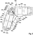
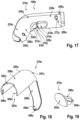
- FIG. 4 to 33 Another exemplary embodiment is shown.
- the exemplary embodiment of Figures 4 to 33 is followed by the letter c.
- the further embodiment of the Figures 4 to 33 differs from the previous exemplary embodiments at least essentially by a design of a drive module 100c and an attachment module 400c.
- Figure 4 shows a drive module 100c.
- the drive module 100c is part of a tool module system 10c.
- the tool module system 10c is designed as a kitchen tool module system 12c.
- the tool module system 10c is designed as a hand tool module system.
- the tool module system 10c is designed as a machine tool system.
- the tool module system 10c is designed as a power tool module system.
- the tool module system 10c is designed as a portable tool module system.
- the tool module system 10c is designed as a hand-held tool module system.
- the tool module system 10c is intended for kitchen use.
- the tool module system 10c is intended for use in a living and/or dining area.
- the tool module system 10c is intended for manual use.
- the tool module system 10c has the drive module 100c.
- the tool module system 10c has at least one attachment module 400c, 480c.
- the at least one attachment module 400c, 480c can be coupled to the drive module 100c.
- the tool module system 10c has a plurality of attachment modules 400c, 480c.
- a first attachment module 400c of the tool module system 10c is in Figure 33 shown.
- the first attachment module 400c is designed as a first tool module 401c.
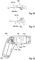
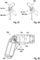
- a second attachment module 480c of the tool module system 10c is in the Figures 20, 21 , 23 and 24 shown.
- the second attachment module 480c is designed as a second tool module 481c.
- the attachment modules 400c, 480c can be designed as mixer attachments, as stirring attachments, as frother attachments, as planing and/or grating attachments, as chopper attachments and/or as mill attachments.
- the drive module 100c is designed as a portable drive module.
- the drive module 100c is designed as a hand-held drive module.
- the drive module 100c has a mass of at most 1000 g, in particular of at most 700 g, advantageously at most 500 g and particularly advantageously at most 350 g.
- the drive module 100c has an in Figure 14 apparent maximum extension 108c of at most 25 cm, in particular at most 22 cm, advantageously at most 20 cm and particularly advantageously at most 19 cm.
- the drive module 100c has a maximum extension 108c of approximately 18.5 cm.
- the drive module 100c can be grasped in a first gripping position.
- the first gripping position is in Figure 20 shown.
- the first gripping position is designed as a pistol grip.
- the drive module 100c can be grasped in a further first gripping position.
- the other first gripping position is in Figure 21 shown.
- the further first gripping position is designed as a reverse pistol grip.
- the drive module 100c can be grasped in a second gripping position.
- the second gripping position is shown in Figure 23.
- the second gripping position is designed as a bar handle, in particular a hand blender handle.
- the drive module 100c can be grasped in a further second gripping position.
- the other second gripping position is in Figure 24 shown.
- the further second gripping position is designed as an inverted bar handle, in particular an inverted hand blender handle.
- the drive module 100c has a drive unit 110c.
- the drive unit 110c is in Figure 4 shown.
- the drive unit 110c is designed as an electrical machine.
- the drive unit 110c is designed as an electric motor.
- the drive unit 110c has a rotor.
- the drive unit 110c has a stator.
- the drive unit 110c is intended for a rotational drive of a drive shaft.
- the drive shaft is rotatably mounted about a rotation axis 124c.
- the drive unit 110c has a plurality of operating functions.
- a first of the operating functions is designed as a counterclockwise rotation function. When the first operating function is activated, the drive unit 110c is intended to move the drive shaft counterclockwise, viewed in the output direction. At least one further first of the operating functions is designed as a clockwise rotation function. When another first operating function is activated, the drive unit 110c is intended to move the drive shaft clockwise, viewed in the output direction.
- a second of the operating functions is designed as an accelerator function.
- the drive unit 110c When the second operating function is activated, the drive unit 110c is intended to move the drive shaft at a speed that can be variably controlled by a user.
- Another second of the operating functions is designed as a soft start function.
- the drive unit 110c When a further second operating function is activated, the drive unit 110c is intended to move the drive shaft at a speed that can be variably controlled by the user.
- the soft start function is activated, the drive unit 110c is intended to keep an angular acceleration of the drive shaft below a positive limit, in particular in the event of a rapid increase in speed specified by the user.
- the drive unit 110c When the soft start function is activated, the drive unit 110c is intended to slowly accelerate the drive shaft up to a speed specified by the user.
- An additional second one of the operating functions is designed as a fixed speed function. When the additional second operating function is activated, the drive unit 110c is intended to move the drive shaft at a constant speed,
- a third of the operating functions is designed as a continuous speed function.
- the drive unit 110c is intended to move the drive shaft at an unmodulated speed.
- Another third of the operating functions is designed as an alternating speed function.
- the drive unit 110c is intended to continuously switch between the left-hand running function and the right-hand running function, in particular by deactivating the pure left-hand running function and the pure right-hand running function.
- An additional third of the operating functions is designed as a pulsating speed function.
- the drive unit 110c is intended to move the drive shaft at a speed that continuously changes between a minimum value, in particular designed as zero, and a maximum value that can be determined by a user.
- Another additional third of the operating functions is designed as a time-dependent speed function.
- Drive unit 110c is intended to move the drive shaft with a predetermined, time-repeated speed curve.
- a fourth of the operating functions is designed as a full torque function.
- the drive unit 110c is intended to move the drive shaft with a maximum torque.
- Another fourth of the operating functions is designed as a partial torque function.
- the drive unit 110c is intended to move the drive shaft with a defined torque value, in particular different from a maximum value.
- the drive unit 110c has at least two operating modes.
- the drive unit 110c has more than two operating modes.
- Each of the operating modes is composed of a combination of several of the operating functions.
- Each of the operating modes is composed of a combination of at least two of the operating functions.
- Availability of the operating modes depends on a design and/or function of an attachment module coupled to the drive module 100c.
- a first of the operating modes is in a coupled state of the drive module 100c and one in Figure 33 shown, designed as a screwdriver module, in particular a screwdriver module, attachment module 400c is available.
- the first operating mode the first operating function and the second operating function are activated.
- Another first of the operating modes is available in the coupled state of the drive module 100c and the attachment module designed as a screwdriver module.
- the further first operating mode the further first operating function and the second operating function are activated.
- a second of the operating modes is available in a coupled state of the drive module 100c and an attachment module, not shown in detail, designed as a chopper module, in particular a herb chopper module.
- the further first operating function and the additional second operating function are activated.
- a further second operating mode is available in the coupled state of the drive module 100c and the attachment module designed as a chopper module.
- the further first operating function and the additional second operating function are activated.
- a speed is higher than in the second operating mode.
- An additional second operating mode is available in the coupled state of the drive module 100c and the attachment module designed as a chopper module. In the additional second operating mode, the additional first operating function and the additional third operating function are activated.
- a third of the operating modes is available in a coupled state of the drive module 100c and an attachment module, not shown in detail, designed as a mill module, in particular a spice mill module.
- the further first operating function and the additional second operating function are activated.
- a fourth of the operating modes is available in a coupled state of the drive module 100c and an attachment module (not shown in detail) designed as a planing and/or grating module, in particular a cheese grater module.
- the first operating function and the additional second operating function are activated.
- a further fourth operating mode is available in the coupled state of the drive module 100c and the attachment module designed as a planing and/or grating module. In the further fourth operating mode, the further first operating function and the additional second operating function are activated.
- a fifth of the operating modes is in a coupled state of the drive module 100c and one in the Figures 20, 21 , 23 and 24 shown, designed as a frother module, in particular a milk frother module, top module 480c is available.
- the further first operating function, the further second operating function and the additional second operating function are activated.
- a further fifth operating mode is available in the coupled state of the drive module 100c and the attachment module designed as a frother module.
- the further first operating function, the further second operating function and the additional second operating function are activated.
- a speed is higher than in the fifth operating mode.
- a sixth of the operating modes is available in a coupled state of the drive module 100c and an attachment module, not shown in detail, designed as a press module, in particular a citrus press module.
- the further first operating function and the additional second operating function are activated.
- the drive unit 110c could have the operating modes listed in the first table below, depending on coupled add-on modules.
- the operating functions listed in the first table are always combined with the second operating function.
- a second line of the first table should be understood as "A seventh operating mode, in particular a screwing-in operating mode, the operating modes are available in a coupled state of the drive module 100c and an attachment module designed as a screwdriver module.
- the further first operating function and the second operating function activated.
- the sixteenth operating mode, the seventeenth operating mode and the eighteenth operating mode are designed as successive operating modes.
- the operating functions of the drive unit 110c are deactivated.
- the drive unit 110c stands still.
- the drive unit 110c is intended to reset a pressing element, in particular a press cone, of an attachment module designed as a press attachment, in particular a lemon press attachment.
- the drive unit 110c could have the operating modes listed in the second table below, depending on coupled add-on modules.
- the operating functions listed in the second table are always combined with the additional second operating function.
- a second line of the second table should be understood as "A nineteenth operating mode, in particular a slow screwing-in operating mode, the operating modes are available in a coupled state of the drive module 100c and an attachment module designed as a screwdriver module.
- the nineteenth operating mode the further first operating function and the additional second operating function is activated.”
- the drive unit 110c has a higher speed than in a corresponding operating state with the suffix "slow”.
- the thirty-seventh operating mode and/or the thirty-eighth operating mode, the thirty-ninth operating mode and the fortieth operating mode and/or the forty-first operating mode are designed as successive operating modes.
- the thirty-ninth operating mode the operating functions of the drive unit 110c are disabled.
- the drive unit 110c stands still.
- the drive unit 110c is intended to reset a pressing element, in particular a press cone, of an attachment module designed as a press attachment, in particular a lemon press attachment.
- the drive unit 110c is intended to to reset a pressing element, in particular a press cone, of an attachment module designed as a press attachment, in particular a lemon press attachment.
- the drive module 100c has an in Figure 4 Gear unit 112c shown.
- the gear unit 112c is arranged coaxially with the drive unit 110c.
- the gear unit 112c is arranged coaxially with the drive shaft.
- the gear unit 112c is arranged coaxially with the rotation axis 124c.
- the transmission unit 112c is connected downstream of the drive unit 110c in the torque flow.
- the transmission unit 112c has a gear transmission.
- the gear transmission is designed as a gear transmission.
- the gear transmission is designed as a spur gear.
- the gear train is designed as a planetary gear train.
- the gear unit 112c has a plurality of gear elements 116c, only a part of which is provided with reference numbers for the sake of clarity.
- the gear elements 116c include shafts and wheels, in particular gears and preferably spur gears.
- the gear unit 112c has a gear housing 114c.
- the gear housing 114c encloses the gear elements 116c.
- a gear unit can be designed as a crank gear, as a cam gear, as a roller gear and/or as a locking gear.
- the gear unit 112c is intended to change the speed.
- the gear unit 112c is intended to change the torque.
- the gear unit 112c is intended to translate a speed of the drive shaft to a speed of a main output shaft 118c.
- the transmission unit 112c is intended to transmit torque from the drive shaft to the main output shaft 118c.
- a gear unit can be provided to change a rotation axis and/or a gear gear can be designed as a bevel gear.
- the drive module 100c has the main output shaft 118c.
- the main output shaft 118c is arranged coaxially with the drive unit 110c.
- the main output shaft 118c is arranged coaxially with the input shaft.
- the main output shaft 118c is arranged coaxially with the transmission unit 112c.
- the main output shaft 118c is rotatably mounted about the rotation axis 120c.
- the main output shaft 118c is connected downstream of the drive unit 110c in the torque flow.
- the main output shaft 118c is connected downstream of the transmission unit 112c in the torque flow.
- the main output shaft 118c has a recess 120c.
- An output-side end of the main output shaft 118c has the recess 120c.
- the recess 120c is designed as a hexagonal recess.
- the recess 120c has a hexagonal cross section.
- the recess 120c is intended to accommodate a shaft.
- the drive module 100c has a main board 204c.
- the main board 204c is in the Figures 4 to 10 shown.
- the main board 204c has an in Figure 7 visible main extension plane 206c, which forms an angle of at most 60 ° with a main extension plane 102c of the drive module 100c.
- the main extension plane 206c of the main board 204c and the main extension plane 102c of the drive module 100c are arranged parallel to one another.
- the main extension plane 206c of the main board 204c and the main extension plane 102c of the drive module 100c are arranged at a distance from one another.
- the main extension plane 206c of the main board 204c and the main extension plane 102c of the drive module 100c are at a distance of at least 5 mm.
- the main extension plane 206c of the main board 204c and the main extension plane 102c of the drive module 100c are at a maximum distance of 15 mm.
- the main board 204c has two sections 208c, 210c.
- the sections 208c, 210c are formed in one piece.
- the main board 204c has a first section 208c.
- the first section 208c essentially has the shape of a rectangle when viewed perpendicular to the main extension plane 206c of the main board 204c.
- the main board 204c has a second section 210c.
- the second section 210c viewed perpendicular to the main extension plane 206c of the main board 204c, essentially has the shape of a triangle, in particular a right-angled triangle.
- the second section 210c borders with a hypotenuse on a short side edge of the first section 208c.
- a particularly geometric center of gravity of the second section 210c is arranged closer to the drive unit 110c than a particularly geometric center of gravity of the first section 208c.
- the motherboard 204c includes three interfaces 212c, 214c, 216c.
- the interfaces 212c, 214c, 216c each have an interface opening.
- the interfaces 212c, 214c, 216c each have a conductor contact.
- the interfaces 212c, 214c, 216c are designed as cable lugs.
- a first interface 212c of the interfaces 212c, 214c, 216c is arranged on a side of the first subsection 208c facing the second subsection 210c.
- a second interface 214c of the interfaces 212c, 214c, 216c is arranged on a side of the first subsection 208c facing the second subsection 210c.
- a third interface 216c of the interfaces 212c, 214c, 216c is arranged on a side of the first subsection 208c facing away from the second subsection 210c.
- a motherboard could have one of three different numbers of interfaces.
- the main board 204c can have at least part of an electronics unit 168c, a reception and/or communication unit 176c and/or a storage unit 178c.
- the main board 204c includes a plurality of electronic components and/or assemblies, for example conductor tracks, capacitors, circuits, memory components and/or computing components, in particular microchips.
- the electronic components and/or assemblies have at least one signal transmission, energy storage, data storage, control, regulation and/or calculation function.
- the drive module 100c has an energy storage unit 180c.
- the energy storage unit 180c is in the Figures 4 to 10 shown.
- the energy storage unit 180c is designed as an electrical energy storage unit.
- the energy storage unit 180c is designed as a rechargeable energy storage unit.
- the energy storage unit 180c is designed as a battery unit, in particular a lithium-ion battery unit.
- the energy storage unit 180c is intended to supply at least the drive unit 110c with energy, in particular electrical energy.
- the energy storage unit 180c has a plurality of energy storage cells 182c, 184c.
- the energy storage unit 180c includes two energy storage cells 182c, 184c.
- the energy storage unit 180c has exactly two energy storage cells 182c, 184c.
- an energy storage unit could also have more than two energy storage cells.
- the energy storage unit 180c includes a first energy storage cell 182c with a first center of gravity 194c, in particular a first center of mass.
- the first energy storage cell 182c essentially has a shape of a cylinder.
- the first energy storage cell 182c is designed as an electrical energy storage cell.
- the first energy storage cell 182c is designed as a rechargeable energy storage cell.
- the first energy storage cell 182c is designed as a battery cell, in particular a lithium-ion battery cell.
- the energy storage unit 180c includes a second energy storage cell 184c with a second center of gravity 196c, in particular a second center of mass.
- the second energy storage cell 184c is designed as an electrical energy storage cell.
- the second energy storage cell 184c is designed as a rechargeable energy storage cell.
- the second energy storage cell 184c is designed as a battery cell, in particular a lithium-ion battery cell.
- the second energy storage cell 184c essentially has a shape of a cylinder.
- a longitudinal extension axis 192c of the second energy storage cell 184c is arranged parallel to a longitudinal extension axis 190c of the first energy storage cell 182c.
- the energy storage cells 182c, 184c include three plug contacts 198c, 200c, 202c, which are in Figure 10 are shown.
- the three plug contacts 198c, 200c, 202c correspond to the interfaces 212c, 214c, 216c.
- the first energy storage cell 182c includes a first plug contact 198c of the plug contacts 198c, 200c, 202c.
- the first plug contact 198c corresponds to the first interface 212c.
- the first plug contact 198c and the first interface 212c are provided to form a first plug connection.
- the second energy storage cell 184c includes a second plug contact 200c of the plug contacts 198c, 200c, 202c.
- the second plug contact 200c corresponds to the second interface 214c.
- the second plug contact 200c and the second interface 214c are provided to form a second plug connection.
- the first energy storage cell 182c and the second energy storage cell 184c include a common third plug contact 202c of the plug contacts 198c, 200c, 202c.
- the third plug contact 202c is arranged at an end of the first energy storage cell 182c opposite the first plug contact 198c.
- the third plug contact 202c is arranged at an end of the second energy storage cell 182c opposite the second plug contact 200c.
- the third plug contact 202c corresponds to the third interface 216c.
- the third plug contact 202c and the third interface 216c are provided to form a third plug connection.
- FIG. 5 , 6 and 7 is a center of gravity axis 195c through the first center of gravity 194c of the first energy storage cell 182c and through the second center of gravity 196c of the second energy storage cell 184c.
- the center of gravity axis 195c forms an angle of at most 60° with a main extension plane 102c of the drive module 100c.
- the center of gravity axis 195c is arranged parallel to the main extension plane 102c of the drive module 100c.
- the center of gravity axis 195c is arranged at a distance from the main extension plane 102c of the drive module 100c.
- the center of gravity axis 195c is at a distance of more than 1 mm from the main extension plane 102c of the drive module 100c.
- the center of gravity axis 195c is at a distance of less than 3 mm from the main extension plane 102c of the drive module 100c.
- the center of gravity axis 195c is at a distance of approximately 2 mm from the main extension plane 102c of the drive module 100c.
- a maximum number of energy storage cells 182c, 184c of the energy storage unit 180c arranged one behind the other perpendicular to the main extension plane 102c of the drive module 100c is one.
- the first energy storage cell 182c and the second energy storage cell 184c are arranged without overlap when viewed perpendicular to the main extension plane 102c of the drive module 100c.
- the first energy storage cell 182c and the second energy storage cell 184c can be plugged onto the main board 204c independently of one another.
- a maximum number of energy storage cells 182c, 184c of the energy storage unit 180c arranged one behind the other in the main extension plane 102c is two.
- the first energy storage cell 182c and the second energy storage cell 182c are arranged one behind the other in the main extension plane 102c.
- the maximum number of energy storage cells arranged one behind the other perpendicular to the main extension plane 102c of the drive module 100c 182c, 184c is less than the maximum number of energy storage cells 182c, 184c arranged one behind the other in the main extension plane 102c.
- the drive module 100c has a housing unit 218c.
- the housing unit 218c is in the Figures 11 to 19 shown in more detail.
- the housing unit 218c is pistol-shaped.
- the housing unit 218c is designed in several parts.
- the housing unit 218c consists at least partially of a plastic, in particular a thermoplastic and preferably of acrylonitrile-butadiene-styrene copolymers (ABS).
- ABS acrylonitrile-butadiene-styrene copolymers
- the housing unit 218c consists at least largely of a plastic, in particular of a thermoplastic and preferably of ABS.
- the housing unit 218c has an in. parallel to the axis of rotation 124c Figure 14 shown maximum extension 228c of at most 18 cm.
- the housing unit 218c has a maximum extension 228c of approximately 15.3 cm parallel to the axis of rotation 124c.
- the housing unit 218c has a maximum extension 230c of at most 15 cm perpendicular to the axis of rotation 124c.
- the housing unit 218c has a maximum extension 230c of approximately 12.1 cm perpendicular to the axis of rotation 124c.
- the housing unit 218c includes a drive housing section 220c.
- the drive housing portion 220c essentially has a shape of a hollow cylinder.
- a cross section through the drive housing section 220c perpendicular to a longitudinal extension axis 222c of the drive housing section 220c essentially has the shape of a circular ring.
- a longitudinal extent of the drive housing section 220c is larger than a mean diameter of the drive housing section 220c.
- a longitudinal extent of the drive housing section 220c is less than twice the diameter of the drive housing section 220c.
- extension 106c of the drive housing section 220c perpendicular to the main extension plane 102c of the drive module 100c is at most 55 mm.
- the extension 106c of the drive housing section 220c perpendicular to the main extension plane 102c of the drive module 100c is approximately 55 mm.
- the drive housing section 220c encloses the in Figure 4 shown drive unit 110c.
- a longitudinal extension axis 222c of the drive housing section 220c is arranged substantially parallel to the rotation axis 124c.
- a cavity 221c is arranged between the drive housing section 220c and the drive unit 110c.
- the drive housing section 220c encloses the in Figure 4 shown gear unit 112c.
- the drive housing section 220c is arranged substantially coaxially with the gear unit 112c.
- the housing unit 218c includes a handle housing portion 224c.
- the handle housing section 224c tapers continuously along a longitudinal extension axis 226c of the handle housing section 224c towards a free end 225c of the handle housing section 224c.
- the handle housing section 224c tapers continuously towards the free end 225c when viewed in the center of gravity axis 195c.
- a cross section through the handle housing portion 224c perpendicular to the longitudinal extension axis 226c of the handle housing portion 224c has a substantially oval ring shape.
- the handle housing section 224c has an in. perpendicular to the main extension plane 102c of the drive module 100c Figure 12 shown maximum extension 104c of at most 44 mm.
- the handle housing section 224c has an extension 104c of approximately 35 mm perpendicular to the main extension plane 102c of the drive module 100c.
- the handle housing section 224c has an in. parallel to the center of gravity axis 195c Figure 14 shown maximum extension 232c of at most 60 mm.
- the handle housing section 224c has a maximum extension 232c of approximately 45 mm parallel to the center of gravity axis 195c.
- the maximum extension 104c of the handle housing section 224c perpendicular to the main extension plane 102c of the drive module 100c is less than the maximum extension 232c of the handle housing section 224c parallel to the center of gravity axis 195c.
- the handle housing section 224c encloses the in Figure 4 shown main board 204c to a large extent.
- the handle housing section 224c largely encloses the energy storage unit 180c.
- An inner narrow side 229c of the handle housing section 224c is separated from the second energy storage cell 184c by a cavity 231c.
- the longitudinal extension axis 226c of the handle housing section 224c is arranged at least substantially parallel to the longitudinal extension axis 190c of the first energy storage cell 182c.
- the longitudinal extension axis 226c of the handle housing section 224c is arranged substantially parallel to the longitudinal extension axis 192c of the second energy storage cell 184c.
- the longitudinal extension axis 226c of the handle housing section 224c is arranged at least substantially perpendicular to the center of gravity axis 195c.
- the handle housing section 224c is arranged at an angle to the drive housing section 220c.
- An in Figure 14 The interior angle 234c shown between the longitudinal extension axis 222c of the drive housing section 220c and the longitudinal extension axis 226c of the handle housing section 224c is at least 80°.
- the interior angle 234c is at most 170°.
- the interior angle 234c is approximately 110°.
- the drive housing section 220c and the handle housing section 224c span the main extension plane 102c of the drive module 100c.
- a curved transition region 236c is arranged between the handle housing section 224c and the drive housing section 220c.
- the handle housing section 224c and the drive housing section 220c are connected via the transition region 236c.
- One longitudinal end of the handle housing section 224c and the drive housing section 220c borders the transition region 236c.
- the drive housing section 220c and the transition region 236c are partially formed in one piece.
- the handle housing section 224c and the transition region 236c are partially formed in one piece.
- the drive housing section 220c, the transition region 236c and the handle housing section 224c are partially formed in one piece.
- the transition region 236c includes a convexly curved outer area 238c.
- the transition region 236c includes a saddle-shaped curved inner region 240c.
- the housing unit 218c has a base housing 242c.
- the base housing 242c extends over the drive housing portion 220c.
- the base housing 242c extends over the handle housing portion 224c.
- the base case 242c extends over the transition area 236c.
- the base housing 242c consists at least largely of a plastic, in particular a thermoplastic.
- the base housing 242c consists entirely of a plastic, in particular a thermoplastic.
- the base housing 242c is intended to fix functional elements, in particular all functional elements of the drive module 100c.
- the base housing 242c is intended to fix the main board 204c.
- the base housing 242 is intended to fix the drive unit 110c.
- the base housing 242c is intended to fix the gear unit 112c.
- the base housing 242c has a viewing area 248c, 250c.
- the viewing area 248c, 250c is visible in a mounted state of the drive module 100c.
- the viewing area 248c, 250c extends over the drive housing section 220c, in particular in the mounted state of the drive module 100c on an underside of the drive housing section 220c, preferably with respect to the first gripping position.
- the viewing area 248c, 250c extends over the handle housing section 224c, in particular in the mounted state of the drive module 100c on a front side of the handle housing section 224c, which is preferably facing away from a user in the first gripping position.
- the viewing area 248c, 250c extends over the transition area 236c, in particular the interior area 240c of the transition area 236c.
- the base housing 242c has a support area 252c, 254c.
- the carrier area 252c, 254c is covered in the mounted state of the drive module 100c.
- the carrier region 252c, 254c extends over the drive housing section 220c, in particular in the mounted state of the drive module 100c on an upper side of the drive housing section 220c, preferably with respect to the first gripping position.
- the carrier region 252c, 254c extends over the handle housing section 224c, in particular in the mounted state of the drive module 100c on a rear side of the handle housing section 224c, preferably facing a user in the first gripping position.
- the carrier region 252c, 254c extends over the transition region 236c, in particular the outer area 238c of the transition region 236c.
- the base housing 242c has a housing stage 256c, 258c.
- the viewing area 248c, 250c and the carrier area 252c, 254c are separated from each other by the housing step 256c, 258c.
- the viewing area 248c, 250c rises on the housing step 256c, 258c relative to the carrier area 252c, 254c.
- the base housing 242c is designed in several parts.
- the base housing 242c is designed in two parts.
- the base housing 242c includes a first base housing component 244c.
- the first base housing component 244c consists at least largely of a plastic, in particular a thermoplastic.
- the first base housing component 244c consists of a plastic, in particular a thermoplastic.
- the first base housing component 244c is designed as a first half-shell. In the assembled state of the drive module 100c, the first base housing component 244c is approximately limited by the main extension plane 102c of the drive module 100c.
- the first base housing component 244c has a plurality of first positive and/or frictional locking elements 276c.
- the first positive and/or frictional elements 276c are in Figure 29 shown.
- the first positive and/or frictional engagement elements 276c are arranged on a housing edge between a concave housing inside and a convex housing outside of the first base housing component 244c.
- the first base housing component 244c has a first viewing area 248c.
- the first base housing component 244c has a first support region 252c.
- the first viewing area 248c and the first carrier area 252c are separated from one another by a first housing stage 256c.
- the first viewing area 248c rises on the first housing stage 256c relative to the first support area 252c.
- the first base housing component 244c has a plurality of receiving elements 260c, 262c, 264c, 266c.
- the first base housing component 244c has four receiving elements 260c, 262c, 264c, 266c.
- a first receiving element 260c of the receiving elements 260c, 262c, 264c, 266c is part of a last third of the handle housing section 224c comprising the end 225c.
- the first receiving element 260c is part of the first viewing area 248c.
- a second receiving element 262c of the receiving elements 260c, 262c, 264c, 266c is part of the Outer area 238c of the transition area 236c.
- the second receiving element 262c is part of the first support area 252c.
- a third receiving element 264c of the receiving elements 260c, 262c, 264c, 266c is part of a half of the drive housing section 220c facing away from the transition region 236c.
- the third receiving element 266c is part of the first viewing area 248c.
- a fourth receiving element 266c of the receiving elements 260c, 262c, 264c, 266c is part of the half of the drive housing section 220c facing away from the transition region 236c.
- the fourth receiving element 266c is part of the first support area 252c.
- the receiving elements 260c, 262c, 264c, 266c are essentially designed to have the same shape and function.
- the first receiving element 260c is described in more detail below as an example.
- the features of the first receiving element 260c apply analogously to the second receiving element 262c, to the third receiving element 264c and to the fourth receiving element 266c.
- the first receiving element 260c is designed as a first screw dome.
- the first receiving element 260c is embedded in a housing shell of the first base housing component 244c.
- the first receiving element 260c is intended to receive a first connecting element, in particular a bolt and/or a screw.
- the first receiving element 260c encloses a first recess, which essentially has the shape of a circular cylinder.
- the first recess is accessible from an inside of the housing of the first base housing component 244c, in particular in an unassembled state of the first base housing component 244c.
- the base housing 242c includes a second base housing component 246c.
- the second base housing component 246c consists at least largely of a plastic, in particular a thermoplastic.
- the second base housing component 246c consists of a plastic, in particular a thermoplastic.
- the second base housing component 246c is designed as a second half-shell. In the assembled state of the drive module 100c, the second base housing component 246c is approximately limited by the main extension plane 102c of the drive module 100c.
- the first base housing component 244c and the second base housing component 246c are designed to be essentially mirror-symmetrical to one another.
- the second base housing component 246c has a plurality of second positive and/or frictional locking elements, not shown in detail.
- the second positive and/or frictional engagement elements are arranged on a housing edge between a concave housing inside and a convex housing outside of the second base housing component 246c.
- the second positive and/or frictional elements correspond to the first positive and/or frictional elements 276c.
- the first positive and/or frictional engagement elements 276c and the second positive and/or frictional engagement elements are provided for a frictional and/or positive connection of the first base housing component 244c and the second base housing component 246c.
- the second base housing component 246c has a second viewing area 250c.
- the second base housing component 246c has a second support region 254c.
- the second viewing area 250c and the second carrier area 254c are separated from one another by a second housing stage 258c.
- the second viewing area 250c rises on the second housing stage 258c relative to the second support area 254c.
- the second base housing component 246c has a plurality of further receiving elements 268c, 270c, 272c, 274c.
- the second base housing component 246c has four further receiving elements 268c, 270c, 272c, 274c.
- a first further receiving element 268c of the further receiving elements 268c, 270c, 272c, 274c is part of the last third of the handle housing section 224c comprising the end 225c.
- the first further receiving element 268c is part of the second viewing area 250c.
- a second further receiving element 270c of the further receiving elements 268c, 270c, 272c, 274c is part of the outer region 238c of the transition region 236c.
- the second further receiving element 270c is part of the second support area 254c.
- a third further receiving element 272c of the receiving elements 268c, 270c, 272c, 274c is part of a half of the drive housing section 220c facing away from the transition region 236c.
- the third additional receiving element 272c is part of the second viewing area 250c.
- a fourth further receiving element 274c of the receiving elements 268c, 270c, 272c, 274c is part of the half of the drive housing section 220c facing away from the transition region 236c.
- the fourth further receiving element 274c is part of the second support area 254c.
- the further receiving elements 268c, 270c, 272c, 274c are essentially designed to have the same shape and function.
- the first further receiving element 268c is described in more detail below as an example.
- the features of the first further receiving element 268c apply analogously to the second further receiving element 270c, to the third further receiving element 272c and to the fourth further receiving element 274c.
- the first further receiving element 268c is designed as a first further screw dome.
- the first further receiving element 268c is embedded in a housing shell of the second base housing component 246c.
- the first further receiving element 268c is intended to receive the first connecting element, in particular a first screw element.
- the first further receiving element 268c corresponds to the first receiving element 260c.
- the first further receiving element 268c encloses a first further recess, which essentially has a circular cylindrical shape.
- the first further recess is accessible from an inside of the housing of the second base housing component 246c, in particular in the unassembled state of the second base housing component 246c.
- the first further recess is accessible from an outside of the housing of the second base housing component 246c, in particular in the unassembled state of the second base housing component 246c.
- the first connecting element can be inserted through the first further recess of the first further receiving element 268c into the first recess of the first receiving element 260c.
- the first viewing area 248c and the second viewing area 250c form the viewing area 248c, 250c of the base housing 242c in a connected state of the first base housing component 244c and the second base housing component 246c.
- the first carrier region 252c and the second carrier region 254c form the carrier region 252c, 254c of the base housing 242c in a connected state of the first base housing component 244c and the second base housing component 246c.
- the first housing stage 256c and the second housing stage 258c form the housing stage 256c, 258c of the base housing 242c in a connected state of the first base housing component 244c and the second base housing component 246c.
- the base housing 242c has a first cover unit 278c.
- the first panel unit 278c is in the Figures 11 and 19 shown.
- the first cladding unit 278c is designed in one piece, in particular in one piece.
- the first cladding unit 278c is designed as a first plug.
- the first cladding unit 278c is intended to clad and/or cover the third further receiving element 272c.
- the first cladding unit 278c is intended to protect the third additional receiving element 272c from contamination.
- the first cladding unit 278c includes a first base body 280c.
- the first cladding unit 278c includes a first cover element 282c.
- the first cover element 282c has a first curved viewing surface. The curvature of the first viewing surface is adapted to a curvature of the second base housing component 246c in a surrounding area of the first further receiving element 268c.
- the first cladding unit 278c includes a first guide element 284c.
- the first guide element 284c is designed as a guide rib.
- the first guide element 284c is designed as a mounting rib.
- the first guide element 284c is intended to guide the first cladding unit 278c in a corresponding housing recess during assembly on the first further receiving element 268c.
- the base housing 242c has a second cover unit 286c.
- the second trim unit 286c is in Figure 11 shown.
- the second cladding unit 286c essentially corresponds to the first cladding unit 278c.
- the second cladding unit 286c is intended to clad and/or cover the first further receiving element 268c.
- the second cladding unit 286c is intended to protect the first further receiving element 268c from contamination.
- the second cladding unit 286c has dimensions that differ from the first cladding unit 278c.
- a second curved viewing surface of a second cover element of the second cladding unit is adapted to a curvature of the second base housing component 246c in a surrounding area of the third further receiving element 272c.
- the base housing 242c has a plurality of recesses 288c, 290c, 292c.
- the recesses 288c, 290c, 292c are in Figure 17 shown.
- the base housing 242c has three recesses 288c, 290c, 292c.
- the recesses 288c, 290c, 292c are embedded in the carrier area 252c, 254c of the base housing 242c.
- a first recess 288c of the recesses 288c, 290c, 292c is embedded in the first base housing component 244c.
- the first recess 288c is arranged in a last quarter of the drive housing section 220c facing away from the transition region 236c.
- a second recess 290c of the recesses 288c, 290c, 292c is embedded in the second base housing component 246c.
- the second recess 290c is arranged in the last quarter of the drive housing section 220c facing away from the transition region 236c.
- a third recess 292c of the recesses 288c, 290c, 292c is half embedded in the first base housing component 244c and half in the second base housing component 246c.
- the third recess 292c is arranged at the end 225c of the handle housing section 224c.
- the drive module 100c has two visible components 294c, 350c.
- the two visible components 294c, 350c are designed as metallic-coated visible components.
- the two visible components 294c, 350c are designed as metal-coated visible components.
- the two visible components 294c, 350c are designed as galvano-coated visible components.
- the drive module 100c has a first visible component 294c.
- the first visible component is in Figure 18 shown.
- the first visible component 294c is designed as a metallic-coated visible component.
- the first visible component 294c is designed as a metal-coated visible component.
- the first visible component 294c is designed as a galvano-coated visible component.
- the housing unit 218c has a first visible component 294c.
- the first visible component 294c is designed as a housing attachment. In an assembled state, the first visible component 294c covers the carrier area 252c, 254c of the base housing 242c.
- the first visible component 294c and the visible area 248c, 250c of the base housing 242c form a large part of a visible surface of the drive module 100c.
- a visible surface of the first visible component 294c corresponds at least 30% of the visible area of the drive module 100c.
- the visible area of the first visible component 294c corresponds to a maximum of 90% of the visible area of the drive module 100c.
- the first visible component 294c covers at least one housing connection in an assembled state.
- the first visible component 294c covers the second further receiving element 270c. In the assembled state, the first visible component 294c covers the fourth further receiving element 274c.
- the first visible component 294c is intended to protect the second further receiving element 270c from contamination.
- the first visible component 294c is intended to protect the fourth further receiving element 274c from contamination.
- the first visible component 294c has a base body.
- the base body of the first visible component 294c consists of a plastic, in particular a thermoplastic and preferably ABS.
- the first visible component 294c has at least one metallic coating, in particular metal coating.
- the first visible component 294c has a plurality of metal coatings, in particular galvanic coatings.
- the first visible component 294c has a matt surface.
- the first visible component 294c has, for example, a rose gold surface.
- a visible component could have a shiny and/or a further roughened, for example brushed, surface structure and/or a surface in silver, in dark gray-silver, in copper and/or in other metallic colors. This can create an advantageous visual impression.
- the first visible component 294c has several sections in terms of a shape.
- the first visible component 294c has a first section 296c.
- the first section 296c has a horseshoe-shaped cross section.
- the first section 296c forms part of the drive housing section 220c, in particular in the assembled state of the first visible component 294c.
- An end of the first visible component 294c facing away from the transition region 236c in the assembled state of the first visible component 294c has a recess 302c.
- the first visible component 294c has a second section 298c.
- the second section 298c is arranged at an angle to the first section 296c.
- a longitudinal extension axis of the first section 296c and a longitudinal extension axis of the second section 298c form an angle of at least 80°.
- the longitudinal axis of extension of the first section 296c and the longitudinal axis of extension of the second section 298c enclose an angle of at most 170°.
- the longitudinal axis of the first section 296c and the longitudinal axis of the second section 298c form an angle of approximately 107°.
- the second section 298c forms part of the handle housing section 224c, in particular in the assembled state of the first visible component 294c.
- the first visible component 294c has a transition section 297c between the first section 296c and the second section 298c.
- the transition section 297c forms part of the transition region 236c of the housing unit 218c.
- the transition section 297c forms part of the outer region 238c of the transition region 236c.
- the transition section 297c has a first opening.
- the transition section 297c has a second opening.
- the first visible component 294c has a nose 300c.
- the nose 300c adjoins one end of the second section 298c.
- the nose 300c closes off the first visible component 294c.
- the nose 300c is curved.
- a tip of the nose 300c forms the end 225c of the handle housing section 224c in the assembled state of the first visible component 294c.
- the first visible component 294c is designed as a clip component.
- the first visible component 294c is designed as a final clip component.
- the first visible component 294c is intended for a clip connection to the base housing 242c.
- the first visible component 294c has a fixing unit 303c.
- the fixing unit 303c is intended to fix the first visible component 294c on the base housing 242c.
- the fixing unit 303c includes a first fixing element 304c.
- the first fixing element 304c is designed as a latching element, in particular latching hook.
- the first fixing element 304c is arranged on the first section 296c.
- the first fixing element 304c is intended to fit into the first recess 288c grab, especially snap into place.
- the fixing unit 303c includes a second fixing element 306c.
- the second fixing element 306c is designed as a latching element, in particular latching hook.
- the second fixing element 306c is arranged on the first section 296c.
- the second fixing element 306c is intended to engage, in particular to snap into, the second recess 290c.
- the fixing unit 303c includes a third fixing element 308c.
- the third fixing element 308c is designed as a latching element, in particular latching hook.
- the third fixing element 308c is arranged on the nose 300c.
- the third fixing element 308c is intended to engage, in particular to snap into, the third recess 292c.
- the drive module 100c has two actuation units 310c, 348c.
- the drive module 100c has a first actuation unit 310c.
- the first actuation unit 310c is, for example, in the Figures 5 and 17 shown.
- the first actuation unit 310c is designed as a pressure actuation unit.
- the first actuation unit 310c is intended for manual adjustment of at least one drive parameter of the drive unit 110c.
- the drive parameter is at least designed as a speed. Alternatively or additionally, a drive parameter could be designed as a torque, as an operating function and/or as an operating mode.
- the first actuation unit 310c is partially arranged in the curved transition region 236c between the handle housing section 224c and the drive housing section 220c.
- the first actuation unit 310c is arranged in the interior region 240c of the transition region 236c.
- the first actuation unit 310c is partially arranged in the drive housing section 220c.
- the first actuation unit 310c is partially arranged on the underside of the drive housing section 220c.
- the first actuation unit 310c is partially arranged in the handle housing section 224c.
- the first actuation unit 310c is partially arranged on the front of the handle housing section 224c.
- the first actuation unit 310c has two actuation surfaces 312c, 314c.
- the first actuation unit 310c has a first actuation surface 312c.
- the first actuation surface 312c faces in at least one direction a concave shape.
- the first actuation surface 312c has a concave shape when viewed perpendicular to the main extension plane 102c of the drive module 100c.
- the first actuation surface 310c is saddle-shaped.
- the first actuation unit 310c has a second actuation surface 314c.
- the second actuation surface 314c is at least substantially parallel to a longitudinal extension axis 222c of the drive housing section 220c.
- the actuation surfaces 312c, 314c are intended for fundamentally different handling operations.
- the first actuation surface 312c is intended for the first gripping position.
- the first actuation surface 312c is intended for the further first gripping position.
- the first actuation surface 312c is arranged in the first gripping position within index finger reach.
- the first actuation surface 312c is arranged in the further first gripping position within little finger reach.
- the first actuation surface 312c has a longitudinal extent of at least 2 cm.
- the first actuation surface 312c has a transverse extent of at least 1 cm.
- the second actuation surface 314c is intended for the second gripping position.
- the second actuation surface 314c is arranged in the second gripping position within thumb reach.
- the second actuation surface 314c is intended for the further second gripping position.
- the second actuation surface 314c is arranged in the further second gripping position within reach of the index finger.
- the second actuation surface 314c has a longitudinal extent of at least 2 cm.
- the second actuation surface 314c has a transverse extension of at least 1 cm.
- the first actuation unit 310c has a first actuation element 316c.
- the first actuating element 316c is partially arranged in the handle housing section 224c, in particular at one end of the handle housing section 224c.
- the first actuating element 316c is partially arranged in the transition region 236c.
- the first actuating element 316c is embedded in the housing unit 218c.
- the first actuating element 316c is embedded in the base housing 242c.
- the first actuating element 316c is embedded between the first base housing component 244c and the second base housing component 246c.
- the first actuating element 316c is arranged in at least one gripping position within index finger reach.
- the first actuator 316c is the The first gripping position is within reach of the index finger.
- Figure 22 shows the first actuation element 316c in an actuated state.
- the first actuating element 316c is tongue-shaped.
- the first actuation element 316c has the first actuation surface 312c.
- the first actuation surface 312c rises above the housing unit 218c by at least 2 mm.
- the first actuation surface 312c rises from the housing unit 218c by approximately 4 mm.
- the first actuating element 316c is designed as a switch, in particular a pressure switch and/or an accelerator switch. An increasing actuation pressure on the first actuation element 316c causes an increasing speed of the drive unit 110c.
- the first actuation unit 310c has a further first actuation element 318c.
- the further first actuating element 318c is arranged in the drive housing section 220c.
- the further first actuating element 318c is embedded in the housing unit 218c.
- the further first actuating element 318c is embedded in the base housing 242c.
- the further first actuating element 318c is embedded between the first base housing component 244c and the second base housing component 246c.
- the further first actuating element 318c is arranged in at least one gripping position within index finger reach.
- the further first actuating element 318c is arranged in the further second gripping position within reach of the index finger.
- Figure 25 shows the further first actuating element 318c in an actuated state.
- the further first actuating element 318c is tongue-shaped.
- the further first actuation element 318c has the second actuation surface 314c.
- the second actuation surface 314c rises above the housing unit 218c by at least 2 mm.
- the second actuation surface 314c rises from the housing unit 218c by approximately 4 mm.
- a dome-shaped longitudinal end of the first actuation element 316c and a dome-shaped longitudinal end of the further first actuation element 318c are arranged facing each other.
- a flat longitudinal end of the first actuator 316c and a flat longitudinal end of the further first actuating element 318c are arranged facing away from each other.
- the further first actuating element 318c is designed as a switch, in particular a pressure switch and/or an accelerator switch. An increasing actuation pressure on the further first actuation element 318c causes an increasing speed of the drive unit 110c.
- the further first actuation element 318c is redundant to the first actuation element 316c.
- the further first actuating element 318c is functionally redundant to the first actuating element 316c.
- the drive module 100c has a separating element 320c.
- the curved transition region 236c has the separating element 320c.
- the separating element 320c is designed as an elevation of the curved transition region 236c.
- the separating element 320c is designed as a separating rib.
- the separating element 320c is arranged between the first actuating element 316c and the further first actuating element 318c.
- the separating element 320c separates the first actuating element 316c and the further first actuating element 318c from one another.
- Figure 26 shows the first actuation element 316c and the further first actuation element 318c in an actuated state.
- the separating element 320c rises above the first actuation element 316c and above the further first actuation element 318c.
- the separating element 320c makes it more difficult to actuate the first actuation element 316c and/or the further first actuation element 318c.
- the drive module 100c has a switching element 326c.
- the switching element 326c is, for example, in Figure 5 shown.
- the switching element 326c is pin-shaped.
- the switching element 326c is designed as a, in particular spring-loaded, plunger.
- the switching element 326c is mounted movably along a longitudinal axis of the switching element 326c.
- the switching element 326c is Can be equally actuated via the actuation surfaces 312c, 314c of the first actuation unit 310c.
- the actuation surfaces 312c, 314c are functionally redundant.
- the switching element 326c can be actuated equally via the first actuation element 316c and via the further first actuation element 318c.
- the switching element 326c is coupled to the first actuation element 316c and to the further first actuation element 318c.
- the drive module 100c has a spring element 328c.
- the spring element 328c is designed as a compression spring element.
- the spring element 328c is designed as a coil spring.
- a longitudinal axis of extension of the spring element 328c corresponds to a longitudinal axis of extension of the switching element 326c.
- the spring element 328c partially surrounds the switching element 326c.
- the spring element 328c winds around the switching element 326c.
- the spring element 328c is intended to exert a restoring force on the switching element 326c.
- the drive module 100c has an electrical assembly 344c.
- the assembly 344c is arranged perpendicular to the main extension plane 102c of the drive module 100c at an intersection of the longitudinal extension axis 222c of the drive housing section 220c and the longitudinal extension axis 226c of the handle housing section 224c.
- the assembly 344c is designed as a potentiometer.
- the assembly 344c is intended to influence at least one electrical resistance depending on a mechanical movement of the switching element 326c.
- the assembly 344c is intended to convert a mechanical movement of the switching element 326c into an electrical signal, in particular a control signal.
- the switching element 326c In the in Figure 22 shown actuated state of the first actuating element 316c, the switching element 326c is displaced in the direction of the electrical assembly 344c. In the actuated state of the first actuating element 316c, the switching element 326c acts on the electrical assembly 344c. In the in Figure 25 shown actuated state of the further first actuating element 318c, the switching element 326c is displaced in the direction of the electrical assembly 344c. In the actuated state of the further first actuating element 318c, the switching element 326c acts on the electrical assembly 344c.
- the drive module 100c has a leaf spring element 322c.
- the leaf spring element 322c is designed as a spring plate.
- the leaf spring element 322c is intended to exert a restoring force on the first actuating element 316c.
- the leaf spring element 322c is intended to press the first actuating element 316c out of the housing unit 218c.
- the leaf spring element 322c is intended to fix the first actuating element 316c on the housing unit 218c, in particular on the handle housing section 224c.
- the drive module 100c has a further leaf spring element 323c.
- the further leaf spring element 323c is designed as a further spring plate.
- the further leaf spring element 323c is intended to exert a restoring force on the further first actuating element 318c.
- the further leaf spring element 323c is intended to press the further first actuating element 318c out of the housing unit 218c.
- the further leaf spring element 323c is intended to fix the further first actuating element 318c on the housing unit 218c, in particular on the handle housing section 224c.
- the drive module 100c has a second actuation unit 348c.
- the second actuation unit 348c is, for example, in the Figures 27 and 28 shown.
- the second actuation unit 348c is designed as a pressure actuation unit.
- the second actuation unit 348c is intended for manual actuation of the drive unit 110c.
- the second actuation unit 348c has a second actuation element 352c.
- the second actuation element 352c is arranged in the curved transition region 236c.
- the second actuating element 352c is arranged in the outer area 238c of the curved transition region 236c.
- the second Actuating element 352c is embedded in the housing unit 218c.
- the second actuating element 352c is embedded between the first base housing component 244c and the second base housing component 246c.
- the second actuating element 352c is embedded in the first opening of the transition section of the first visible component 294c.
- the second actuating element 352c is arranged in the first gripping position within thumb reach.
- the second actuating element 352c is arranged in the further second gripping position within thumb reach.
- the second actuating element 352c is intended for manual selection of the operating modes.
- the second actuating element 352c essentially has the shape of a circular cylinder.
- the second actuation element 352c has a convex actuation surface 356c.
- the second actuation unit 348c has an additional second actuation element 354c.
- the additional second actuating element 354c is arranged in the curved transition region 236c.
- the additional second actuating element 354c is arranged in the outer area 238c of the transition region 236c.
- the additional second actuating element 354c is embedded in the housing unit 218c.
- the additional second actuating element 354c is embedded between the first base housing component 244c and the second base housing component 246c.
- the additional second actuating element 354c is embedded in the second opening of the transition section of the first visible component 294c.
- the additional second actuating element 354c is arranged in the first gripping position within thumb reach.
- the additional second actuating element 354c is arranged in the further second gripping position within thumb reach.
- the additional second actuating element 354c is provided for manually switching on the drive module 100c.
- the additional second actuating element 354c is provided for manually switching off the drive module 100c.
- the additional second actuating element 354c essentially has the shape of a circular cylinder.
- the additional second actuation element 354c has a convex actuation surface 358c.
- the second actuation unit 348c is designed in one piece.
- the second actuating element 352c and the additional second actuating element 354c are permanently connected.
- the second actuating element 352c and the additional second actuating element 354c are formed in one piece, in particular in one piece.
- the second actuation unit 348c has a connecting element 360c.
- the connecting element 360c is arranged in the transition region 236c.
- the connecting element 360c is arranged in the outer area 238c of the transition region 236c.
- the connecting element 360c is permanently connected to the second actuating element 352c.
- the connecting element 360c and the second actuating element 352c are formed in one piece, in particular in one piece.
- the connecting element 360c is permanently connected to the additional second actuating element 354c.
- the connecting element 360c and the additional second actuating element 354c are formed in one piece, in particular in one piece.
- the connecting element 360c has a first bulge 362c.
- the first bulge 362c is arranged at an end of the connecting element 360c facing the second actuating element 352c.
- the connecting element 360c has a second bulge 364c.
- the second bulge 364c is arranged at an end of the connecting element 360c facing the additional second actuating element 354c.
- the connecting element 360c has a central web 363c.
- the central web 363c connects the first bulge 362c and the second bulge 364c.
- the central web 363c is arranged pivotably.
- the drive module 100c includes a sub-board 346c.
- the sub-board 346c is arranged within the transition region 236c.
- a main extension plane of the secondary board 346c is arranged perpendicular to the main extension plane 206c of the main board 204c.
- the sub-board 346c is coupled to the center bar 363c.
- the sub-board 346c has a first switch 366c.
- the first switch 366c is designed as a pressure switch.
- the first switch 366c is designed as a microswitch.
- the first switch 366c can be actuated by means of the first bulge 362c.
- the first switch 366c can be actuated by means of the second actuating element 352c.
- the sub-board 346c has a second switch 368c.
- the second switch 368c is as a pressure switch educated.
- the second switch 368c is designed as a microswitch.
- the second switch 368c can be actuated by means of the second bulge 364c.
- the second switch 368c can be actuated by means of the additional second actuating element 354c.
- the sub-board 346c is connected to the assembly 344c.
- the assembly 344c is mounted on the sub-board 346c.
- the drive module 100c has a second visible component 350c.
- the second visible component 350c includes the additional second actuating element 354c.
- the second visible component 350c includes the connecting element 360c.
- the second visible component 350c is designed as the second actuation element 352c, as the additional second actuation element 354c and as the connecting element 360c.
- the first visible component 294c encloses the second visible component 350c.
- the second visible component 350c has two partial visible surfaces 355c, 357c that are separate from one another.
- a first partial visible surface 355c of the partial visible surfaces 355c, 357c includes the first actuation surface 356c.
- a second partial visible surface 357c of the partial visible surfaces 355c, 357c includes the second actuation surface 358c.
- the second visible component 350c includes the second actuating element 352c.
- the second visible component 350c is designed as a metallic-coated visible component.
- the second visible component 350c is designed as a metal-coated visible component.
- the second visible component 350c is designed as a galvano-coated visible component.
- the second visible component 350c has a base body.
- the base body of the second visible component 350c consists of a plastic, in particular a thermoplastic and preferably ABS.
- the second visible component 350c has at least one metallic coating, in particular metal coating.
- the second visible component 350c has a plurality of metal coatings, in particular galvanic coatings.
- the second visible component 350c has a shiny surface.
- the second visible component 350c has, for example, a rose gold surface.
- a visible component could have a roughened, for example matt and/or brushed, surface structure and/or a surface in silver, in dark gray-silver, in copper and/or in other metallic colors. This can create an advantageous visual impression.
- the drive module 100c has an information output unit 370c.
- the information output unit 370c is in the Figures 29 and 30 shown.
- the information output unit 370c has a sound module 372c.
- the sound module 372c is disposed within the handle housing portion 224c at the end 225c of the handle housing portion 224c.
- the sound module 372c is arranged on the inside of the housing.
- the sound module 372c is designed as a loudspeaker.
- the sound module 372c essentially has the shape of a circular cylinder.
- the base housing 242c has a fixing unit 376c.
- the fixing unit 376c is intended to fix the sound module 372c.
- the fixing unit 376c has a fixing element 377c.
- the fixing element 377c encompasses an edge of the sound module 372c.
- the fixing unit 376c has a further fixing element 378c.
- the further fixing element 378c encompasses the edge of the sound module 372c.
- the fixing element 377c and the further fixing element 378c work together to fix the sound module 372c.
- the information output unit 370c has an amplifier, not shown.
- the amplifier is located on the motherboard 204c.
- the information output unit 370c has a sound processor, not shown.
- the sound processor is located on the motherboard 204c.
- the sound processor is intended to control the amplifier and/or the loudspeaker.
- a plurality of sound openings 380c are embedded in the housing unit 218c.
- the sound openings 380c are in the Figures 29 to 31 / shown.
- Three sound openings 380c are embedded in the housing unit 218c.
- the main extension plane 102c of the drive module 100c intersects the sound openings 380c.
- the sound openings 380c are embedded between the first base housing component 244c and the second base housing component 246c.
- the sound openings 380c are intended to conduct sound emitted by the sound module 372c from an interior housing area of the housing unit 218c to a surrounding area of the drive module 100c.
- the sound openings 380c radiate towards a side of the end 225c of the handle housing section 224c that is remote from a user.
- the information output unit 370c is provided for acoustic information output.
- the information output unit 370c is intended to output at least three, in particular at least four and advantageously at least five, pieces of information that are different from one another.
- the information is in the form of tone sequences.
- the information output unit 370c is intended to output at least one switch-on information.
- the switch-on information informs an operator about switching on the drive module 100c and/or the drive unit 110c.
- the information output unit 370c is intended to output at least one switch-off information.
- the switch-off information informs an operator about switching off the drive module 100c and/or the drive unit 110c.
- the information output unit 370c is intended to output at least charging cable connection information.
- the charging cable connection information informs an operator about a coupling and/or a decoupling of a charging cable, not shown, and the drive module 100c.
- the charging cable is intended for charging the energy storage unit 180c.
- the information output unit 370c is intended to output at least charging information for the energy storage unit 180c.
- the charging information of the energy storage unit 180c informs an operator about a charge level of the energy storage unit 180c.
- An exemplary charging information of the energy storage unit 180c may be a completed charging process of the energy storage unit 180c.
- the information output unit 370c is intended to output at least mode change information.
- the mode change information informs an operator about a change of an operating mode of the drive unit 110c.
- the second actuating element 352c is provided for changing the operating mode of the drive unit 110c.
- the information output unit 370c is intended to output at least one piece of assembly information.
- the assembly information informs an operator about a coupling of the drive module 100c and the attachment module 400c, 480c.
- the assembly information depends on the type of add-on module 400c, 480c.
- the information output unit 370c is intended to output at least disassembly information.
- the dismantling information informs an operator about a decoupling of the drive module 100c and the attachment module 400c, 480c.
- the dismantling information depends on a type of attachment module 400c, 480c.
- the information output unit 370c is intended to output at least one error information.
- the error information informs an operator about an operator and/or operational error.
- An exemplary operating error can be an actuation of an actuation element 316c, 318c, 352c in an uncoupled state of the drive module 100c.
- An exemplary operating error may be an insufficient remaining capacity of the energy storage unit 180c.
- the tool module system 10c has an attachment module 400c.
- the add-on module 400c is in Figure 33 shown.
- the tool module system 10c has a tool module.
- the attachment module 400c is designed as the tool module.
- the attachment module 400c is designed as a screwdriver module, in particular a screwdriver module.
- the attachment module 400c can be coupled to the drive module 100c.
- the tool module can be coupled to the drive module 100c.
- the drive module 100c has an in Figure 32 mechanical drive interface 130c shown.
- the attachment module 400c has a mechanical attachment interface 406c.
- the mechanical attachment interface 406c can be coupled to the mechanical drive interface 130c.
- the drive module 100c has an electrical drive interface 148c.
- the top module 400c has an electrical top interface 422c.
- the electrical attachment interface 422c can be coupled to the electrical drive interface 148c.
- the first visible component 294c In a coupled state of the drive module 100c and the attachment module 400c, the first visible component 294c has a distance of at most 20 mm from a coupling seam between the mechanical drive interface 130c and the mechanical attachment interface 406c.
- the first visible component 294c borders the drive module 100c and the attachment module in the coupled state 400c directly to the coupling seam between the mechanical drive interface 130c and the mechanical attachment interface 406c.
- the tool module system 10c has a further attachment module 480c.
- the additional add-on module 480c is in the Figures 20, 21 , 23 and 24 shown.
- the further attachment module 480c is designed as a further tool module.
- the further attachment module 480c is designed as a kitchen tool module.
- the further attachment module 480c is designed as a frother module, in particular a milk frother module.
- tool base module is to be understood as synonymous with “drive base module” and “drive module”.
- attachment device should be understood as synonymous with “attachment module”.
- connecting device should be understood as synonymous with “coupling device”.
- interface in particular of a tool base module, should be understood as synonymous with “drive interface”, in particular of a drive module.
- interface in particular of an attachment device, should be understood as synonymous with “attachment interface”, in particular of an attachment module.
- control and/or regulating unit should be understood as synonymous with “electronic unit”.
- Figure 32 shows a perspective view of the tool base module 100c without the attachment device 400c.
- the tool base module 100c includes a coupling device 126c, which has a mechanical interface 130c for a drive-related mechanical connection of the attachment device 400c to the main output shaft 118c.
- the attachment device 400c has a mechanical interface 406c corresponding to the mechanical interface 130c (cf. Fig. 33 ) on.
- the tool base module 100c also has the main output shaft 118c with the shaft holder 120c.
- the shaft holder 120c is preferably formed in one piece with a main output shaft 118c of the tool base module 100c.
- a coupling device could have a magnetic interface for a magnetic connection of an attachment device to a main output shaft.
- the mechanical interface 130c is at least essentially cylindrical in shape and has a plurality of positive locking elements 142c, 144c, 146c, which are arranged in particular uniformly on an outer circumference of the mechanical interface 130c and are provided to support the torque of the attachment device 400c.
- the positive locking elements 142c, 144c, 146c of the mechanical interface 130c of the tool base module 100c are intended in particular to interact with corresponding positive locking elements 410c, 412c, 414c of the attachment device 400c to provide torque support.
- the form-fitting elements 142c, 144c, 146c can in particular be introduced as material recesses and/or recesses in a lateral surface 134c of the mechanical interface 130c, as material projections on a lateral surface 134c of the mechanical interface 130c and/or as flats of a lateral surface 134c of the mechanical interface 130c .
- the mechanical interface 130c has three positive-locking elements 142c, 144c, 146c, which are each arranged offset by 120° on the outer circumference of the mechanical interface 130c.
- the mechanical interface 130c has two identical form-fitting elements 142c, 144c, which are designed as material recesses or recesses in the lateral surface 134c of the mechanical interface 130c.
- the two identical form-fitting elements 142c, 144c have an at least essentially triangular cross section.
- the two identical form-fitting elements 142c, 144c are intended to accommodate two correspondingly designed form-fitting elements 410c, 412c of the attachment device 400c.
- the mechanical interface 130c also has a form-fitting element 146c designed as a flattening of the lateral surface 134c of the mechanical interface 130c.
- the form-fitting element 146c designed as a flat is intended to rest on a correspondingly designed flat form-fitting element 414c of the attachment device 400c.
- the mechanical interface 130c has an end face 132c which runs at least substantially perpendicular to the main output shaft 118c and in which a plurality of locking openings 136c, 138c, 140c are arranged, which are intended for locking hooks 416c, 418c, 420c of the attachment device to record 400c.
- the mechanical interface 130c has an end face 132c which runs at least substantially perpendicular to the main output shaft 118c and in which three locking openings 136c, 138c, 140c are arranged, which are each arranged offset by 90° around the main output shaft 118c.
- All interface elements of the mechanical interface 130c, an electrical interface 148c and the shaft holder 120c are at least essentially flush with the end face 132c. All interface elements of the mechanical interface 130c and the electrical interface 148c are at least partially arranged in a plane intersecting the shaft receptacle 120c, which runs at least substantially perpendicular to the main output shaft 118c.
- the electrical interface 148c is provided for an electrical connection of the attachment device 400c to the tool base module 100c that is coupled to the mechanical connection.
- the electrical interface 148c has two power contact sockets 150c, 152c of the same type for transmitting a large electrical power and/or a large electrical current and a signal contact socket 154c for transmitting a small electrical power and/or a small electrical current.
- the power contact sockets 150c, 152c are intended to transmit electrical power from the tool base module 100c to the attachment device 400c.
- the power contact sockets 150c, 152c are intended to transmit a current of at least 20 A.
- the power contact sockets 150c, 152c are intended to transmit a power of at least 100 watts. It is conceivable that the power contact sockets 150c, 152c are intended to transmit a larger current and/or a higher power, for example 30 A and/or 500 watts.
- the power contact sockets 150c, 152c have an electrical resistance of at most 15 m ⁇ in a coupled state.
- the power contact sockets 150c, 152c have an electrical resistance of 12 m ⁇ in a coupled state.
- the signal contact socket 154c is coupled to the mechanical connection to a further electrical connection of the attachment device 400c to the Tool base module 100c provided.
- the signal contact socket 154c is intended to transmit electrical power and/or an electrical signal between the tool base module 100c and the attachment device 400c.
- the signal contact socket 154c is intended to transmit a current of a maximum of 25 mA. It is conceivable that the signal contact socket 154c is intended to transmit a current of up to 1 A. It is conceivable that, in an alternative embodiment, the electrical interface 148c only has the power contact sockets 150c, 152c.
- the attachment device 400c is provided for a mechanical drive and an electrical connection to the tool base module 100c.
- the attachment device 400c has a main input shaft 408c and a coupling device 126c, which has a mechanical interface 406c for a drive-related mechanical connection of the main input shaft 408c to the main output shaft 118c of the tool base module 100c and an electrical interface 422c for an electrical coupling with an electrical interface 148c of the tool base module 100c having.
- the mechanical interface 406c of the attachment device 400c has three positive locking elements 410c, 412c, 414c, which are each arranged offset by 120° on an inner circumference of the mechanical interface 406c of the attachment device 400c.
- the mechanical interface 406c of the attachment device 400c has two identical positive locking elements 410c, 412c, which are designed as material projections on the inner surface of the mechanical interface 406c of the attachment device 400c.
- the two identical form-fitting elements 410c, 412c are designed as ribs.
- the two identical form-fitting elements 410c, 412c are intended to be accommodated in two correspondingly designed form-fitting elements 142c, 144c of the tool base module 100c.
- the mechanical interface 406c of the attachment device 400c also has a positive locking element 414c designed as a flattening of the inner surface of the mechanical interface 406c.
- the form-fitting element 414c designed as a flat is intended to rest on a correspondingly designed flat form-fitting element 146c of the tool base module 100c.
- the mechanical interface 406c of the attachment device 400c has a plurality of locking hooks 416c, 418c, 420c, which are intended to engage in the locking openings 136c, 138c, 140c of the mechanical interface 130c of the tool base module 100c.
- the mechanical interface 406c of the attachment device 400c has three locking hooks 416c, 418c, 420c, which are each arranged offset by 90° around the main input shaft 408c.
- the main input shaft 408c is intended to transmit a torque from the main output shaft 118c of the tool base module 100c to the attachment device 400c.
- the main input shaft 408c of the attachment device 400c is designed as a hexagonal shaft in the present exemplary embodiment.
- the attachment device 400c has an electrical interface 422c, which is designed to correspond to the electrical interface 148c of the tool base module 100c.
- the electrical interface 422c has two power plug contacts 424c, 426c of the same type for transmitting a large electrical power and/or a large electrical current and a signal plug contact 428c for transmitting a small electrical power and/or a small electrical current.
- the signal plug contact 428c is arranged between the two power plug contacts 424c, 426c and is oriented at least substantially perpendicular to them.
- the power plug contacts 424c, 426c and the signal plug contact 428c are arranged completely within the collar formed by the mechanical interface 406c of the attachment device 400c. This can at least largely prevent damage, in particular bending, to the power plug contacts 424c, 426c and the signal plug contact 428c, for example if the attachment device 400c falls.
- a drive module and/or an attachment module could have a magnetic interface. This could advantageously enable a quick and/or guided coupling of at least two modules, in particular the drive module and the add-on module.
- FIG. 34 and 35 Another exemplary embodiment is shown.
- the exemplary embodiment of Figures 34 and 35 is followed by the letter d.
- the further embodiment of the Figures 34 / 31 / 34 and 35 / 32 / 35 differs from the previous exemplary embodiments at least essentially by a design of an energy storage unit 180d.
- a first energy storage cell 182d and a second energy storage cell 184d of the energy storage unit 180d have an in Figure 34 / shown offset 185d.
- the offset 185d is measured parallel to a longitudinal axis 190d of the first energy storage cell 182d.
- the offset 185d is measured parallel to a longitudinal axis 192d of the second energy storage cell 184d.
- the offset 185d is at least 1 mm, in particular at least 4 mm.
- the offset 185d is at most 12 mm, in particular at most 8 mm.
- the offset 185d is approximately 6 mm.
- Figure 35 1 a perspective view of an arrangement of the first energy storage cell 182d and the second energy storage cell 184d is shown.
- FIG. 36 and 37 Another exemplary embodiment is shown.
- the exemplary embodiment of Figures 36 and 37 is followed by the letter e.
- the further embodiment of the Figures 36 and 37 differs from the previous exemplary embodiments at least essentially by a design of an energy storage unit 180e.
- a first energy storage cell 182e and a second energy storage cell 184e of the energy storage unit 180e have an in Figure 36 shown further offset 186e.
- the further offset 186e is measured perpendicular to a main extension plane 102e of a drive module 100e with the energy storage unit 180e.
- the further offset 186e is at least 1 mm, in particular at least 3 mm.
- the further offset 186e is at most 10 mm, in particular at most 7 mm.
- the further offset 186e is approximately 5 mm.
- a first center of gravity 194e of the first energy storage cell 182e is arranged approximately in the main extension plane 102e of the drive module 100e.
- a second center of gravity 196e of the second energy storage cell 184e is arranged outside the main extension plane 102e of the drive base module 100e.
- a center of gravity axis 195e through a first center of gravity 194e of the first energy storage cell 182e and through a second center of gravity 196e of the second energy storage cell 184e forms an angle 188e with the main extension plane 102e of the drive module 100e.
- the angle 188e enclosed by the center of gravity axis 195e and the main extension plane 102e of the drive module 100e is at least 5°, in particular at least 10°.
- the angle 188e enclosed by the center of gravity axis 195e and the main extension plane 102e of the drive module 100e is at most 45°, in particular at most 30°.
- the angle 188e included by the center of gravity axis 195e and the main extension plane 102e of the drive module 100e is approximately 19°.
- the center of gravity axis 195e closes with a main extension plane 206e of a main board 204e of the drive module 100e Figure 37 angle 207e shown.
- the angle 207e enclosed by the center of gravity axis 195e and the main extension plane 206e of the drive module 100e is at least 5°, in particular at least 10°.
- the angle 207e enclosed by the center of gravity axis 195e and the main extension plane 206e of the drive module 100e is at most 45°, in particular at most 30°.
- the angle 207e enclosed by the center of gravity axis 195e and the main extension plane 206e of the drive module 100e is approximately 19°.
- FIG 38 Another exemplary embodiment is shown.
- the exemplary embodiment of Figure 38 is followed by the letter f.
- the further embodiment of the Figure 38 / 35 / 38 differs from the previous exemplary embodiments at least essentially by a design of an electrical assembly 344f.
- the electrical assembly 344f has a further switching element 324f.
- the further switching element 324f is arranged on the secondary board 346f.
- the further switching element 324f is connected to the secondary board 346f.
- a longitudinal end of the further switching element 324f is connected to a longitudinal end of the secondary board 346f.
- the further switching element 324f is designed as a switching plate.
- the further switching element 324f is designed as a capacitive switching element.
- the further switching element 324f has a capacity that is dependent on a deformation and/or a position of the further switching element 324f.
- a longitudinal end of the switching element 326f contacts the further switching element 324f. Actuation of the switching element 326f causes a deformation of the further switching element 324f. Actuation of the switching element 326f causes the further switching element 324f to bend.
- Figures 39 and 40 Another exemplary embodiment is shown.
- the exemplary embodiment of Figures 39 and 40 is followed by the letter g.
- the further embodiment of the Figures 39 and 40 differs from the previous exemplary embodiments at least essentially by a design of a first actuation unit 310g.
- a first actuation element 316g of the first actuation unit 310g has a flat actuation surface 312g.
- the first actuating element 316g is pivotally mounted about a pivot axis 330g.
- the pivot axis 330g is arranged on a longitudinal end of the first actuating element 316g, in particular a curved transition region 236g of a housing unit 218g.
- the first actuating element 316g is intended to actuate an electrical assembly 332g, in particular a potentiometer.
- the first actuating element 316g is spring-mounted.
- the first actuating element 316g is mounted on the housing unit 218g by means of a spring element 336g.
- the first actuating element 316g is mounted on a handle housing section 224g of the housing unit 218g by means of the spring element 336g.
- the spring element 336g is designed as a compression spring.
- the spring element 336g is designed as a spiral spring.
- Another first actuation element 318g of the first actuation unit 310g has a flat second actuation surface 314g.
- the other first actuating element 318g is intended to actuate a second switch 334g.
- the second switch 334g is designed as a pressure switch.
- the second switch 334g is designed as a microswitch.
- Figures 41 and 42 Another exemplary embodiment is shown.
- the exemplary embodiment of Figures 41 and 42 is followed by the letter h.
- the further embodiment of the Figures 41 and 42 differs from the previous exemplary embodiments at least essentially by a design of a first actuation unit 310h.
- the first actuation unit 310h is designed in one piece.
- the first actuation unit 310h is designed as a first actuation element 316h.
- the first actuation element 316h has a first actuation surface 312h and a second actuation surface 314h.
- the first actuation surface 312h and the second actuation surface 314h are separated from one another by a recess 335h in the first actuation element 316h.
- the recess 335h is U-shaped.
- a first actuation surface and a second actuation surface can merge into one another.
- the first actuating element 316h can be designed without recesses.
- the first actuating element 316h is intended to actuate an electrical assembly 332h, in particular a potentiometer.
- the first actuating element 316h is pivotally mounted about a pivot axis 330h.
- the pivot axis 330h is arranged in the middle part of the first actuating element 316h.
- the pivot axis 330h is arranged between the recess 335h and the electrical assembly 332h.
- the first actuating element 316h is spring-mounted.
- the first actuating element 316h is mounted on the housing unit 218h by means of a spring element 336h.
- the first actuating element 316h is mounted on a handle housing section 224h of the housing unit 218h by means of the spring element 336h.
- the Spring element 336h is designed as a compression spring.
- the spring element 336h is designed as a spiral spring.
- FIG 43 Another exemplary embodiment is shown.
- the exemplary embodiment of Figure 43 is followed by the letter i.
- the further embodiment of the Figure 43 differs from the previous exemplary embodiments at least essentially by a design of a first actuation unit 310i.
- the first actuation unit 310i is designed in one piece.
- the first actuation unit 310i is designed as a first actuation element 316i.
- the first actuation element 316i has a first actuation surface 312i and a second actuation surface 314i. The first actuation surface 312i and the second actuation surface 314i merge into one another.
- the first actuating element 316i is guided in a housing unit 218i.
- a drive housing section 220i of the housing unit 218i has a first guide element 342i.
- the first guide element 340i is designed as a first guide rail.
- a first longitudinal end of the first actuating element 316i is guided in the first guide element 342i.
- a handle housing section 224i of the housing unit 218i has a second guide element 342i.
- the second guide element 340i is designed as a second guide rail.
- a second longitudinal end of the first actuating element 316i, in particular arranged opposite the first longitudinal end, is guided in the second guide element 340i.
- the first actuating element 316i is mounted floating.
- the first actuating element 316i is spring-mounted.
- the first actuating element 316i is mounted on the housing unit 218i by means of a spring element 336i.
- the first actuating element 316i is mounted by means of the spring element 336i on a curved transition region 236i, in particular an inner region 240i of a curved transition region 236i, of the housing unit 218i.
- the spring element 336i is designed as a compression spring.
- the spring element 336i is designed as a spiral spring.
- the first actuating element 316i is provided for actuating a switching element, not shown in detail, in particular mechanically coupled to an electrical assembly, for example a potentiometer.
- Figures 44 and 45 Another exemplary embodiment is shown.
- the exemplary embodiment of Figures 44 and 45 is followed by the letter j.
- the further embodiment of the Figures 44 and 45 differs from the previous exemplary embodiments at least essentially by a design of a first actuation unit 310j.
- the first actuation unit 310j is designed in one piece.
- the first actuation unit 310j is designed as a first actuation element 316j.
- the first actuation element 316j has a first actuation surface 312j and a second actuation surface 314j. The first actuation surface 312j and the second actuation surface 314j merge into one another.
- the first actuating element 316j is pivotally mounted about a pivot axis 330j.
- the pivot axis 330j is arranged on a longitudinal end of the first actuating element 316j, in particular a drive housing section 220j of a housing unit 218j.
- the first actuating element 316j is intended to actuate an electrical assembly 332j, in particular a potentiometer.
- the first actuating element 316j is spring-mounted.
- the first actuating element 316j is mounted on the housing unit 218j by means of a spring element 336j.
- the first actuating element 316j is mounted on a handle housing section 224j of the housing unit 218j by means of the spring element 336j.
- the spring element 336j is designed as a compression spring.
- the spring element 336j is designed as a spiral spring.
Landscapes
- Engineering & Computer Science (AREA)
- Mechanical Engineering (AREA)
- Power Engineering (AREA)
- User Interface Of Digital Computer (AREA)
Claims (22)
- Module de base d'entraînement (100a ; 100b ; 100c ; 100d ; 100g ; 100h ; 100j), notamment module de base d'entraînement tenu à la main, avantageusement d'une machine multifonctionnelle tenue à la main de construction modulaire, destiné à une connexion avec différents dispositifs rapportés (400a ; 400c), comprenant au moins un dispositif de connexion (126a ; 126b ; 126c), qui possède au moins une interface technique d'entraînement (128a ; 128b ; 130c) et une interface technique de données (156a ; 156b) destinée à une connexion avec au moins un dispositif rapporté (400a ; 400c), et comprenant au moins une unité d'entraînement (110a ; 110b ; 110c ; 110d), en particulier un moteur électrique, destiné à un entraînement du dispositif rapporté (400a ; 400c) dans un état du dispositif rapporté (400a ; 400c) connecté avec le dispositif de connexion (126a ; 126b ; 126c), ainsi que comprenant en particulier au moins une unité d'accumulateur, caractérisé par au moins une unité de délivrance d'informations (370a ; 370b ; 370c), laquelle est prévue au moins pour délivrer des informations sonores et/ou haptiques à un opérateur.
- Module de base d'entraînement (100a ; 100b ; 100c ; 100d ; 100g ; 100h ; 100j) selon la revendication 1, caractérisé par au moins une unité électronique (168a ; 168b) destinée au moins à une commande et/ou régulation de l'unité d'entraînement (110a ; 110b ; 110c ; 110d), l'unité de délivrance d'informations (370a ; 370b ; 370c) étant au moins prévue pour délivrer des informations sonores et/ou haptiques au moins en fonction de grandeurs caractéristiques de commande et/ou de régulation de l'unité d'entraînement (110a ; 110b ; 110c ; 110d) réglables au moyen de l'unité électronique (168a ; 168b).
- Module de base d'entraînement (100a ; 100b ; 100c ; 100d ; 100g ; 100h ; 100j) selon l'une des revendications précédentes, caractérisé par au moins une unité électronique (168a ; 168b), laquelle possède au moins un élément capteur (170a ; 170b) destiné à une acquisition d'au moins une grandeur caractéristique de connexion de l'interface technique d'entraînement (128a ; 128b ; 130c) et/ou de l'interface technique de données (156a ; 156b), l'unité de délivrance d'informations (370a ; 370b ; 370c) étant au moins prévue pour délivrer des informations sonores et/ou haptiques au moins en fonction de la grandeur caractéristique de connexion acquise.
- Module de base d'entraînement (100a ; 100b ; 100c ; 100d ; 100g ; 100h 100j) selon la revendication 3, caractérisé en ce que l'unité de délivrance d'informations (370a ; 370b ; 370c) est au moins prévue pour délivrer des informations sonores et/ou haptiques au moins en fonction d'une fonction et/ou d'un type de dispositif rapporté (400a ; 400c) disposé sur le dispositif de connexion (126a ; 126b ; 126c).
- Module de base d'entraînement (100a ; 100b ; 100c ; 100d ; 100g ; 100h ; 100j) selon l'une des revendications précédentes, caractérisé par au moins une unité électronique (168a ; 168b), laquelle possède au moins un, notamment un autre, élément capteur (172a ; 172b) destiné à une acquisition d'au moins une grandeur caractéristique d'alimentation en énergie, l'unité de délivrance d'informations (370a ; 370b ; 370c) étant au moins prévue pour délivrer des informations sonores et/ou haptiques au moins en fonction de la grandeur caractéristique d'alimentation en énergie acquise.
- Module de base d'entraînement (100a ; 100b ; 100c ; 100d ; 100g ; 100h ; 100j) selon l'une des revendications précédentes, caractérisé par au moins une unité de réception et/ou de communication (176a ; 176b), laquelle est conçue pour une réception d'un signal radio et/ou pour une communication avec une unité externe, l'unité de délivrance d'informations (370a ; 370b ; 370c) étant prévue pour délivrer des informations sonores et/ou haptiques au moins en fonction du signal radio reçu et/ou de données électroniques reçues.
- Module de base d'entraînement (100a ; 100b ; 100c ; 100d ; 100g ; 100h ; 100j) selon l'une des revendications précédentes, caractérisé par au moins une unité électronique (168a ; 168b), laquelle possède au moins un, notamment supplémentaire, élément capteur (174a ; 174b) destiné à une acquisition d'au moins une grandeur caractéristique de traitement, l'unité de délivrance d'informations (370a ; 370b ; 370c) étant prévue pour délivrer des informations sonores et/ou haptiques au moins en fonction de la grandeur caractéristique de traitement acquise.
- Module de base d'entraînement (100a ; 100b ; 100c ; 100d ; 100g ; 100h ; 100j) selon l'une des revendications précédentes, caractérisé par au moins une unité électronique (168a ; 168b), laquelle possède au moins une unité de mémoire (178a ; 178b), notamment une unité de mémoire réinscriptible, destinée à un dépôt de données d'opérateur, l'unité de délivrance d'informations (370a ; 370b ; 370c) étant prévue pour délivrer des informations sonores et/ou haptiques au moins en fonction des données d'opérateur déposées.
- Module de base d'entraînement (100a ; 100b ; 100c ; 100d ; 100g ; 100h ; 100j) selon l'une des revendications précédentes, caractérisé que l'unité de délivrance d'informations (370c) est au moins prévue pour délivrer de manière sonore et/ou haptique au moins trois informations différentes les unes des autres.
- Module de base d'entraînement (100a ; 100b ; 100c ; 100d ; 100g ; 100h ; 100j) selon le préambule de la revendication 1 et notamment selon la revendication 1, caractérisé par un boîtier (218a ; 218b ; 218c ; 218g ; 218h ; 218i ; 218j), lequel possède au moins deux portions de boîtier (220c ; 220i ; 220j ; 224c ; 224h ; 224i ; 224j) disposées de manière coudée l'une par rapport à l'autre.
- Module de base d'entraînement (100a ; 100b ; 100c ; 100d ; 100g ; 100h ; 100j) selon le préambule de la revendication 10, caractérisé par une unité d'alimentation en énergie (180a ; 180b ; 180c ; 180d ; 180e), laquelle possède au moins deux cellules d'accumulation d'énergie (182c ; 182d ; 182e ; 184c ; 184d ; 184e), un axe de centre de gravité (195c ; 195e) à travers les centres de gravité (194c ; 194e ; 196c ; 196e) d'au moins deux des cellules d'accumulation d'énergie (182c ; 182d ; 182e ; 184c ; 184d ; 184e) formant un angle maximal de 60° avec un plan d'extension principal (102c ; 102e) du module de base d'entraînement (100a ; 100b ; 100c ; 100d ; 100g ; 100h ; 100j).
- Module de base d'entraînement (100a ; 100b ; 100c ; 100d ; 100g ; 100h ; 100j) selon l'une des revendications précédentes, caractérisé par une unité d'actionnement (348c) comprenant au moins un élément d'actionnement (352c), lequel est conçu pour une sélection manuelle de modes de fonctionnement de l'unité d'entraînement (110a ; 110b ; 110c ; 110d).
- Module de base d'entraînement (100a ; 100b ; 100c ; 100d ; 100g ; 100h ; 100j) selon l'une des revendications précédentes, caractérisé par une unité d'actionnement supplémentaire (310c ; 310g ; 310h ; 310i ; 310j) comprenant au moins deux surfaces d'actionnement (312 ; 312g ; 312h ; 312i ; 312j ; 314c ; 314g ; 314h ; 314i ; 314j) fonctionnellement redondantes pour des manipulations fondamentalement différentes.
- Module de base d'entraînement (100a ; 100b ; 100c ; 100d ; 100g ; 100h ; 100j) selon l'une des revendications précédentes, caractérisé par une extension maximale (108c) d'au plus 25 cm.
- Module de base d'entraînement (100a ; 100b ; 100c ; 100d ; 100g ; 100h ; 100j) selon l'une des revendications précédentes, caractérisé par une masse d'au plus 1 000 g.
- Module de base d'entraînement (100a ; 100b ; 100c ; 100d ; 100g ; 100h ; 100j) selon l'une des revendications précédentes, caractérisé en ce que l'unité de délivrance d'informations (370c) est disposée dans une zone de poignée (224c ; 224h ; 224i ; 224j) .
- Machine multifonctionnelle, notamment machine multifonctionnelle tenue à la main, comprenant au moins un module de base d'entraînement (100a ; 100b ; 100c ; 100d ; 100g ; 100h ; 100j) selon l'une des revendications précédentes et comprenant au moins un dispositif rapporté (400a ; 400b ; 400c), l'unité de délivrance d'informations (370a ; 370b ; 370c) étant au moins prévue pour délivrer à un opérateur des informations sonores et/ou haptiques au moins en fonction d'un montage et/ou démontage de l'interface (128a ; 128b ; 130c) et du dispositif rapporté (400a).
- Procédé de délivrance sonore et/ou haptique d'informations au moyen de l'unité de délivrance d'informations (370a ; 370b ; 370c) du module de base d'entraînement (100a ; 100b ; 100c) au moins selon l'une des revendications 1 à 9.
- Procédé selon la revendication 18, caractérisé en ce que dans au moins une étape du procédé, des informations haptiques et/ou sonores sont délivrées au moyen d'une excitation de l'unité d'entraînement (110a ; 110b ; 110c ; 110d) provoquée par l'unité de délivrance d'informations (370a ; 370b ; 370c).
- Procédé selon la revendication 18 ou 19, caractérisé en ce que dans au moins une étape du procédé, des informations sonores et/ou haptiques sont délivrées au moyen de l'unité de délivrance d'informations (370a ; 370b ; 370c) au moins en fonction d'une erreur d'appareil et/ou d'une erreur d'opérateur qui s'est produite.
- Procédé selon l'une des revendications 18 à 20, caractérisé en ce que dans au moins une étape du procédé, des informations sonores et/ou haptiques sont délivrées au moyen de l'unité de délivrance d'informations (370a ; 370b ; 370c) au moins en fonction d'un changement de mode de fonctionnement.
- Procédé selon l'une des revendications 18 à 21, caractérisé en ce que dans au moins une étape du procédé, des informations sonores et/ou haptiques sont délivrées au moyen de l'unité de délivrance d'informations (370a ; 370b ; 370c) au moins en fonction d'un montage et/ou démontage de l'interface (128a ; 128b ; 130c) et du dispositif rapporté (400a ; 400b ; 400c).
Applications Claiming Priority (3)
| Application Number | Priority Date | Filing Date | Title |
|---|---|---|---|
| DE102016225383 | 2016-12-19 | ||
| DE102017222869.5A DE102017222869A1 (de) | 2016-12-19 | 2017-12-15 | Antriebsbasismodul |
| PCT/EP2017/083224 WO2018114750A1 (fr) | 2016-12-19 | 2017-12-18 | Module de base d'entraînement |
Publications (2)
| Publication Number | Publication Date |
|---|---|
| EP3554767A1 EP3554767A1 (fr) | 2019-10-23 |
| EP3554767B1 true EP3554767B1 (fr) | 2024-03-06 |
Family
ID=62251868
Family Applications (1)
| Application Number | Title | Priority Date | Filing Date |
|---|---|---|---|
| EP17825483.5A Active EP3554767B1 (fr) | 2016-12-19 | 2017-12-18 | Module de base de lecteur |
Country Status (5)
| Country | Link |
|---|---|
| US (1) | US11407097B2 (fr) |
| EP (1) | EP3554767B1 (fr) |
| CN (1) | CN110312595A (fr) |
| DE (1) | DE102017222869A1 (fr) |
| WO (1) | WO2018114750A1 (fr) |
Families Citing this family (5)
| Publication number | Priority date | Publication date | Assignee | Title |
|---|---|---|---|---|
| US11938610B2 (en) | 2019-04-26 | 2024-03-26 | Atlas Copco Industrial Technique Ab | Handheld power tool |
| DE102020210250A1 (de) * | 2020-08-12 | 2022-02-17 | Robert Bosch Gesellschaft mit beschränkter Haftung | Handwerkzeugmaschine |
| CN114161483B (zh) * | 2022-01-11 | 2023-07-04 | 远特信电子(深圳)有限公司 | 一种电动刀具套装 |
| US12370662B1 (en) * | 2024-05-13 | 2025-07-29 | Hormuzd Chothia | Portable drill attachment |
| US12623333B2 (en) * | 2024-08-29 | 2026-05-12 | Robert Bosch Tool Corporation | Drill/driver multi-tool |
Citations (2)
| Publication number | Priority date | Publication date | Assignee | Title |
|---|---|---|---|---|
| EP2177322A1 (fr) * | 2008-10-20 | 2010-04-21 | CEKA Elektrowerkzeuge AG + Co. KG | Unité d'outil pour un outil électrique, outil électrique et procédé de fonctionnement d'un outil électrique |
| WO2016100213A1 (fr) * | 2014-12-15 | 2016-06-23 | Apex Brands, Inc. | Outil électrique intelligent convertible |
Family Cites Families (16)
| Publication number | Priority date | Publication date | Assignee | Title |
|---|---|---|---|---|
| DE10118034B4 (de) * | 2001-04-11 | 2006-01-26 | Robert Bosch Gmbh | Werkzeugmaschine, die mit verschiedenen Werkzeughaltern koppelbar ist |
| AU2002352369A1 (en) * | 2001-12-10 | 2003-07-09 | Innovision Research And Technology Plc | Detectable components and detection apparatus for detecting such components |
| SE0602364L (sv) * | 2006-11-08 | 2008-04-15 | Atlas Copco Tools Ab | Kraftverktyg med utbytbar växelenhet |
| DE102007006329A1 (de) * | 2006-12-08 | 2008-06-19 | Robert Bosch Gmbh | Aufsatz für eine Handwerkzeugmaschine |
| DE102008003484A1 (de) * | 2008-01-08 | 2009-07-09 | Marquardt Gmbh | Elektrowerkzeug |
| US8875804B2 (en) * | 2010-01-07 | 2014-11-04 | Black & Decker Inc. | Screwdriving tool having a driving tool with a removable contact trip assembly |
| CN102161192A (zh) * | 2010-02-23 | 2011-08-24 | 车王电子股份有限公司 | 电动工具及其扭力调整方法 |
| DE102011104901B4 (de) * | 2011-06-16 | 2018-04-12 | C. & E. Fein Gmbh | Kraftgetriebene Handwerkzeugmaschine |
| US20130228355A1 (en) | 2011-07-18 | 2013-09-05 | Black & Decker Inc. | Power tool |
| US9776315B2 (en) * | 2011-11-11 | 2017-10-03 | Black & Decker Inc. | Power tool having interchangeable tool heads with an independent accessory switch |
| DE202011110069U1 (de) * | 2011-12-21 | 2013-02-08 | Robert Bosch Gmbh | Handwerkzeugmaschine |
| DE102012216189A1 (de) * | 2012-09-12 | 2014-03-13 | Hilti Aktiengesellschaft | Handgeführtes Arbeitsgerät |
| DE102012220426A1 (de) * | 2012-11-09 | 2014-05-15 | Robert Bosch Gmbh | Schraub- und/oder Bohrmaschine |
| CN203831362U (zh) * | 2014-04-24 | 2014-09-17 | 天佑电器(苏州)有限公司 | 套装电动工具 |
| US11491616B2 (en) * | 2015-06-05 | 2022-11-08 | Ingersoll-Rand Industrial U.S., Inc. | Power tools with user-selectable operational modes |
| DE102016225114A1 (de) * | 2015-12-16 | 2017-06-22 | Robert Bosch Gmbh | Werkzeugbasismodul |
-
2017
- 2017-12-15 DE DE102017222869.5A patent/DE102017222869A1/de not_active Withdrawn
- 2017-12-18 US US16/470,519 patent/US11407097B2/en active Active
- 2017-12-18 EP EP17825483.5A patent/EP3554767B1/fr active Active
- 2017-12-18 CN CN201780086808.8A patent/CN110312595A/zh active Pending
- 2017-12-18 WO PCT/EP2017/083224 patent/WO2018114750A1/fr not_active Ceased
Patent Citations (2)
| Publication number | Priority date | Publication date | Assignee | Title |
|---|---|---|---|---|
| EP2177322A1 (fr) * | 2008-10-20 | 2010-04-21 | CEKA Elektrowerkzeuge AG + Co. KG | Unité d'outil pour un outil électrique, outil électrique et procédé de fonctionnement d'un outil électrique |
| WO2016100213A1 (fr) * | 2014-12-15 | 2016-06-23 | Apex Brands, Inc. | Outil électrique intelligent convertible |
Also Published As
| Publication number | Publication date |
|---|---|
| CN110312595A (zh) | 2019-10-08 |
| US11407097B2 (en) | 2022-08-09 |
| WO2018114750A1 (fr) | 2018-06-28 |
| US20190321960A1 (en) | 2019-10-24 |
| DE102017222869A1 (de) | 2018-06-21 |
| EP3554767A1 (fr) | 2019-10-23 |
Similar Documents
| Publication | Publication Date | Title |
|---|---|---|
| DE102017222869A1 (de) | Antriebsbasismodul | |
| DE69802632T2 (de) | Ein Kraftbetriebenes Gerät mit auswechselbarem Werkzeugkopf | |
| EP3389936B1 (fr) | Module de base d'outil | |
| EP3389937B1 (fr) | Module de base d'outil | |
| WO2005039833A1 (fr) | Visseuse a batterie | |
| DE29509191U1 (de) | Orthopädische Operationsvorrichtung | |
| DE102015222152A1 (de) | Elektrohandwerkzeugmaschine | |
| EP1670618A1 (fr) | Visseuse a batterie | |
| US7024966B2 (en) | Positionable power screwdriver | |
| DE102011077443A1 (de) | Handwerkzeugmaschine | |
| EP3762181B1 (fr) | Machine-outil portative | |
| EP3600796B1 (fr) | Effecteur terminal à enveloppe protectrice coulissante pour l'usinage de pièces et système robotisé comprenant un effecteur terminal | |
| DE102010003283A1 (de) | Handwerkzeugmaschinenakkuvorrichtung | |
| WO2012171705A1 (fr) | Machine-outil portative | |
| WO2021198473A1 (fr) | Perceuse intelligente avec surveillance de données/instrument d'entraînement électrique médical intelligent avec surveillance de données | |
| EP3552760A1 (fr) | Commutateur pour appareil de meulage et logique de commutation | |
| DE102012209447B4 (de) | Handschraubvorrichtung | |
| EP4050716A2 (fr) | Porte-élément et bloc-accumulateur doté d'un porte-élément | |
| WO2019115305A1 (fr) | Module d'entraînement, système de module d'outils avec un module d'entraînement et procédé de fonctionnement d'un module d'entraînement | |
| DE20321137U1 (de) | Akkuschrauber | |
| EP3723941A1 (fr) | Module d'entraînement, système de module d'outils comprenant un module d'entraînement et procédé servant à faire fonctionner un module d'entraînement | |
| DE102017222848A1 (de) | Werkzeugmodulsystem, Antriebsmodul eines Werkzeugmodulsystems und Aufsatzmodul eines Werkzeugmodulsystems | |
| DE202010014534U1 (de) | Multifunktionale Drehmomentwerkzeugs-Detektionsvorrichtung | |
| EP4138717B1 (fr) | Instrument médical à reconnaissance de désaccouplement | |
| DE202006004920U1 (de) | Ladestation für Akkuschrauber mit fest eingebautem Lithium-Ionen Akku |
Legal Events
| Date | Code | Title | Description |
|---|---|---|---|
| STAA | Information on the status of an ep patent application or granted ep patent |
Free format text: STATUS: UNKNOWN |
|
| STAA | Information on the status of an ep patent application or granted ep patent |
Free format text: STATUS: THE INTERNATIONAL PUBLICATION HAS BEEN MADE |
|
| PUAI | Public reference made under article 153(3) epc to a published international application that has entered the european phase |
Free format text: ORIGINAL CODE: 0009012 |
|
| STAA | Information on the status of an ep patent application or granted ep patent |
Free format text: STATUS: REQUEST FOR EXAMINATION WAS MADE |
|
| 17P | Request for examination filed |
Effective date: 20190719 |
|
| AK | Designated contracting states |
Kind code of ref document: A1 Designated state(s): AL AT BE BG CH CY CZ DE DK EE ES FI FR GB GR HR HU IE IS IT LI LT LU LV MC MK MT NL NO PL PT RO RS SE SI SK SM TR |
|
| AX | Request for extension of the european patent |
Extension state: BA ME |
|
| DAV | Request for validation of the european patent (deleted) | ||
| DAX | Request for extension of the european patent (deleted) | ||
| RAP1 | Party data changed (applicant data changed or rights of an application transferred) |
Owner name: ROBERT BOSCH GMBH |
|
| STAA | Information on the status of an ep patent application or granted ep patent |
Free format text: STATUS: EXAMINATION IS IN PROGRESS |
|
| 17Q | First examination report despatched |
Effective date: 20211103 |
|
| GRAP | Despatch of communication of intention to grant a patent |
Free format text: ORIGINAL CODE: EPIDOSNIGR1 |
|
| STAA | Information on the status of an ep patent application or granted ep patent |
Free format text: STATUS: GRANT OF PATENT IS INTENDED |
|
| INTG | Intention to grant announced |
Effective date: 20231113 |
|
| GRAS | Grant fee paid |
Free format text: ORIGINAL CODE: EPIDOSNIGR3 |
|
| GRAA | (expected) grant |
Free format text: ORIGINAL CODE: 0009210 |
|
| STAA | Information on the status of an ep patent application or granted ep patent |
Free format text: STATUS: THE PATENT HAS BEEN GRANTED |
|
| AK | Designated contracting states |
Kind code of ref document: B1 Designated state(s): AL AT BE BG CH CY CZ DE DK EE ES FI FR GB GR HR HU IE IS IT LI LT LU LV MC MK MT NL NO PL PT RO RS SE SI SK SM TR |
|
| REG | Reference to a national code |
Ref country code: GB Ref legal event code: FG4D Free format text: NOT ENGLISH |
|
| REG | Reference to a national code |
Ref country code: CH Ref legal event code: EP |
|
| REG | Reference to a national code |
Ref country code: DE Ref legal event code: R096 Ref document number: 502017015912 Country of ref document: DE |
|
| REG | Reference to a national code |
Ref country code: IE Ref legal event code: FG4D Free format text: LANGUAGE OF EP DOCUMENT: GERMAN |
|
| REG | Reference to a national code |
Ref country code: LT Ref legal event code: MG9D |
|
| PG25 | Lapsed in a contracting state [announced via postgrant information from national office to epo] |
Ref country code: LT Free format text: LAPSE BECAUSE OF FAILURE TO SUBMIT A TRANSLATION OF THE DESCRIPTION OR TO PAY THE FEE WITHIN THE PRESCRIBED TIME-LIMIT Effective date: 20240306 |
|
| REG | Reference to a national code |
Ref country code: NL Ref legal event code: MP Effective date: 20240306 |
|
| PG25 | Lapsed in a contracting state [announced via postgrant information from national office to epo] |
Ref country code: GR Free format text: LAPSE BECAUSE OF FAILURE TO SUBMIT A TRANSLATION OF THE DESCRIPTION OR TO PAY THE FEE WITHIN THE PRESCRIBED TIME-LIMIT Effective date: 20240607 |
|
| PG25 | Lapsed in a contracting state [announced via postgrant information from national office to epo] |
Ref country code: RS Free format text: LAPSE BECAUSE OF FAILURE TO SUBMIT A TRANSLATION OF THE DESCRIPTION OR TO PAY THE FEE WITHIN THE PRESCRIBED TIME-LIMIT Effective date: 20240606 Ref country code: HR Free format text: LAPSE BECAUSE OF FAILURE TO SUBMIT A TRANSLATION OF THE DESCRIPTION OR TO PAY THE FEE WITHIN THE PRESCRIBED TIME-LIMIT Effective date: 20240306 |
|
| PG25 | Lapsed in a contracting state [announced via postgrant information from national office to epo] |
Ref country code: ES Free format text: LAPSE BECAUSE OF FAILURE TO SUBMIT A TRANSLATION OF THE DESCRIPTION OR TO PAY THE FEE WITHIN THE PRESCRIBED TIME-LIMIT Effective date: 20240306 |
|
| PG25 | Lapsed in a contracting state [announced via postgrant information from national office to epo] |
Ref country code: RS Free format text: LAPSE BECAUSE OF FAILURE TO SUBMIT A TRANSLATION OF THE DESCRIPTION OR TO PAY THE FEE WITHIN THE PRESCRIBED TIME-LIMIT Effective date: 20240606 Ref country code: NO Free format text: LAPSE BECAUSE OF FAILURE TO SUBMIT A TRANSLATION OF THE DESCRIPTION OR TO PAY THE FEE WITHIN THE PRESCRIBED TIME-LIMIT Effective date: 20240606 Ref country code: LT Free format text: LAPSE BECAUSE OF FAILURE TO SUBMIT A TRANSLATION OF THE DESCRIPTION OR TO PAY THE FEE WITHIN THE PRESCRIBED TIME-LIMIT Effective date: 20240306 Ref country code: HR Free format text: LAPSE BECAUSE OF FAILURE TO SUBMIT A TRANSLATION OF THE DESCRIPTION OR TO PAY THE FEE WITHIN THE PRESCRIBED TIME-LIMIT Effective date: 20240306 Ref country code: GR Free format text: LAPSE BECAUSE OF FAILURE TO SUBMIT A TRANSLATION OF THE DESCRIPTION OR TO PAY THE FEE WITHIN THE PRESCRIBED TIME-LIMIT Effective date: 20240607 Ref country code: FI Free format text: LAPSE BECAUSE OF FAILURE TO SUBMIT A TRANSLATION OF THE DESCRIPTION OR TO PAY THE FEE WITHIN THE PRESCRIBED TIME-LIMIT Effective date: 20240306 Ref country code: ES Free format text: LAPSE BECAUSE OF FAILURE TO SUBMIT A TRANSLATION OF THE DESCRIPTION OR TO PAY THE FEE WITHIN THE PRESCRIBED TIME-LIMIT Effective date: 20240306 Ref country code: BG Free format text: LAPSE BECAUSE OF FAILURE TO SUBMIT A TRANSLATION OF THE DESCRIPTION OR TO PAY THE FEE WITHIN THE PRESCRIBED TIME-LIMIT Effective date: 20240306 |
|
| PG25 | Lapsed in a contracting state [announced via postgrant information from national office to epo] |
Ref country code: SE Free format text: LAPSE BECAUSE OF FAILURE TO SUBMIT A TRANSLATION OF THE DESCRIPTION OR TO PAY THE FEE WITHIN THE PRESCRIBED TIME-LIMIT Effective date: 20240306 Ref country code: LV Free format text: LAPSE BECAUSE OF FAILURE TO SUBMIT A TRANSLATION OF THE DESCRIPTION OR TO PAY THE FEE WITHIN THE PRESCRIBED TIME-LIMIT Effective date: 20240306 |
|
| PG25 | Lapsed in a contracting state [announced via postgrant information from national office to epo] |
Ref country code: NL Free format text: LAPSE BECAUSE OF FAILURE TO SUBMIT A TRANSLATION OF THE DESCRIPTION OR TO PAY THE FEE WITHIN THE PRESCRIBED TIME-LIMIT Effective date: 20240306 |
|
| PG25 | Lapsed in a contracting state [announced via postgrant information from national office to epo] |
Ref country code: NL Free format text: LAPSE BECAUSE OF FAILURE TO SUBMIT A TRANSLATION OF THE DESCRIPTION OR TO PAY THE FEE WITHIN THE PRESCRIBED TIME-LIMIT Effective date: 20240306 |
|
| PG25 | Lapsed in a contracting state [announced via postgrant information from national office to epo] |
Ref country code: IS Free format text: LAPSE BECAUSE OF FAILURE TO SUBMIT A TRANSLATION OF THE DESCRIPTION OR TO PAY THE FEE WITHIN THE PRESCRIBED TIME-LIMIT Effective date: 20240706 |
|
| PG25 | Lapsed in a contracting state [announced via postgrant information from national office to epo] |
Ref country code: PT Free format text: LAPSE BECAUSE OF FAILURE TO SUBMIT A TRANSLATION OF THE DESCRIPTION OR TO PAY THE FEE WITHIN THE PRESCRIBED TIME-LIMIT Effective date: 20240708 Ref country code: SM Free format text: LAPSE BECAUSE OF FAILURE TO SUBMIT A TRANSLATION OF THE DESCRIPTION OR TO PAY THE FEE WITHIN THE PRESCRIBED TIME-LIMIT Effective date: 20240306 |
|
| PG25 | Lapsed in a contracting state [announced via postgrant information from national office to epo] |
Ref country code: CZ Free format text: LAPSE BECAUSE OF FAILURE TO SUBMIT A TRANSLATION OF THE DESCRIPTION OR TO PAY THE FEE WITHIN THE PRESCRIBED TIME-LIMIT Effective date: 20240306 Ref country code: EE Free format text: LAPSE BECAUSE OF FAILURE TO SUBMIT A TRANSLATION OF THE DESCRIPTION OR TO PAY THE FEE WITHIN THE PRESCRIBED TIME-LIMIT Effective date: 20240306 |
|
| PG25 | Lapsed in a contracting state [announced via postgrant information from national office to epo] |
Ref country code: PL Free format text: LAPSE BECAUSE OF FAILURE TO SUBMIT A TRANSLATION OF THE DESCRIPTION OR TO PAY THE FEE WITHIN THE PRESCRIBED TIME-LIMIT Effective date: 20240306 |
|
| PG25 | Lapsed in a contracting state [announced via postgrant information from national office to epo] |
Ref country code: SK Free format text: LAPSE BECAUSE OF FAILURE TO SUBMIT A TRANSLATION OF THE DESCRIPTION OR TO PAY THE FEE WITHIN THE PRESCRIBED TIME-LIMIT Effective date: 20240306 |
|
| PG25 | Lapsed in a contracting state [announced via postgrant information from national office to epo] |
Ref country code: SM Free format text: LAPSE BECAUSE OF FAILURE TO SUBMIT A TRANSLATION OF THE DESCRIPTION OR TO PAY THE FEE WITHIN THE PRESCRIBED TIME-LIMIT Effective date: 20240306 Ref country code: SK Free format text: LAPSE BECAUSE OF FAILURE TO SUBMIT A TRANSLATION OF THE DESCRIPTION OR TO PAY THE FEE WITHIN THE PRESCRIBED TIME-LIMIT Effective date: 20240306 Ref country code: RO Free format text: LAPSE BECAUSE OF FAILURE TO SUBMIT A TRANSLATION OF THE DESCRIPTION OR TO PAY THE FEE WITHIN THE PRESCRIBED TIME-LIMIT Effective date: 20240306 Ref country code: PT Free format text: LAPSE BECAUSE OF FAILURE TO SUBMIT A TRANSLATION OF THE DESCRIPTION OR TO PAY THE FEE WITHIN THE PRESCRIBED TIME-LIMIT Effective date: 20240708 Ref country code: PL Free format text: LAPSE BECAUSE OF FAILURE TO SUBMIT A TRANSLATION OF THE DESCRIPTION OR TO PAY THE FEE WITHIN THE PRESCRIBED TIME-LIMIT Effective date: 20240306 Ref country code: IS Free format text: LAPSE BECAUSE OF FAILURE TO SUBMIT A TRANSLATION OF THE DESCRIPTION OR TO PAY THE FEE WITHIN THE PRESCRIBED TIME-LIMIT Effective date: 20240706 Ref country code: EE Free format text: LAPSE BECAUSE OF FAILURE TO SUBMIT A TRANSLATION OF THE DESCRIPTION OR TO PAY THE FEE WITHIN THE PRESCRIBED TIME-LIMIT Effective date: 20240306 Ref country code: CZ Free format text: LAPSE BECAUSE OF FAILURE TO SUBMIT A TRANSLATION OF THE DESCRIPTION OR TO PAY THE FEE WITHIN THE PRESCRIBED TIME-LIMIT Effective date: 20240306 |
|
| PG25 | Lapsed in a contracting state [announced via postgrant information from national office to epo] |
Ref country code: IT Free format text: LAPSE BECAUSE OF FAILURE TO SUBMIT A TRANSLATION OF THE DESCRIPTION OR TO PAY THE FEE WITHIN THE PRESCRIBED TIME-LIMIT Effective date: 20240306 |
|
| REG | Reference to a national code |
Ref country code: DE Ref legal event code: R097 Ref document number: 502017015912 Country of ref document: DE |
|
| PG25 | Lapsed in a contracting state [announced via postgrant information from national office to epo] |
Ref country code: IT Free format text: LAPSE BECAUSE OF FAILURE TO SUBMIT A TRANSLATION OF THE DESCRIPTION OR TO PAY THE FEE WITHIN THE PRESCRIBED TIME-LIMIT Effective date: 20240306 |
|
| PLBE | No opposition filed within time limit |
Free format text: ORIGINAL CODE: 0009261 |
|
| STAA | Information on the status of an ep patent application or granted ep patent |
Free format text: STATUS: NO OPPOSITION FILED WITHIN TIME LIMIT |
|
| PG25 | Lapsed in a contracting state [announced via postgrant information from national office to epo] |
Ref country code: DK Free format text: LAPSE BECAUSE OF FAILURE TO SUBMIT A TRANSLATION OF THE DESCRIPTION OR TO PAY THE FEE WITHIN THE PRESCRIBED TIME-LIMIT Effective date: 20240306 |
|
| PGFP | Annual fee paid to national office [announced via postgrant information from national office to epo] |
Ref country code: GB Payment date: 20241218 Year of fee payment: 8 |
|
| PGFP | Annual fee paid to national office [announced via postgrant information from national office to epo] |
Ref country code: FR Payment date: 20241218 Year of fee payment: 8 |
|
| PG25 | Lapsed in a contracting state [announced via postgrant information from national office to epo] |
Ref country code: DK Free format text: LAPSE BECAUSE OF FAILURE TO SUBMIT A TRANSLATION OF THE DESCRIPTION OR TO PAY THE FEE WITHIN THE PRESCRIBED TIME-LIMIT Effective date: 20240306 |
|
| 26N | No opposition filed |
Effective date: 20241209 |
|
| PG25 | Lapsed in a contracting state [announced via postgrant information from national office to epo] |
Ref country code: SI Free format text: LAPSE BECAUSE OF FAILURE TO SUBMIT A TRANSLATION OF THE DESCRIPTION OR TO PAY THE FEE WITHIN THE PRESCRIBED TIME-LIMIT Effective date: 20240306 |
|
| PG25 | Lapsed in a contracting state [announced via postgrant information from national office to epo] |
Ref country code: MC Free format text: LAPSE BECAUSE OF FAILURE TO SUBMIT A TRANSLATION OF THE DESCRIPTION OR TO PAY THE FEE WITHIN THE PRESCRIBED TIME-LIMIT Effective date: 20240306 |
|
| REG | Reference to a national code |
Ref country code: CH Ref legal event code: PL |
|
| PG25 | Lapsed in a contracting state [announced via postgrant information from national office to epo] |
Ref country code: LU Free format text: LAPSE BECAUSE OF NON-PAYMENT OF DUE FEES Effective date: 20241218 |
|
| REG | Reference to a national code |
Ref country code: BE Ref legal event code: MM Effective date: 20241231 |
|
| PG25 | Lapsed in a contracting state [announced via postgrant information from national office to epo] |
Ref country code: BE Free format text: LAPSE BECAUSE OF NON-PAYMENT OF DUE FEES Effective date: 20241231 |
|
| PG25 | Lapsed in a contracting state [announced via postgrant information from national office to epo] |
Ref country code: CH Free format text: LAPSE BECAUSE OF NON-PAYMENT OF DUE FEES Effective date: 20241231 |
|
| PG25 | Lapsed in a contracting state [announced via postgrant information from national office to epo] |
Ref country code: IE Free format text: LAPSE BECAUSE OF NON-PAYMENT OF DUE FEES Effective date: 20241218 |
|
| REG | Reference to a national code |
Ref country code: AT Ref legal event code: MM01 Ref document number: 1663033 Country of ref document: AT Kind code of ref document: T Effective date: 20241218 |
|
| PGFP | Annual fee paid to national office [announced via postgrant information from national office to epo] |
Ref country code: DE Payment date: 20260223 Year of fee payment: 9 |
|
| PG25 | Lapsed in a contracting state [announced via postgrant information from national office to epo] |
Ref country code: AT Free format text: LAPSE BECAUSE OF NON-PAYMENT OF DUE FEES Effective date: 20241218 |
|
| PG25 | Lapsed in a contracting state [announced via postgrant information from national office to epo] |
Ref country code: CY Free format text: LAPSE BECAUSE OF FAILURE TO SUBMIT A TRANSLATION OF THE DESCRIPTION OR TO PAY THE FEE WITHIN THE PRESCRIBED TIME-LIMIT Effective date: 20240306 |