EP3554313B1 - Meuble combiné comportant une table et un corps de meuble en forme de caisson - Google Patents
Meuble combiné comportant une table et un corps de meuble en forme de caisson Download PDFInfo
- Publication number
- EP3554313B1 EP3554313B1 EP17707945.6A EP17707945A EP3554313B1 EP 3554313 B1 EP3554313 B1 EP 3554313B1 EP 17707945 A EP17707945 A EP 17707945A EP 3554313 B1 EP3554313 B1 EP 3554313B1
- Authority
- EP
- European Patent Office
- Prior art keywords
- support
- furniture
- frame
- jaw
- table leg
- Prior art date
- Legal status (The legal status is an assumption and is not a legal conclusion. Google has not performed a legal analysis and makes no representation as to the accuracy of the status listed.)
- Active
Links
Images

Classifications
-
- A—HUMAN NECESSITIES
- A47—FURNITURE; DOMESTIC ARTICLES OR APPLIANCES; COFFEE MILLS; SPICE MILLS; SUCTION CLEANERS IN GENERAL
- A47B—TABLES; DESKS; OFFICE FURNITURE; CABINETS; DRAWERS; GENERAL DETAILS OF FURNITURE
- A47B83/00—Combinations comprising two or more pieces of furniture of different kinds
- A47B83/04—Tables combined with other pieces of furniture
-
- A—HUMAN NECESSITIES
- A47—FURNITURE; DOMESTIC ARTICLES OR APPLIANCES; COFFEE MILLS; SPICE MILLS; SUCTION CLEANERS IN GENERAL
- A47B—TABLES; DESKS; OFFICE FURNITURE; CABINETS; DRAWERS; GENERAL DETAILS OF FURNITURE
- A47B9/00—Tables with tops of variable height
- A47B9/20—Telescopic guides
Definitions
- the invention relates to a furniture combination with a table and a box-shaped furniture body.
- CN202154255U discloses a furniture combination with a table and a box-shaped furniture body.
- the invention has for its object to provide a furniture combination which the above mentioned Avoids disadvantage and ensures good stability of the table.
- the furniture combination according to the invention has the advantage that the table leg passed through the passage opening can extend through the furniture plate to the floor, the table leg being on the side the furniture plate is supported. Vertical forces acting on the table leg can thus be transferred directly from the table leg to the floor. There is no vertical load on the top cover plate. This makes it unnecessary to reinforce the upper cover plate. Lateral forces acting on the table leg are also absorbed by the furniture body, which increases the stability of the table and minimizes lateral movements and vibrations of the table. Furthermore, with the help of the support jaw inserted into the frame, a simple, backlash-free or low-back support of the table leg is possible.
- the jaw body can preferably be supported on the frame at different distances from the first support wall. This makes it possible to easily adapt the side support of the table leg to different table leg cross sections without having to change the passage opening in the furniture plate and the support device.
- the support jaw is preferably slidably guided on the frame on webs or in grooves in the frame. This allows a simple adjustment of the support jaw within the frame.
- the support jaw is expediently designed as a slide which is guided on opposite sides, ie in its transverse direction, on the frame and is supported on one side on the frame in the direction of displacement.
- the support jaw preferably has at least one support element which is held on the jaw body and protrudes beyond the jaw body in the direction of the first support wall, the projection of the support element on the jaw body being variably adjustable. This makes it possible in a particularly simple manner to support the jaw body at different distances from the first retaining wall, to reduce the free space within the frame that remains for the passage of the table leg in the desired manner and to position the jaw body exactly next to the table leg.
- the support element preferably consists of a screw which can be screwed into a threaded hole provided on the jaw body to different extents and has a screw head which is supported on the first support wall. This enables the support position of the jaw body to be continuously adjusted within the frame in a particularly simple manner.
- the jaw body adjacent to the table leg includes a first support section that is parallel to the first support wall of the frame and second and third support sections that protrude beyond the first support section at the ends of the first support section such that the first, second and third support sections are one form three-sided support for the table leg in the frame.
- the first, second and third support sections form a U-shaped or C-shaped contact contour, which is expediently adapted to the outer contour of the table leg in such a way that it closely encloses the table leg on three sides.
- the table leg is not only in the direction of displacement of the support jaw, but also fixed in the transverse direction for this purpose within the frame by the support jaws.
- the support jaw is preferably a first support jaw and the support device has a second support jaw which is arranged in the frame and is supported by a second support wall of the frame, which is diametrically opposite the first support wall, in such a way that the table leg between the first support jaw and the second support jaw is arranged without play or at least with a lateral play smaller than 1 mm.
- the position of the free space through which the table leg is passed can also be varied within the frame.
- the frame preferably has webs on which the second support jaw can be placed from above. As a result, the second support jaw can be inserted and positioned in the frame in a particularly simple manner.
- the second support jaw includes a first support section that is parallel to the second support wall of the frame and second and third support sections that protrude beyond the first support section at the ends of the first support section such that the first, second and third support sections support on three sides form for the table leg in the frame.
- the first, second and third support sections of the second support jaw form a U-shaped or C-shaped outer contour, which is adapted to the cross-sectional shape of the table leg and can support the table leg on three sides. Together with the first support jaw, a square table leg can be supported over all four corner areas.
- the frame preferably surrounds first and second spaces, which are separated from one another by a frame intermediate web, the table leg being guided through the first space and the second space being designed for the passage of cables.
- a cover plate is arranged above the support device, with which the support device is at least partially covered and which comprises a U-shaped recess which is open on one side and which is adapted to the cross section of the table leg, and a further recess which is above the second , can be arranged for the passage of cables of certain space.
- a cover plate By means of such a cover plate, the entire frame around the table leg can be covered in such a way that only a cable passage remains next to the table leg.
- the cover plate can be installed in a simple manner.
- the frame preferably has resilient clips projecting laterally outwards for reaching under the furniture panel.
- the frame can be inserted from above into the passage opening of the furniture panel in a particularly simple manner, until one extends laterally outwards protruding edge of the frame rests on the furniture plate. The clips then prevent the frame from lifting upwards.
- the jaw body preferably has resilient clips projecting laterally outwards for reaching under the frame.
- the jaw body can be inserted into the frame from above in a particularly simple manner until it rests, for example, on projecting webs of the frame. The clips then prevent the jaw body from lifting upwards.
- the furniture plate having the recess is a cover plate of the furniture body and the furniture body has a lower furniture plate designed as a base plate with a further passage opening for the table leg, the table leg extending down to a floor on which the furniture body stands.
- the table leg extending down to a floor on which the furniture body stands.
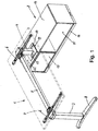
- Figure 1 shows a furniture combination with a table 1 and a box-shaped furniture body 2.
- the table 1 comprises a table frame with two vertical table legs 3, 4, which are connected to one another at the upper end by means of a horizontal longitudinal bar 5.
- cross members 6 are provided, which extend at right angles to the longitudinal spar 5.
- a table top 7 is attached, which in Figure 1 is only shown in dash-dotted lines to reveal the parts underneath.
- the two table legs 3, 4 have a rectangular cross section.
- the table leg 3, which is removed from the furniture body 2, is secured against tilting on an elongated base 8 which extends parallel to the cross members 6.
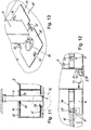
- the opposite table leg 4 extends, however, as from the Figures 11 and 12 can be seen, vertically through the furniture body 2 through to the floor on which the furniture body 2 is also located.
- the height of the table leg 4 can, as from the Figures 11 and 12 can be seen, can be varied by means of a height-adjustable element 9 attached to the lower end of the table leg 4.
- This height adjustment element 9 comprises, in a known manner, a support head 10 which can be placed on the floor and a vertical threaded bolt 11 which extends more or less into a threaded bore 12 can be screwed in, which is located in a base profile 13 of the table leg 4.
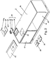
- the box-shaped furniture body 2 has the shape of a sideboard, the height of which is significantly less than the height of the table.
- the furniture body 2 comprises an upper horizontal furniture plate 14, which forms the ceiling plate of the furniture body 2.
- the furniture body 2 comprises a lower horizontal furniture plate 15, which forms the bottom of the furniture body 2.
- the lower furniture plate 15 is arranged by means of peripheral skirting boards 16 at a distance from the floor.
- a partial area of the furniture body 2 is furthermore closed or closable by means of a front cover or a door 17, in particular a sliding door.
- the upper furniture plate 14 has a recess which forms a passage opening 18 through which the table leg 4 extends.
- the passage opening 18 has a rectangular shape. Other shapes, such as oval shapes, are also possible.
- the passage opening 18 is substantially larger than the cross section of the table leg 4 passed through it.
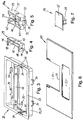
- a support device 19 is inserted into the passage opening 18, as in FIGS Figures 8 to 10 shown.
- the support device 19 comprises a rectangular frame 20.
- the frame 20 is expediently a plastic part.
- the frame 20 comprises outer edge profiles 21 which form a closed outer ring.
- the edge profiles 21 essentially have an L-shaped cross section with a vertical profile leg 22 and an upper horizontal profile leg 23 which projects outwards beyond the vertical profile leg 22.
- the vertical profile legs 22 can be inserted into the passage opening 18 with little play until the horizontal profile legs 23 rest on the top of the upper furniture plate 14.
- a latching of the frame 20 upwards is achieved by resilient clips 24 which project outwards at the lower end of two diametrically opposed vertical profile legs 22 and engage under the upper furniture plate 14 when the frame 20 is in the inserted state.
- the clips 24 are expediently formed in one piece on the vertical profile legs 22.
- the space enclosed by the outer edge profiles 21 is divided by a frame intermediate web 25 into two rectangular areas or spaces, so that a first rectangular space 26 and a second rectangular space 27 are formed.
- the first room 26 is slightly larger than the second room 27.
- the first room 26 is used to lead the table leg 4 through, while the second room 27 creates an additional space to in particular to be able to pass cables through the furniture panel 14.
- the first space 26 is larger than the cross section of the table leg 4, so that it is at a distance from the walls of the first space 26, i.e. at a distance from the outer edge profiles 21 and the frame intermediate web 25 can be arranged.
- first support jaws 28 In order to be able to transmit lateral forces from the table leg 4 to the frame 20 and thus to the furniture body 2 despite this distance, an in Figure 5 shown first support jaws 28 and a in Figure 4 shown second support jaws 29 used.
- the first support jaw 28 is, as will be explained in more detail later, supported on a first support wall 30, which is formed by an outer edge profile 21, with an adjustable distance from this first support wall 30.
- the second support jaw 29 is arranged in the immediate vicinity of a second support wall 31, which is also formed by an outer edge profile 21 and is diametrically opposite the first support wall 30.
- the first support jaw 28 has a jaw body 28a with an essentially cuboid outer contour.
- the width of the first support jaw 28 is dimensioned such that it can be inserted from above with little play between the intermediate frame web 25 and the diametrically opposite outer edge profile 21.
- the height position of the first support jaw 28 within the frame 20 is determined by edge-side webs 32 of the frame 20, which are from the intermediate frame web 25 and from the opposite one Edge profile 21 protrude inwards, ie into the first passage area 26. Shoulder regions 33 of the jaw body 28a can be placed on both of these horizontal webs 32.
- the webs 32 of the frame 20 form guide rails on which the first jaw body 28a can be moved in a sled-like manner relative to the first support wall 30.
- a resilient clip 34 is arranged on the two opposite side walls of the first support jaw 28. In the inserted state of the first support jaw 28, these clips 34 engage under the webs 32 of the frame 20 and thus prevent the first support jaw 28 from being lifted up unintentionally. The clips 34 thus form a snap connection, which enables the first support jaw 28 to be simply inserted into the frame 20 from above and to be latched in the vertical direction.
- a support element 36 in the form of a screw is used, which can be screwed from the side of the wall 35 to a different extent into a threaded sleeve 37 arranged centrally in the jaw body 28a such that a screw head 38 differs protrudes far beyond wall 35.
- the screw head 38 is supported on the first support wall 30, in particular on a vertical reinforcement web 39 of the first support wall 30.
- the support element 36 enables this A variable positioning of the support jaw 28 within the first passage area 26 and thus an adaptation to different cross sections of the table leg 4.
- the first support jaw 28 has at its end opposite the wall 35, which is designed to rest against the table leg 4, a first support section 40, which runs parallel to the wall 35 and thus to the first support wall 30 of the frame 20, and second and third support sections 41 , 42, which project in the direction of the table leg 4 over the first support section 40.
- the distance between the shoulders, which are formed between the first support section 40 and the second or third support section 41, 42, corresponds to the width of the table leg 4, so that the second and third support sections 41, 42 without play or with very little play around them Corners of the table leg 4 are passed around.
- the first, second and third support sections 40, 41, 42 thus form a three-sided support for the table leg 4 in the frame 20.
- the first support jaw 28 is expediently formed by a plastic part. Furthermore, it is expedient to design the first support jaw 28 at least predominantly as a weight-reduced hollow body, in which, however, reinforcement walls, bridges or webs can be present in order to avoid deformation.
- the second support jaw 29 has a substantially U-shaped shape.
- the second support jaw 29 can be inserted into the first space 26 of the frame 20 from above such that a wall 43 of the second support jaw 29 abuts the second support wall 31 of the frame 20.
- the width of the second support jaw 29 is dimensioned such that it is guided without play or with only very little lateral play between the frame intermediate web 25 and the diametrically opposite outer edge profile 21 of the frame 20.
- the height of the second support jaw 29 within the frame 20 is determined in the same or similar manner as in the first support jaw 28 by the lateral webs 32, on which laterally projecting shoulder areas 44 of the second support jaw 29 can be placed.
- the webs 32 can also merge into webs 32a, which are arranged in the region of the second support wall 31, in which case the shoulder regions 44 of the second support jaw 29 also extend along the wall 43, so that the second support jaw 29 on three sides on the Web 32, 32a is supported.
- the second support jaw 29 is in turn a plastic part which is at least essentially designed as a hollow part and can be stiffened by internal reinforcing webs or walls in order to prevent deformation.
- the second support jaw 29 has a first support section 47 which runs parallel to the second support wall 31 and, like the first support section 40 of the first support jaw 28, bears on the table leg 4 on the opposite side.
- first support section 47 On both sides of this first support section 47, second and third support sections 48, 49 protrude beyond the first support section 47, so that the second and third support sections 48, 49 extend around the corners of the table leg 4.
- the inner side walls of the second and third support sections 48, 49 rest against the corresponding side walls of the table leg 4 without play or with very little play.
- the first, second and third support sections 47, 48, 49 thus form a three-sided support for the table leg 4 in the frame 20.
- the support device 19 can further comprise a cover plate 50, with which the area between the table leg 4 and the frame 20 can be covered.
- This cover plate 50 is in Figure 6 shown in isolation. It has a recess 51 which is open on one side and through which the table leg 4 extends. Because the recess 51 is open on one side, the cover plate 50 can be pushed laterally onto the table leg 4 until the inner edge 52 of the recess 51 abuts the table leg 4.
- the open area behind the table leg 4 can be covered by a supplementary plate 50a, which is shown in FIG Figure 2 is shown.
- the width of the cutout 51 is dimensioned such that the table leg 4 can be inserted into the cutout 51 with only a small amount.
- the recess 51 is thus located above the first space 26 of the frame 20.
- the cover plate 50 also has a further recess 53 which, when the cover plate 50 is in the assembled state, lies above the second space 27 of the frame 20.
- the opening formed by the further recess 23 is smaller than the opening formed by the second space 27 and is used for the passage of cables, in particular data and electrical cables.
- the insert 54 shown can be inserted from above into the further recess 53 in order to further reduce it.
- This insert part 54 has a flat cover plate 55, which can preferably be inserted flush into the further recess 53.
- a transverse web 56 provided on the lower side of the cover plate 55 and projecting downwards creates an additional form-fitting hold within the further recess 53.
- the lower furniture plate 15 of the furniture body 2 has a further passage opening 57, which is arranged vertically below the upper passage opening 18.
- the table leg 4 extends through this further passage opening 57 down to the floor on which the furniture body 2 is also located.
- This further passage opening 57 is larger than the cross section of the table leg 4, so that there is a circumferential free space between the table leg 4 and the edge of the further passage opening 57.
- This free space can be covered by two insert elements 58, 59, which are clipped into the further passage opening 57 from above can be and together form a cover around the table leg 4.
- a passage opening 60 can be provided in the insert element 58, which is used in particular for the passage of cables, in particular data or electrical cables.
- the insert elements 58, 59 serve primarily to cover the free space around the table leg 4.
- the insert elements 58, 59 do not have to have a supporting function to the side, since lateral movements of the table leg 4 do not occur or only occur minimally in the area near the floor when the table experiences lateral forces in the upper area, ie via the table top 7. Rather, it is even expedient that the insert elements 58, 59 can yield a little laterally in order to adapt to the position of the table leg 4 used and to allow simple, tension-free assembly of the insert elements 58, 59.
- the clips 61 are expedient, as from Figure 12 visible, U-shaped, so that the outer legs of the clips 61 can retreat to the inside to a certain extent if necessary.
- the insert elements 58, 59 are in turn expediently each made of a one-piece plastic part.
- a support plate 62 which surrounds the passage opening 18 and which in particular consists of plastic or a metal sheet can be arranged on the upper furniture plate 14.
- This support plate 62 has a recess 63 which is designed and dimensioned such that the horizontal profile legs 23 of the frame 20 resting on the furniture plate 14 are only a short distance from the side edges of the recess 63.
- the cover plate 50 placed on the frame 20 also somewhat overlaps the support plate 62 on the edge.
Landscapes
- Tables And Desks Characterized By Structural Shape (AREA)
Claims (14)
- Meuble combiné comportant une table (1) et un corps de meuble (2) en forme de caisson, comprenant les éléments suivants :- le corps de meuble (2) comprend une plaque de meuble (14) dans laquelle est prévue une ouverture traversante (18),- la table (1) comprend un pied de table (4) mené à travers l'ouverture traversante (18),- le pied de table (4) est soutenu latéralement contre la plaque de meuble (14) au moyen d'un dispositif de soutien (19) à l'intérieur de l'ouverture traversante (18),- le dispositif de soutien (19) comprend un cadre (20) qui est inséré dans l'ouverture traversante (18) de la plaque de meuble (14),
caractérisé en ce que- un mors de soutien (28) comportant un corps de mors (28a) est disposé à l'intérieur d'un espace (26) entouré par le cadre (20), ledit corps étant soutenu d'une part contre une première paroi de soutien (30) du cadre (20) et d'autre part contre le pied de table (4). - Meuble combiné selon la revendication 1,
caractérisé en ce que
le corps de mors (28a) peut être soutenu sur le cadre (20) à différentes distances de la première paroi de soutien (30). - Meuble combiné selon la revendication 1 ou 2,
caractérisé en ce que
le mors de soutien (28) est guidé sur le cadre (20) de façon mobile en translation sur des barrettes (32) du cadre (20). - Meuble combiné selon l'une des revendications précédentes,
caractérisé en ce que
le mors de soutien (28) comprend au moins un élément de soutien (36) retenu sur le corps de mors (28a) et dépassant au-delà du corps de mors (28a) en direction de la première paroi de soutien (30), le dépassement de l'élément de soutien (36) au-delà du corps de mors (28a) étant réglable de façon variable. - Meuble combiné selon la revendication 4,
caractérisé en ce que
l'élément de soutien (36) est constitué d'une vis qui peut être vissée à des profondeurs différentes dans un perçage taraudé prévu sur le corps de mors (28a) et qui comprend une tête de vis (38) soutenue contre la première paroi de soutien (30). - Meuble combiné selon l'une des revendications précédentes,
caractérisé en ce que
le corps de mors (28a) comprend, au voisinage du pied de table (4), une première portion de soutien (40) s'étendant parallèlement à la première paroi de soutien (30) du cadre (20), une seconde et une troisième portions de soutien (41, 42) faisant saillie au-delà de la première portion de soutien (40) aux extrémités de la première portion de soutien (40), de telle sorte que les première, seconde et troisième portions de soutien (40, 41, 42) constituent un soutien sur trois côtés pour le pied de table (4) dans le cadre (20). - Meuble combiné selon l'une des revendications précédentes,
caractérisé en ce que
le mors de soutien (28) est un premiers mors de soutien et le dispositif de soutien (19) comprend un second mors de soutien (29) qui est disposé dans le cadre (20) et soutenu par une seconde paroi de soutien (31) du cadre (20), diamétralement opposée à la première paroi de soutien (30), de telle sorte que le pied de table (4) est disposé sans jeu entre le premier mors de soutien (28) et le second mors de soutien (29). - Meuble combiné selon la revendication 7,
caractérisé en ce que
le cadre (20) comprend des barrettes (32, 32a) sur lesquelles le second mors de soutien (29) peut être posé depuis le haut. - Meuble combiné selon la revendication 7 ou 8,
caractérisé en ce que
le second mors de soutien (29) comprend une première portion de soutien (47) qui s'étend parallèlement à la seconde paroi de soutien (31) du cadre (20), ainsi qu'une seconde et une troisième portion de soutien (48, 49) qui font saillie au-delà de la première portion de soutien (47) aux extrémités de la première portion de soutien (47), de telle sorte que la première, la seconde et la troisième portion de soutien (47, 48, 49) constituent un soutien sur trois côtés pour le pied de table (4) dans le cadre (20). - Meuble combiné selon l'une des revendications 7 à 9,
caractérisé en ce que
le cadre (20) entoure un premier et un second espace (26, 27) qui sont séparés l'un de l'autre par une barrette intermédiaire (25), le pied de table (4) étant mené à travers le premier espace (26), et le second espace (27) étant réalisé pour faire passer des câbles. - Meuble combiné selon la revendication 10,
caractérisé en ce que
une plaque de couverture (50) est disposée au-dessus du dispositif de soutien (19) et recouvre au moins partiellement le dispositif de soutien (19) et qui comprend une première échancrure (51) en forme de U, ouverte vers un côté, adaptée à la section transversale du pied de table (4) et susceptible d'être disposée au-dessus de l'espace (26) recevant le pied de table (4), et une autre échancrure (53) susceptible d'être disposée au-dessus du second espace (27). - Meuble combiné selon l'une des revendications précédentes,
caractérisé en ce que
le cadre (20) comprend des clips élastiques (24) faisant saillie latéralement vers l'extérieur et destinés à engager la plaque de meuble (14) par le dessous. - Meuble combiné selon l'une des revendications précédentes,
caractérisé en ce que
le corps de mors (28a) comprend des clips élastiques (34) faisant saillie latéralement vers l'extérieur et destinés à engager le cadre (20) par le dessous. - Meuble combiné selon l'une des revendications précédentes,
caractérisé en ce que
la plaque de meuble (14) présentant l'échancrure (18) est une plaque de dessus du corps de meuble (2), et le corps de meuble (2) présente une plaque de meuble (15) inférieure pourvue d'une autre ouverture traversante (57) pour le pied de table (4), le pied de table (4) s'étendant vers le bas jusqu'à un sol sur lequel repose le corps de meuble (2).
Applications Claiming Priority (1)
| Application Number | Priority Date | Filing Date | Title |
|---|---|---|---|
| PCT/IB2017/000028 WO2018134631A1 (fr) | 2017-01-20 | 2017-01-20 | Meuble combiné comportant une table et un corps de meuble en forme de caisson |
Publications (2)
| Publication Number | Publication Date |
|---|---|
| EP3554313A1 EP3554313A1 (fr) | 2019-10-23 |
| EP3554313B1 true EP3554313B1 (fr) | 2020-04-15 |
Family
ID=58191493
Family Applications (1)
| Application Number | Title | Priority Date | Filing Date |
|---|---|---|---|
| EP17707945.6A Active EP3554313B1 (fr) | 2017-01-20 | 2017-01-20 | Meuble combiné comportant une table et un corps de meuble en forme de caisson |
Country Status (3)
| Country | Link |
|---|---|
| EP (1) | EP3554313B1 (fr) |
| ES (1) | ES2800273T3 (fr) |
| WO (1) | WO2018134631A1 (fr) |
Family Cites Families (3)
| Publication number | Priority date | Publication date | Assignee | Title |
|---|---|---|---|---|
| JP5561907B2 (ja) * | 2008-03-07 | 2014-07-30 | 株式会社イトーキ | 机用キャビネット及び机とキャビネットとの組み合わせ家具 |
| CN202154255U (zh) * | 2011-06-20 | 2012-03-07 | 浙江圣奥家具制造有限公司 | 电动升降办公桌 |
| CN104433231A (zh) * | 2013-09-17 | 2015-03-25 | 李玉清 | 一种电脑桌 |
-
2017
- 2017-01-20 WO PCT/IB2017/000028 patent/WO2018134631A1/fr not_active Ceased
- 2017-01-20 EP EP17707945.6A patent/EP3554313B1/fr active Active
- 2017-01-20 ES ES17707945T patent/ES2800273T3/es active Active
Non-Patent Citations (1)
| Title |
|---|
| None * |
Also Published As
| Publication number | Publication date |
|---|---|
| WO2018134631A1 (fr) | 2018-07-26 |
| EP3554313A1 (fr) | 2019-10-23 |
| ES2800273T3 (es) | 2020-12-29 |
Similar Documents
| Publication | Publication Date | Title |
|---|---|---|
| AT414257B (de) | Halte- und einstellvorrichtung für bewegliche möbelteile | |
| EP3727090B1 (fr) | Paroi latérale de tiroir pourvu de profilé de couverture | |
| DE4240416B4 (de) | Versteifungsanordnung für einen Kraftfahrzeug-Aufbau mit einem Türträger | |
| EP3556978A1 (fr) | Dispositif de déplacement d'une partie de meuble logée sur une partie d'un meuble | |
| EP3561207B1 (fr) | Moyen de raccordement et partie de meuble | |
| WO2016177559A1 (fr) | Charnière de meuble dotée d'un amortisseur | |
| DE102007014795B4 (de) | Halteeinrichtung sowie Halteelement hierfür | |
| WO2018204956A1 (fr) | Commande de meuble à moteur | |
| EP2916686B1 (fr) | Élément de guidage coulissant et système de fixation de plateau de table pour la fixation coulissante d'un plateau de table | |
| EP2792830A2 (fr) | Élément de maintien d'une partie de ferrure | |
| WO2015074933A1 (fr) | Dispositif de retenue pour boîtier et procédé de montage du boîtier à l'aide du dispositif de retenue | |
| EP3768931B1 (fr) | Unité d'étanchéité | |
| DE202016106504U1 (de) | Montagewerkzeug für die Montage einer Schaltschranktür an einem Schaltschrankgehäuse und eine entsprechende Schaltschrankanordnung | |
| DE1945010B2 (de) | Scharnier fuer tueren, insbesondere aufschlagende tueren an moebeln und geraeten | |
| AT400660B (de) | Ausziehführungsgarnitur für eine schublade | |
| WO2018134631A1 (fr) | Meuble combiné comportant une table et un corps de meuble en forme de caisson | |
| EP3727091B1 (fr) | Arrangement comprenant une tringle et un element mural d'un tiroir | |
| EP2134306B1 (fr) | Grille latérale | |
| DE60301773T9 (de) | Verfahren und Gerät für die Montage eines Haushaltgeräts in einem Schrank | |
| DE202012103425U1 (de) | Bettlattenrost | |
| DE202007015750U1 (de) | Zusammenschiebbares Rohr für Werkzeuge | |
| EP3563009B1 (fr) | Dispositif de fixation de paravents servant à la fixation articulée de paravents et système de paravent | |
| AT406439B (de) | Ausziehvorrichtung für hochschränke | |
| DE202023100415U1 (de) | Eckverbinder mit Spreizelement | |
| DE20110531U1 (de) | Schublade |
Legal Events
| Date | Code | Title | Description |
|---|---|---|---|
| STAA | Information on the status of an ep patent application or granted ep patent |
Free format text: STATUS: UNKNOWN |
|
| STAA | Information on the status of an ep patent application or granted ep patent |
Free format text: STATUS: THE INTERNATIONAL PUBLICATION HAS BEEN MADE |
|
| PUAI | Public reference made under article 153(3) epc to a published international application that has entered the european phase |
Free format text: ORIGINAL CODE: 0009012 |
|
| STAA | Information on the status of an ep patent application or granted ep patent |
Free format text: STATUS: REQUEST FOR EXAMINATION WAS MADE |
|
| 17P | Request for examination filed |
Effective date: 20190626 |
|
| AK | Designated contracting states |
Kind code of ref document: A1 Designated state(s): AL AT BE BG CH CY CZ DE DK EE ES FI FR GB GR HR HU IE IS IT LI LT LU LV MC MK MT NL NO PL PT RO RS SE SI SK SM TR |
|
| AX | Request for extension of the european patent |
Extension state: BA ME |
|
| GRAP | Despatch of communication of intention to grant a patent |
Free format text: ORIGINAL CODE: EPIDOSNIGR1 |
|
| STAA | Information on the status of an ep patent application or granted ep patent |
Free format text: STATUS: GRANT OF PATENT IS INTENDED |
|
| DAV | Request for validation of the european patent (deleted) | ||
| DAX | Request for extension of the european patent (deleted) | ||
| INTG | Intention to grant announced |
Effective date: 20200102 |
|
| RAP1 | Party data changed (applicant data changed or rights of an application transferred) |
Owner name: STEELCASE INC. |
|
| GRAS | Grant fee paid |
Free format text: ORIGINAL CODE: EPIDOSNIGR3 |
|
| GRAA | (expected) grant |
Free format text: ORIGINAL CODE: 0009210 |
|
| STAA | Information on the status of an ep patent application or granted ep patent |
Free format text: STATUS: THE PATENT HAS BEEN GRANTED |
|
| AK | Designated contracting states |
Kind code of ref document: B1 Designated state(s): AL AT BE BG CH CY CZ DE DK EE ES FI FR GB GR HR HU IE IS IT LI LT LU LV MC MK MT NL NO PL PT RO RS SE SI SK SM TR |
|
| REG | Reference to a national code |
Ref country code: CH Ref legal event code: EP |
|
| REG | Reference to a national code |
Ref country code: DE Ref legal event code: R096 Ref document number: 502017004752 Country of ref document: DE |
|
| REG | Reference to a national code |
Ref country code: IE Ref legal event code: FG4D Free format text: LANGUAGE OF EP DOCUMENT: GERMAN |
|
| REG | Reference to a national code |
Ref country code: AT Ref legal event code: REF Ref document number: 1256282 Country of ref document: AT Kind code of ref document: T Effective date: 20200515 |
|
| REG | Reference to a national code |
Ref country code: NL Ref legal event code: MP Effective date: 20200415 |
|
| REG | Reference to a national code |
Ref country code: LT Ref legal event code: MG4D |
|
| PG25 | Lapsed in a contracting state [announced via postgrant information from national office to epo] |
Ref country code: FI Free format text: LAPSE BECAUSE OF FAILURE TO SUBMIT A TRANSLATION OF THE DESCRIPTION OR TO PAY THE FEE WITHIN THE PRESCRIBED TIME-LIMIT Effective date: 20200415 Ref country code: IS Free format text: LAPSE BECAUSE OF FAILURE TO SUBMIT A TRANSLATION OF THE DESCRIPTION OR TO PAY THE FEE WITHIN THE PRESCRIBED TIME-LIMIT Effective date: 20200815 Ref country code: GR Free format text: LAPSE BECAUSE OF FAILURE TO SUBMIT A TRANSLATION OF THE DESCRIPTION OR TO PAY THE FEE WITHIN THE PRESCRIBED TIME-LIMIT Effective date: 20200716 Ref country code: NO Free format text: LAPSE BECAUSE OF FAILURE TO SUBMIT A TRANSLATION OF THE DESCRIPTION OR TO PAY THE FEE WITHIN THE PRESCRIBED TIME-LIMIT Effective date: 20200715 Ref country code: LT Free format text: LAPSE BECAUSE OF FAILURE TO SUBMIT A TRANSLATION OF THE DESCRIPTION OR TO PAY THE FEE WITHIN THE PRESCRIBED TIME-LIMIT Effective date: 20200415 Ref country code: NL Free format text: LAPSE BECAUSE OF FAILURE TO SUBMIT A TRANSLATION OF THE DESCRIPTION OR TO PAY THE FEE WITHIN THE PRESCRIBED TIME-LIMIT Effective date: 20200415 Ref country code: PT Free format text: LAPSE BECAUSE OF FAILURE TO SUBMIT A TRANSLATION OF THE DESCRIPTION OR TO PAY THE FEE WITHIN THE PRESCRIBED TIME-LIMIT Effective date: 20200817 Ref country code: SE Free format text: LAPSE BECAUSE OF FAILURE TO SUBMIT A TRANSLATION OF THE DESCRIPTION OR TO PAY THE FEE WITHIN THE PRESCRIBED TIME-LIMIT Effective date: 20200415 |
|
| PG25 | Lapsed in a contracting state [announced via postgrant information from national office to epo] |
Ref country code: RS Free format text: LAPSE BECAUSE OF FAILURE TO SUBMIT A TRANSLATION OF THE DESCRIPTION OR TO PAY THE FEE WITHIN THE PRESCRIBED TIME-LIMIT Effective date: 20200415 Ref country code: BG Free format text: LAPSE BECAUSE OF FAILURE TO SUBMIT A TRANSLATION OF THE DESCRIPTION OR TO PAY THE FEE WITHIN THE PRESCRIBED TIME-LIMIT Effective date: 20200715 Ref country code: LV Free format text: LAPSE BECAUSE OF FAILURE TO SUBMIT A TRANSLATION OF THE DESCRIPTION OR TO PAY THE FEE WITHIN THE PRESCRIBED TIME-LIMIT Effective date: 20200415 Ref country code: HR Free format text: LAPSE BECAUSE OF FAILURE TO SUBMIT A TRANSLATION OF THE DESCRIPTION OR TO PAY THE FEE WITHIN THE PRESCRIBED TIME-LIMIT Effective date: 20200415 |
|
| PG25 | Lapsed in a contracting state [announced via postgrant information from national office to epo] |
Ref country code: AL Free format text: LAPSE BECAUSE OF FAILURE TO SUBMIT A TRANSLATION OF THE DESCRIPTION OR TO PAY THE FEE WITHIN THE PRESCRIBED TIME-LIMIT Effective date: 20200415 |
|
| REG | Reference to a national code |
Ref country code: DE Ref legal event code: R097 Ref document number: 502017004752 Country of ref document: DE |
|
| PG25 | Lapsed in a contracting state [announced via postgrant information from national office to epo] |
Ref country code: DK Free format text: LAPSE BECAUSE OF FAILURE TO SUBMIT A TRANSLATION OF THE DESCRIPTION OR TO PAY THE FEE WITHIN THE PRESCRIBED TIME-LIMIT Effective date: 20200415 Ref country code: IT Free format text: LAPSE BECAUSE OF FAILURE TO SUBMIT A TRANSLATION OF THE DESCRIPTION OR TO PAY THE FEE WITHIN THE PRESCRIBED TIME-LIMIT Effective date: 20200415 Ref country code: SM Free format text: LAPSE BECAUSE OF FAILURE TO SUBMIT A TRANSLATION OF THE DESCRIPTION OR TO PAY THE FEE WITHIN THE PRESCRIBED TIME-LIMIT Effective date: 20200415 Ref country code: EE Free format text: LAPSE BECAUSE OF FAILURE TO SUBMIT A TRANSLATION OF THE DESCRIPTION OR TO PAY THE FEE WITHIN THE PRESCRIBED TIME-LIMIT Effective date: 20200415 Ref country code: CZ Free format text: LAPSE BECAUSE OF FAILURE TO SUBMIT A TRANSLATION OF THE DESCRIPTION OR TO PAY THE FEE WITHIN THE PRESCRIBED TIME-LIMIT Effective date: 20200415 Ref country code: RO Free format text: LAPSE BECAUSE OF FAILURE TO SUBMIT A TRANSLATION OF THE DESCRIPTION OR TO PAY THE FEE WITHIN THE PRESCRIBED TIME-LIMIT Effective date: 20200415 |
|
| PLBE | No opposition filed within time limit |
Free format text: ORIGINAL CODE: 0009261 |
|
| STAA | Information on the status of an ep patent application or granted ep patent |
Free format text: STATUS: NO OPPOSITION FILED WITHIN TIME LIMIT |
|
| PG25 | Lapsed in a contracting state [announced via postgrant information from national office to epo] |
Ref country code: PL Free format text: LAPSE BECAUSE OF FAILURE TO SUBMIT A TRANSLATION OF THE DESCRIPTION OR TO PAY THE FEE WITHIN THE PRESCRIBED TIME-LIMIT Effective date: 20200415 Ref country code: SK Free format text: LAPSE BECAUSE OF FAILURE TO SUBMIT A TRANSLATION OF THE DESCRIPTION OR TO PAY THE FEE WITHIN THE PRESCRIBED TIME-LIMIT Effective date: 20200415 |
|
| 26N | No opposition filed |
Effective date: 20210118 |
|
| PG25 | Lapsed in a contracting state [announced via postgrant information from national office to epo] |
Ref country code: MC Free format text: LAPSE BECAUSE OF FAILURE TO SUBMIT A TRANSLATION OF THE DESCRIPTION OR TO PAY THE FEE WITHIN THE PRESCRIBED TIME-LIMIT Effective date: 20200415 |
|
| REG | Reference to a national code |
Ref country code: CH Ref legal event code: PL |
|
| PG25 | Lapsed in a contracting state [announced via postgrant information from national office to epo] |
Ref country code: LU Free format text: LAPSE BECAUSE OF NON-PAYMENT OF DUE FEES Effective date: 20210120 |
|
| REG | Reference to a national code |
Ref country code: BE Ref legal event code: MM Effective date: 20210131 |
|
| PG25 | Lapsed in a contracting state [announced via postgrant information from national office to epo] |
Ref country code: LI Free format text: LAPSE BECAUSE OF NON-PAYMENT OF DUE FEES Effective date: 20210131 Ref country code: CH Free format text: LAPSE BECAUSE OF NON-PAYMENT OF DUE FEES Effective date: 20210131 |
|
| PG25 | Lapsed in a contracting state [announced via postgrant information from national office to epo] |
Ref country code: IE Free format text: LAPSE BECAUSE OF NON-PAYMENT OF DUE FEES Effective date: 20210120 |
|
| PG25 | Lapsed in a contracting state [announced via postgrant information from national office to epo] |
Ref country code: BE Free format text: LAPSE BECAUSE OF NON-PAYMENT OF DUE FEES Effective date: 20210131 |
|
| REG | Reference to a national code |
Ref country code: AT Ref legal event code: MM01 Ref document number: 1256282 Country of ref document: AT Kind code of ref document: T Effective date: 20220120 |
|
| PG25 | Lapsed in a contracting state [announced via postgrant information from national office to epo] |
Ref country code: AT Free format text: LAPSE BECAUSE OF NON-PAYMENT OF DUE FEES Effective date: 20220120 |
|
| PG25 | Lapsed in a contracting state [announced via postgrant information from national office to epo] |
Ref country code: CY Free format text: LAPSE BECAUSE OF FAILURE TO SUBMIT A TRANSLATION OF THE DESCRIPTION OR TO PAY THE FEE WITHIN THE PRESCRIBED TIME-LIMIT Effective date: 20200415 |
|
| PG25 | Lapsed in a contracting state [announced via postgrant information from national office to epo] |
Ref country code: HU Free format text: LAPSE BECAUSE OF FAILURE TO SUBMIT A TRANSLATION OF THE DESCRIPTION OR TO PAY THE FEE WITHIN THE PRESCRIBED TIME-LIMIT; INVALID AB INITIO Effective date: 20170120 |
|
| PG25 | Lapsed in a contracting state [announced via postgrant information from national office to epo] |
Ref country code: SI Free format text: LAPSE BECAUSE OF FAILURE TO SUBMIT A TRANSLATION OF THE DESCRIPTION OR TO PAY THE FEE WITHIN THE PRESCRIBED TIME-LIMIT Effective date: 20200415 |
|
| PG25 | Lapsed in a contracting state [announced via postgrant information from national office to epo] |
Ref country code: MK Free format text: LAPSE BECAUSE OF FAILURE TO SUBMIT A TRANSLATION OF THE DESCRIPTION OR TO PAY THE FEE WITHIN THE PRESCRIBED TIME-LIMIT Effective date: 20200415 |
|
| PG25 | Lapsed in a contracting state [announced via postgrant information from national office to epo] |
Ref country code: MT Free format text: LAPSE BECAUSE OF FAILURE TO SUBMIT A TRANSLATION OF THE DESCRIPTION OR TO PAY THE FEE WITHIN THE PRESCRIBED TIME-LIMIT Effective date: 20200415 |
|
| PG25 | Lapsed in a contracting state [announced via postgrant information from national office to epo] |
Ref country code: TR Free format text: LAPSE BECAUSE OF FAILURE TO SUBMIT A TRANSLATION OF THE DESCRIPTION OR TO PAY THE FEE WITHIN THE PRESCRIBED TIME-LIMIT Effective date: 20200415 |
|
| PGFP | Annual fee paid to national office [announced via postgrant information from national office to epo] |
Ref country code: GB Payment date: 20260127 Year of fee payment: 10 |
|
| PGFP | Annual fee paid to national office [announced via postgrant information from national office to epo] |
Ref country code: ES Payment date: 20260202 Year of fee payment: 10 |
|
| PGFP | Annual fee paid to national office [announced via postgrant information from national office to epo] |
Ref country code: DE Payment date: 20260128 Year of fee payment: 10 |
|
| PGFP | Annual fee paid to national office [announced via postgrant information from national office to epo] |
Ref country code: FR Payment date: 20260126 Year of fee payment: 10 |