EP3554313B1 - Möbelkombination mit einem tisch und einem kastenförmigen möbelkorpus - Google Patents
Möbelkombination mit einem tisch und einem kastenförmigen möbelkorpus Download PDFInfo
- Publication number
- EP3554313B1 EP3554313B1 EP17707945.6A EP17707945A EP3554313B1 EP 3554313 B1 EP3554313 B1 EP 3554313B1 EP 17707945 A EP17707945 A EP 17707945A EP 3554313 B1 EP3554313 B1 EP 3554313B1
- Authority
- EP
- European Patent Office
- Prior art keywords
- support
- furniture
- frame
- jaw
- table leg
- Prior art date
- Legal status (The legal status is an assumption and is not a legal conclusion. Google has not performed a legal analysis and makes no representation as to the accuracy of the status listed.)
- Active
Links
Images

Classifications
-
- A—HUMAN NECESSITIES
- A47—FURNITURE; DOMESTIC ARTICLES OR APPLIANCES; COFFEE MILLS; SPICE MILLS; SUCTION CLEANERS IN GENERAL
- A47B—TABLES; DESKS; OFFICE FURNITURE; CABINETS; DRAWERS; GENERAL DETAILS OF FURNITURE
- A47B83/00—Combinations comprising two or more pieces of furniture of different kinds
- A47B83/04—Tables combined with other pieces of furniture
-
- A—HUMAN NECESSITIES
- A47—FURNITURE; DOMESTIC ARTICLES OR APPLIANCES; COFFEE MILLS; SPICE MILLS; SUCTION CLEANERS IN GENERAL
- A47B—TABLES; DESKS; OFFICE FURNITURE; CABINETS; DRAWERS; GENERAL DETAILS OF FURNITURE
- A47B9/00—Tables with tops of variable height
- A47B9/20—Telescopic guides
Definitions
- the invention relates to a furniture combination with a table and a box-shaped furniture body.
- CN202154255U discloses a furniture combination with a table and a box-shaped furniture body.
- the invention has for its object to provide a furniture combination which the above mentioned Avoids disadvantage and ensures good stability of the table.
- the furniture combination according to the invention has the advantage that the table leg passed through the passage opening can extend through the furniture plate to the floor, the table leg being on the side the furniture plate is supported. Vertical forces acting on the table leg can thus be transferred directly from the table leg to the floor. There is no vertical load on the top cover plate. This makes it unnecessary to reinforce the upper cover plate. Lateral forces acting on the table leg are also absorbed by the furniture body, which increases the stability of the table and minimizes lateral movements and vibrations of the table. Furthermore, with the help of the support jaw inserted into the frame, a simple, backlash-free or low-back support of the table leg is possible.
- the jaw body can preferably be supported on the frame at different distances from the first support wall. This makes it possible to easily adapt the side support of the table leg to different table leg cross sections without having to change the passage opening in the furniture plate and the support device.
- the support jaw is preferably slidably guided on the frame on webs or in grooves in the frame. This allows a simple adjustment of the support jaw within the frame.
- the support jaw is expediently designed as a slide which is guided on opposite sides, ie in its transverse direction, on the frame and is supported on one side on the frame in the direction of displacement.
- the support jaw preferably has at least one support element which is held on the jaw body and protrudes beyond the jaw body in the direction of the first support wall, the projection of the support element on the jaw body being variably adjustable. This makes it possible in a particularly simple manner to support the jaw body at different distances from the first retaining wall, to reduce the free space within the frame that remains for the passage of the table leg in the desired manner and to position the jaw body exactly next to the table leg.
- the support element preferably consists of a screw which can be screwed into a threaded hole provided on the jaw body to different extents and has a screw head which is supported on the first support wall. This enables the support position of the jaw body to be continuously adjusted within the frame in a particularly simple manner.
- the jaw body adjacent to the table leg includes a first support section that is parallel to the first support wall of the frame and second and third support sections that protrude beyond the first support section at the ends of the first support section such that the first, second and third support sections are one form three-sided support for the table leg in the frame.
- the first, second and third support sections form a U-shaped or C-shaped contact contour, which is expediently adapted to the outer contour of the table leg in such a way that it closely encloses the table leg on three sides.
- the table leg is not only in the direction of displacement of the support jaw, but also fixed in the transverse direction for this purpose within the frame by the support jaws.
- the support jaw is preferably a first support jaw and the support device has a second support jaw which is arranged in the frame and is supported by a second support wall of the frame, which is diametrically opposite the first support wall, in such a way that the table leg between the first support jaw and the second support jaw is arranged without play or at least with a lateral play smaller than 1 mm.
- the position of the free space through which the table leg is passed can also be varied within the frame.
- the frame preferably has webs on which the second support jaw can be placed from above. As a result, the second support jaw can be inserted and positioned in the frame in a particularly simple manner.
- the second support jaw includes a first support section that is parallel to the second support wall of the frame and second and third support sections that protrude beyond the first support section at the ends of the first support section such that the first, second and third support sections support on three sides form for the table leg in the frame.
- the first, second and third support sections of the second support jaw form a U-shaped or C-shaped outer contour, which is adapted to the cross-sectional shape of the table leg and can support the table leg on three sides. Together with the first support jaw, a square table leg can be supported over all four corner areas.
- the frame preferably surrounds first and second spaces, which are separated from one another by a frame intermediate web, the table leg being guided through the first space and the second space being designed for the passage of cables.
- a cover plate is arranged above the support device, with which the support device is at least partially covered and which comprises a U-shaped recess which is open on one side and which is adapted to the cross section of the table leg, and a further recess which is above the second , can be arranged for the passage of cables of certain space.
- a cover plate By means of such a cover plate, the entire frame around the table leg can be covered in such a way that only a cable passage remains next to the table leg.
- the cover plate can be installed in a simple manner.
- the frame preferably has resilient clips projecting laterally outwards for reaching under the furniture panel.
- the frame can be inserted from above into the passage opening of the furniture panel in a particularly simple manner, until one extends laterally outwards protruding edge of the frame rests on the furniture plate. The clips then prevent the frame from lifting upwards.
- the jaw body preferably has resilient clips projecting laterally outwards for reaching under the frame.
- the jaw body can be inserted into the frame from above in a particularly simple manner until it rests, for example, on projecting webs of the frame. The clips then prevent the jaw body from lifting upwards.
- the furniture plate having the recess is a cover plate of the furniture body and the furniture body has a lower furniture plate designed as a base plate with a further passage opening for the table leg, the table leg extending down to a floor on which the furniture body stands.
- the table leg extending down to a floor on which the furniture body stands.
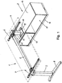
- Figure 1 shows a furniture combination with a table 1 and a box-shaped furniture body 2.
- the table 1 comprises a table frame with two vertical table legs 3, 4, which are connected to one another at the upper end by means of a horizontal longitudinal bar 5.
- cross members 6 are provided, which extend at right angles to the longitudinal spar 5.
- a table top 7 is attached, which in Figure 1 is only shown in dash-dotted lines to reveal the parts underneath.
- the two table legs 3, 4 have a rectangular cross section.
- the table leg 3, which is removed from the furniture body 2, is secured against tilting on an elongated base 8 which extends parallel to the cross members 6.
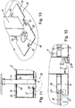
- the opposite table leg 4 extends, however, as from the Figures 11 and 12 can be seen, vertically through the furniture body 2 through to the floor on which the furniture body 2 is also located.
- the height of the table leg 4 can, as from the Figures 11 and 12 can be seen, can be varied by means of a height-adjustable element 9 attached to the lower end of the table leg 4.
- This height adjustment element 9 comprises, in a known manner, a support head 10 which can be placed on the floor and a vertical threaded bolt 11 which extends more or less into a threaded bore 12 can be screwed in, which is located in a base profile 13 of the table leg 4.
- the box-shaped furniture body 2 has the shape of a sideboard, the height of which is significantly less than the height of the table.
- the furniture body 2 comprises an upper horizontal furniture plate 14, which forms the ceiling plate of the furniture body 2.
- the furniture body 2 comprises a lower horizontal furniture plate 15, which forms the bottom of the furniture body 2.
- the lower furniture plate 15 is arranged by means of peripheral skirting boards 16 at a distance from the floor.
- a partial area of the furniture body 2 is furthermore closed or closable by means of a front cover or a door 17, in particular a sliding door.
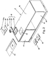
- the upper furniture plate 14 has a recess which forms a passage opening 18 through which the table leg 4 extends.
- the passage opening 18 has a rectangular shape. Other shapes, such as oval shapes, are also possible.
- the passage opening 18 is substantially larger than the cross section of the table leg 4 passed through it.
- a support device 19 is inserted into the passage opening 18, as in FIGS Figures 8 to 10 shown.
- the support device 19 comprises a rectangular frame 20.
- the frame 20 is expediently a plastic part.
- the frame 20 comprises outer edge profiles 21 which form a closed outer ring.
- the edge profiles 21 essentially have an L-shaped cross section with a vertical profile leg 22 and an upper horizontal profile leg 23 which projects outwards beyond the vertical profile leg 22.
- the vertical profile legs 22 can be inserted into the passage opening 18 with little play until the horizontal profile legs 23 rest on the top of the upper furniture plate 14.
- a latching of the frame 20 upwards is achieved by resilient clips 24 which project outwards at the lower end of two diametrically opposed vertical profile legs 22 and engage under the upper furniture plate 14 when the frame 20 is in the inserted state.
- the clips 24 are expediently formed in one piece on the vertical profile legs 22.
- the space enclosed by the outer edge profiles 21 is divided by a frame intermediate web 25 into two rectangular areas or spaces, so that a first rectangular space 26 and a second rectangular space 27 are formed.
- the first room 26 is slightly larger than the second room 27.
- the first room 26 is used to lead the table leg 4 through, while the second room 27 creates an additional space to in particular to be able to pass cables through the furniture panel 14.
- the first space 26 is larger than the cross section of the table leg 4, so that it is at a distance from the walls of the first space 26, i.e. at a distance from the outer edge profiles 21 and the frame intermediate web 25 can be arranged.
- first support jaws 28 In order to be able to transmit lateral forces from the table leg 4 to the frame 20 and thus to the furniture body 2 despite this distance, an in Figure 5 shown first support jaws 28 and a in Figure 4 shown second support jaws 29 used.
- the first support jaw 28 is, as will be explained in more detail later, supported on a first support wall 30, which is formed by an outer edge profile 21, with an adjustable distance from this first support wall 30.
- the second support jaw 29 is arranged in the immediate vicinity of a second support wall 31, which is also formed by an outer edge profile 21 and is diametrically opposite the first support wall 30.
- the first support jaw 28 has a jaw body 28a with an essentially cuboid outer contour.
- the width of the first support jaw 28 is dimensioned such that it can be inserted from above with little play between the intermediate frame web 25 and the diametrically opposite outer edge profile 21.
- the height position of the first support jaw 28 within the frame 20 is determined by edge-side webs 32 of the frame 20, which are from the intermediate frame web 25 and from the opposite one Edge profile 21 protrude inwards, ie into the first passage area 26. Shoulder regions 33 of the jaw body 28a can be placed on both of these horizontal webs 32.
- the webs 32 of the frame 20 form guide rails on which the first jaw body 28a can be moved in a sled-like manner relative to the first support wall 30.
- a resilient clip 34 is arranged on the two opposite side walls of the first support jaw 28. In the inserted state of the first support jaw 28, these clips 34 engage under the webs 32 of the frame 20 and thus prevent the first support jaw 28 from being lifted up unintentionally. The clips 34 thus form a snap connection, which enables the first support jaw 28 to be simply inserted into the frame 20 from above and to be latched in the vertical direction.
- a support element 36 in the form of a screw is used, which can be screwed from the side of the wall 35 to a different extent into a threaded sleeve 37 arranged centrally in the jaw body 28a such that a screw head 38 differs protrudes far beyond wall 35.
- the screw head 38 is supported on the first support wall 30, in particular on a vertical reinforcement web 39 of the first support wall 30.
- the support element 36 enables this A variable positioning of the support jaw 28 within the first passage area 26 and thus an adaptation to different cross sections of the table leg 4.
- the first support jaw 28 has at its end opposite the wall 35, which is designed to rest against the table leg 4, a first support section 40, which runs parallel to the wall 35 and thus to the first support wall 30 of the frame 20, and second and third support sections 41 , 42, which project in the direction of the table leg 4 over the first support section 40.
- the distance between the shoulders, which are formed between the first support section 40 and the second or third support section 41, 42, corresponds to the width of the table leg 4, so that the second and third support sections 41, 42 without play or with very little play around them Corners of the table leg 4 are passed around.
- the first, second and third support sections 40, 41, 42 thus form a three-sided support for the table leg 4 in the frame 20.
- the first support jaw 28 is expediently formed by a plastic part. Furthermore, it is expedient to design the first support jaw 28 at least predominantly as a weight-reduced hollow body, in which, however, reinforcement walls, bridges or webs can be present in order to avoid deformation.
- the second support jaw 29 has a substantially U-shaped shape.
- the second support jaw 29 can be inserted into the first space 26 of the frame 20 from above such that a wall 43 of the second support jaw 29 abuts the second support wall 31 of the frame 20.
- the width of the second support jaw 29 is dimensioned such that it is guided without play or with only very little lateral play between the frame intermediate web 25 and the diametrically opposite outer edge profile 21 of the frame 20.
- the height of the second support jaw 29 within the frame 20 is determined in the same or similar manner as in the first support jaw 28 by the lateral webs 32, on which laterally projecting shoulder areas 44 of the second support jaw 29 can be placed.
- the webs 32 can also merge into webs 32a, which are arranged in the region of the second support wall 31, in which case the shoulder regions 44 of the second support jaw 29 also extend along the wall 43, so that the second support jaw 29 on three sides on the Web 32, 32a is supported.
- the second support jaw 29 is in turn a plastic part which is at least essentially designed as a hollow part and can be stiffened by internal reinforcing webs or walls in order to prevent deformation.
- the second support jaw 29 has a first support section 47 which runs parallel to the second support wall 31 and, like the first support section 40 of the first support jaw 28, bears on the table leg 4 on the opposite side.
- first support section 47 On both sides of this first support section 47, second and third support sections 48, 49 protrude beyond the first support section 47, so that the second and third support sections 48, 49 extend around the corners of the table leg 4.
- the inner side walls of the second and third support sections 48, 49 rest against the corresponding side walls of the table leg 4 without play or with very little play.
- the first, second and third support sections 47, 48, 49 thus form a three-sided support for the table leg 4 in the frame 20.
- the support device 19 can further comprise a cover plate 50, with which the area between the table leg 4 and the frame 20 can be covered.
- This cover plate 50 is in Figure 6 shown in isolation. It has a recess 51 which is open on one side and through which the table leg 4 extends. Because the recess 51 is open on one side, the cover plate 50 can be pushed laterally onto the table leg 4 until the inner edge 52 of the recess 51 abuts the table leg 4.
- the open area behind the table leg 4 can be covered by a supplementary plate 50a, which is shown in FIG Figure 2 is shown.
- the width of the cutout 51 is dimensioned such that the table leg 4 can be inserted into the cutout 51 with only a small amount.
- the recess 51 is thus located above the first space 26 of the frame 20.
- the cover plate 50 also has a further recess 53 which, when the cover plate 50 is in the assembled state, lies above the second space 27 of the frame 20.
- the opening formed by the further recess 23 is smaller than the opening formed by the second space 27 and is used for the passage of cables, in particular data and electrical cables.
- the insert 54 shown can be inserted from above into the further recess 53 in order to further reduce it.
- This insert part 54 has a flat cover plate 55, which can preferably be inserted flush into the further recess 53.
- a transverse web 56 provided on the lower side of the cover plate 55 and projecting downwards creates an additional form-fitting hold within the further recess 53.
- the lower furniture plate 15 of the furniture body 2 has a further passage opening 57, which is arranged vertically below the upper passage opening 18.
- the table leg 4 extends through this further passage opening 57 down to the floor on which the furniture body 2 is also located.
- This further passage opening 57 is larger than the cross section of the table leg 4, so that there is a circumferential free space between the table leg 4 and the edge of the further passage opening 57.
- This free space can be covered by two insert elements 58, 59, which are clipped into the further passage opening 57 from above can be and together form a cover around the table leg 4.
- a passage opening 60 can be provided in the insert element 58, which is used in particular for the passage of cables, in particular data or electrical cables.
- the insert elements 58, 59 serve primarily to cover the free space around the table leg 4.
- the insert elements 58, 59 do not have to have a supporting function to the side, since lateral movements of the table leg 4 do not occur or only occur minimally in the area near the floor when the table experiences lateral forces in the upper area, ie via the table top 7. Rather, it is even expedient that the insert elements 58, 59 can yield a little laterally in order to adapt to the position of the table leg 4 used and to allow simple, tension-free assembly of the insert elements 58, 59.
- the clips 61 are expedient, as from Figure 12 visible, U-shaped, so that the outer legs of the clips 61 can retreat to the inside to a certain extent if necessary.
- the insert elements 58, 59 are in turn expediently each made of a one-piece plastic part.
- a support plate 62 which surrounds the passage opening 18 and which in particular consists of plastic or a metal sheet can be arranged on the upper furniture plate 14.
- This support plate 62 has a recess 63 which is designed and dimensioned such that the horizontal profile legs 23 of the frame 20 resting on the furniture plate 14 are only a short distance from the side edges of the recess 63.
- the cover plate 50 placed on the frame 20 also somewhat overlaps the support plate 62 on the edge.
Landscapes
- Tables And Desks Characterized By Structural Shape (AREA)
Description
- Die Erfindung betrifft eine Möbelkombination mit einem Tisch und einem kastenförmigen Möbelkorpus.
- Es ist bekannt, einen Tisch mit einem kastenförmigen Möbelkorpus, beispielsweise einem Sideboard, dadurch miteinander zu kombinieren und zu verbinden, dass ein entsprechend verkürztes Tischbein auf die obere Deckelplatte des Möbelkorpus aufgeschraubt wird. Hierdurch ist es möglich, den Möbelkorpus in einen Bereich unterhalb des Tisches hinein zu verlagern, in dem sich der Tischfuß befindet. Nachteilig ist hierbei, dass die obere Deckelplatte des Möbelkorpus, auf welcher sich das Tischbein abstützt, sehr massiv ausgebildet werden muss, um den vom Tischbein ausgeübten Druck beschädigungsfrei und ohne Durchbiegung aufnehmen zu können.
-
CN202154255U offenbart eine Möbelkombination mit einem Tisch und einem kastenförmigen Möbelkorpus. - Der Erfindung liegt die Aufgabe zugrunde, eine Möbelkombination zu schaffen, welche den vorstehend erwähnten Nachteil vermeidet und eine gute Standfestigkeit des Tisches gewährleistet.
- Diese Aufgabe wird erfindungsgemäß durch eine Möbelkombination mit den Merkmalen des Anspruches 1 gelöst. Vorteilhafte Ausführungsformen der Erfindung sind in den Unteransprüchen beschrieben.
- Die erfindungsgemäße Möbelkombination weist folgende Merkmale auf:
- Der Möbelkorpus weist eine Möbelplatte auf, in der eine Durchtrittsöffnung vorgesehen ist,
- der Tisch weist ein Tischbein auf, das durch die Durchtrittsöffnung der Möbelplatte hindurchgeführt ist,
- das Tischbein ist innerhalb der Durchtrittsöffnung mittels einer Stützvorrichtung seitlich gegen die Möbelplatte abgestützt,
- die Stützvorrichtung weist einen Rahmen auf, der in die Durchtrittsöffnung der Möbelplatte eingesetzt ist, und
- innerhalb eines vom Rahmen umschlossenen Raums ist zumindest ein Stützbacken mit einem Backenkörper angeordnet, der einerseits an einer ersten Stützwand des Rahmens und andererseits am Tischbein abgestützt ist.
- Die erfindungsgemäße Möbelkombination hat den Vorteil, dass sich das durch die Durchtrittsöffnung hindurchgeführte Tischbein durch die Möbelplatte hindurch bis zum Boden erstrecken kann, wobei das Tischbein seitlich an der Möbelplatte abgestützt wird. Auf das Tischbein einwirkende Vertikalkräfte können somit direkt vom Tischbein auf den Boden übertragen werden. Eine Vertikalbelastung der oberen Deckelplatte entfällt. Hierdurch erübrigt sich eine Verstärkung der oberen Deckelplatte. Auf das Tischbein einwirkende Seitenkräfte werden dabei zusätzlich vom Möbelkorpus aufgenommen, was die Standfestigkeit des Tisches erhöht und seitliche Bewegungen und Schwingungen des Tisches minimiert. Weiterhin ist mit Hilfe des in den Rahmen eingesetzten Stützbackens eine einfache spielfreie oder spielarme seitliche Abstützung des Tischbeins möglich.
- Vorzugsweise ist der Backenkörper in verschiedenen Abständen zur ersten Stützwand am Rahmen abstützbar. Hierdurch ist es möglich, die Seitenabstützung des Tischbeins auf einfache Weise an unterschiedliche Tischbeinquerschnitte anzupassen, ohne die Durchtrittsöffnung in der Möbelplatte und die Stützvorrichtung ändern zu müssen.
- Vorzugsweise ist der Stützbacken auf Stegen oder in Nuten des Rahmens verschiebbar am Rahmen geführt. Dies ermöglicht auf einfache Weise eine stufenlose Verstellung des Stützbackens innerhalb des Rahmens. Der Stützbacken ist hierbei zweckmäßigerweise als Schlitten ausgeführt, der auf gegenüberliegenden Seiten, d.h. in seiner Querrichtung, am Rahmen geführt ist und in Verschieberichtung einseitig am Rahmen abgestützt ist. Alternativ hierzu ist es auch denkbar, den Stützbacken und den Rahmen derart auszubilden, dass der Stützbacken in mehreren unterschiedlichen Rastpositionen am Rahmen verankert werden kann.
- Vorzugsweise weist der Stützbacken mindestens ein am Backenkörper gehaltertes Stützelement auf, das in Richtung der ersten Stützwand über den Backenkörper übersteht, wobei der Überstand des Stützelements am Backenkörper variabel einstellbar ist. Hierdurch ist es auf besonders einfache Art und Weise möglich, den Backenkörper in unterschiedlichen Abständen zur ersten Stützwand abzustützen, den Freiraum innerhalb des Rahmens, der zum Hindurchführen des Tischbeins verbleibt, in der gewünschten Weise zu verkleinern und den Backenkörper genau neben dem Tischbein zu positionieren.
- Vorzugsweise besteht das Stützelement aus einer Schraube, die in eine am Backenkörper vorgesehene Gewindebohrung unterschiedlich weit einschraubbar ist und einen Schraubenkopf aufweist, der an der ersten Stützwand abgestützt ist. Dies ermöglicht auf besonders einfache Weise eine stufenlose Verstellung der Abstützposition des Backenkörpers innerhalb des Rahmens.
- Vorzugsweise umfasst der Backenkörper benachbart zum Tischbein einen ersten Stützabschnitt, der parallel zur ersten Stützwand des Rahmens verläuft, und zweite und dritte Stützabschnitte, die an den Enden des ersten Stützabschnitts über den ersten Stützabschnitt vorragen, derart, dass die ersten, zweiten und dritten Stützabschnitte eine dreiseitige Abstützung für das Tischbein im Rahmen bilden. Die ersten, zweiten und dritten Stützabschnitte bilden auf diese Weise eine U- oder C-förmige Anlagekontur, die zweckmäßigerweise an die Außenkontur des Tischbeins derart angepasst ist, dass sie das Tischbein auf drei Seiten eng umschließt. Hierdurch wird das Tischbein nicht nur in Verschieberichtung des Stützbackens, sondern auch in Querrichtung hierzu innerhalb des Rahmens durch den Stützbacken fixiert.
- Vorzugsweise ist der Stützbacken ein erster Stützbacken und die Stützvorrichtung weist einen zweiten Stützbacken auf, der derart im Rahmen angeordnet und von einer zweiten Stützwand des Rahmens, welche der ersten Stützwand diametral gegenüberliegt, abgestützt ist, dass das Tischbein zwischen dem ersten Stützbacken und dem zweiten Stützbacken spielfrei oder zumindest mit einem kleineren seitlichen Spiel als 1 mm angeordnet ist. Mit Hilfe des zweiten Stützbackens lässt sich die Position des Freiraums, durch den das Tischbein hindurchgeführt ist, innerhalb des Rahmens zusätzlich variieren. Alternativ hierzu ist es jedoch auch möglich, lediglich einen einzigen Stützbacken vorzusehen, um das Tischbein auf einer Seite abzustützen, während die andere Seite des Tischbeins direkt durch den Rahmen abgestützt wird.
- Vorzugsweise weist der Rahmen Stege auf, auf welche der zweite Stützbacken von oben her aufsetzbar ist. Hierdurch kann der zweite Stützbacken auf besonders einfache Weise in den Rahmen eingesetzt und positioniert werden.
- Vorzugsweise umfasst der zweite Stützbacken einen ersten Stützabschnitt, der parallel zur zweiten Stützwand des Rahmens verläuft, und zweite und dritte Stützabschnitte, die an den Enden des ersten Stützabschnitts über den ersten Stützabschnitt vorragen, derart, dass die ersten, zweiten und dritten Stützabschnitte eine dreiseitige Abstützung für das Tischbein im Rahmen bilden. Die ersten, zweiten und dritten Stützabschnitte des zweiten Stützbackens bilden hierbei eine U- oder C-förmige Außenkontur, die an die Querschnittsform des Tischbein angepasst ist und das Tischbein an drei Seiten abstützen kann. Zusammen mit dem ersten Stützbacken kann auf diese Weise ein viereckiges Tischbein über alle vier Eckenbereiche abgestützt werden.
- Vorzugsweise umschließt der Rahmen erste und zweite Räume, die durch einen Rahmenzwischensteg voneinander getrennt sind, wobei das Tischbein durch den ersten Raum hindurchgeführt ist und der zweite Raum zum Hindurchführen von Kabeln ausgebildet ist. Hierdurch ist es auf besonders einfache Weise möglich, Kabel, beispielsweise Elektro- oder Datenkabel, neben dem Tischbein durch die Möbelplatte hindurchzuführen.
- Vorzugsweise ist oberhalb der Stützvorrichtung eine Abdeckplatte angeordnet, mit der die Stützvorrichtung zumindest teilweise abgedeckt ist und die eine U-förmige, zu einer Seite hin offene Aussparung, die an den Querschnitt des Tischbeins angepasst ist, und eine weitere Aussparung umfasst, die oberhalb des zweiten, zum Hindurchführen von Kabeln bestimmten Raums anordenbar ist. Mittels einer derartigen Abdeckplatte kann der gesamte Rahmen um das Tischbein herum auf gefällige Weise derart abgedeckt werden, dass lediglich neben dem Tischbein ein Kabeldurchlass verbleibt. Weiterhin kann die Abdeckplatte auf einfache Weise montiert werden.
- Vorzugsweise weist der Rahmen seitlich nach außen vorstehende, federnde Clips zum Untergreifen der Möbelplatte auf. Hierdurch kann der Rahmen auf besonders einfache Weise von oben her in die Durchtrittsöffnung der Möbelplatte eingesetzt werden, bis ein seitlich nach außen vorstehender Rand des Rahmens auf der Möbelplatte aufliegt. Die Clips verhindern dann ein Abheben des Rahmens nach oben.
- Vorzugsweise weist der Backenkörper seitlich nach außen vorstehende, federnde Clips zum Untergreifen des Rahmens auf. Hierdurch kann der Backenkörper auf besonders einfache Weise von oben her in den Rahmen eingesetzt werden, bis er beispielsweise auf vorspringenden Stegen des Rahmens aufliegt. Die Clips verhindern dann ein Abheben des Backenkörpers nach oben.
- Vorzugsweise ist die die Aussparung aufweisende Möbelplatte eine Deckelplatte des Möbelkorpus und der Möbelkorpus weist eine als Bodenplatte ausgebildete untere Möbelplatte mit einer weiteren Durchtrittsöffnung für das Tischbein auf, wobei sich das Tischbein nach unten bis zu einem Boden erstreckt, auf dem der Möbelkorpus steht. Auf diese Weise werden vom Tischbein keinerlei Vertikalkräfte auf den Möbelkorpus aufgebracht. Alternativ hierzu ist es jedoch auch denkbar, das Tischbein lediglich durch die Deckelplatte des Möbelkorpus und gegebenenfalls auch durch Zwischenplatten hindurchzuführen und das Tischbein auf einer Bodenplatte des Möbelkorpus aufsitzen zu lassen.
- Die Erfindung wird nachfolgend anhand der Zeichnungen näher erläutert. Es zeigen:
- Figur 1:
- eine erfindungsgemäße Möbelkombination mit einem Tisch und einem kastenförmigen Möbelkorpus schräg von oben,
- Figur 2:
- den Möbelkorpus von
Figur 1 mit einer Stützeinrichtung, die in Explosionsdarstellung gezeigt ist, - Figur 3:
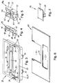
- einen Rahmen der Stützeinrichtung in Alleinstellung,
- Figur 4:
- einen zweiten Stützbacken,
- Figur 5:
- einen ersten Stützbacken,
- Figur 6:
- eine Abdeckplatte,
- Figur 7:
- ein Einsetzteil für die Abdeckplatte von
Figur 6 , - Figur 8:
- einen Blick auf die montierte Stützvorrichtung mit hindurchgeführtem Tischbein schräg von oben,
- Figur 9:
- eine Darstellung gemäß
Figur 8 , jedoch von einer anderen Seite her, - Figur 10:
- eine Ansicht schräg von unten auf die montierte Stützvorrichtung mit hindurchgeführtem Tischbein,
- Figur 11:
- einen Vertikalschnitt durch den Möbelkorpus im Bereich des hindurchgeführten Tischbeins,
- Figur 12:
- die Einzelheit XII von
Figur 11 , und - Figur 13:
- eine Ansicht schräg von oben auf eine untere Durchführung des Möbelkorpus, durch den sich das Tischbein hindurch erstreckt.
-
Figur 1 zeigt eine Möbelkombination mit einem Tisch 1 und einem kastenförmigen Möbelkorpus 2. Der Tisch 1 umfasst ein Tischgestell mit zwei vertikalen Tischbeinen 3, 4, die am oberen Ende mittels eines horizontalen Längsholms 5 miteinander verbunden sind. In den beiden Übergangsbereichen zwischen dem Längsholm 5 und den Tischbeinen 3, 4 sind Querträger 6 vorgesehen, die sich rechtwinklig zum Längsholm 5 erstrecken. Auf den Querträgern 6 ist eine Tischplatte 7 befestigt, die inFigur 1 lediglich strichpunktiert eingezeichnet ist, um die Sicht auf darunter liegenden Teile freizugeben. - Die beiden Tischbeine 3, 4 haben einen rechteckigen Querschnitt. Das vom Möbelkorpus 2 entfernte Tischbein 3 ist auf einem länglichen bodenseitigen Tischfuß 8 kippsicher befestigt, der sich parallel zu den Querträgern 6 erstreckt. Das gegenüberliegende Tischbein 4 erstreckt sich dagegen, wie aus den
Figuren 11 und 12 ersichtlich, vertikal durch den Möbelkorpus 2 hindurch bis zum Boden, auf dem sich auch der Möbelkorpus 2 befindet. - Die Höhe des Tischbeins 4 kann dabei, wie aus den
Figuren 11 und 12 ersichtlich, mittels eines höhenverstellbar am unteren Ende des Tischbeins 4 befestigten Höheneinstellelements 9 variiert werden. Dieses Höheneinstellelement 9 umfasst in bekannter Weise einen auf den Boden aufsetzbaren Auflagekopf 10 und einen vertikalen Gewindebolzen 11, der mehr oder weniger weit in eine Gewindebohrung 12 einschraubbar ist, die sich in einem Bodenprofil 13 des Tischbeins 4 befindet. - Der kastenförmige Möbelkorpus 2 hat im gezeigten Ausführungsbeispiel die Form eines Sideboards, dessen Höhe deutlich geringer ist als die Höhe des Tisches. Der Möbelkorpus 2 umfasst eine obere horizontale Möbelplatte 14, welche die Deckenplatte des Möbelkorpus 2 bildet. Bodenseitig umfasst der Möbelkorpus 2 eine untere horizontale Möbelplatte 15, welche den Boden des Möbelkorpus 2 bildet. Die untere Möbelplatte 15 ist mittels umlaufender Bodenleisten 16 mit etwas Abstand zum Boden angeordnet. Im gezeigten Ausführungsbeispiel ist weiterhin ein Teilbereich des Möbelkorpus 2 mittels einer vorderen Abdeckung oder einer Tür 17, insbesondere Schiebetür, verschlossen oder verschließbar.
- Aus
Figur 2 ist ersichtlich, dass die obere Möbelplatte 14 eine Aussparung aufweist, die eine Durchtrittsöffnung 18 bildet, durch die sich das Tischbein 4 hindurch erstreckt. Im gezeigten Ausführungsbeispiel hat die Durchtrittsöffnung 18 eine rechteckige Form. Andere Formen, beispielsweise ovale Formen, sind ebenfalls möglich. Die Durchtrittsöffnung 18 ist wesentlich größer als der Querschnitt des hindurchgeführten Tischbeins 4. - Um trotz des zwischen dem Tischbein 4 und dem Rand der Durchtrittsöffnung 18 vorhandenen Abstandes Seitenkräfte, die auf das Tischbein 4 einwirken, auf den Möbelkorpus 2 übertragen zu können, ist in die Durchtrittsöffnung 18 eine Stützvorrichtung 19 eingesetzt, wie in den
Figuren 8 bis 10 dargestellt. - Wesentliche Teile dieser Stützvorrichtung 19 werden im Folgenden anhand der
Figuren 3 bis 5 näher erläutert. - Wie aus
Figur 3 ersichtlich, umfasst die Stützvorrichtung 19 einen rechteckförmigen Rahmen 20. Zweckmäßigerweise handelt es sich beim Rahmen 20 um ein Kunststoffteil. Der Rahmen 20 umfasst äußere Randprofile 21, die einen geschlossenen äußeren Ring bilden. Die Randprofile 21 haben im Wesentlichen einen L-förmigen Querschnitt mit einem vertikalen Profilschenkel 22 und einem oberen horizontalen Profilschenkel 23, der über den vertikalen Profilschenkel 22 nach außen vorsteht. Die vertikalen Profilschenkel 22 können mit geringem Spiel von oben her in die Durchtrittsöffnung 18 eingesetzt werden, bis die horizontalen Profilschenkel 23 auf der Oberseite der oberen Möbelplatte 14 aufliegen. Eine Verrastung des Rahmens 20 nach oben wird dabei durch federnde Clips 24 erreicht, die am unteren Ende von zwei diametral gegenüberliegenden vertikalen Profilschenkeln 22 nach außen vorstehen und die obere Möbelplatte 14 im eingesetzten Zustand des Rahmens 20 untergreifen. Zweckmäßigerweise sind die Clips 24 an die vertikalen Profilschenkel 22 einteilig angeformt. - Der von den äußeren Randprofilen 21 eingeschlossene Raum wird durch einen Rahmenzwischensteg 25 in zwei rechteckförmige Bereiche oder Räume unterteilt, so dass ein erster rechteckförmiger Raum 26 und ein zweiter rechteckförmiger Raum 27 gebildet wird. Der erste Raum 26 ist etwas größer als der zweite Raum 27. Der erste Raum 26 dient zum Hindurchführen des Tischbeins 4, während der zweite Raum 27 einen zusätzlichen Freiraum schafft, um insbesondere Kabel durch die Möbelplatte 14 hindurchführen zu können.
- Der erste Raum 26 ist größer als der Querschnitt des Tischbeins 4, so dass dieses mit Abstand zu den Wänden des ersten Raums 26, d.h. mit Abstand zu den äußeren Randprofilen 21 und zum Rahmenzwischensteg 25, angeordnet werden kann.
- Um trotz dieses Abstands Seitenkräfte vom Tischbein 4 auf den Rahmen 20 und damit auf den Möbelkorpus 2 übertragen zu können, sind im ersten Raum 26 ein in
Figur 5 dargestellter erster Stützbacken 28 und ein inFigur 4 dargestellter zweiter Stützbacken 29 eingesetzt. Der erste Stützbacken 28 ist, wie später noch näher ausgeführt wird, an einer ersten Stützwand 30, die durch ein äußeres Randprofil 21 gebildet wird, mit verstellbarem Abstand zu dieser ersten Stützwand 30 abgestützt. Der zweite Stützbacken 29 ist in unmittelbarer Nachbarschaft zu einer zweiten Stützwand 31 angeordnet, die ebenfalls durch ein äußeres Randprofil 21 gebildet wird und der ersten Stützwand 30 diametral gegenüberliegt. - Wie aus
Figur 5 ersichtlich, hat der erste Stützbacken 28 einen Backenkörper 28a mit einer im Wesentlichen quaderförmigen Außenkontur. Die Breite des ersten Stützbackens 28 ist derart bemessen, dass er von oben her mit geringem Spiel zwischen dem Rahmenzwischensteg 25 und dem diametral gegenüberliegenden äußeren Randprofil 21 eingesetzt werden kann. Die Höhenposition des ersten Stützbackens 28 innerhalb des Rahmens 20 wird dabei durch randseitige Stege 32 des Rahmens 20 bestimmt, die vom Rahmenzwischensteg 25 und vom gegenüberliegenden Randprofil 21 nach innen, d.h. in den ersten Durchtrittsbereich 26 hinein, vorstehen. Auf diese horizontalen Stege 32 können beidseitige Schulterbereiche 33 des Backenkörpers 28a aufgesetzt werden. Die Stege 32 des Rahmens 20 bilden dabei Führungsschienen, auf denen der erste Backenkörper 28a relativ zur ersten Stützwand 30 schlittenartig verschoben werden kann. - Wie aus den
Figuren 5 und10 ersichtlich, ist an den beiden gegenüberliegenden Seitenwänden des ersten Stützbackens 28 jeweils ein federnder Clip 34 angeordnet. Diese Clips 34 untergreifen im eingesetzten Zustand des ersten Stützbackens 28 die Stege 32 des Rahmens 20 und verhindern so ein ungewolltes Abheben des ersten Stützbackens 28 nach oben. Die Clips 34 bilden somit eine Schnappverbindung, die ein einfaches Einsetzen des ersten Stützbackens 28 in den Rahmen 20 von oben und ein Verrasten in vertikaler Richtung ermöglicht. - Die Wand 35 des ersten Stützbackens 28, die in
Figur 5 rechts angeordnet ist, zeigt im eingesetzten Zustand des ersten Stützbackens 28 zur ersten Stützwand 30 des Rahmens 20 hin, wie auch ausFigur 8 ersichtlich. Zur Abstützung des ersten Stützbackens 28 gegenüber der ersten Stützwand 30 wird ein Stützelement 36 in Form einer Schraube verwendet, die von der Seite der Wand 35 her unterschiedlich weit in eine zentral im Backenkörper 28a angeordnete Gewindehülse 37 derart eingeschraubt werden kann, dass ein Schraubenkopf 38 unterschiedlich weit über die Wand 35 vorragt. Der Schraubenkopf 38 stützt sich dabei an der ersten Stützwand 30, insbesondere an einem vertikalen Verstärkungssteg 39 der ersten Stützwand 30, ab. Das Stützelement 36 ermöglicht auf diese Weise eine variable Positionierung des Stützbackens 28 innerhalb des ersten Durchtrittsbereichs 26 und damit eine Anpassung an unterschiedliche Querschnitte des Tischbeins 4. - Der erste Stützbacken 28 weist an seinem der Wand 35 gegenüberliegenden Ende, das zur Anlage am Tischbein 4 ausgebildet ist, einen ersten Stützabschnitt 40 auf, der parallel zur Wand 35 und damit zur ersten Stützwand 30 des Rahmens 20 verläuft, und zweite und dritte Stützabschnitte 41, 42, die in Richtung des Tischbeins 4 über den ersten Stützabschnitt 40 vorspringen. Der Abstand zwischen den Schultern, die zwischen dem ersten Stützabschnitt 40 und dem zweiten bzw. dritten Stützabschnitt 41, 42 gebildet werden, entspricht der Breite des Tischbeins 4, so dass die zweiten und dritten Stützabschnitte 41, 42 spielfrei oder mit sehr geringem Spiel um die Ecken des Tischbeins 4 herumgeführt sind. Die ersten, zweiten und dritten Stützabschnitte 40, 41, 42 bilden damit eine dreiseitige Abstützung für das Tischbein 4 im Rahmen 20.
- Zweckmäßigerweise wird der erste Stützbacken 28 durch ein Kunststoffteil gebildet. Weiterhin ist es zweckmäßig, den ersten Stützbacken 28 zumindest überwiegend als gewichtsreduzierten Hohlkörper auszubilden, in dem jedoch Verstärkungswände, -brücken oder -stege vorhanden sein können, um eine Verformung zu vermeiden.
- Wie aus
Figur 4 ersichtlich, hat der zweite Stützbacken 29 eine im Wesentlichen U-förmige Form. Der zweite Stützbacken 29 kann derart von oben her in den ersten Raum 26 des Rahmens 20 eingesetzt werden, dass eine Wand 43 des zweiten Stützbackens 29 an der zweiten Stützwand 31 des Rahmens 20 anliegt. Weiterhin ist die Breite des zweiten Stützbackens 29 so bemessen, dass er spielfrei oder mit nur sehr geringem seitlichen Spiel zwischen dem Rahmenzwischensteg 25 und dem diametral gegenüberliegenden äußeren Randprofil 21 des Rahmens 20 geführt ist. - Die Höhenlage des zweiten Stützbackens 29 innerhalb des Rahmens 20 wird in gleicher oder ähnlicher Weise wie beim ersten Stützbacken 28 durch die seitlichen Stege 32 bestimmt, auf welche seitlich vorspringende Schulterbereiche 44 des zweiten Stützbackens 29 aufgesetzt werden können. Wie aus
Figur 3 ersichtlich, können die Stege 32 auch in Stege 32a übergehen, die im Bereich der zweiten Stützwand 31 angeordnet sein, wobei sich in diesem Fall die Schulterbereiche 44 des zweiten Stützbackens 29 auch längs der Wand 43 erstrecken, so dass der zweite Stützbacken 29 dreiseitig auf den Stegen 32, 32a abgestützt ist. - Eine Bewegung des zweiten Stützbackens 29 weg von der zweiten Stützwand 31 wird durch vertikal verlaufende Stege 45 des Rahmens 20 verhindert, die in vertikale Nuten 46 des zweiten Stützelements 29 eingreifen, welche in den Seitenwänden des zweiten Stützbackens 29 vorgesehen sind.
- Beim zweiten Stützbacken 29 handelt es sich wiederum um ein Kunststoffteil, das zumindest im Wesentlichen als Hohlteil ausgebildet ist und durch innere Verstärkungsstege oder -wände versteift sein kann, um eine Verformung zu verhindern.
- Der zweite Stützbacken 29 weist einen ersten Stützabschnitt 47 auf, der parallel zur zweiten Stützwand 31 verläuft und auf der gegenüberliegenden Seite wie der erste Stützabschnitt 40 des ersten Stützbackens 28 am Tischbein 4 anliegt. Beidseits dieses ersten Stützabschnitts 47 ragen zweite und dritte Stützabschnitte 48, 49 über den ersten Stützabschnitt 47 vor, so dass sich die zweiten und dritten Stützabschnitte 48, 49 um die Ecken des Tischbeins 4 herum erstrecken. Die inneren Seitenwände der zweiten und dritten Stützabschnitte 48, 49 liegen an den entsprechenden Seitenwänden des Tischbeins 4 spielfrei oder mit nur sehr geringem Spiel an. Die ersten, zweiten und dritte Stützabschnitte 47, 48, 49 bilden somit eine dreiseitige Abstützung für das Tischbein 4 im Rahmen 20.
- Wie insbesondere aus
Figur 1 ersichtlich, kann die Stützvorrichtung 19 weiterhin eine Abdeckplatte 50 umfassen, mit welcher der Bereich zwischen dem Tischbein 4 und dem Rahmen 20 abdeckbar ist. Diese Abdeckplatte 50 ist inFigur 6 in Alleinstellung gezeigt. Sie weist eine zu einer Seite hin offene Aussparung 51 auf, durch die sich das Tischbein 4 hindurch erstreckt. Dadurch, dass die Aussparung 51 zu einer Seite hin offen ist, kann die Abdeckplatte 50 seitlich auf das Tischbein 4 aufgeschoben werden, bis der innere Rand 52 der Aussparung 51 am Tischbein 4 anstößt. Der offene Bereich hinter dem Tischbein 4 kann mittels einer Ergänzungsplatte 50a abgedeckt werden, die inFigur 2 dargestellt ist. Die Breite der Aussparung 51 ist so bemessen, dass das Tischbein 4 mit nur geringem Speil in die Aussparung 51 eingeführt werden kann. Die Aussparung 51 befindet sich somit oberhalb des ersten Raums 26 des Rahmens 20. - Die Abdeckplatte 50 weist ferner eine weitere Aussparung 53 auf, die im montierten Zustand der Abdeckplatte 50 oberhalb des zweiten Raums 27 des Rahmens 20 liegt. Die durch die weitere Aussparung 23 gebildete Öffnung ist kleiner als die durch den zweiten Raum 27 gebildete Öffnung und dient zum Hindurchführen von Kabeln, insbesondere Daten- und Elektrokabeln.
- Ein in
Figur 7 dargestelltes Einsetzteil 54 kann von oben her in die weitere Aussparung 53 eingesetzt werden, um diese nochmals zu verkleinern. Dieses Einsetzteil 54 weist eine ebene Abdeckplatte 55 auf, die vorzugsweise bündig in die weitere Aussparung 53 eingesetzt werden kann. Ein auf der unteren Seite der Abdeckplatte 55 vorgesehener und nach unten vorstehender Quersteg 56 schafft einen zusätzlichen formschlüssigen Halt innerhalb der weiteren Aussparung 53. - Wie aus den
Figuren 11 und 12 ersichtlich, weist die untere Möbelplatte 15 des Möbelkorpus 2 eine weitere Durchtrittsöffnung 57 auf, die vertikal unterhalb der oberen Durchtrittsöffnung 18 angeordnet ist. Wie bereits ausgeführt, erstreckt sich das Tischbein 4 durch diese weitere Durchtrittsöffnung 57 nach unten bis zum Boden, auf dem auch der Möbelkorpus 2 steht. Diese weitere Durchtrittsöffnung 57 ist größer als der Querschnitt des Tischbeins 4, so dass zwischen dem Tischbein 4 und dem Rand der weiteren Durchtrittsöffnung 57 ein umlaufender Freiraum vorhanden ist. Dieser Freiraum kann durch zwei Einsetzelemente 58, 59 abgedeckt werden, die von oben her in die weitere Durchtrittsöffnung 57 eingeclipst werden können und miteinander eine um das Tischbein 4 umlaufende Abdeckung bilden. - Wie aus
Figur 13 ersichtlich, kann im Einsetzelement 58 eine Durchtrittsöffnung 60 vorgesehen sein, die insbeondere zum Hindurchführen von Kabeln, insbesondere Daten- oder Elektrokabeln, dient. - Die Verrastung der Einsetzelemente 58, 59 an der unteren Möbelplatte 15 erfolgt wiederum durch randseitige Clips 61, die von den Einsetzelementen 58, 59 seitlich nach außen vorstehen und im montierten Zustand die untere Möbelplatte 15 untergreifen.
- Die Einsetzelemente 58, 59 dienen in erster Linie dazu, den Freiraum um das Tischbein 4 herum abzudecken. Die Einsetzelemente 58, 59 müssen keine Stützfunktion zur Seite hin haben, da Seitenbewegungen des Tischbeins 4 im bodennahen Bereich nicht oder nur minimal auftreten, wenn der Tisch im oberen Bereich, d.h. über die Tischplatte 7, Seitenkräfte erfährt. Vielmehr ist es sogar zweckmäßig, dass die Einsetzelemente 58, 59 seitlich etwas nachgeben können, um sich der Position des eingesetzten Tischbeins 4 anzupassen und eine einfache, verspannungsfreie Montage der Einsetzelemente 58, 59 zu ermöglichen. Zu diesem Zweck sind die Clips 61 zweckmäßigerweise, wie aus
Figur 12 ersichtlich, U-förmig ausgebildet, so dass die außenliegenden Schenkel der Clips 61 bei Bedarf um ein gewisses Maß nach innen zurückweichen können. - Die Einsetzelemente 58, 59 sind wiederum zweckmäßigerweise jeweils aus einem einstückigen Kunststoffteil gefertigt.
- Wie aus
Figur 2 ersichtlich, kann auf der oberen Möbelplatte 14 weiterhin eine die Durchtrittsöffnung 18 umgebende Auflageplatte 62 angeordnet sein, die insbesondere aus Kunststoff oder einem Metallblech besteht. Diese Auflageplatte 62 weist eine Aussparung 63 auf, die derart ausgebildet und bemessen ist, dass die auf der Möbelplatte 14 aufliegenden horizontalen Profilschenkel 23 des Rahmens 20 nur einen geringen Abstand zu den Seitenrändern der Aussparung 63 haben. Die auf den Rahmen 20 aufgesetzte Abdeckplatte 50 übergreift randseitig auch etwas die Auflageplatte 62.
Claims (14)
- Möbelkombination mit einem Tisch (1) und einem kastenförmigen Möbelkorpus (2), aufweisend folgende Merkmale:- der Möbelkorpus (2) weist eine Möbelplatte (14) auf, in der eine Durchtrittsöffnung (18) vorgesehen ist,- der Tisch (1) weist ein Tischbein (4) auf, das durch die Durchtrittsöffnung (18) hindurchgeführt ist,- das Tischbein (4) ist innerhalb der Durchtrittsöffnung (18) mittels einer Stützvorrichtung (19) seitlich gegen die Möbelplatte (14) abgestützt,- die Stützvorrichtung (19) weist einen Rahmen (20) auf, der in die Durchtrittsöffnung (18) der Möbelplatte (14) eingesetzt ist,
dadurch gekennzeichnet dass- innerhalb eines vom Rahmen (20) umschlossenen Raums (26) ein Stützbacken (28) mit einem Backenkörper (28a) angeordnet ist, der einerseits an einer ersten Stützwand (30) des Rahmens (20) und andererseits am Tischbein (4) abgestützt ist. - Möbelkombination nach Anspruch 1, dadurch gekennzeichnet, dass der Backenkörper (28a) in verschiedenen Abständen zur ersten Stützwand (30) am Rahmen (20) abstützbar ist.
- Möbelkombination nach Anspruch 1 oder 2, dadurch gekennzeichnet, dass der Stützbacken (28) auf Stegen (32) des Rahmens (20) verschiebbar am Rahmen (20) geführt ist.
- Möbelkombination nach einem der vorhergehenden Ansprüche, dadurch gekennzeichnet, dass der Stützbacken (28) mindestens ein am Backenkörper (28a) gehaltertes Stützelement (36) aufweist, das in Richtung der ersten Stützwand (30) über den Backenkörper (28a) übersteht, wobei der Überstand des Stützelements (36) über den Backenkörper (28a) variabel einstellbar ist.
- Möbelkombination nach Anspruch 4, dadurch gekennzeichnet, dass das Stützelement (36) aus einer Schraube besteht, die in eine am Backenkörper (28a) vorgesehene Gewindebohrung unterschiedlich weit einschraubbar ist und einen Schraubenkopf (38) aufweist, der an der ersten Stützwand (30) abgestützt ist.
- Möbelkombination nach einem der vorhergehenden Ansprüche, dadurch gekennzeichnet, dass der Backenkörper (28a) benachbart zum Tischbein (4) einen ersten Stützabschnitt (40), der parallel zur ersten Stützwand (30) des Rahmens (20) verläuft, und zweite und dritte Stützabschnitte (41, 42) umfasst, die an den Enden des ersten Stützabschnitts (40) über den ersten Stützabschnitt (40) vorragen, derart, dass die ersten, zweiten und dritten Stützabschnitte (40, 41, 42) eine dreiseitige Abstützung für das Tischbein (4) im Rahmen (20) bilden.
- Möbelkombination nach einem der vorhergehenden Ansprüche, dadurch gekennzeichnet, dass der Stützbacken (28) ein erster Stützbacken ist und die Stützvorrichtung (19) einen zweiten Stützbacken (29) aufweist, der derart im Rahmen (20) angeordnet und von einer zweiten Stützwand (31) des Rahmens (20), welche der ersten Stützwand (30) diametral gegenüberliegt, abgestützt ist, dass das Tischbein (4) zwischen dem ersten Stützbacken (28) und dem zweiten Stützbacken (29) spielfrei angeordnet ist.
- Möbelkombination nach Anspruch 7, dadurch gekennzeichnet, dass der Rahmen (20) Stege (32, 32a) aufweist, auf welche der zweite Stützbacken (29) von oben her aufsetzbar ist.
- Möbelkombination nach Anspruch 7 oder 8, dadurch gekennzeichnet, dass der zweite Stützbacken (29) einen ersten Stützabschnitt (47), der parallel zur zweiten Stützwand (31) des Rahmens (20) verläuft, und zweite und dritte Stützabschnitte (48, 49) umfasst, die an den Enden des ersten Stützabschnitts (47) über den ersten Stützabschnitt (47) vorragen, derart, dass die ersten, zweiten und dritten Stützabschnitte (47, 48, 49) eine dreiseitige Abstützung für das Tischbein (4) im Rahmen (20) bilden.
- Möbelkombination nach einem der Ansprüche 7 bis 9, dadurch gekennzeichnet, dass der Rahmen (20) erste und zweite Räume (26, 27) umschließt, die durch einen Rahmenzwischensteg (25) voneinander getrennt sind, wobei das Tischbein (4) durch den ersten Raum (26) hindurchgeführt ist und der zweite Raum (27) zum Hindurchführen von Kabeln ausgebildet ist.
- Möbelkombination nach Anspruch 10, dadurch gekennzeichnet, dass oberhalb der Stützvorrichtung (19) eine Abdeckplatte (50) angeordnet ist, mit der die Stützvorrichtung (19) zumindest teilweise abgedeckt ist und die U-förmige, zu einer Seite offene Aussparung (51), die an den Querschnitt des Tischbeins (4) angepasst und oberhalb des das Tischbein (4) aufnehmenden Raums (26) anordenbar ist, und eine weitere Aussparung (53) umfasst, die oberhalb des zweiten Raums (27) anordenbar ist.
- Möbelkombination nach einem der vorhergehenden Ansprüche, dadurch gekennzeichnet, dass der Rahmen (20) seitlich nach außen vorstehende, federnde Clips (24) zum Untergreifen der Möbelplatte (14) aufweist.
- Möbelkombination nach einem der vorhergehenden Ansprüche, dadurch gekennzeichnet, dass der Backenkörper (28a) seitlich nach außen vorstehende, federnde Clips (34) zum Untergreifen des Rahmens (20) aufweist.
- Möbelkombination nach einem der vorhergehenden Ansprüche, dadurch gekennzeichnet, dass die die Aussparung (18) aufweisende Möbelplatte (14) eine Deckenplatte des Möbelkorpus (2) ist und der Möbelkorpus (2) eine untere Möbelplatte (15) mit einer weiteren Durchtrittsöffnung (57) für das Tischbein (4) aufweist, wobei sich das Tischbein (4) nach unten bis zu einem Boden erstreckt, auf dem der Möbelkorpus (2) steht.
Applications Claiming Priority (1)
| Application Number | Priority Date | Filing Date | Title |
|---|---|---|---|
| PCT/IB2017/000028 WO2018134631A1 (de) | 2017-01-20 | 2017-01-20 | Möbelkombination mit einem tisch und einem kastenförmigen möbelkorpus |
Publications (2)
| Publication Number | Publication Date |
|---|---|
| EP3554313A1 EP3554313A1 (de) | 2019-10-23 |
| EP3554313B1 true EP3554313B1 (de) | 2020-04-15 |
Family
ID=58191493
Family Applications (1)
| Application Number | Title | Priority Date | Filing Date |
|---|---|---|---|
| EP17707945.6A Active EP3554313B1 (de) | 2017-01-20 | 2017-01-20 | Möbelkombination mit einem tisch und einem kastenförmigen möbelkorpus |
Country Status (3)
| Country | Link |
|---|---|
| EP (1) | EP3554313B1 (de) |
| ES (1) | ES2800273T3 (de) |
| WO (1) | WO2018134631A1 (de) |
Family Cites Families (3)
| Publication number | Priority date | Publication date | Assignee | Title |
|---|---|---|---|---|
| JP5561907B2 (ja) * | 2008-03-07 | 2014-07-30 | 株式会社イトーキ | 机用キャビネット及び机とキャビネットとの組み合わせ家具 |
| CN202154255U (zh) * | 2011-06-20 | 2012-03-07 | 浙江圣奥家具制造有限公司 | 电动升降办公桌 |
| CN104433231A (zh) * | 2013-09-17 | 2015-03-25 | 李玉清 | 一种电脑桌 |
-
2017
- 2017-01-20 ES ES17707945T patent/ES2800273T3/es active Active
- 2017-01-20 EP EP17707945.6A patent/EP3554313B1/de active Active
- 2017-01-20 WO PCT/IB2017/000028 patent/WO2018134631A1/de not_active Ceased
Non-Patent Citations (1)
| Title |
|---|
| None * |
Also Published As
| Publication number | Publication date |
|---|---|
| WO2018134631A1 (de) | 2018-07-26 |
| ES2800273T3 (es) | 2020-12-29 |
| EP3554313A1 (de) | 2019-10-23 |
Similar Documents
| Publication | Publication Date | Title |
|---|---|---|
| AT414257B (de) | Halte- und einstellvorrichtung für bewegliche möbelteile | |
| DE60301799T2 (de) | Vorrichtung zum Anordnen und Auslieferung von Komponenten | |
| EP3727090B1 (de) | Schubladenseitenwand mit einem abdeckprofil | |
| DE4240416B4 (de) | Versteifungsanordnung für einen Kraftfahrzeug-Aufbau mit einem Türträger | |
| EP3561207B1 (de) | Verbindungsmittel und möbelteil | |
| WO2016177559A1 (de) | Moebelscharnier mit einem dämpfer | |
| DE102007014795B4 (de) | Halteeinrichtung sowie Halteelement hierfür | |
| WO2018204956A1 (de) | Möbelantrieb | |
| EP2916686B1 (de) | Gleitführungselement und tischplattenbefestigungssystem zur verschiebbaren befestigung einer tischplatte | |
| EP2792830A2 (de) | Halteelement zur Halterung eines Beschlagteils | |
| WO2015074933A1 (de) | Haltevorrichtung für ein gehäuse und verfahren zur montage des gehäuses unter verwendung der haltevorrichtung | |
| EP3554313B1 (de) | Möbelkombination mit einem tisch und einem kastenförmigen möbelkorpus | |
| EP3768931B1 (de) | Dichtungseinheit | |
| DE202016106504U1 (de) | Montagewerkzeug für die Montage einer Schaltschranktür an einem Schaltschrankgehäuse und eine entsprechende Schaltschrankanordnung | |
| DE1945010B2 (de) | Scharnier fuer tueren, insbesondere aufschlagende tueren an moebeln und geraeten | |
| EP2134306B1 (de) | Seitengitter | |
| DE60301773T9 (de) | Verfahren und Gerät für die Montage eines Haushaltgeräts in einem Schrank | |
| AT9013U1 (de) | Vorrichtung zum öffnen und schliessen eines beweglichen möbelteils | |
| EP3220774B1 (de) | Verstellvorrichtung für möbel und einheit aus mindestens zwei verstellvorrichtungen | |
| DE202012103425U1 (de) | Bettlattenrost | |
| DE202007015750U1 (de) | Zusammenschiebbares Rohr für Werkzeuge | |
| EP3563009B1 (de) | Wandschirmverbindungseinrichtung zum gelenkigen verbinden von wandschirmen und wandschirmanordnung | |
| AT406439B (de) | Ausziehvorrichtung für hochschränke | |
| DE202023100415U1 (de) | Eckverbinder mit Spreizelement | |
| DE102014106250B4 (de) | Gelenk-Arretierung für Klapptischbeine |
Legal Events
| Date | Code | Title | Description |
|---|---|---|---|
| STAA | Information on the status of an ep patent application or granted ep patent |
Free format text: STATUS: UNKNOWN |
|
| STAA | Information on the status of an ep patent application or granted ep patent |
Free format text: STATUS: THE INTERNATIONAL PUBLICATION HAS BEEN MADE |
|
| PUAI | Public reference made under article 153(3) epc to a published international application that has entered the european phase |
Free format text: ORIGINAL CODE: 0009012 |
|
| STAA | Information on the status of an ep patent application or granted ep patent |
Free format text: STATUS: REQUEST FOR EXAMINATION WAS MADE |
|
| 17P | Request for examination filed |
Effective date: 20190626 |
|
| AK | Designated contracting states |
Kind code of ref document: A1 Designated state(s): AL AT BE BG CH CY CZ DE DK EE ES FI FR GB GR HR HU IE IS IT LI LT LU LV MC MK MT NL NO PL PT RO RS SE SI SK SM TR |
|
| AX | Request for extension of the european patent |
Extension state: BA ME |
|
| GRAP | Despatch of communication of intention to grant a patent |
Free format text: ORIGINAL CODE: EPIDOSNIGR1 |
|
| STAA | Information on the status of an ep patent application or granted ep patent |
Free format text: STATUS: GRANT OF PATENT IS INTENDED |
|
| DAV | Request for validation of the european patent (deleted) | ||
| DAX | Request for extension of the european patent (deleted) | ||
| INTG | Intention to grant announced |
Effective date: 20200102 |
|
| RAP1 | Party data changed (applicant data changed or rights of an application transferred) |
Owner name: STEELCASE INC. |
|
| GRAS | Grant fee paid |
Free format text: ORIGINAL CODE: EPIDOSNIGR3 |
|
| GRAA | (expected) grant |
Free format text: ORIGINAL CODE: 0009210 |
|
| STAA | Information on the status of an ep patent application or granted ep patent |
Free format text: STATUS: THE PATENT HAS BEEN GRANTED |
|
| AK | Designated contracting states |
Kind code of ref document: B1 Designated state(s): AL AT BE BG CH CY CZ DE DK EE ES FI FR GB GR HR HU IE IS IT LI LT LU LV MC MK MT NL NO PL PT RO RS SE SI SK SM TR |
|
| REG | Reference to a national code |
Ref country code: CH Ref legal event code: EP |
|
| REG | Reference to a national code |
Ref country code: DE Ref legal event code: R096 Ref document number: 502017004752 Country of ref document: DE |
|
| REG | Reference to a national code |
Ref country code: IE Ref legal event code: FG4D Free format text: LANGUAGE OF EP DOCUMENT: GERMAN |
|
| REG | Reference to a national code |
Ref country code: AT Ref legal event code: REF Ref document number: 1256282 Country of ref document: AT Kind code of ref document: T Effective date: 20200515 |
|
| REG | Reference to a national code |
Ref country code: NL Ref legal event code: MP Effective date: 20200415 |
|
| REG | Reference to a national code |
Ref country code: LT Ref legal event code: MG4D |
|
| PG25 | Lapsed in a contracting state [announced via postgrant information from national office to epo] |
Ref country code: FI Free format text: LAPSE BECAUSE OF FAILURE TO SUBMIT A TRANSLATION OF THE DESCRIPTION OR TO PAY THE FEE WITHIN THE PRESCRIBED TIME-LIMIT Effective date: 20200415 Ref country code: IS Free format text: LAPSE BECAUSE OF FAILURE TO SUBMIT A TRANSLATION OF THE DESCRIPTION OR TO PAY THE FEE WITHIN THE PRESCRIBED TIME-LIMIT Effective date: 20200815 Ref country code: GR Free format text: LAPSE BECAUSE OF FAILURE TO SUBMIT A TRANSLATION OF THE DESCRIPTION OR TO PAY THE FEE WITHIN THE PRESCRIBED TIME-LIMIT Effective date: 20200716 Ref country code: NO Free format text: LAPSE BECAUSE OF FAILURE TO SUBMIT A TRANSLATION OF THE DESCRIPTION OR TO PAY THE FEE WITHIN THE PRESCRIBED TIME-LIMIT Effective date: 20200715 Ref country code: LT Free format text: LAPSE BECAUSE OF FAILURE TO SUBMIT A TRANSLATION OF THE DESCRIPTION OR TO PAY THE FEE WITHIN THE PRESCRIBED TIME-LIMIT Effective date: 20200415 Ref country code: NL Free format text: LAPSE BECAUSE OF FAILURE TO SUBMIT A TRANSLATION OF THE DESCRIPTION OR TO PAY THE FEE WITHIN THE PRESCRIBED TIME-LIMIT Effective date: 20200415 Ref country code: PT Free format text: LAPSE BECAUSE OF FAILURE TO SUBMIT A TRANSLATION OF THE DESCRIPTION OR TO PAY THE FEE WITHIN THE PRESCRIBED TIME-LIMIT Effective date: 20200817 Ref country code: SE Free format text: LAPSE BECAUSE OF FAILURE TO SUBMIT A TRANSLATION OF THE DESCRIPTION OR TO PAY THE FEE WITHIN THE PRESCRIBED TIME-LIMIT Effective date: 20200415 |
|
| PG25 | Lapsed in a contracting state [announced via postgrant information from national office to epo] |
Ref country code: RS Free format text: LAPSE BECAUSE OF FAILURE TO SUBMIT A TRANSLATION OF THE DESCRIPTION OR TO PAY THE FEE WITHIN THE PRESCRIBED TIME-LIMIT Effective date: 20200415 Ref country code: BG Free format text: LAPSE BECAUSE OF FAILURE TO SUBMIT A TRANSLATION OF THE DESCRIPTION OR TO PAY THE FEE WITHIN THE PRESCRIBED TIME-LIMIT Effective date: 20200715 Ref country code: LV Free format text: LAPSE BECAUSE OF FAILURE TO SUBMIT A TRANSLATION OF THE DESCRIPTION OR TO PAY THE FEE WITHIN THE PRESCRIBED TIME-LIMIT Effective date: 20200415 Ref country code: HR Free format text: LAPSE BECAUSE OF FAILURE TO SUBMIT A TRANSLATION OF THE DESCRIPTION OR TO PAY THE FEE WITHIN THE PRESCRIBED TIME-LIMIT Effective date: 20200415 |
|
| PG25 | Lapsed in a contracting state [announced via postgrant information from national office to epo] |
Ref country code: AL Free format text: LAPSE BECAUSE OF FAILURE TO SUBMIT A TRANSLATION OF THE DESCRIPTION OR TO PAY THE FEE WITHIN THE PRESCRIBED TIME-LIMIT Effective date: 20200415 |
|
| REG | Reference to a national code |
Ref country code: DE Ref legal event code: R097 Ref document number: 502017004752 Country of ref document: DE |
|
| PG25 | Lapsed in a contracting state [announced via postgrant information from national office to epo] |
Ref country code: DK Free format text: LAPSE BECAUSE OF FAILURE TO SUBMIT A TRANSLATION OF THE DESCRIPTION OR TO PAY THE FEE WITHIN THE PRESCRIBED TIME-LIMIT Effective date: 20200415 Ref country code: IT Free format text: LAPSE BECAUSE OF FAILURE TO SUBMIT A TRANSLATION OF THE DESCRIPTION OR TO PAY THE FEE WITHIN THE PRESCRIBED TIME-LIMIT Effective date: 20200415 Ref country code: SM Free format text: LAPSE BECAUSE OF FAILURE TO SUBMIT A TRANSLATION OF THE DESCRIPTION OR TO PAY THE FEE WITHIN THE PRESCRIBED TIME-LIMIT Effective date: 20200415 Ref country code: EE Free format text: LAPSE BECAUSE OF FAILURE TO SUBMIT A TRANSLATION OF THE DESCRIPTION OR TO PAY THE FEE WITHIN THE PRESCRIBED TIME-LIMIT Effective date: 20200415 Ref country code: CZ Free format text: LAPSE BECAUSE OF FAILURE TO SUBMIT A TRANSLATION OF THE DESCRIPTION OR TO PAY THE FEE WITHIN THE PRESCRIBED TIME-LIMIT Effective date: 20200415 Ref country code: RO Free format text: LAPSE BECAUSE OF FAILURE TO SUBMIT A TRANSLATION OF THE DESCRIPTION OR TO PAY THE FEE WITHIN THE PRESCRIBED TIME-LIMIT Effective date: 20200415 |
|
| PLBE | No opposition filed within time limit |
Free format text: ORIGINAL CODE: 0009261 |
|
| STAA | Information on the status of an ep patent application or granted ep patent |
Free format text: STATUS: NO OPPOSITION FILED WITHIN TIME LIMIT |
|
| PG25 | Lapsed in a contracting state [announced via postgrant information from national office to epo] |
Ref country code: PL Free format text: LAPSE BECAUSE OF FAILURE TO SUBMIT A TRANSLATION OF THE DESCRIPTION OR TO PAY THE FEE WITHIN THE PRESCRIBED TIME-LIMIT Effective date: 20200415 Ref country code: SK Free format text: LAPSE BECAUSE OF FAILURE TO SUBMIT A TRANSLATION OF THE DESCRIPTION OR TO PAY THE FEE WITHIN THE PRESCRIBED TIME-LIMIT Effective date: 20200415 |
|
| 26N | No opposition filed |
Effective date: 20210118 |
|
| PG25 | Lapsed in a contracting state [announced via postgrant information from national office to epo] |
Ref country code: MC Free format text: LAPSE BECAUSE OF FAILURE TO SUBMIT A TRANSLATION OF THE DESCRIPTION OR TO PAY THE FEE WITHIN THE PRESCRIBED TIME-LIMIT Effective date: 20200415 |
|
| REG | Reference to a national code |
Ref country code: CH Ref legal event code: PL |
|
| PG25 | Lapsed in a contracting state [announced via postgrant information from national office to epo] |
Ref country code: LU Free format text: LAPSE BECAUSE OF NON-PAYMENT OF DUE FEES Effective date: 20210120 |
|
| REG | Reference to a national code |
Ref country code: BE Ref legal event code: MM Effective date: 20210131 |
|
| PG25 | Lapsed in a contracting state [announced via postgrant information from national office to epo] |
Ref country code: LI Free format text: LAPSE BECAUSE OF NON-PAYMENT OF DUE FEES Effective date: 20210131 Ref country code: CH Free format text: LAPSE BECAUSE OF NON-PAYMENT OF DUE FEES Effective date: 20210131 |
|
| PG25 | Lapsed in a contracting state [announced via postgrant information from national office to epo] |
Ref country code: IE Free format text: LAPSE BECAUSE OF NON-PAYMENT OF DUE FEES Effective date: 20210120 |
|
| PG25 | Lapsed in a contracting state [announced via postgrant information from national office to epo] |
Ref country code: BE Free format text: LAPSE BECAUSE OF NON-PAYMENT OF DUE FEES Effective date: 20210131 |
|
| REG | Reference to a national code |
Ref country code: AT Ref legal event code: MM01 Ref document number: 1256282 Country of ref document: AT Kind code of ref document: T Effective date: 20220120 |
|
| PG25 | Lapsed in a contracting state [announced via postgrant information from national office to epo] |
Ref country code: AT Free format text: LAPSE BECAUSE OF NON-PAYMENT OF DUE FEES Effective date: 20220120 |
|
| PG25 | Lapsed in a contracting state [announced via postgrant information from national office to epo] |
Ref country code: CY Free format text: LAPSE BECAUSE OF FAILURE TO SUBMIT A TRANSLATION OF THE DESCRIPTION OR TO PAY THE FEE WITHIN THE PRESCRIBED TIME-LIMIT Effective date: 20200415 |
|
| PG25 | Lapsed in a contracting state [announced via postgrant information from national office to epo] |
Ref country code: HU Free format text: LAPSE BECAUSE OF FAILURE TO SUBMIT A TRANSLATION OF THE DESCRIPTION OR TO PAY THE FEE WITHIN THE PRESCRIBED TIME-LIMIT; INVALID AB INITIO Effective date: 20170120 |
|
| PG25 | Lapsed in a contracting state [announced via postgrant information from national office to epo] |
Ref country code: SI Free format text: LAPSE BECAUSE OF FAILURE TO SUBMIT A TRANSLATION OF THE DESCRIPTION OR TO PAY THE FEE WITHIN THE PRESCRIBED TIME-LIMIT Effective date: 20200415 |
|
| PG25 | Lapsed in a contracting state [announced via postgrant information from national office to epo] |
Ref country code: MK Free format text: LAPSE BECAUSE OF FAILURE TO SUBMIT A TRANSLATION OF THE DESCRIPTION OR TO PAY THE FEE WITHIN THE PRESCRIBED TIME-LIMIT Effective date: 20200415 |
|
| PG25 | Lapsed in a contracting state [announced via postgrant information from national office to epo] |
Ref country code: MT Free format text: LAPSE BECAUSE OF FAILURE TO SUBMIT A TRANSLATION OF THE DESCRIPTION OR TO PAY THE FEE WITHIN THE PRESCRIBED TIME-LIMIT Effective date: 20200415 |
|
| PG25 | Lapsed in a contracting state [announced via postgrant information from national office to epo] |
Ref country code: TR Free format text: LAPSE BECAUSE OF FAILURE TO SUBMIT A TRANSLATION OF THE DESCRIPTION OR TO PAY THE FEE WITHIN THE PRESCRIBED TIME-LIMIT Effective date: 20200415 |
|
| PGFP | Annual fee paid to national office [announced via postgrant information from national office to epo] |
Ref country code: GB Payment date: 20260127 Year of fee payment: 10 |
|
| PGFP | Annual fee paid to national office [announced via postgrant information from national office to epo] |
Ref country code: ES Payment date: 20260202 Year of fee payment: 10 |
|
| PGFP | Annual fee paid to national office [announced via postgrant information from national office to epo] |
Ref country code: DE Payment date: 20260128 Year of fee payment: 10 |
|
| PGFP | Annual fee paid to national office [announced via postgrant information from national office to epo] |
Ref country code: FR Payment date: 20260126 Year of fee payment: 10 |