EP3554215B1 - Verbesserte schneidmaschine - Google Patents
Verbesserte schneidmaschine Download PDFInfo
- Publication number
- EP3554215B1 EP3554215B1 EP18732907.3A EP18732907A EP3554215B1 EP 3554215 B1 EP3554215 B1 EP 3554215B1 EP 18732907 A EP18732907 A EP 18732907A EP 3554215 B1 EP3554215 B1 EP 3554215B1
- Authority
- EP
- European Patent Office
- Prior art keywords
- cutting machine
- sides
- hole
- end element
- closure element
- Prior art date
- Legal status (The legal status is an assumption and is not a legal conclusion. Google has not performed a legal analysis and makes no representation as to the accuracy of the status listed.)
- Active
Links
Images

Classifications
-
- A—HUMAN NECESSITIES
- A01—AGRICULTURE; FORESTRY; ANIMAL HUSBANDRY; HUNTING; TRAPPING; FISHING
- A01D—HARVESTING; MOWING
- A01D34/00—Mowers; Mowing apparatus of harvesters
- A01D34/01—Mowers; Mowing apparatus of harvesters characterised by features relating to the type of cutting apparatus
- A01D34/412—Mowers; Mowing apparatus of harvesters characterised by features relating to the type of cutting apparatus having rotating cutters
- A01D34/42—Mowers; Mowing apparatus of harvesters characterised by features relating to the type of cutting apparatus having rotating cutters having cutters rotating about a horizontal axis, e.g. cutting-cylinders
- A01D34/62—Other details
Definitions
- Machines including said characteristics are known from the current production of the applicant themselves.
- EP 2997802 A1 An example of agricultural working device is disclosed in EP 2997802 A1 .
- these machines can be used for more or less heavy work, ranging from a simple lawn or straw cutting all the way to the cutting of stalks, shoots and wood.
- the machines can shred the material handled to a more or less fine degree.
- a cutting machine comprises:
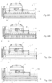
- At least three holes can be provided in each side in order to mount a support for the roller, a pin being engaged in a first hole in the side and in a corresponding first hole in the support, by means of which pin each support is hinged to the corresponding side, a screw alternatively being engaged in a second and third hole in the side and passing through a second hole in the support in order to fix the roller to the corresponding side in one position and in the other position, respectively, of said first and second positions.
- At least three holes can be provided in each side in order to mount a plate of the end element, a pin being engaged in a first hole in the side and in a corresponding first hole in a plate of said end element, by means of which pin each plate is hinged to the corresponding side, a screw alternatively being engaged in a second and third hole in the side and passing through a second hole in the plate of said end element in order to fix said end element to the corresponding side in one position and in the other position, respectively, of said first and second positions.
- a sequence of first holes can be made in each side, which holes are arranged along a curvilinear axis so as to be equidistant from the second or third hole in the side.
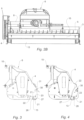
- the closure element 15 is a scraper with an adjustable doctor blade 16, which scraper is supported between the sides 3, 4 by means of the respective perforated plates 16a.
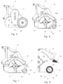
- the choking of the rear opening 20 is adjusted by positioning the closure element 15 and the end element 13, which are mounted for this purpose on the respective sides 3, 4 so as to be movable between a first position ( Figure 6 ), in which the end element 13 is further removed (moved back) with respect to the rotor 11 and the closure element 15 is oriented in a position close to the end element 13 so as to, at least in part, close the opening 20 in order to hold the cut material in the chamber for longer, and a second position ( Figure 8 ) in which the end element 13 is moved closer to the rotor 11 than in the first position and the closure element 15 is oriented in a position remote from the end element 13 so as to substantially free the opening 20 and facilitate discharging of the cut material from the cutting chamber.
- a passage 33 is defined between the roller and the scraper, which passage is preferably completely closed or left open in the case in which the roller and the scraper are in the first position ( Figure 6 ) or, respectively, in the second position ( Figure 8 ).
- the holes 30 may have an elongated shape, preferably with a curvilinear profile, so as to allow the orientation of the closure element 15 to be continuously adjusted with respect to the sides 3, 4.
- the machine according to the invention can comprise fastening means for fastening the closure element 15 to the sides 3, 4 so as to be able to adjust the position of the closure element 15 with respect to the sides 3, 4.
- a rod 31 of counter-blades 32 can be removably mounted between the sides 3, 4 close to the closure element 15, in particular to the scraper, in order to keep insufficiently cut organic remains in the cutting chamber 29 until they have been completely shredded.
Landscapes
- Life Sciences & Earth Sciences (AREA)
- Environmental Sciences (AREA)
- Soil Working Implements (AREA)
Claims (9)
- Schneidemaschine, umfassend:- einen Körper (2) mit zwei seitlichen, nebeneinander liegenden Seiten (3, 4) und einer zwischen den Seiten (3, 4) montierten Haube (5) zur Begrenzung einer Schneidkammer (29), wobei die Kammer (29) eine hintere Öffnung (20) zum Abführen des Schnittgutes aufweist,- einen Rotor (11), der in der Kammer (29) zwischen den Seiten (3, 4) drehbar gelagert ist,- ein Endelement (13), das zwischen den Seiten (3, 4) an der hinteren Öffnung (20) der Kammer (29) gelagert wird, und- ein Verschlusselement (15), das zwischen den Seiten (3, 4) gelagert ist, wobei das Verschlusselement (15) und das Endelement (13) an den Seiten (3, 4) montiert sind, um zwischen einer ersten Position, in der das Endelement (13) vom Rotor (11) zurückbewegt wird und das Verschlusselement (15) in einer Position nahe dem Endelement (13) ausgerichtet ist, um die Öffnung (20) zumindest teilweise zu verschließen, um das Schnittgut länger in der Kammer (29) zu halten, und einer zweiten Position beweglich zu sein, in der das Endelement (13) näher an den Rotor (11) bewegt wird als in der ersten Position, und das Verschlusselement (15) in einer vom Endelement (13) entfernten Position ausgerichtet ist, um die Öffnung im Wesentlichen freizugeben und das Abführen des Schnittguts aus der Kammer (29) zu ermöglichen, dadurch gekennzeichnet, dass das Endelement (13) entweder eine Nivellierwalze und das Verschlusselement (15) ein Abstreifer oder das Endelement (13) ein Verfeinerungsgitter oder ein Lamellenelement ohne Löcher ist.
- Schneidemaschine nach Anspruch 1, wobei zumindest drei Löcher (21, 22, 23) in jeder Seite (3, 4) vorgesehen sind, um eine Halterung (14) für die Walze (13) zu montieren, ein Stift (26) vorgesehen ist, der in ein erstes Loch in der Seite (21) und in ein entsprechendes erstes Loch (25) in der Halterung (14) eingreift, wobei mittels dieses Stifts jede Halterung (14) an der entsprechenden Seite (3, 4) angelenkt ist und eine Schraube (27) vorgesehen ist, die abwechselnd in ein zweites und drittes Loch (22, 23) in der Seite (3, 4) eingreift und durch ein zweites Loch (28) in der Halterung (14) hindurchgeht, um die Walze (13) an der entsprechenden Seite (3, 4) in einer Position bzw. in der anderen Position der ersten und zweiten Position zu fixieren.
- Schneidemaschine nach Anspruch 1, wobei das Endelement (13) ein Verfeinerungsgitter oder ein laminares Element ohne Löcher ist und wobei in jeder Seite (3, 4) zumindest drei Löcher (21, 22, 23) vorgesehen sind, um eine Platte des Endelements (13) zu montieren, ein Stift (26) vorgesehen ist, der in ein erstes Loch (21) in der Seite (3, 4) und in ein entsprechendes erstes Loch in einer Platte des Endelements (13) eingreift, wobei mittels dieses Stifts jede Platte an der entsprechenden Seite (3, 4) angelenkt ist, eine Schraube (27) vorgesehen ist, die abwechselnd in ein zweites und drittes Loch (22, 23) in der Seite (3, 4) eingreift und durch ein zweites Loch (28) in der Platte des Elements (13) hindurchgeht, um das Endelement an der entsprechenden Seite (3, 4) in einer Position bzw. in der anderen Position der ersten und zweiten Position zu fixieren.
- Schneidemaschine nach Anspruch 2 oder Anspruch 3, wobei eine Folge von ersten Löchern (21) in jeder Seite (3, 4) ausgebildet und entlang einer kurvenförmigen Achse angeordnet sind, um den gleichen Abstand vom zweiten oder dritten Loch (22, 23) in der Seite (3, 4) aufzuweisen.
- Schneidemaschine nach Anspruch 2 oder Anspruch 3, wobei das erste Loch (21) ein Paar von kurvenförmigen Segmenten aufweist, die ein im Wesentlichen V-förmiges Profil bilden.
- Schneidemaschine nach einem oder mehreren der vorhergehenden Ansprüche, wobei die Schneidemaschine Befestigungsmittel zum Befestigen des Verschlusselements (15) an den Seiten (3, 4) aufweist, um die Position des Verschlusselements (15) in Bezug auf die Seiten (3, 4) einstellen zu können.
- Schneidemaschine nach einem oder mehreren der vorhergehenden Ansprüche, wobei eine Mehrzahl von Löchern (30) in jeder Seite (3, 4) vorgesehen ist, um das Verschlusselement (15) in einer Position bzw. in der anderen Position der ersten und zweiten Position zu fixieren.
- Schneidemaschine nach einem oder mehreren der vorhergehenden Ansprüche, die eine Stange (31) mit Gegenmessern (32) aufweist, die zwischen den Seiten (3, 4) in der Nähe des Verschlusselements (15) abnehmbar montiert ist.
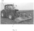
- Schneidmaschine nach einem oder mehreren der vorhergehenden Ansprüche, die einen Rahmen (6) aufweist, der zur Befestigung an drei Punkten (10) vorgesehen ist, um entweder an der Vorderseite oder an der Rückseite eines landwirtschaftlichen Traktors (100) montiert zu werden.
Applications Claiming Priority (2)
| Application Number | Priority Date | Filing Date | Title |
|---|---|---|---|
| IT102017000057717A IT201700057717A1 (it) | 2017-05-26 | 2017-05-26 | Macchina trinciatrice perfezionata |
| PCT/IB2018/053736 WO2018215983A1 (en) | 2017-05-26 | 2018-05-25 | Improved cutting machine |
Publications (3)
| Publication Number | Publication Date |
|---|---|
| EP3554215A1 EP3554215A1 (de) | 2019-10-23 |
| EP3554215C0 EP3554215C0 (de) | 2023-12-27 |
| EP3554215B1 true EP3554215B1 (de) | 2023-12-27 |
Family
ID=60138732
Family Applications (1)
| Application Number | Title | Priority Date | Filing Date |
|---|---|---|---|
| EP18732907.3A Active EP3554215B1 (de) | 2017-05-26 | 2018-05-25 | Verbesserte schneidmaschine |
Country Status (3)
| Country | Link |
|---|---|
| EP (1) | EP3554215B1 (de) |
| IT (1) | IT201700057717A1 (de) |
| WO (1) | WO2018215983A1 (de) |
Family Cites Families (4)
| Publication number | Priority date | Publication date | Assignee | Title |
|---|---|---|---|---|
| GB1574189A (en) * | 1977-11-29 | 1980-09-03 | Longman T | Lawn mower (rotary cylinder) deflector mulcher plate |
| ITBO20060483A1 (it) * | 2006-06-21 | 2007-12-22 | Nobili S P A | Apparecchiatura per la trinciatura di materiale. |
| IT1391061B1 (it) * | 2008-10-02 | 2011-11-18 | Nobili S P A | Apparecchiatura per la trinciatura di materiale. |
| ES2647877T3 (es) * | 2014-09-17 | 2017-12-27 | Müthing GmbH & Co. KG | Dispositivo de trabajo agrícola |
-
2017
- 2017-05-26 IT IT102017000057717A patent/IT201700057717A1/it unknown
-
2018
- 2018-05-25 WO PCT/IB2018/053736 patent/WO2018215983A1/en not_active Ceased
- 2018-05-25 EP EP18732907.3A patent/EP3554215B1/de active Active
Also Published As
| Publication number | Publication date |
|---|---|
| EP3554215A1 (de) | 2019-10-23 |
| WO2018215983A1 (en) | 2018-11-29 |
| IT201700057717A1 (it) | 2018-11-26 |
| EP3554215C0 (de) | 2023-12-27 |
Similar Documents
| Publication | Publication Date | Title |
|---|---|---|
| EP3272199A1 (de) | Mulchgerät zur bearbeitung von auf einem feld stehenden pflanzenstümpfen | |
| DE60313399T2 (de) | Zerkleinerungsvorrichtung für Stoppel und Mähdrescher mit solcher Vorrichtung | |
| DE202010006714U1 (de) | Feldhäcksler | |
| DE202014104668U1 (de) | Bodenbearbeitungsvorrichtung | |
| EP3469865B1 (de) | Mulchgerät mit schlegel- und sichelmähwerk | |
| US2656662A (en) | Tractor mounted stalk shredding device | |
| EP2792232B1 (de) | Aufnahmeeinrichtung für Häcksler für Schnittgut | |
| US2612017A (en) | Stalk shredder | |
| EP3554215B1 (de) | Verbesserte schneidmaschine | |
| EP0030568B1 (de) | Schneidwerk zum Beschneiden von Hecken und Büschen oder dergleichen | |
| KR101330017B1 (ko) | 배토두둑성형장치 | |
| SU1750482A1 (ru) | Молотильный аппарат | |
| EP1852011A1 (de) | Selbstfahrender Feldhäcksler | |
| DE102007050042B4 (de) | Häcksler und Aufnahmevorrichtung für Schnittgut | |
| DE2445702A1 (de) | Feldhaecksler mit haeckseltrommel | |
| WO2007125557A1 (en) | New knife/crushing unit for agricultural and industrial crushing machines | |
| EP2882274B1 (de) | Vorrichtung zum schneiden einer auf der erdoberfläche aufliegenden decke organischen materials und ihre verwendung | |
| EP3811759B1 (de) | Mulchgerät zur bearbeitung von auf einem feld stehenden pflanzenstoppeln mit pendelwinkelbegrenzung | |
| US3160214A (en) | Stalk and root lifting and shreding device | |
| CN105230247A (zh) | 一种秸秆粉碎还田抛撒机 | |
| WO2013111639A1 (ja) | コンバイン | |
| RU80092U1 (ru) | Косилка садовая | |
| IT201900009795A1 (it) | Trinciatrice per la lavorazione del terreno | |
| ITVI20080298A1 (it) | Macchina agricola perfezionata per il taglio e la frantumazione di materiali residui. | |
| DE60115984T2 (de) | Vegetation-Mähvorrichtung mit Schlegel-Häcksler und Schneideanordnung |
Legal Events
| Date | Code | Title | Description |
|---|---|---|---|
| STAA | Information on the status of an ep patent application or granted ep patent |
Free format text: STATUS: UNKNOWN |
|
| STAA | Information on the status of an ep patent application or granted ep patent |
Free format text: STATUS: THE INTERNATIONAL PUBLICATION HAS BEEN MADE |
|
| PUAI | Public reference made under article 153(3) epc to a published international application that has entered the european phase |
Free format text: ORIGINAL CODE: 0009012 |
|
| STAA | Information on the status of an ep patent application or granted ep patent |
Free format text: STATUS: REQUEST FOR EXAMINATION WAS MADE |
|
| 17P | Request for examination filed |
Effective date: 20190715 |
|
| AK | Designated contracting states |
Kind code of ref document: A1 Designated state(s): AL AT BE BG CH CY CZ DE DK EE ES FI FR GB GR HR HU IE IS IT LI LT LU LV MC MK MT NL NO PL PT RO RS SE SI SK SM TR |
|
| AX | Request for extension of the european patent |
Extension state: BA ME |
|
| DAV | Request for validation of the european patent (deleted) | ||
| DAX | Request for extension of the european patent (deleted) | ||
| STAA | Information on the status of an ep patent application or granted ep patent |
Free format text: STATUS: EXAMINATION IS IN PROGRESS |
|
| 17Q | First examination report despatched |
Effective date: 20211210 |
|
| GRAP | Despatch of communication of intention to grant a patent |
Free format text: ORIGINAL CODE: EPIDOSNIGR1 |
|
| STAA | Information on the status of an ep patent application or granted ep patent |
Free format text: STATUS: GRANT OF PATENT IS INTENDED |
|
| INTG | Intention to grant announced |
Effective date: 20230330 |
|
| GRAJ | Information related to disapproval of communication of intention to grant by the applicant or resumption of examination proceedings by the epo deleted |
Free format text: ORIGINAL CODE: EPIDOSDIGR1 |
|
| STAA | Information on the status of an ep patent application or granted ep patent |
Free format text: STATUS: EXAMINATION IS IN PROGRESS |
|
| INTC | Intention to grant announced (deleted) | ||
| GRAP | Despatch of communication of intention to grant a patent |
Free format text: ORIGINAL CODE: EPIDOSNIGR1 |
|
| STAA | Information on the status of an ep patent application or granted ep patent |
Free format text: STATUS: GRANT OF PATENT IS INTENDED |
|
| INTG | Intention to grant announced |
Effective date: 20230721 |
|
| GRAS | Grant fee paid |
Free format text: ORIGINAL CODE: EPIDOSNIGR3 |
|
| GRAA | (expected) grant |
Free format text: ORIGINAL CODE: 0009210 |
|
| STAA | Information on the status of an ep patent application or granted ep patent |
Free format text: STATUS: THE PATENT HAS BEEN GRANTED |
|
| AK | Designated contracting states |
Kind code of ref document: B1 Designated state(s): AL AT BE BG CH CY CZ DE DK EE ES FI FR GB GR HR HU IE IS IT LI LT LU LV MC MK MT NL NO PL PT RO RS SE SI SK SM TR |
|
| REG | Reference to a national code |
Ref country code: GB Ref legal event code: FG4D |
|
| REG | Reference to a national code |
Ref country code: CH Ref legal event code: EP |
|
| REG | Reference to a national code |
Ref country code: DE Ref legal event code: R096 Ref document number: 602018063193 Country of ref document: DE |
|
| REG | Reference to a national code |
Ref country code: IE Ref legal event code: FG4D |
|
| U01 | Request for unitary effect filed |
Effective date: 20240126 |
|
| U07 | Unitary effect registered |
Designated state(s): AT BE BG DE DK EE FI FR IT LT LU LV MT NL PT SE SI Effective date: 20240207 |
|
| PG25 | Lapsed in a contracting state [announced via postgrant information from national office to epo] |
Ref country code: GR Free format text: LAPSE BECAUSE OF FAILURE TO SUBMIT A TRANSLATION OF THE DESCRIPTION OR TO PAY THE FEE WITHIN THE PRESCRIBED TIME-LIMIT Effective date: 20240328 |
|
| PG25 | Lapsed in a contracting state [announced via postgrant information from national office to epo] |
Ref country code: ES Free format text: LAPSE BECAUSE OF FAILURE TO SUBMIT A TRANSLATION OF THE DESCRIPTION OR TO PAY THE FEE WITHIN THE PRESCRIBED TIME-LIMIT Effective date: 20231227 |
|
| PG25 | Lapsed in a contracting state [announced via postgrant information from national office to epo] |
Ref country code: GR Free format text: LAPSE BECAUSE OF FAILURE TO SUBMIT A TRANSLATION OF THE DESCRIPTION OR TO PAY THE FEE WITHIN THE PRESCRIBED TIME-LIMIT Effective date: 20240328 Ref country code: ES Free format text: LAPSE BECAUSE OF FAILURE TO SUBMIT A TRANSLATION OF THE DESCRIPTION OR TO PAY THE FEE WITHIN THE PRESCRIBED TIME-LIMIT Effective date: 20231227 |
|
| U20 | Renewal fee for the european patent with unitary effect paid |
Year of fee payment: 7 Effective date: 20240412 |
|
| PG25 | Lapsed in a contracting state [announced via postgrant information from national office to epo] |
Ref country code: RS Free format text: LAPSE BECAUSE OF FAILURE TO SUBMIT A TRANSLATION OF THE DESCRIPTION OR TO PAY THE FEE WITHIN THE PRESCRIBED TIME-LIMIT Effective date: 20231227 Ref country code: NO Free format text: LAPSE BECAUSE OF FAILURE TO SUBMIT A TRANSLATION OF THE DESCRIPTION OR TO PAY THE FEE WITHIN THE PRESCRIBED TIME-LIMIT Effective date: 20240327 Ref country code: HR Free format text: LAPSE BECAUSE OF FAILURE TO SUBMIT A TRANSLATION OF THE DESCRIPTION OR TO PAY THE FEE WITHIN THE PRESCRIBED TIME-LIMIT Effective date: 20231227 |
|
| PG25 | Lapsed in a contracting state [announced via postgrant information from national office to epo] |
Ref country code: IS Free format text: LAPSE BECAUSE OF FAILURE TO SUBMIT A TRANSLATION OF THE DESCRIPTION OR TO PAY THE FEE WITHIN THE PRESCRIBED TIME-LIMIT Effective date: 20240427 |
|
| PG25 | Lapsed in a contracting state [announced via postgrant information from national office to epo] |
Ref country code: CZ Free format text: LAPSE BECAUSE OF FAILURE TO SUBMIT A TRANSLATION OF THE DESCRIPTION OR TO PAY THE FEE WITHIN THE PRESCRIBED TIME-LIMIT Effective date: 20231227 |
|
| PG25 | Lapsed in a contracting state [announced via postgrant information from national office to epo] |
Ref country code: SK Free format text: LAPSE BECAUSE OF FAILURE TO SUBMIT A TRANSLATION OF THE DESCRIPTION OR TO PAY THE FEE WITHIN THE PRESCRIBED TIME-LIMIT Effective date: 20231227 |
|
| PG25 | Lapsed in a contracting state [announced via postgrant information from national office to epo] |
Ref country code: SM Free format text: LAPSE BECAUSE OF FAILURE TO SUBMIT A TRANSLATION OF THE DESCRIPTION OR TO PAY THE FEE WITHIN THE PRESCRIBED TIME-LIMIT Effective date: 20231227 Ref country code: SK Free format text: LAPSE BECAUSE OF FAILURE TO SUBMIT A TRANSLATION OF THE DESCRIPTION OR TO PAY THE FEE WITHIN THE PRESCRIBED TIME-LIMIT Effective date: 20231227 Ref country code: RO Free format text: LAPSE BECAUSE OF FAILURE TO SUBMIT A TRANSLATION OF THE DESCRIPTION OR TO PAY THE FEE WITHIN THE PRESCRIBED TIME-LIMIT Effective date: 20231227 Ref country code: IS Free format text: LAPSE BECAUSE OF FAILURE TO SUBMIT A TRANSLATION OF THE DESCRIPTION OR TO PAY THE FEE WITHIN THE PRESCRIBED TIME-LIMIT Effective date: 20240427 Ref country code: CZ Free format text: LAPSE BECAUSE OF FAILURE TO SUBMIT A TRANSLATION OF THE DESCRIPTION OR TO PAY THE FEE WITHIN THE PRESCRIBED TIME-LIMIT Effective date: 20231227 |
|
| PG25 | Lapsed in a contracting state [announced via postgrant information from national office to epo] |
Ref country code: PL Free format text: LAPSE BECAUSE OF FAILURE TO SUBMIT A TRANSLATION OF THE DESCRIPTION OR TO PAY THE FEE WITHIN THE PRESCRIBED TIME-LIMIT Effective date: 20231227 |
|
| PG25 | Lapsed in a contracting state [announced via postgrant information from national office to epo] |
Ref country code: PL Free format text: LAPSE BECAUSE OF FAILURE TO SUBMIT A TRANSLATION OF THE DESCRIPTION OR TO PAY THE FEE WITHIN THE PRESCRIBED TIME-LIMIT Effective date: 20231227 |
|
| REG | Reference to a national code |
Ref country code: DE Ref legal event code: R097 Ref document number: 602018063193 Country of ref document: DE |
|
| PLBE | No opposition filed within time limit |
Free format text: ORIGINAL CODE: 0009261 |
|
| STAA | Information on the status of an ep patent application or granted ep patent |
Free format text: STATUS: NO OPPOSITION FILED WITHIN TIME LIMIT |
|
| 26N | No opposition filed |
Effective date: 20240930 |
|
| REG | Reference to a national code |
Ref country code: CH Ref legal event code: PL |
|
| PG25 | Lapsed in a contracting state [announced via postgrant information from national office to epo] |
Ref country code: MC Free format text: LAPSE BECAUSE OF FAILURE TO SUBMIT A TRANSLATION OF THE DESCRIPTION OR TO PAY THE FEE WITHIN THE PRESCRIBED TIME-LIMIT Effective date: 20231227 |
|
| GBPC | Gb: european patent ceased through non-payment of renewal fee |
Effective date: 20240525 |
|
| PG25 | Lapsed in a contracting state [announced via postgrant information from national office to epo] |
Ref country code: MC Free format text: LAPSE BECAUSE OF FAILURE TO SUBMIT A TRANSLATION OF THE DESCRIPTION OR TO PAY THE FEE WITHIN THE PRESCRIBED TIME-LIMIT Effective date: 20231227 Ref country code: CH Free format text: LAPSE BECAUSE OF NON-PAYMENT OF DUE FEES Effective date: 20240531 |
|
| PG25 | Lapsed in a contracting state [announced via postgrant information from national office to epo] |
Ref country code: IE Free format text: LAPSE BECAUSE OF NON-PAYMENT OF DUE FEES Effective date: 20240525 |
|
| PG25 | Lapsed in a contracting state [announced via postgrant information from national office to epo] |
Ref country code: GB Free format text: LAPSE BECAUSE OF NON-PAYMENT OF DUE FEES Effective date: 20240525 |
|
| U20 | Renewal fee for the european patent with unitary effect paid |
Year of fee payment: 8 Effective date: 20250409 |
|
| PG25 | Lapsed in a contracting state [announced via postgrant information from national office to epo] |
Ref country code: HU Free format text: LAPSE BECAUSE OF FAILURE TO SUBMIT A TRANSLATION OF THE DESCRIPTION OR TO PAY THE FEE WITHIN THE PRESCRIBED TIME-LIMIT; INVALID AB INITIO Effective date: 20180525 |
|
| PG25 | Lapsed in a contracting state [announced via postgrant information from national office to epo] |
Ref country code: CY Free format text: LAPSE BECAUSE OF FAILURE TO SUBMIT A TRANSLATION OF THE DESCRIPTION OR TO PAY THE FEE WITHIN THE PRESCRIBED TIME-LIMIT; INVALID AB INITIO Effective date: 20180525 |