EP3554215B1 - Machine améliorée de coupe - Google Patents
Machine améliorée de coupe Download PDFInfo
- Publication number
- EP3554215B1 EP3554215B1 EP18732907.3A EP18732907A EP3554215B1 EP 3554215 B1 EP3554215 B1 EP 3554215B1 EP 18732907 A EP18732907 A EP 18732907A EP 3554215 B1 EP3554215 B1 EP 3554215B1
- Authority
- EP
- European Patent Office
- Prior art keywords
- cutting machine
- sides
- hole
- end element
- closure element
- Prior art date
- Legal status (The legal status is an assumption and is not a legal conclusion. Google has not performed a legal analysis and makes no representation as to the accuracy of the status listed.)
- Active
Links
Images

Classifications
-
- A—HUMAN NECESSITIES
- A01—AGRICULTURE; FORESTRY; ANIMAL HUSBANDRY; HUNTING; TRAPPING; FISHING
- A01D—HARVESTING; MOWING
- A01D34/00—Mowers; Mowing apparatus of harvesters
- A01D34/01—Mowers; Mowing apparatus of harvesters characterised by features relating to the type of cutting apparatus
- A01D34/412—Mowers; Mowing apparatus of harvesters characterised by features relating to the type of cutting apparatus having rotating cutters
- A01D34/42—Mowers; Mowing apparatus of harvesters characterised by features relating to the type of cutting apparatus having rotating cutters having cutters rotating about a horizontal axis, e.g. cutting-cylinders
- A01D34/62—Other details
Definitions
- Machines including said characteristics are known from the current production of the applicant themselves.
- EP 2997802 A1 An example of agricultural working device is disclosed in EP 2997802 A1 .
- these machines can be used for more or less heavy work, ranging from a simple lawn or straw cutting all the way to the cutting of stalks, shoots and wood.
- the machines can shred the material handled to a more or less fine degree.
- a cutting machine comprises:
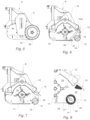
- At least three holes can be provided in each side in order to mount a support for the roller, a pin being engaged in a first hole in the side and in a corresponding first hole in the support, by means of which pin each support is hinged to the corresponding side, a screw alternatively being engaged in a second and third hole in the side and passing through a second hole in the support in order to fix the roller to the corresponding side in one position and in the other position, respectively, of said first and second positions.
- At least three holes can be provided in each side in order to mount a plate of the end element, a pin being engaged in a first hole in the side and in a corresponding first hole in a plate of said end element, by means of which pin each plate is hinged to the corresponding side, a screw alternatively being engaged in a second and third hole in the side and passing through a second hole in the plate of said end element in order to fix said end element to the corresponding side in one position and in the other position, respectively, of said first and second positions.
- a sequence of first holes can be made in each side, which holes are arranged along a curvilinear axis so as to be equidistant from the second or third hole in the side.
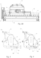
- the closure element 15 is a scraper with an adjustable doctor blade 16, which scraper is supported between the sides 3, 4 by means of the respective perforated plates 16a.
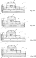
- the choking of the rear opening 20 is adjusted by positioning the closure element 15 and the end element 13, which are mounted for this purpose on the respective sides 3, 4 so as to be movable between a first position ( Figure 6 ), in which the end element 13 is further removed (moved back) with respect to the rotor 11 and the closure element 15 is oriented in a position close to the end element 13 so as to, at least in part, close the opening 20 in order to hold the cut material in the chamber for longer, and a second position ( Figure 8 ) in which the end element 13 is moved closer to the rotor 11 than in the first position and the closure element 15 is oriented in a position remote from the end element 13 so as to substantially free the opening 20 and facilitate discharging of the cut material from the cutting chamber.
- a passage 33 is defined between the roller and the scraper, which passage is preferably completely closed or left open in the case in which the roller and the scraper are in the first position ( Figure 6 ) or, respectively, in the second position ( Figure 8 ).
- the holes 30 may have an elongated shape, preferably with a curvilinear profile, so as to allow the orientation of the closure element 15 to be continuously adjusted with respect to the sides 3, 4.
- the machine according to the invention can comprise fastening means for fastening the closure element 15 to the sides 3, 4 so as to be able to adjust the position of the closure element 15 with respect to the sides 3, 4.
- a rod 31 of counter-blades 32 can be removably mounted between the sides 3, 4 close to the closure element 15, in particular to the scraper, in order to keep insufficiently cut organic remains in the cutting chamber 29 until they have been completely shredded.
Landscapes
- Life Sciences & Earth Sciences (AREA)
- Environmental Sciences (AREA)
- Soil Working Implements (AREA)
Claims (9)
- Machine de coupe comprenant :- un corps (2) présentant deux côtés (3, 4) juxtaposés latéraux et une hotte (5) montée entre lesdits côtés (3, 4) pour délimiter une chambre (29) de coupe, ladite chambre (29) présentant une ouverture (20) arrière pour évacuer le matériau découpé,- un rotor (11) qui est soutenu de manière rotative dans ladite chambre (29) entre lesdits côtés (3, 4),- un élément d'extrémité (13) soutenu entre lesdits côtés (3, 4) au niveau de ladite ouverture (20) arrière de ladite chambre (29), et- un élément de fermeture (15) soutenu entre lesdits côtés (3, 4), ledit élément de fermeture (15) et ledit élément d'extrémité (13) étant montés sur lesdits côtés (3, 4) de manière à être mobiles entre une première position, dans laquelle ledit élément d'extrémité (13) est déplacé en arrière depuis le rotor (11) et ledit élément de fermeture (15) est orienté dans une position proche de l'élément d'extrémité (13) de manière à fermer ladite ouverture (20), au moins en partie, pour maintenir le matériau découpé dans la chambre (29) plus longtemps, et une seconde position, dans laquelle ledit élément d'extrémité (13) est déplacé plus près du rotor (11) que dans la première position, et ledit élément de fermeture (15) est orienté dans une position éloignée dudit élément d'extrémité (13) de manière à libérer sensiblement ladite ouverture et à faciliter l'évacuation du matériau découpé de la chambre (29), caractérisée en ce que ledit élément d'extrémité (13) est un rouleau de nivellement et ledit élément de fermeture (15) est un racloir, ou ledit élément d'extrémité (13) est une grille d'affinage ou un élément laminaire dépourvu de tout trou.
- Machine de coupe selon la revendication 1, dans laquelle au moins trois trous (21, 22, 23) sont prévus dans chaque côté (3, 4) pour monter un support (14) pour ledit rouleau (13), une goupille (26) étant mise en prise dans un premier trou dans le côté (21) et un premier trou (25) correspondant dans le support (14), goupille au moyen de laquelle chaque support (14) est articulé au côté (3, 4) correspondant, une vis (27) étant mise en prise alternativement dans un deuxième et un troisième trou (22, 23) et passant à travers un second trou (28) dans le support (14) pour fixer le rouleau (13) au côté (3, 4) correspondant dans une position et dans l'autre position, respectivement, desdites première et seconde positions.
- Machine de coupe selon la revendication 1, dans laquelle ledit élément d'extrémité (13) est une grille d'affinage ou un élément laminaire dépourvu de tout trou, et dans laquelle au moins trois trous (21, 22, 23) sont prévus dans chaque côté (3, 4) pour monter une plaque dudit élément d'extrémité (13), une goupille (26) étant mise en prise dans un premier trou (21) dans le côté (3, 4) et dans un premier trou correspondant dans une plaque dudit élément d'extrémité (13), goupille au moyen de laquelle chaque plaque est articulée au côté (3, 4) correspondant, une vis (27) étant mise en prise alternativement dans un deuxième et un troisième trou (22, 23) dans le côté (3, 4) et passant à travers un second trou (28) dans la plaque dudit élément (13) pour fixer ledit élément d'extrémité au côté (3, 4) correspondant dans une position et dans l'autre position, respectivement, desdites première et seconde positions.
- Machine de coupe selon la revendication 2 ou la revendication 3, dans laquelle une séquence desdits premiers trous (21) est réalisée dans chaque côté (3, 4) et est agencée le long d'un axe curviligne de manière à être à égale distance du deuxième ou du troisième trou (22, 23) dans le côté (3, 4).
- Machine de coupe selon la revendication 2 ou la revendication 3, dans laquelle ledit premier trou (21) comprend une paire de segments curvilignes qui forment un profil sensiblement en forme de V.
- Machine de coupe selon l'une ou plusieurs des revendications précédentes, dans laquelle ladite machine de coupe comprend des moyens de fixation pour fixer ledit élément de fermeture (15) auxdits côtés (3, 4) de manière à pouvoir ajuster la position dudit élément de fermeture (15) par rapport auxdits côtés (3, 4).
- Machine de coupe selon l'une ou plusieurs des revendications précédentes, dans laquelle une pluralité de trous (30) sont prévus dans chaque côté (3, 4) pour fixer ledit élément de fermeture (15) dans une position et dans l'autre position, respectivement, desdites première et seconde positions.
- Machine de découpe selon l'une ou plusieurs des revendications précédentes, comprenant une tige (31) de contre-lames (32) qui est montée de manière amovible entre lesdits côtés (3, 4) à proximité dudit élément de fermeture (15).
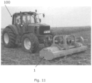
- Machine de coupe selon l'une ou plusieurs des revendications précédentes, comprenant un cadre (6) prévu pour une attache en trois points (10) pour être monté sur l'avant ou l'arrière d'un tracteur agricole (100).
Applications Claiming Priority (2)
| Application Number | Priority Date | Filing Date | Title |
|---|---|---|---|
| IT102017000057717A IT201700057717A1 (it) | 2017-05-26 | 2017-05-26 | Macchina trinciatrice perfezionata |
| PCT/IB2018/053736 WO2018215983A1 (fr) | 2017-05-26 | 2018-05-25 | Machine améliorée de coupe |
Publications (3)
| Publication Number | Publication Date |
|---|---|
| EP3554215A1 EP3554215A1 (fr) | 2019-10-23 |
| EP3554215B1 true EP3554215B1 (fr) | 2023-12-27 |
| EP3554215C0 EP3554215C0 (fr) | 2023-12-27 |
Family
ID=60138732
Family Applications (1)
| Application Number | Title | Priority Date | Filing Date |
|---|---|---|---|
| EP18732907.3A Active EP3554215B1 (fr) | 2017-05-26 | 2018-05-25 | Machine améliorée de coupe |
Country Status (3)
| Country | Link |
|---|---|
| EP (1) | EP3554215B1 (fr) |
| IT (1) | IT201700057717A1 (fr) |
| WO (1) | WO2018215983A1 (fr) |
Family Cites Families (4)
| Publication number | Priority date | Publication date | Assignee | Title |
|---|---|---|---|---|
| GB1574189A (en) * | 1977-11-29 | 1980-09-03 | Longman T | Lawn mower (rotary cylinder) deflector mulcher plate |
| ITBO20060483A1 (it) * | 2006-06-21 | 2007-12-22 | Nobili S P A | Apparecchiatura per la trinciatura di materiale. |
| IT1391061B1 (it) * | 2008-10-02 | 2011-11-18 | Nobili S P A | Apparecchiatura per la trinciatura di materiale. |
| SI2997802T1 (en) * | 2014-09-17 | 2018-01-31 | Muething Gmbh & Co. Kg | Agricultural working device |
-
2017
- 2017-05-26 IT IT102017000057717A patent/IT201700057717A1/it unknown
-
2018
- 2018-05-25 WO PCT/IB2018/053736 patent/WO2018215983A1/fr not_active Ceased
- 2018-05-25 EP EP18732907.3A patent/EP3554215B1/fr active Active
Also Published As
| Publication number | Publication date |
|---|---|
| WO2018215983A1 (fr) | 2018-11-29 |
| IT201700057717A1 (it) | 2018-11-26 |
| EP3554215A1 (fr) | 2019-10-23 |
| EP3554215C0 (fr) | 2023-12-27 |
Similar Documents
| Publication | Publication Date | Title |
|---|---|---|
| EP3272199A1 (fr) | Broyeur destiné au traitement de résidus de cultures dans un champ | |
| DE60313399T2 (de) | Zerkleinerungsvorrichtung für Stoppel und Mähdrescher mit solcher Vorrichtung | |
| DE202010006714U1 (de) | Feldhäcksler | |
| DE202014104668U1 (de) | Bodenbearbeitungsvorrichtung | |
| US2656662A (en) | Tractor mounted stalk shredding device | |
| EP2792232B1 (fr) | Dispositif de ramassage pour broyeur pour materiél à couper | |
| US2612017A (en) | Stalk shredder | |
| EP3554215B1 (fr) | Machine améliorée de coupe | |
| EP0030568B1 (fr) | Coupoir pour la taille d'haies et d'arbustes ou autres choses senblables | |
| DE19753486B4 (de) | Häckselvorrichtung | |
| EP3469865A1 (fr) | Appareil de paillage pourvu de faucheuse à fléaux et à lames | |
| KR101330017B1 (ko) | 배토두둑성형장치 | |
| SU1750482A1 (ru) | Молотильный аппарат | |
| EP1852011A1 (fr) | Ramasseuse-hacheuse automobile | |
| DE102007050042B4 (de) | Häcksler und Aufnahmevorrichtung für Schnittgut | |
| DE2445702A1 (de) | Feldhaecksler mit haeckseltrommel | |
| WO2007125557A1 (fr) | Nouvelle unite de couteau/broyage pour machines de broyage agricoles et industrielles | |
| EP2882274B1 (fr) | Dispositif pour entailler une couche de matière organique couchée sur la surface du sol, et utilisation de ce dispositif | |
| US3160214A (en) | Stalk and root lifting and shreding device | |
| CN105230247A (zh) | 一种秸秆粉碎还田抛撒机 | |
| WO2013111639A1 (fr) | Moissonneuse-batteuse | |
| RU80092U1 (ru) | Косилка садовая | |
| IT201900009795A1 (it) | Trinciatrice per la lavorazione del terreno | |
| ITVI20080298A1 (it) | Macchina agricola perfezionata per il taglio e la frantumazione di materiali residui. | |
| DE60115984T2 (de) | Vegetation-Mähvorrichtung mit Schlegel-Häcksler und Schneideanordnung |
Legal Events
| Date | Code | Title | Description |
|---|---|---|---|
| STAA | Information on the status of an ep patent application or granted ep patent |
Free format text: STATUS: UNKNOWN |
|
| STAA | Information on the status of an ep patent application or granted ep patent |
Free format text: STATUS: THE INTERNATIONAL PUBLICATION HAS BEEN MADE |
|
| PUAI | Public reference made under article 153(3) epc to a published international application that has entered the european phase |
Free format text: ORIGINAL CODE: 0009012 |
|
| STAA | Information on the status of an ep patent application or granted ep patent |
Free format text: STATUS: REQUEST FOR EXAMINATION WAS MADE |
|
| 17P | Request for examination filed |
Effective date: 20190715 |
|
| AK | Designated contracting states |
Kind code of ref document: A1 Designated state(s): AL AT BE BG CH CY CZ DE DK EE ES FI FR GB GR HR HU IE IS IT LI LT LU LV MC MK MT NL NO PL PT RO RS SE SI SK SM TR |
|
| AX | Request for extension of the european patent |
Extension state: BA ME |
|
| DAV | Request for validation of the european patent (deleted) | ||
| DAX | Request for extension of the european patent (deleted) | ||
| STAA | Information on the status of an ep patent application or granted ep patent |
Free format text: STATUS: EXAMINATION IS IN PROGRESS |
|
| 17Q | First examination report despatched |
Effective date: 20211210 |
|
| GRAP | Despatch of communication of intention to grant a patent |
Free format text: ORIGINAL CODE: EPIDOSNIGR1 |
|
| STAA | Information on the status of an ep patent application or granted ep patent |
Free format text: STATUS: GRANT OF PATENT IS INTENDED |
|
| INTG | Intention to grant announced |
Effective date: 20230330 |
|
| GRAJ | Information related to disapproval of communication of intention to grant by the applicant or resumption of examination proceedings by the epo deleted |
Free format text: ORIGINAL CODE: EPIDOSDIGR1 |
|
| STAA | Information on the status of an ep patent application or granted ep patent |
Free format text: STATUS: EXAMINATION IS IN PROGRESS |
|
| INTC | Intention to grant announced (deleted) | ||
| GRAP | Despatch of communication of intention to grant a patent |
Free format text: ORIGINAL CODE: EPIDOSNIGR1 |
|
| STAA | Information on the status of an ep patent application or granted ep patent |
Free format text: STATUS: GRANT OF PATENT IS INTENDED |
|
| INTG | Intention to grant announced |
Effective date: 20230721 |
|
| GRAS | Grant fee paid |
Free format text: ORIGINAL CODE: EPIDOSNIGR3 |
|
| GRAA | (expected) grant |
Free format text: ORIGINAL CODE: 0009210 |
|
| STAA | Information on the status of an ep patent application or granted ep patent |
Free format text: STATUS: THE PATENT HAS BEEN GRANTED |
|
| AK | Designated contracting states |
Kind code of ref document: B1 Designated state(s): AL AT BE BG CH CY CZ DE DK EE ES FI FR GB GR HR HU IE IS IT LI LT LU LV MC MK MT NL NO PL PT RO RS SE SI SK SM TR |
|
| REG | Reference to a national code |
Ref country code: GB Ref legal event code: FG4D |
|
| REG | Reference to a national code |
Ref country code: CH Ref legal event code: EP |
|
| REG | Reference to a national code |
Ref country code: DE Ref legal event code: R096 Ref document number: 602018063193 Country of ref document: DE |
|
| REG | Reference to a national code |
Ref country code: IE Ref legal event code: FG4D |
|
| U01 | Request for unitary effect filed |
Effective date: 20240126 |
|
| U07 | Unitary effect registered |
Designated state(s): AT BE BG DE DK EE FI FR IT LT LU LV MT NL PT SE SI Effective date: 20240207 |
|
| PG25 | Lapsed in a contracting state [announced via postgrant information from national office to epo] |
Ref country code: GR Free format text: LAPSE BECAUSE OF FAILURE TO SUBMIT A TRANSLATION OF THE DESCRIPTION OR TO PAY THE FEE WITHIN THE PRESCRIBED TIME-LIMIT Effective date: 20240328 |
|
| PG25 | Lapsed in a contracting state [announced via postgrant information from national office to epo] |
Ref country code: ES Free format text: LAPSE BECAUSE OF FAILURE TO SUBMIT A TRANSLATION OF THE DESCRIPTION OR TO PAY THE FEE WITHIN THE PRESCRIBED TIME-LIMIT Effective date: 20231227 |
|
| PG25 | Lapsed in a contracting state [announced via postgrant information from national office to epo] |
Ref country code: GR Free format text: LAPSE BECAUSE OF FAILURE TO SUBMIT A TRANSLATION OF THE DESCRIPTION OR TO PAY THE FEE WITHIN THE PRESCRIBED TIME-LIMIT Effective date: 20240328 Ref country code: ES Free format text: LAPSE BECAUSE OF FAILURE TO SUBMIT A TRANSLATION OF THE DESCRIPTION OR TO PAY THE FEE WITHIN THE PRESCRIBED TIME-LIMIT Effective date: 20231227 |
|
| U20 | Renewal fee for the european patent with unitary effect paid |
Year of fee payment: 7 Effective date: 20240412 |
|
| PG25 | Lapsed in a contracting state [announced via postgrant information from national office to epo] |
Ref country code: RS Free format text: LAPSE BECAUSE OF FAILURE TO SUBMIT A TRANSLATION OF THE DESCRIPTION OR TO PAY THE FEE WITHIN THE PRESCRIBED TIME-LIMIT Effective date: 20231227 Ref country code: NO Free format text: LAPSE BECAUSE OF FAILURE TO SUBMIT A TRANSLATION OF THE DESCRIPTION OR TO PAY THE FEE WITHIN THE PRESCRIBED TIME-LIMIT Effective date: 20240327 Ref country code: HR Free format text: LAPSE BECAUSE OF FAILURE TO SUBMIT A TRANSLATION OF THE DESCRIPTION OR TO PAY THE FEE WITHIN THE PRESCRIBED TIME-LIMIT Effective date: 20231227 |
|
| PG25 | Lapsed in a contracting state [announced via postgrant information from national office to epo] |
Ref country code: IS Free format text: LAPSE BECAUSE OF FAILURE TO SUBMIT A TRANSLATION OF THE DESCRIPTION OR TO PAY THE FEE WITHIN THE PRESCRIBED TIME-LIMIT Effective date: 20240427 |
|
| PG25 | Lapsed in a contracting state [announced via postgrant information from national office to epo] |
Ref country code: CZ Free format text: LAPSE BECAUSE OF FAILURE TO SUBMIT A TRANSLATION OF THE DESCRIPTION OR TO PAY THE FEE WITHIN THE PRESCRIBED TIME-LIMIT Effective date: 20231227 |
|
| PG25 | Lapsed in a contracting state [announced via postgrant information from national office to epo] |
Ref country code: SK Free format text: LAPSE BECAUSE OF FAILURE TO SUBMIT A TRANSLATION OF THE DESCRIPTION OR TO PAY THE FEE WITHIN THE PRESCRIBED TIME-LIMIT Effective date: 20231227 |
|
| PG25 | Lapsed in a contracting state [announced via postgrant information from national office to epo] |
Ref country code: SM Free format text: LAPSE BECAUSE OF FAILURE TO SUBMIT A TRANSLATION OF THE DESCRIPTION OR TO PAY THE FEE WITHIN THE PRESCRIBED TIME-LIMIT Effective date: 20231227 Ref country code: SK Free format text: LAPSE BECAUSE OF FAILURE TO SUBMIT A TRANSLATION OF THE DESCRIPTION OR TO PAY THE FEE WITHIN THE PRESCRIBED TIME-LIMIT Effective date: 20231227 Ref country code: RO Free format text: LAPSE BECAUSE OF FAILURE TO SUBMIT A TRANSLATION OF THE DESCRIPTION OR TO PAY THE FEE WITHIN THE PRESCRIBED TIME-LIMIT Effective date: 20231227 Ref country code: IS Free format text: LAPSE BECAUSE OF FAILURE TO SUBMIT A TRANSLATION OF THE DESCRIPTION OR TO PAY THE FEE WITHIN THE PRESCRIBED TIME-LIMIT Effective date: 20240427 Ref country code: CZ Free format text: LAPSE BECAUSE OF FAILURE TO SUBMIT A TRANSLATION OF THE DESCRIPTION OR TO PAY THE FEE WITHIN THE PRESCRIBED TIME-LIMIT Effective date: 20231227 |
|
| PG25 | Lapsed in a contracting state [announced via postgrant information from national office to epo] |
Ref country code: PL Free format text: LAPSE BECAUSE OF FAILURE TO SUBMIT A TRANSLATION OF THE DESCRIPTION OR TO PAY THE FEE WITHIN THE PRESCRIBED TIME-LIMIT Effective date: 20231227 |
|
| PG25 | Lapsed in a contracting state [announced via postgrant information from national office to epo] |
Ref country code: PL Free format text: LAPSE BECAUSE OF FAILURE TO SUBMIT A TRANSLATION OF THE DESCRIPTION OR TO PAY THE FEE WITHIN THE PRESCRIBED TIME-LIMIT Effective date: 20231227 |
|
| REG | Reference to a national code |
Ref country code: DE Ref legal event code: R097 Ref document number: 602018063193 Country of ref document: DE |
|
| PLBE | No opposition filed within time limit |
Free format text: ORIGINAL CODE: 0009261 |
|
| STAA | Information on the status of an ep patent application or granted ep patent |
Free format text: STATUS: NO OPPOSITION FILED WITHIN TIME LIMIT |
|
| 26N | No opposition filed |
Effective date: 20240930 |
|
| REG | Reference to a national code |
Ref country code: CH Ref legal event code: PL |
|
| PG25 | Lapsed in a contracting state [announced via postgrant information from national office to epo] |
Ref country code: MC Free format text: LAPSE BECAUSE OF FAILURE TO SUBMIT A TRANSLATION OF THE DESCRIPTION OR TO PAY THE FEE WITHIN THE PRESCRIBED TIME-LIMIT Effective date: 20231227 |
|
| GBPC | Gb: european patent ceased through non-payment of renewal fee |
Effective date: 20240525 |
|
| PG25 | Lapsed in a contracting state [announced via postgrant information from national office to epo] |
Ref country code: MC Free format text: LAPSE BECAUSE OF FAILURE TO SUBMIT A TRANSLATION OF THE DESCRIPTION OR TO PAY THE FEE WITHIN THE PRESCRIBED TIME-LIMIT Effective date: 20231227 Ref country code: CH Free format text: LAPSE BECAUSE OF NON-PAYMENT OF DUE FEES Effective date: 20240531 |
|
| PG25 | Lapsed in a contracting state [announced via postgrant information from national office to epo] |
Ref country code: IE Free format text: LAPSE BECAUSE OF NON-PAYMENT OF DUE FEES Effective date: 20240525 |
|
| PG25 | Lapsed in a contracting state [announced via postgrant information from national office to epo] |
Ref country code: GB Free format text: LAPSE BECAUSE OF NON-PAYMENT OF DUE FEES Effective date: 20240525 |
|
| U20 | Renewal fee for the european patent with unitary effect paid |
Year of fee payment: 8 Effective date: 20250409 |
|
| PG25 | Lapsed in a contracting state [announced via postgrant information from national office to epo] |
Ref country code: HU Free format text: LAPSE BECAUSE OF FAILURE TO SUBMIT A TRANSLATION OF THE DESCRIPTION OR TO PAY THE FEE WITHIN THE PRESCRIBED TIME-LIMIT; INVALID AB INITIO Effective date: 20180525 |
|
| PG25 | Lapsed in a contracting state [announced via postgrant information from national office to epo] |
Ref country code: CY Free format text: LAPSE BECAUSE OF FAILURE TO SUBMIT A TRANSLATION OF THE DESCRIPTION OR TO PAY THE FEE WITHIN THE PRESCRIBED TIME-LIMIT; INVALID AB INITIO Effective date: 20180525 |