EP3553791A1 - Installation de préhension et de découpe - Google Patents
Installation de préhension et de découpe Download PDFInfo
- Publication number
- EP3553791A1 EP3553791A1 EP19163873.3A EP19163873A EP3553791A1 EP 3553791 A1 EP3553791 A1 EP 3553791A1 EP 19163873 A EP19163873 A EP 19163873A EP 3553791 A1 EP3553791 A1 EP 3553791A1
- Authority
- EP
- European Patent Office
- Prior art keywords
- tilting
- rotating unit
- sawing
- barrel
- opening
- Prior art date
- Legal status (The legal status is an assumption and is not a legal conclusion. Google has not performed a legal analysis and makes no representation as to the accuracy of the status listed.)
- Granted
Links
Images

Classifications
-
- G—PHYSICS
- G21—NUCLEAR PHYSICS; NUCLEAR ENGINEERING
- G21D—NUCLEAR POWER PLANT
- G21D1/00—Details of nuclear power plant
- G21D1/003—Nuclear facilities decommissioning arrangements
-
- B—PERFORMING OPERATIONS; TRANSPORTING
- B23—MACHINE TOOLS; METAL-WORKING NOT OTHERWISE PROVIDED FOR
- B23D—PLANING; SLOTTING; SHEARING; BROACHING; SAWING; FILING; SCRAPING; LIKE OPERATIONS FOR WORKING METAL BY REMOVING MATERIAL, NOT OTHERWISE PROVIDED FOR
- B23D45/00—Sawing machines or sawing devices with circular saw blades or with friction saw discs
- B23D45/12—Sawing machines or sawing devices with circular saw blades or with friction saw discs with a circular saw blade for cutting tubes
- B23D45/124—Sawing machines or sawing devices with circular saw blades or with friction saw discs with a circular saw blade for cutting tubes the workpieces turning about their longitudinal axis during the cutting operations
-
- B—PERFORMING OPERATIONS; TRANSPORTING
- B28—WORKING CEMENT, CLAY, OR STONE
- B28D—WORKING STONE OR STONE-LIKE MATERIALS
- B28D1/00—Working stone or stone-like materials, e.g. brick, concrete or glass, not provided for elsewhere; Machines, devices, tools therefor
- B28D1/02—Working stone or stone-like materials, e.g. brick, concrete or glass, not provided for elsewhere; Machines, devices, tools therefor by sawing
- B28D1/04—Working stone or stone-like materials, e.g. brick, concrete or glass, not provided for elsewhere; Machines, devices, tools therefor by sawing with circular or cylindrical saw-blades or saw-discs
- B28D1/044—Working stone or stone-like materials, e.g. brick, concrete or glass, not provided for elsewhere; Machines, devices, tools therefor by sawing with circular or cylindrical saw-blades or saw-discs the saw blade being movable on slide ways
-
- G—PHYSICS
- G21—NUCLEAR PHYSICS; NUCLEAR ENGINEERING
- G21F—PROTECTION AGAINST X-RADIATION, GAMMA RADIATION, CORPUSCULAR RADIATION OR PARTICLE BOMBARDMENT; TREATING RADIOACTIVELY CONTAMINATED MATERIAL; DECONTAMINATION ARRANGEMENTS THEREFOR
- G21F5/00—Transportable or portable shielded containers
- G21F5/005—Containers for solid radioactive wastes, e.g. for ultimate disposal
-
- G—PHYSICS
- G21—NUCLEAR PHYSICS; NUCLEAR ENGINEERING
- G21F—PROTECTION AGAINST X-RADIATION, GAMMA RADIATION, CORPUSCULAR RADIATION OR PARTICLE BOMBARDMENT; TREATING RADIOACTIVELY CONTAMINATED MATERIAL; DECONTAMINATION ARRANGEMENTS THEREFOR
- G21F5/00—Transportable or portable shielded containers
- G21F5/06—Details of, or accessories to, the containers
- G21F5/14—Devices for handling containers or shipping-casks, e.g. transporting devices loading and unloading, filling of containers
-
- G—PHYSICS
- G21—NUCLEAR PHYSICS; NUCLEAR ENGINEERING
- G21F—PROTECTION AGAINST X-RADIATION, GAMMA RADIATION, CORPUSCULAR RADIATION OR PARTICLE BOMBARDMENT; TREATING RADIOACTIVELY CONTAMINATED MATERIAL; DECONTAMINATION ARRANGEMENTS THEREFOR
- G21F9/00—Treating radioactively contaminated material; Decontamination arrangements therefor
- G21F9/28—Treating solids
- G21F9/30—Processing
- G21F9/301—Processing by fixation in stable solid media
- G21F9/302—Processing by fixation in stable solid media in an inorganic matrix
- G21F9/304—Cement or cement-like matrix
-
- G—PHYSICS
- G21—NUCLEAR PHYSICS; NUCLEAR ENGINEERING
- G21F—PROTECTION AGAINST X-RADIATION, GAMMA RADIATION, CORPUSCULAR RADIATION OR PARTICLE BOMBARDMENT; TREATING RADIOACTIVELY CONTAMINATED MATERIAL; DECONTAMINATION ARRANGEMENTS THEREFOR
- G21F9/00—Treating radioactively contaminated material; Decontamination arrangements therefor
- G21F9/28—Treating solids
- G21F9/34—Disposal of solid waste
- G21F9/36—Disposal of solid waste by packaging; by baling
-
- Y—GENERAL TAGGING OF NEW TECHNOLOGICAL DEVELOPMENTS; GENERAL TAGGING OF CROSS-SECTIONAL TECHNOLOGIES SPANNING OVER SEVERAL SECTIONS OF THE IPC; TECHNICAL SUBJECTS COVERED BY FORMER USPC CROSS-REFERENCE ART COLLECTIONS [XRACs] AND DIGESTS
- Y02—TECHNOLOGIES OR APPLICATIONS FOR MITIGATION OR ADAPTATION AGAINST CLIMATE CHANGE
- Y02E—REDUCTION OF GREENHOUSE GAS [GHG] EMISSIONS, RELATED TO ENERGY GENERATION, TRANSMISSION OR DISTRIBUTION
- Y02E30/00—Energy generation of nuclear origin
Definitions
- the invention relates to a device for stripping, opening or trimming steel-coated barrels with concreted radioactive contents, according to the preamble of claim 1.
- radioactive waste has been collected, treated and stored.
- the aim of the measures is the chemical stabilization and safe inclusion of radionuclides in the forms of waste, and to achieve the lowest possible waste volume, since the intermediate and final disposal is associated with considerable costs.
- homogeneous cementation solid and liquid wastes are mixed with cement, water and possibly aggregates such as crushed stone or concrete liquefier.
- the waste form results in a concrete block in which the radionuclides are evenly distributed.
- This concrete block is usually located in a steel sheet barrel, usually with 200 l volume.
- the mixing process can be carried out either directly in this barrel with an infusion mixer, or in a separate mixing apparatus, before the still liquid concrete mixture is filled into the barrels.
- the resulting barrels are referred to below as homogeneous barrels.
- inhomogeneous cementation waste is usually filled loosely into 100 l drums. These barrels are closed with a lid, placed in a 200 l drum and the space filled with concrete. This procedure was chosen in the past because of the lack of conditioning facilities for flammable and liquid radioactive waste, but from today's perspective would no longer be able to be approved.
- the resulting barrels are also referred to below as inhomogeneous barrels. Both in homogeneous and inhomogeneous barrels These are steel-jacketed barrels with radioactive contents.
- post-conditioning and reconditioning In order to be able to guarantee long-term stable intermediate storage, suitable additional measures (“post-conditioning and reconditioning”) must therefore be taken.
- post-conditioning and reconditioning it has been proposed for aftertreatment of homogeneously cemented waste packages to adjust the container into suitable over drums, it being possible for the water contained beforehand to be removed by a drying process in order to reduce the reaction and corrosion potential.
- Modern drums for conditioned waste have a full-surface glued inner liner made of glass fiber reinforced plastic with sufficient thickness. This ensures that the interior paint is not damaged during loading.
- care must be taken with regard to transhipment that initially a sufficiently thick, pre-compacted, dry sand layer is introduced into the drum base before the 200 l drum can be adjusted. Subsequently, the cavity must be filled with sand and compacted. This procedure must be repeated until the drum is full. Only then can a reasonably secure positioning of the inner barrel be achieved in order to avoid damage to the overhang.
- a disadvantage with regard to the repository volume is that the overflow concept results in a volume increase of around 40%, which correspondingly increases the storage costs.
- the drying of large-volume concrete bodies is a very complex process. In the usually applied heating from the outside, for example in circulating air drying chambers, long drying times, since the concrete has a low thermal conductivity, which is further reduced by the progressing from outside to inside drying process. A uniform heating from the outside can basically also be done with microwaves. However, the resulting water vapor experiences a high diffusion resistance, so that it comes to a pressure build-up inside the body and ultimately to the bursting of the concrete blocks.
- the steel-clad concrete core is "over-drilled" by means of a diamond drill bit, that is made a hole in an axial feed movement between the outer steel shell and the concrete core.
- the reduced-diameter concrete core can be subsequently introduced into a new barrel.
- care must be taken to add water when working with diamond core drilling systems. Approx. 200 l of water must be supplied per drilling operation.
- excessive play in the slide guides also causes the diamond drill bit to "bleed” again and again.
- loose parts in the concrete, such as cut reinforcing bars or aggregates also lead to jamming of the drill bit.
- the removal of jammed diamond core bits is only possible with a great deal of time and personnel.
- Claim 1 relates to a device for stripping, opening or trimming Stahlummantelter barrels with concreted radioactive content, is proposed in the present invention that a processing chamber is provided with a takeover opening for the barrels, and arranged in the processing chamber tilting and rotation unit for receiving of the drums, wherein a drum with its longitudinal axis parallel to a longitudinal extension of the tilting and rotating unit is rotatable about the tilting and rotating unit about its longitudinal axis, and the tilting and rotating unit from an upright position with a substantially vertical longitudinal extent of the tilting and rotary unit in a horizontal position with a substantially horizontal longitudinal extension of the tilting and rotating unit is tilted, and at least two sawing or milling tools are provided, wherein at least one sawing or milling tool for stripping, opening or trimming the barrel in upright Position of the tilting and rotating unit is guided in its feed movement transverse to the longitudinal extension of the tilting and rotating unit, and at least one sawing or milling tool for stripping, opening or
- the processing of the barrels takes place on the one hand with a transverse to the longitudinal extent of the tilting and rotating unit guided feed movement of the saw or milling tool in the upright position of the tilting and rotating unit, as well as with a along the longitudinal extension of the tilting and rotating unit guided feed movement of the sawing or milling tool in horizontal position of the tilting and rotating unit.
- the processing of the barrels takes place from the outside, whereby sawing or milling tools can be used, which require no water cooling.
- the processing concept according to the invention allows a dry decomposition of the barrels, which was previously considered impossible.
- inhomogeneous barrels can in upright position of the tilting and rotating unit, which corresponds to a standing position of the barrel, after manual removal of the outer drum cover and thus exposure of the concrete core with a guided transversely to the longitudinal extent of the tilt and rotation unit feed movement of the saw or milling tool Barrel be capped in the lid area to open in this way, the inner barrel.
- This feed motion is also referred to below as a radial section, even if the feed motion does not have to be exactly radial.
- the separated lid area can be lifted off with lifting equipment when the barrel is in the upright position. Subsequently, the now open barrel can be tilted by means of the tilt and turn unit in a horizontal position to assess the radioactive content and to be able to clear.
- the wastes can be removed and treated according to current requirements, such as the incineration of combustible waste, the chemical-physical treatment of aqueous liquids, or the compacting of solid, incombustible waste.
- the concrete shell can be checked for contamination and cut into transportable or storable parts.
- the disassembled parts of the barrel are treated according to their nature, such as remelting of the steel sheets.
- the breaking up of the Sheath parts in sheath segments takes place at a lying position of the tilting and rotating unit, which corresponds to a lying position of the barrel, with the inventively along the longitudinal extent of the tilting and rotating unit guided feed movement of the sawing or milling tool.
- This feed motion is also referred to below as axial section, even if the feed motion does not have to be exactly axial.
- the steel casing of the drum can be cut in the bottom area.
- the barrel can be tilted by means of the tilt and turn unit in a horizontal position.
- the lying position of the tilting and rotating unit which corresponds to a lying position of the barrel, can be cut by axial cuts according to the invention along the longitudinal extension of the tilting and rotating unit guided feed movement of the saw or milling tool.
- the previously set radial cut in the floor area produces sheath segments which can easily be removed manually.
- the cutting of the steel shell and the milling of the concrete core in each lying position of the barrel could be done with the same sawing or Fräswerkmaschinehalter after exchange of the sawing tool against a milling tool.
- two rotating saw or Milling tools for stripping, opening or trimming the barrel are provided in horizontal position of the tilting and rotating unit, which are each movable along the longitudinal extent of the tilting and rotating unit, which is a guided along the longitudinal extent of the tilting and rotating unit sawing tool with horizontal Rotation level and a milling tool with vertical rotation plane is.
- the sawing tool and the milling tool are arranged on opposite sides of the tilting and rotating unit, wherein the sawing tool sets axial cuts and thus severed the drum casing in the axial direction, and the milling cutter mills the concrete core from the outside in inhomogeneous barrels.
- These operations are supported by the tilting and rotating unit by rotating the barrel about its longitudinal axis by an angle of, for example 120 ° when separating the shell after setting an axial section, in order to then set a new axial section.
- the drum can be rotated about its longitudinal axis with the aid of the tilt and turn unit to aid in the milling process.
- a rotating sawing tool which is guided transversely to the longitudinal extent of the tilting and rotating unit, be provided for stripping, opening or trimming the drum in an upright position of the tilting and rotating unit with a horizontal plane of rotation.
- This sawing tool performs the inventively provided feed movement transversely to the longitudinal extension of the tilting and rotating unit, which is also referred to as a radial section, such as in inhomogeneous barrels to cap the barrel in the lid area, or cut in homogeneous barrels the steel shell of the barrel in the bottom area.
- the sawing or milling tools are each mounted on a horizontally movable carriage.
- This storage is used in the intended for the processing of the barrels in their lying position sawing or milling tools to guide the feed movement of the sawing or milling tools along the longitudinal extent of the tilting and rotating unit.
- the carriage is guided in each case on a rail, which is next to the tilting or rotating unit in its lying position extends horizontally.
- the horizontal carriage serves to move the sawing tool from a lateral parking position into a machining position arranged centrally in the rail.
- This carriage is guided approximately on a rail which extends in the region of the take-over opening horizontally, but at right angles to the two above-mentioned rails.
- the sawing or milling tools are preferably rotary sawing or milling tools which are each guided by a pivoting arm with a pivot axis perpendicular to the plane of rotation of the respective sawing or milling tool.
- a pivoting arm with a pivot axis perpendicular to the plane of rotation of the respective sawing or milling tool At a first end of the swivel arm is articulated in each case on the above carriage, and at the opposite, free end of the swivel arm, the sawing or milling tool is attached.
- the sawing tools with a horizontal plane of rotation are thus each pivotable about a vertical pivot axis, and the milling tool with a vertical plane of rotation is pivotable about a horizontal pivot axis, wherein the pivot arm is preferably each pivotable through 360 °.
- About the swing arm of the contact pressure of the sawing or milling tool is ensured, so the penetrating in the radial direction in the barrel movement of the sawing or milling tools.
- the at least one sawing or milling tool is mounted on a vertically movable carriage.
- this vertically movable mounting of the sawing tool is advantageous, since this sawing or milling tool must cut the barrel in the lid area in the case of inhomogeneous barrels and in the case of homogeneous barrels Steel barrel of the barrel must cut in the bottom area, and thus a processing of the barrel is required at different heights.
- the vertical mobility can also be used to trim the barrel in height.
- this is vertical movable storage advantageous to edit, for example, barrels of different diameters.
- the processing chamber is provided with a closable roof opening.
- This roof opening is used, for example, in the processing of inhomogeneous barrels to lift the separated lid area in the standing position of the barrel or separated concrete parts in a horizontal position of the barrel by means of lifting devices from the processing chamber.
- the closable roof opening can be designed as a wing or sliding deck.
- the rotating sawing or milling tools are provided in their peripheral area with a dust extraction.
- This dust extraction system includes protective hoods for the sawing or milling tools, as well as an extraction system, so that sawdust or milling dust can be extracted via a cyclone pre-separator into a filter system.
- the tilting and rotating unit preferably provides that the tilting and rotating unit has a receptacle with a concave receiving surface, which partially surrounds the casing of a receptacle, the receptacle being provided with rotating rollers projecting beyond the receptacle surface.
- the recorded drum abuts the rotary rollers and is rotated by them about its longitudinal axis.
- the barrel is resting on a turntable of the tilting and rotating unit, bearing rollers may be provided to facilitate the rotational movement.
- the rotary rollers can be designed so that the barrel in a standing position during the rotational movement exerts a moment in the direction of the turntable.
- the tilting and rotating unit is slightly tilted in its upright position from the vertical, so that the barrel rests with a portion of its own weight on the rotating rollers and thus increases the frictional engagement. In the horizontal position of the barrel, the barrel rests anyway with its entire weight on the rotating rollers, which ensures a sufficient frictional engagement.
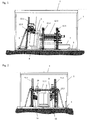
- Fig. 1 to 4 showing an embodiment of the device according to the invention, wherein the Fig. 1 and 2 the side walls 1 and the roof 2 of the processing chamber show, and in the 3 and 4 the side walls 1 and the roof 2 have been omitted.
- the device is constructed on a bottom plate 3 designed as a sealed stainless steel tub.
- the processing chamber is soundproof and equipped with two swing gates on the front and back, of which a swing gate forms a takeover opening for transporting the barrels 6 into the processing chamber, and the second swing gate allows the removal of the radioactive contents inhomogeneous barrels 6.
- the processing chamber is loaded on the side of the takeover opening, wherein transport carts 4 may be provided to move the barrel 6 at a suitable height to the tilting and rotating unit 5.
- the processing chamber is provided with a closable roof opening, which may be designed, for example, as a wing cover or sliding cover in order to remove concrete parts with a lifting device such as a crane and the like from the processing chamber.
- a mobile collection cup 7 made of stainless steel is visible in order to be able to transport away the contents of the inhomogeneous barrels.
- This collecting cup 7 is designed so that it can be pushed under the tilting and rotating unit 5 in order to avoid a contamination carryover.
- the tilting and rotating unit 5 has a jacket of a recorded drum 6 partially comprehensive recording with a concave receiving surface, wherein the recording with the receiving surface superior rotating rollers is provided.
- the recorded barrel 6 abuts the rotary rollers and is rotated by them about its longitudinal axis.
- the barrel 6 rests on a turntable 8 of the tilting and rotating unit 5, bearing rollers may be provided to facilitate the rotational movement.
- the tilting and rotating unit 5 is designed tiltable, so that the barrel 6 from an upright position to a lying position (see dotted position of the tilt and turn unit 5 in the Fig. 1 and 3 ) can be brought, with the barrel 6 can be rotated by the rotary rollers in an upright and lying position during processing.
- the rotary rollers can be designed so that the barrel 6 in the upright position during the rotational movement about its longitudinal axis exerts a moment in the direction of the turntable 8. If this moment is not enough, an additional swiveling pressure roller can be installed. In the lying position of the barrel 6, the weight of the barrel 6 is sufficient to produce the necessary contact pressure. In addition, it is advantageous if the tilting and rotating unit 5 is tilted slightly in its upright position from the vertical, so that the barrel 6 rests with a portion of its own weight on the rotating rollers and thus increases the contact pressure. In the horizontal position of the barrel 6, the barrel 6 rests anyway with its entire weight on the rotary rollers, which ensures a sufficient contact pressure.
- a first, rotating sawing tool 9 for stripping, opening or trimming the drum 6 is provided in an upright position of the tilting and rotating unit 5 with a horizontal plane of rotation.
- This Sawing tool 9 performs the inventively provided feed movement transversely to the longitudinal extent of the tilting and rotating unit 5, which is also referred to as a radial section, as to cap 6 in the lid area in inhomogeneous barrels 6, or in the case of homogeneous barrels 6 the steel shell of the barrel 6 in To cut in the floor area.
- This sawing tool 9 is equipped with a swivel arm 10.1, which dips the saw blade in the barrel 6.
- the swivel arm 10.1 is mounted on a play-free carriage 11.1 and can be positioned vertically using a horizontal rail 12.1 horizontally and using a substantially vertical pair of rails 13.1 vertically.
- the first sawing tool 9 is operated approximately with a power of 18 kW and a maximum drive speed of 1200 rpm with a saw blade diameter of a maximum of 800 mm.
- a drilling unit 18 can be arranged horizontally movably on the horizontal rail 12.
- the drilling unit 18 is in a lateral parking position during the cutting process and is positioned over the drum 6 as needed. In this case, the sawing tool 9 is moved to a lateral parking position at the rail end.
- the drilling unit 18 is used for drilling anchor bores in the drum 6 to more easily remove the re-erected, dressed concrete casing from the processing chamber and to be able to use it in new receptacles.
- the drilling unit 18 is operated approximately with a power of 3.7 kW, a speed of 340-2580 rpm and a drilling range of 20-280 mm.
- a second sawing tool 14 are provided with a horizontal plane of rotation and a milling tool 15 with a vertical plane of rotation, each along the longitudinal extension of the tilting and rotating unit 5 are movable.
- the second sawing tool 14 and the milling tool 15 are arranged on opposite sides of the tilting and rotating unit 5, wherein the second Sawing tool 14 sets axial cuts and thus the drum casing is severed in the axial direction, and the milling cutter 15 mills the concrete core from the outside in inhomogeneous barrels.
- the drum 6 can be rotated about its longitudinal axis by means of the tilting and rotating unit 5 in order to support the milling process.
- the cutting movement of the second sawing tool 14 is carried out via a slide 11.2 guided horizontally by means of a horizontal rail 12.2, so that the saw blade of the second sawing tool 14 remains at the desired cutting depth.
- the Tiefenzu ein via a swing arm 10.2.
- the second sawing tool 14 can be vertically adjusted using a substantially vertical pair of rails 13.2.
- the sawing tools 9, 14 are equipped with a coated saw blade to ensure dry machining at the desired immersion depth. Both sawing tools 9, 14 are also provided with a dust extraction.
- This dust extraction system includes protective hoods for the sawing tools 9, 14, as well as an extraction system, so that saw dust can be extracted via a cyclone pre-separator into a filter system.
- Both sawing tools 9, 14 may further be equipped with a flush flange. This flush flange facilitates blade change and allows 1-man mounting of the saw blade.
- the sawing tools 9, 14 are mounted so that the saw blade can be changed from above.
- a milling tool 15 is a saw module, wherein the saw blade is replaced by a cutter disk.
- PDK segments are arranged tangentially to remove the concrete core dry.
- the maximum immersion depth per working step is 5mm.
- This milling disc is also equipped with a protective cover to enable dust-free machining.
- the milling tool 15 can be vertically vertically adjusted by means of a substantially vertical pair of rails 13.3.
- the operating data correspond to those of the saw modules.
- a photoelectric barrier is used to measure the diameter of the concrete core.
- the dust extraction includes, as already mentioned, a cyclone pre-separator and an extraction system.
- the extraction system is equipped with HEPA filters and has a suction capacity of 800 m 3 / h.
- the milling tool 15 as well as the sawing tools 9, 14 are connected via an electro-pneumatically controlled distributor to this system.
- the dust extraction system has a tight, lockable spigot to prevent contamination carryover.
- the sanding or cutting dust is disposed of in an endless hose.
- the cyclone pre-separator is designed for mounting on press cartridges.
- the tool drives for the sawing tools 9, 14, the milling tool 15 and the drilling unit are water-cooled electric motors with plug connection, which can be cleaned with jet water.
- the tool drives are identical and interchangeable.
- the feed motors for the sawing tools 9, 14, the milling tool 15 and the drilling unit are also permanent magnet synchronous motors and interchangeable.
- the water cooling of the tool drives can take place in a closed cooling circuit.
- the control is realized with a PLC.
- the tool drives of the sawing tools 9, 14, the milling tool 15 and the drilling unit are frequency controlled and allow stepless control of the drives.
- Communication between the PLC and the frequency inverter is via PROFINET.
- the cables of the tool drives are guided in energy chains on the frame.
- a mobile control panel is provided for the operation.
- the input of the operating parameters and the display of the operating parameters is realized via a touch panel and is installed in the control panel. Furthermore, in the control panel suitable Operating elements (joystick, potentiometer and selector switch for operating modes) are installed.
- a mobile control box For adjustment work in the processing chamber, a mobile control box may be provided. This control box is secured by a key switch on the control panel. This key switch unlocks the work area for maintenance.
- a camera system with high-resolution, remote-controlled cameras is installed. These cameras are equipped with microphones to monitor the noise. Furthermore, the camera lens is protected with an air curtain.
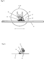
- the sawing tool 9, 14 is mounted with its saw head on a carriage 11 which is arranged on a horizontal rail 12 along the horizontal rail 12 movable in the direction of the double arrow.
- the horizontal rail 12 is in turn arranged movably on a substantially vertical rail pair 13 along the vertical rail pair 13.
- a pivot arm 10 is pivoted, wherein the pivot arm 10 carries at its free end the sawing tool 9, 14.
- the saw blade 17 of the sawing tool 9, 14 rotates during machining of the drum 6 about a pivot point which is in the region of the free end of the pivot arm 10, wherein the pivot arm 10 in turn at the same time about a pivot point which is in the region of the carriage 11, can be pivoted, in a plane parallel to the disk plane.
- the pivotability of the pivot arm 10 is preferably 360 ° in this plane.
- the rotary drive of the sawing tool 9, 14 is arranged either at the free end of the pivot arm 10 in order to shorten the transmission path for the torque from the rotary drive to the sawing tool 9, 14, or it is arranged on the saw head and with the sawing tool 9, 14 via a transmission connected, which bridges the pivot arm 10.
- the pivot drive for the pivot arm 10 is preferably arranged on the carriage 11.
- Hydraulic connections 16 are used to establish the connection between the saw head and external drive units. In the FIGS. 5 and 6 are not shown for reasons of clarity hose or cable feeders.
- the saw blade 17 is first set in rotation, and the pivot arm 10 is pivoted in the direction of the arrow.
- the saw blade 17 subsequently penetrates into the barrel 6 to be processed and separates it.
- the penetration depth can be chosen variable depending on the pivot position of the pivot arm 10.
- a horizontal feed movement along the indicated double arrow can be done by moving the carriage 11 along the horizontal rail 12.
- the sawing or milling tool 9, 14, 15 may further be equipped with a programmable controller, with the relevant operating parameters, such as peripheral speed, feed rate, feed and pivotal movements, and the travel paths and their sequence, are preprogrammed according to the respective processing situation can.
- the sawing or milling tool 9, 14, 15 perform the entire process independently and automatically, which brings significant advantages in the threatened by contamination working conditions.
- the invention thus provides a device for stripping, opening or trimming steel-coated barrels with concreted radioactive contents, with which the treatment of inhomogeneous and homogeneous barrels is possible, in particular steel-jacketed barrels with einbeton Arthurm radioactive content can be opened without water cooling, stripped and dressed , In this way, the storage volume and thus the storage costs for radioactive waste can be significantly reduced.
Landscapes
- Engineering & Computer Science (AREA)
- Physics & Mathematics (AREA)
- General Engineering & Computer Science (AREA)
- High Energy & Nuclear Physics (AREA)
- Mechanical Engineering (AREA)
- Environmental & Geological Engineering (AREA)
- Chemical & Material Sciences (AREA)
- Inorganic Chemistry (AREA)
- Plasma & Fusion (AREA)
- Mining & Mineral Resources (AREA)
- Processing Of Stones Or Stones Resemblance Materials (AREA)
Applications Claiming Priority (1)
| Application Number | Priority Date | Filing Date | Title |
|---|---|---|---|
| ATA50311/2018A AT520938B1 (de) | 2018-04-12 | 2018-04-12 | Fass-Zerlegeanlage |
Publications (2)
| Publication Number | Publication Date |
|---|---|
| EP3553791A1 true EP3553791A1 (fr) | 2019-10-16 |
| EP3553791B1 EP3553791B1 (fr) | 2020-08-05 |
Family
ID=65904019
Family Applications (1)
| Application Number | Title | Priority Date | Filing Date |
|---|---|---|---|
| EP19163873.3A Active EP3553791B1 (fr) | 2018-04-12 | 2019-03-19 | Installation de préhension et de découpe |
Country Status (2)
| Country | Link |
|---|---|
| EP (1) | EP3553791B1 (fr) |
| AT (1) | AT520938B1 (fr) |
Citations (3)
| Publication number | Priority date | Publication date | Assignee | Title |
|---|---|---|---|---|
| DE10111595A1 (de) * | 2001-01-09 | 2002-07-11 | Geraetebau Wiedtal Schuetzeich | Verfahren und Vorrichtung zum Auslösen eines Bohrkerns |
| DE102010034016A1 (de) * | 2010-08-11 | 2012-02-16 | Josef Hauck | Sicherung des Atommülls aus Atomkraftwerken zur Sicherung der Menschheit |
| FR3007883A1 (fr) * | 2013-06-27 | 2015-01-02 | Commissariat Energie Atomique | Installation et procede de manutention et decoupe de caisson contenant des produits radioactifs |
Family Cites Families (2)
| Publication number | Priority date | Publication date | Assignee | Title |
|---|---|---|---|---|
| JP4234631B2 (ja) * | 2004-04-05 | 2009-03-04 | 株式会社 エイブル | 円筒状構造物の除染および解体方法 |
| US9302294B2 (en) * | 2013-08-02 | 2016-04-05 | Babcock Noell Gmbh | Separating radioactive contaminated materials from cleared materials resulting from decommissioning a power plant |
-
2018
- 2018-04-12 AT ATA50311/2018A patent/AT520938B1/de not_active IP Right Cessation
-
2019
- 2019-03-19 EP EP19163873.3A patent/EP3553791B1/fr active Active
Patent Citations (3)
| Publication number | Priority date | Publication date | Assignee | Title |
|---|---|---|---|---|
| DE10111595A1 (de) * | 2001-01-09 | 2002-07-11 | Geraetebau Wiedtal Schuetzeich | Verfahren und Vorrichtung zum Auslösen eines Bohrkerns |
| DE102010034016A1 (de) * | 2010-08-11 | 2012-02-16 | Josef Hauck | Sicherung des Atommülls aus Atomkraftwerken zur Sicherung der Menschheit |
| FR3007883A1 (fr) * | 2013-06-27 | 2015-01-02 | Commissariat Energie Atomique | Installation et procede de manutention et decoupe de caisson contenant des produits radioactifs |
Also Published As
| Publication number | Publication date |
|---|---|
| EP3553791B1 (fr) | 2020-08-05 |
| AT520938B1 (de) | 2019-09-15 |
| AT520938A4 (de) | 2019-09-15 |
Similar Documents
| Publication | Publication Date | Title |
|---|---|---|
| DE102015120139B4 (de) | 3D-Drucker | |
| WO2008128502A2 (fr) | Dispositif de fabrication d'objets tridimensionnels | |
| DE3932145A1 (de) | Automatisierte anlage zum anbringen von mauerwerk auf einer wand | |
| DE2457624B2 (de) | Anlage zum Sortieren und Zerkleinern von radioaktiven Abfällen für eine Paketierpresse | |
| EP3450074A1 (fr) | Machine à scie à ruban | |
| EP2251178B1 (fr) | Dispositif pour échanger le cylindre à vis d'une extrudeuse | |
| WO2015185739A1 (fr) | Dispositif et procédé permettant d'enlever des matériaux contaminés | |
| EP2036676A2 (fr) | Dispositif de traitement de barriques avec des particules de dioxyde de carbone | |
| EP3553791B1 (fr) | Installation de préhension et de découpe | |
| EP1375755B1 (fr) | Appareil et procédé de enlever des cadres de obturation de regard de chausseé | |
| DE2531986A1 (de) | Spritzvorrichtung | |
| EP1105270B1 (fr) | Dispositif de fraisage permettant de travailler des surfaces de béton | |
| EP0169393B1 (fr) | Dispositif pour la production de forages d'une section transversale inaccessible | |
| DE3337549C2 (fr) | ||
| DE2756145A1 (de) | Dekontaminations-verfahren und -einrichtung | |
| DE102016117163B4 (de) | Fahrzeug für eine Vorrichtung zum Abtragen kontaminierter Flächen und Verfahren zum Abtragen kontaminierter Flächen | |
| DE102012107735B4 (de) | Vorrichtung zum Herstellen von Mauersteinen, insbesondere von mit Installationsschlitzen versehenen Mauersteinen, beispielsweise von Kalksandsteinen | |
| EP3066669B1 (fr) | Dispositif de réparation d'un dommage sur le fond d'un conteneur rempli d'eau | |
| CH622123A5 (en) | Device for embedding radioactive wastes in concrete in waste drums | |
| EP0031879B1 (fr) | Procédé d'incorporation de déchets radioactifs dans le béton dans des conteneurs à déchets | |
| WO2022003121A1 (fr) | Plate-forme de travail pour fours | |
| DE69612590T2 (de) | Vorrichtung zum einblasen von gasen oder fluiden stoffen und körnigen stoffen, insbesondere zum einblasen von sauerstoff in öfen zur stahlerzeugung | |
| DE19611357C2 (de) | Kantenbearbeitungsmaschine | |
| DE3244418C2 (de) | Verfahrenstechnische Anlage in heißen Zellen der Kerntechnik | |
| DE19505121C1 (de) | Vorrichtung zum Abtragen von Oberflächenschichten an Bauwerken |
Legal Events
| Date | Code | Title | Description |
|---|---|---|---|
| PUAI | Public reference made under article 153(3) epc to a published international application that has entered the european phase |
Free format text: ORIGINAL CODE: 0009012 |
|
| STAA | Information on the status of an ep patent application or granted ep patent |
Free format text: STATUS: THE APPLICATION HAS BEEN PUBLISHED |
|
| AK | Designated contracting states |
Kind code of ref document: A1 Designated state(s): AL AT BE BG CH CY CZ DE DK EE ES FI FR GB GR HR HU IE IS IT LI LT LU LV MC MK MT NL NO PL PT RO RS SE SI SK SM TR |
|
| AX | Request for extension of the european patent |
Extension state: BA ME |
|
| STAA | Information on the status of an ep patent application or granted ep patent |
Free format text: STATUS: REQUEST FOR EXAMINATION WAS MADE |
|
| 17P | Request for examination filed |
Effective date: 20200204 |
|
| RBV | Designated contracting states (corrected) |
Designated state(s): AL AT BE BG CH CY CZ DE DK EE ES FI FR GB GR HR HU IE IS IT LI LT LU LV MC MK MT NL NO PL PT RO RS SE SI SK SM TR |
|
| GRAP | Despatch of communication of intention to grant a patent |
Free format text: ORIGINAL CODE: EPIDOSNIGR1 |
|
| STAA | Information on the status of an ep patent application or granted ep patent |
Free format text: STATUS: GRANT OF PATENT IS INTENDED |
|
| RIC1 | Information provided on ipc code assigned before grant |
Ipc: B23D 45/00 20060101ALI20200302BHEP Ipc: G21F 5/14 20060101AFI20200302BHEP Ipc: G21D 1/00 20060101ALI20200302BHEP Ipc: G21F 9/30 20060101ALI20200302BHEP Ipc: G21F 9/28 20060101ALI20200302BHEP Ipc: B28D 1/04 20060101ALI20200302BHEP Ipc: G21F 9/36 20060101ALI20200302BHEP Ipc: B23D 45/12 20060101ALI20200302BHEP Ipc: G21F 5/005 20060101ALI20200302BHEP |
|
| INTG | Intention to grant announced |
Effective date: 20200326 |
|
| GRAS | Grant fee paid |
Free format text: ORIGINAL CODE: EPIDOSNIGR3 |
|
| GRAA | (expected) grant |
Free format text: ORIGINAL CODE: 0009210 |
|
| STAA | Information on the status of an ep patent application or granted ep patent |
Free format text: STATUS: THE PATENT HAS BEEN GRANTED |
|
| AK | Designated contracting states |
Kind code of ref document: B1 Designated state(s): AL AT BE BG CH CY CZ DE DK EE ES FI FR GB GR HR HU IE IS IT LI LT LU LV MC MK MT NL NO PL PT RO RS SE SI SK SM TR |
|
| REG | Reference to a national code |
Ref country code: GB Ref legal event code: FG4D Free format text: NOT ENGLISH |
|
| REG | Reference to a national code |
Ref country code: CH Ref legal event code: EP |
|
| REG | Reference to a national code |
Ref country code: AT Ref legal event code: REF Ref document number: 1299853 Country of ref document: AT Kind code of ref document: T Effective date: 20200815 |
|
| REG | Reference to a national code |
Ref country code: DE Ref legal event code: R096 Ref document number: 502019000112 Country of ref document: DE |
|
| REG | Reference to a national code |
Ref country code: IE Ref legal event code: FG4D Free format text: LANGUAGE OF EP DOCUMENT: GERMAN |
|
| REG | Reference to a national code |
Ref country code: CH Ref legal event code: NV Representative=s name: PATENTANWAELTE SCHAAD, BALASS, MENZL AND PARTN, CH |
|
| REG | Reference to a national code |
Ref country code: SE Ref legal event code: TRGR |
|
| REG | Reference to a national code |
Ref country code: FI Ref legal event code: FGE |
|
| REG | Reference to a national code |
Ref country code: LT Ref legal event code: MG4D |
|
| REG | Reference to a national code |
Ref country code: NL Ref legal event code: MP Effective date: 20200805 |
|
| PG25 | Lapsed in a contracting state [announced via postgrant information from national office to epo] |
Ref country code: PT Free format text: LAPSE BECAUSE OF FAILURE TO SUBMIT A TRANSLATION OF THE DESCRIPTION OR TO PAY THE FEE WITHIN THE PRESCRIBED TIME-LIMIT Effective date: 20201207 Ref country code: HR Free format text: LAPSE BECAUSE OF FAILURE TO SUBMIT A TRANSLATION OF THE DESCRIPTION OR TO PAY THE FEE WITHIN THE PRESCRIBED TIME-LIMIT Effective date: 20200805 Ref country code: BG Free format text: LAPSE BECAUSE OF FAILURE TO SUBMIT A TRANSLATION OF THE DESCRIPTION OR TO PAY THE FEE WITHIN THE PRESCRIBED TIME-LIMIT Effective date: 20201105 Ref country code: NO Free format text: LAPSE BECAUSE OF FAILURE TO SUBMIT A TRANSLATION OF THE DESCRIPTION OR TO PAY THE FEE WITHIN THE PRESCRIBED TIME-LIMIT Effective date: 20201105 Ref country code: GR Free format text: LAPSE BECAUSE OF FAILURE TO SUBMIT A TRANSLATION OF THE DESCRIPTION OR TO PAY THE FEE WITHIN THE PRESCRIBED TIME-LIMIT Effective date: 20201106 Ref country code: ES Free format text: LAPSE BECAUSE OF FAILURE TO SUBMIT A TRANSLATION OF THE DESCRIPTION OR TO PAY THE FEE WITHIN THE PRESCRIBED TIME-LIMIT Effective date: 20200805 Ref country code: LT Free format text: LAPSE BECAUSE OF FAILURE TO SUBMIT A TRANSLATION OF THE DESCRIPTION OR TO PAY THE FEE WITHIN THE PRESCRIBED TIME-LIMIT Effective date: 20200805 |
|
| PG25 | Lapsed in a contracting state [announced via postgrant information from national office to epo] |
Ref country code: NL Free format text: LAPSE BECAUSE OF FAILURE TO SUBMIT A TRANSLATION OF THE DESCRIPTION OR TO PAY THE FEE WITHIN THE PRESCRIBED TIME-LIMIT Effective date: 20200805 Ref country code: RS Free format text: LAPSE BECAUSE OF FAILURE TO SUBMIT A TRANSLATION OF THE DESCRIPTION OR TO PAY THE FEE WITHIN THE PRESCRIBED TIME-LIMIT Effective date: 20200805 Ref country code: PL Free format text: LAPSE BECAUSE OF FAILURE TO SUBMIT A TRANSLATION OF THE DESCRIPTION OR TO PAY THE FEE WITHIN THE PRESCRIBED TIME-LIMIT Effective date: 20200805 Ref country code: LV Free format text: LAPSE BECAUSE OF FAILURE TO SUBMIT A TRANSLATION OF THE DESCRIPTION OR TO PAY THE FEE WITHIN THE PRESCRIBED TIME-LIMIT Effective date: 20200805 Ref country code: IS Free format text: LAPSE BECAUSE OF FAILURE TO SUBMIT A TRANSLATION OF THE DESCRIPTION OR TO PAY THE FEE WITHIN THE PRESCRIBED TIME-LIMIT Effective date: 20201205 |
|
| PG25 | Lapsed in a contracting state [announced via postgrant information from national office to epo] |
Ref country code: EE Free format text: LAPSE BECAUSE OF FAILURE TO SUBMIT A TRANSLATION OF THE DESCRIPTION OR TO PAY THE FEE WITHIN THE PRESCRIBED TIME-LIMIT Effective date: 20200805 Ref country code: DK Free format text: LAPSE BECAUSE OF FAILURE TO SUBMIT A TRANSLATION OF THE DESCRIPTION OR TO PAY THE FEE WITHIN THE PRESCRIBED TIME-LIMIT Effective date: 20200805 Ref country code: CZ Free format text: LAPSE BECAUSE OF FAILURE TO SUBMIT A TRANSLATION OF THE DESCRIPTION OR TO PAY THE FEE WITHIN THE PRESCRIBED TIME-LIMIT Effective date: 20200805 Ref country code: RO Free format text: LAPSE BECAUSE OF FAILURE TO SUBMIT A TRANSLATION OF THE DESCRIPTION OR TO PAY THE FEE WITHIN THE PRESCRIBED TIME-LIMIT Effective date: 20200805 Ref country code: SM Free format text: LAPSE BECAUSE OF FAILURE TO SUBMIT A TRANSLATION OF THE DESCRIPTION OR TO PAY THE FEE WITHIN THE PRESCRIBED TIME-LIMIT Effective date: 20200805 |
|
| REG | Reference to a national code |
Ref country code: DE Ref legal event code: R097 Ref document number: 502019000112 Country of ref document: DE |
|
| PG25 | Lapsed in a contracting state [announced via postgrant information from national office to epo] |
Ref country code: AL Free format text: LAPSE BECAUSE OF FAILURE TO SUBMIT A TRANSLATION OF THE DESCRIPTION OR TO PAY THE FEE WITHIN THE PRESCRIBED TIME-LIMIT Effective date: 20200805 |
|
| PLBE | No opposition filed within time limit |
Free format text: ORIGINAL CODE: 0009261 |
|
| STAA | Information on the status of an ep patent application or granted ep patent |
Free format text: STATUS: NO OPPOSITION FILED WITHIN TIME LIMIT |
|
| PG25 | Lapsed in a contracting state [announced via postgrant information from national office to epo] |
Ref country code: SK Free format text: LAPSE BECAUSE OF FAILURE TO SUBMIT A TRANSLATION OF THE DESCRIPTION OR TO PAY THE FEE WITHIN THE PRESCRIBED TIME-LIMIT Effective date: 20200805 |
|
| 26N | No opposition filed |
Effective date: 20210507 |
|
| PG25 | Lapsed in a contracting state [announced via postgrant information from national office to epo] |
Ref country code: IT Free format text: LAPSE BECAUSE OF FAILURE TO SUBMIT A TRANSLATION OF THE DESCRIPTION OR TO PAY THE FEE WITHIN THE PRESCRIBED TIME-LIMIT Effective date: 20200805 |
|
| PG25 | Lapsed in a contracting state [announced via postgrant information from national office to epo] |
Ref country code: SI Free format text: LAPSE BECAUSE OF FAILURE TO SUBMIT A TRANSLATION OF THE DESCRIPTION OR TO PAY THE FEE WITHIN THE PRESCRIBED TIME-LIMIT Effective date: 20200805 |
|
| PG25 | Lapsed in a contracting state [announced via postgrant information from national office to epo] |
Ref country code: MC Free format text: LAPSE BECAUSE OF FAILURE TO SUBMIT A TRANSLATION OF THE DESCRIPTION OR TO PAY THE FEE WITHIN THE PRESCRIBED TIME-LIMIT Effective date: 20200805 |
|
| PG25 | Lapsed in a contracting state [announced via postgrant information from national office to epo] |
Ref country code: LU Free format text: LAPSE BECAUSE OF NON-PAYMENT OF DUE FEES Effective date: 20210319 Ref country code: IE Free format text: LAPSE BECAUSE OF NON-PAYMENT OF DUE FEES Effective date: 20210319 |
|
| PGFP | Annual fee paid to national office [announced via postgrant information from national office to epo] |
Ref country code: FI Payment date: 20220318 Year of fee payment: 4 Ref country code: CH Payment date: 20220323 Year of fee payment: 4 |
|
| PGFP | Annual fee paid to national office [announced via postgrant information from national office to epo] |
Ref country code: SE Payment date: 20220324 Year of fee payment: 4 Ref country code: BE Payment date: 20220228 Year of fee payment: 4 |
|
| PGFP | Annual fee paid to national office [announced via postgrant information from national office to epo] |
Ref country code: DE Payment date: 20230323 Year of fee payment: 5 |
|
| PG25 | Lapsed in a contracting state [announced via postgrant information from national office to epo] |
Ref country code: CY Free format text: LAPSE BECAUSE OF FAILURE TO SUBMIT A TRANSLATION OF THE DESCRIPTION OR TO PAY THE FEE WITHIN THE PRESCRIBED TIME-LIMIT Effective date: 20200805 |
|
| PG25 | Lapsed in a contracting state [announced via postgrant information from national office to epo] |
Ref country code: HU Free format text: LAPSE BECAUSE OF FAILURE TO SUBMIT A TRANSLATION OF THE DESCRIPTION OR TO PAY THE FEE WITHIN THE PRESCRIBED TIME-LIMIT; INVALID AB INITIO Effective date: 20190319 |
|
| PG25 | Lapsed in a contracting state [announced via postgrant information from national office to epo] |
Ref country code: FI Free format text: LAPSE BECAUSE OF NON-PAYMENT OF DUE FEES Effective date: 20230319 |
|
| REG | Reference to a national code |
Ref country code: CH Ref legal event code: PL Ref country code: SE Ref legal event code: EUG |
|
| GBPC | Gb: european patent ceased through non-payment of renewal fee |
Effective date: 20230319 |
|
| REG | Reference to a national code |
Ref country code: BE Ref legal event code: MM Effective date: 20230331 |
|
| PG25 | Lapsed in a contracting state [announced via postgrant information from national office to epo] |
Ref country code: GB Free format text: LAPSE BECAUSE OF NON-PAYMENT OF DUE FEES Effective date: 20230319 |
|
| PG25 | Lapsed in a contracting state [announced via postgrant information from national office to epo] |
Ref country code: SE Free format text: LAPSE BECAUSE OF NON-PAYMENT OF DUE FEES Effective date: 20230320 Ref country code: LI Free format text: LAPSE BECAUSE OF NON-PAYMENT OF DUE FEES Effective date: 20230331 Ref country code: GB Free format text: LAPSE BECAUSE OF NON-PAYMENT OF DUE FEES Effective date: 20230319 Ref country code: CH Free format text: LAPSE BECAUSE OF NON-PAYMENT OF DUE FEES Effective date: 20230331 |
|
| PG25 | Lapsed in a contracting state [announced via postgrant information from national office to epo] |
Ref country code: BE Free format text: LAPSE BECAUSE OF NON-PAYMENT OF DUE FEES Effective date: 20230331 |
|
| PG25 | Lapsed in a contracting state [announced via postgrant information from national office to epo] |
Ref country code: MK Free format text: LAPSE BECAUSE OF FAILURE TO SUBMIT A TRANSLATION OF THE DESCRIPTION OR TO PAY THE FEE WITHIN THE PRESCRIBED TIME-LIMIT Effective date: 20200805 |
|
| PG25 | Lapsed in a contracting state [announced via postgrant information from national office to epo] |
Ref country code: TR Free format text: LAPSE BECAUSE OF FAILURE TO SUBMIT A TRANSLATION OF THE DESCRIPTION OR TO PAY THE FEE WITHIN THE PRESCRIBED TIME-LIMIT Effective date: 20200805 |
|
| PG25 | Lapsed in a contracting state [announced via postgrant information from national office to epo] |
Ref country code: MT Free format text: LAPSE BECAUSE OF FAILURE TO SUBMIT A TRANSLATION OF THE DESCRIPTION OR TO PAY THE FEE WITHIN THE PRESCRIBED TIME-LIMIT Effective date: 20200805 |
|
| REG | Reference to a national code |
Ref country code: DE Ref legal event code: R119 Ref document number: 502019000112 Country of ref document: DE |
|
| PG25 | Lapsed in a contracting state [announced via postgrant information from national office to epo] |
Ref country code: DE Free format text: LAPSE BECAUSE OF NON-PAYMENT OF DUE FEES Effective date: 20241001 |
|
| PG25 | Lapsed in a contracting state [announced via postgrant information from national office to epo] |
Ref country code: DE Free format text: LAPSE BECAUSE OF NON-PAYMENT OF DUE FEES Effective date: 20241001 |
|
| PGFP | Annual fee paid to national office [announced via postgrant information from national office to epo] |
Ref country code: FR Payment date: 20250312 Year of fee payment: 7 |
|
| REG | Reference to a national code |
Ref country code: AT Ref legal event code: MM01 Ref document number: 1299853 Country of ref document: AT Kind code of ref document: T Effective date: 20240319 |
|
| PG25 | Lapsed in a contracting state [announced via postgrant information from national office to epo] |
Ref country code: AT Free format text: LAPSE BECAUSE OF NON-PAYMENT OF DUE FEES Effective date: 20240319 |