EP3553791B1 - Installation de préhension et de découpe - Google Patents
Installation de préhension et de découpe Download PDFInfo
- Publication number
- EP3553791B1 EP3553791B1 EP19163873.3A EP19163873A EP3553791B1 EP 3553791 B1 EP3553791 B1 EP 3553791B1 EP 19163873 A EP19163873 A EP 19163873A EP 3553791 B1 EP3553791 B1 EP 3553791B1
- Authority
- EP
- European Patent Office
- Prior art keywords
- tilting
- sawing
- rotating unit
- tool
- rotating
- Prior art date
- Legal status (The legal status is an assumption and is not a legal conclusion. Google has not performed a legal analysis and makes no representation as to the accuracy of the status listed.)
- Active
Links
Images

Classifications
-
- G—PHYSICS
- G21—NUCLEAR PHYSICS; NUCLEAR ENGINEERING
- G21D—NUCLEAR POWER PLANT
- G21D1/00—Details of nuclear power plant
- G21D1/003—Nuclear facilities decommissioning arrangements
-
- B—PERFORMING OPERATIONS; TRANSPORTING
- B23—MACHINE TOOLS; METAL-WORKING NOT OTHERWISE PROVIDED FOR
- B23D—PLANING; SLOTTING; SHEARING; BROACHING; SAWING; FILING; SCRAPING; LIKE OPERATIONS FOR WORKING METAL BY REMOVING MATERIAL, NOT OTHERWISE PROVIDED FOR
- B23D45/00—Sawing machines or sawing devices with circular saw blades or with friction saw discs
- B23D45/12—Sawing machines or sawing devices with circular saw blades or with friction saw discs with a circular saw blade for cutting tubes
- B23D45/124—Sawing machines or sawing devices with circular saw blades or with friction saw discs with a circular saw blade for cutting tubes the workpieces turning about their longitudinal axis during the cutting operations
-
- B—PERFORMING OPERATIONS; TRANSPORTING
- B28—WORKING CEMENT, CLAY, OR STONE
- B28D—WORKING STONE OR STONE-LIKE MATERIALS
- B28D1/00—Working stone or stone-like materials, e.g. brick, concrete or glass, not provided for elsewhere; Machines, devices, tools therefor
- B28D1/02—Working stone or stone-like materials, e.g. brick, concrete or glass, not provided for elsewhere; Machines, devices, tools therefor by sawing
- B28D1/04—Working stone or stone-like materials, e.g. brick, concrete or glass, not provided for elsewhere; Machines, devices, tools therefor by sawing with circular or cylindrical saw-blades or saw-discs
- B28D1/044—Working stone or stone-like materials, e.g. brick, concrete or glass, not provided for elsewhere; Machines, devices, tools therefor by sawing with circular or cylindrical saw-blades or saw-discs the saw blade being movable on slide ways
-
- G—PHYSICS
- G21—NUCLEAR PHYSICS; NUCLEAR ENGINEERING
- G21F—PROTECTION AGAINST X-RADIATION, GAMMA RADIATION, CORPUSCULAR RADIATION OR PARTICLE BOMBARDMENT; TREATING RADIOACTIVELY CONTAMINATED MATERIAL; DECONTAMINATION ARRANGEMENTS THEREFOR
- G21F5/00—Transportable or portable shielded containers
- G21F5/005—Containers for solid radioactive wastes, e.g. for ultimate disposal
-
- G—PHYSICS
- G21—NUCLEAR PHYSICS; NUCLEAR ENGINEERING
- G21F—PROTECTION AGAINST X-RADIATION, GAMMA RADIATION, CORPUSCULAR RADIATION OR PARTICLE BOMBARDMENT; TREATING RADIOACTIVELY CONTAMINATED MATERIAL; DECONTAMINATION ARRANGEMENTS THEREFOR
- G21F5/00—Transportable or portable shielded containers
- G21F5/06—Details of, or accessories to, the containers
- G21F5/14—Devices for handling containers or shipping-casks, e.g. transporting devices loading and unloading, filling of containers
-
- G—PHYSICS
- G21—NUCLEAR PHYSICS; NUCLEAR ENGINEERING
- G21F—PROTECTION AGAINST X-RADIATION, GAMMA RADIATION, CORPUSCULAR RADIATION OR PARTICLE BOMBARDMENT; TREATING RADIOACTIVELY CONTAMINATED MATERIAL; DECONTAMINATION ARRANGEMENTS THEREFOR
- G21F9/00—Treating radioactively contaminated material; Decontamination arrangements therefor
- G21F9/28—Treating solids
- G21F9/30—Processing
- G21F9/301—Processing by fixation in stable solid media
- G21F9/302—Processing by fixation in stable solid media in an inorganic matrix
- G21F9/304—Cement or cement-like matrix
-
- G—PHYSICS
- G21—NUCLEAR PHYSICS; NUCLEAR ENGINEERING
- G21F—PROTECTION AGAINST X-RADIATION, GAMMA RADIATION, CORPUSCULAR RADIATION OR PARTICLE BOMBARDMENT; TREATING RADIOACTIVELY CONTAMINATED MATERIAL; DECONTAMINATION ARRANGEMENTS THEREFOR
- G21F9/00—Treating radioactively contaminated material; Decontamination arrangements therefor
- G21F9/28—Treating solids
- G21F9/34—Disposal of solid waste
- G21F9/36—Disposal of solid waste by packaging; by baling
-
- Y—GENERAL TAGGING OF NEW TECHNOLOGICAL DEVELOPMENTS; GENERAL TAGGING OF CROSS-SECTIONAL TECHNOLOGIES SPANNING OVER SEVERAL SECTIONS OF THE IPC; TECHNICAL SUBJECTS COVERED BY FORMER USPC CROSS-REFERENCE ART COLLECTIONS [XRACs] AND DIGESTS
- Y02—TECHNOLOGIES OR APPLICATIONS FOR MITIGATION OR ADAPTATION AGAINST CLIMATE CHANGE
- Y02E—REDUCTION OF GREENHOUSE GAS [GHG] EMISSIONS, RELATED TO ENERGY GENERATION, TRANSMISSION OR DISTRIBUTION
- Y02E30/00—Energy generation of nuclear origin
Definitions
- the invention relates to a device for stripping, opening or dressing steel-clad drums with radioactive content concreted in, according to the preamble of claim 1.
- Radioactive waste has been collected, treated and stored for more than five decades.
- the aim of the measures is the chemical stabilization and a safe inclusion of the radionuclides in the forms of waste, and to achieve the lowest possible volume of waste, since the intermediate and final storage is associated with considerable costs.
- Devices for stripping, opening or dressing steel-clad drums with radioactive content concreted in were about in the FR 3 007 883 A1 described. Methods and devices for triggering a drill core have been described in the DE 101 11 595 A1 described.
- inhomogeneous cementing waste is mostly poured loosely into 100 1 drums. These barrels are closed with a lid, placed in a 200 1 barrel and the space in between is filled with concrete. This procedure was chosen in the past due to the lack of conditioning facilities for combustible and liquid radioactive waste, but would no longer be permissible from today's perspective.
- the barrels created in this way are also referred to below as inhomogeneous barrels. Acting with both homogeneous and inhomogeneous barrels it is steel-clad drums with radioactive content encased in concrete.
- post-conditioning and reconditioning In order to be able to guarantee long-term stable interim storage, suitable additional measures (“post-conditioning and reconditioning”) must be taken.
- post-conditioning and reconditioning For example, for the aftertreatment of homogeneously cemented waste containers, it has been proposed to place the container in suitable over drums, the water present possibly having to be removed beforehand by a drying process in order to reduce the reaction and corrosion potential.
- Modern drums for conditioned waste have a fully glued inner liner made of glass fiber reinforced plastic with sufficient thickness. This ensures that the interior paintwork is not damaged during loading.
- care must be taken with regard to transhipment that a sufficiently thick, pre-compacted, dry sand layer is placed in the barrel bottom before the 200-1 barrel can be adjusted. The cavity must then be filled with sand and compressed. This procedure must be repeated until the drum is filled to the brim. This is the only way to achieve a reasonably safe positioning of the inner barrel in order to avoid damage to the outer barrel.
- the steel-coated concrete core is "drilled over" by means of a diamond drill bit, that is to say a drilling is carried out in an axial feed movement between the outer steel jacket and the concrete core.
- the reduced-diameter concrete core can subsequently be placed in a new barrel.
- water is added when working with diamond core drilling systems. Approx. 200 liters of water must be added per drilling process.
- the diamond drill bit When drilling vertically in the barrel, the diamond drill bit "runs” again and again due to excessive play in the slide guides. The resulting poor guidance of the diamond core bit in the borehole leads to jamming of the core bit.
- a major disadvantage of reconditioning and postconditioning using wet core drilling is the large amount of secondary waste that results in additional processing and conditioning costs for water treatment or for compacting and drying sludge and concrete breakage.
- a further disadvantage is that the wet-drilled concrete cylinders must also be dried and associated additional costs.
- a high level of decontamination is also to be expected for revision and maintenance work.
- Another disadvantage is the short tool life compared to other process technologies, the increased space requirement of the system technology and the susceptibility to errors.
- Claim 1 relates to a device for stripping, opening or dressing steel-clad barrels with concrete-encased radioactive content, in which it is proposed according to the invention that a processing chamber with a transfer opening for the barrels is provided, and a tilting and rotating unit arranged in the processing chamber for receiving the barrels, a barrel accommodated with its longitudinal axis parallel to a longitudinal extent of the tilting and rotating unit being rotatable about its longitudinal axis by the tilting and rotating unit, and the tilting and rotating unit from an upright position with a substantially vertical longitudinal extent of the tilting and and the rotating unit can be tilted into a lying position with a substantially horizontal longitudinal extent of the tilting and rotating unit, and at least two sawing or milling tools are provided, at least one sawing or milling tool for stripping, opening or dressing the barrel when the tilting position is upright -u nd rotating unit in its feed movement is guided transversely to the longitudinal extension of the tilting and rotating unit, and at least one sawing
- Over-drilling of the barrels is not used, instead the barrels are processed on the one hand with a feed movement of the sawing or milling tool transverse to the longitudinal extension of the tilting or turning tool with the tilting and turning unit in an upright position, and on the other hand with one along the longitudinal extension of the tilting and rotating unit, feed movement of the sawing or milling tool when the tilting and rotating unit is in a lying position.
- the processing of the barrels takes place from the outside, whereby sawing or milling tools can be used that do not require water cooling.
- the processing concept according to the invention enables the barrels to be broken down dry, which was previously considered impossible.
- the now opened barrel can be tilted into a lying position by means of the tilting and rotating unit in order to be able to examine and 'clear out the radioactive content.
- the waste can be removed and treated in accordance with today's requirements, for example by burning combustible waste, by chemical-physical treatment of aqueous liquids, or by compacting solid, non-combustible waste.
- the concrete jacket can be checked for contamination and cut into transportable or storable parts.
- the disassembled parts of the barrel are treated according to their nature, for example by remelting the steel sheets.
- Disassembling the Sheath parts in sheath segments take place when the tilting and rotating unit is in a lying position, which corresponds to a lying position of the barrel, with the feed movement of the sawing or milling tool that is guided along the longitudinal extent of the tilting and rotating unit.
- This feed movement is also referred to below as an axial cut, even if the feed movement does not have to run exactly axially.
- the steel jacket of the drum can be cut into the bottom area with the feed movement of the sawing or milling tool which is transverse to the longitudinal extension of the tilting and rotating unit. Subsequently, the drum can be tilted into a lying position using the tilting and rotating unit. In the lying position of the tilting and rotating unit, which corresponds to a lying position of the barrel, the steel jacket can be cut open by axial cuts with an advancing movement of the sawing or milling tool along the longitudinal extent of the tilting and rotating unit. The radial cut in the base area previously created creates jacket segments that can be easily removed manually.
- the concrete casing can be milled with a further feed movement of the sawing or milling tool along the longitudinal extension of the tilting and rotating unit in order to reduce its diameter and to be able to repack the concrete core thus prepared into a new barrel.
- the default is to remove a layer of about 10 mm on the outside.
- the processing in the lying position of the barrel also makes it possible to machine the barrel over its entire longitudinal extent, which would be difficult or difficult to do in an upright position.
- the cutting of the steel jacket and the milling of the concrete core with the barrel in the respective lying position could be carried out with the same saw or milling tool holder after exchanging the sawing tool for a milling tool.
- two rotating saw or Milling tools for stripping, opening or dressing the barrel when the tilting and rotating unit is in a horizontal position are provided, each of which can be moved along the longitudinal extent of the tilting and rotating unit, one of the two sawing or milling tools being one along the longitudinal extent of the tilting and Rotary unit-guided sawing tool is designed with a horizontal plane of rotation, and one of the two sawing or milling tools is designed as a milling tool with a vertical plane of rotation along the longitudinal extent of the tilting and rotating unit.
- the sawing tool and the milling tool are arranged on opposite sides of the tilting and rotating unit, the sawing tool making axial cuts and thus severing the barrel casing in the axial direction, and the milling tool milling off the concrete core from the outside in the case of inhomogeneous barrels.
- These processes are supported by the tilting and rotating unit by rotating the barrel around its longitudinal axis through an angle of, for example, 120 ° when an axial cut is made in order to then make a new axial cut.
- the barrel can be rotated around its longitudinal axis using the tilting and rotating unit to support the milling process.
- a rotating saw tool which is guided transversely to the longitudinal extent of the tilting and rotating unit, is provided for stripping, opening or dressing the barrel when the tilting and rotating unit is in an upright position with a horizontal plane of rotation.
- This sawing tool performs the feed movement provided according to the invention transversely to the longitudinal extension of the tilting and rotating unit, which is also referred to here as a radial cut, for example in order to cut the barrel in the lid area in the case of inhomogeneous barrels, or to cut the steel jacket of the barrel in the bottom area in the case of homogeneous barrels.
- the sawing or milling tools are preferably each mounted on a horizontally movable slide. With the sawing or milling tools provided for the processing of the barrels in their lying position, this storage serves to guide the feed movement of the sawing or milling tools along the longitudinal extent of the tilting and rotating unit.
- the slide is guided on a rail, which is next to the tilting or rotating unit in its lying position extends horizontally.
- the horizontal slide serves to move the sawing tool from a lateral parking position into a processing position arranged in the middle of the rail.
- This slide is guided, for example, on a rail which extends horizontally in the area of the take-over opening, but at right angles to the two rails mentioned above.
- the sawing or milling tools are preferably rotating sawing or milling tools, each of which is guided by a swivel arm with a swivel axis perpendicular to the plane of rotation of the respective sawing or milling tool.
- the swivel arm is articulated on the above-mentioned slide, and the sawing or milling tool is attached to the opposite, free end of the swivel arm.
- the sawing tools with a horizontal plane of rotation can thus each be pivoted about a vertical pivot axis, and the milling tool with a vertical plane of rotation can be pivoted about a horizontal pivot axis, the pivoting arm preferably being pivotable in each case through 360 °.
- the contact pressure of the saw or milling tool is ensured via the swivel arm, i.e. the movement of the saw or milling tools penetrating into the barrel in the radial direction.
- the at least one sawing or milling tool is mounted on a vertically movable slide.
- this vertically movable mounting of the sawing tool is advantageous, since this sawing or milling tool has to cut the barrel in the lid area in the case of inhomogeneous barrels, and in the case of homogeneous barrels The steel jacket of the barrel has to cut into the bottom area, and thus processing of the barrel at different heights is necessary.
- the vertical mobility can also be used to adjust the height of the barrel.
- this is vertical Movable storage advantageous, for example, to be able to process drums of different diameters.
- the processing chamber be provided with a closable roof opening.
- This roof opening is used, for example, when lifting inhomogeneous barrels to lift the separated lid area when the barrel is in a standing position or lifted concrete parts out of the processing chamber with the barrel in a lying position.
- the closable roof opening can be designed as a wing or sliding ceiling.
- the rotating sawing or milling tools are provided with dust extraction in their peripheral region.
- This dust extraction system includes protective hoods for the sawing or milling tools, as well as an extraction system, so that sawing or milling dust can be extracted into a filter system, for example via a cyclone pre-separator.
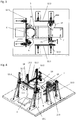
- the 1 to 4 Reference which show an embodiment of the device according to the invention, wherein the 1 and 2 show the side walls 1 and the roof 2 of the processing chamber, and in the 3 and 4 the side walls 1 and the roof 2 have been omitted.
- the device is built on a base plate 3 designed as a sealed stainless steel trough.
- the processing chamber is soundproof and equipped with two wing gates on the front and rear, one wing door of which forms a transfer opening for transporting the barrels 6 into the processing chamber, and the second wing gate enables the radioactive content of inhomogeneous barrels 6 to be transported away.
- the processing chamber is loaded on the side of the take-over opening, and transport carriages 4 can be provided in order to move the barrel 6 to the tilting and rotating unit 5 at a suitable height. Furthermore, the processing chamber is provided with a closable roof opening, which can be designed, for example, as a wing cover or sliding ceiling, in order to be able to remove concrete parts from the processing chamber using a lifting device such as a crane and the like.
- a mobile collecting cup 7 made of stainless steel can also be seen in order to be able to remove the contents of the inhomogeneous barrels.
- This collecting cup 7 is designed such that it can be pushed under the tilting and rotating unit 5 in order to avoid contamination being carried over.
- the tilting and rotating unit 5 has a receptacle which partially encompasses the casing of a receptacle 6 and has a concave receptacle surface, the receptacle being provided with rotating rollers which project beyond the receptacle surface.
- the recorded barrel 6 lies against the rotating rollers and is rotated by them about its longitudinal axis.
- the barrel 6 rests on a turntable 8 of the tilting and rotating unit 5, bearing rollers being able to be provided in order to facilitate the rotary movement.
- the tilting and rotating unit 5 is designed such that it can be tilted so that the barrel 6 moves from an upright position to a lying position (see the dashed position of the tilting and rotating unit 5 in FIGS Fig.
- the barrel 6 can be rotated by the rotating rollers in an upright and lying position during processing.
- the rotating rollers can be designed such that the barrel 6 exerts a moment in the direction of the turntable 8 in the upright position during the rotational movement about its longitudinal axis. If this moment is not enough, an additional swiveling pressure roller can be installed.
- the dead weight of the barrel 6 is sufficient to generate the necessary contact pressure.
- the tilting and rotating unit 5 is tilted slightly from the vertical in its upright position, so that the barrel 6 rests on the rotating rollers with part of its own weight and thus increases the contact pressure. In the horizontal position of the barrel 6, the barrel 6 rests with its entire weight on the rotating rollers anyway, which ensures a sufficient contact pressure.
- a first, rotating sawing tool 9 is provided for stripping, opening or dressing the barrel 6 when the tilting and rotating unit 5 is in an upright position with a horizontal plane of rotation.
- This Saw tool 9 executes the feed movement provided according to the invention transversely to the longitudinal extent of the tilting and rotating unit 5, which is also referred to here as a radial section, for example in order to cut the barrel 6 in the lid area in the case of inhomogeneous barrels 6, or the steel jacket of the barrel 6 in the case of homogeneous barrels 6 Cut the floor area.
- This saw tool 9 is equipped with a swivel arm 10.1 which dips the saw blade into the barrel 6.
- the swivel arm 10.1 is mounted on a backlash-free slide 11.1 and can be positioned horizontally continuously using a horizontal rail 12.1 and vertically using a substantially vertical pair of rails 13.1.
- the first sawing tool 9 is operated with an output of 18 kW and a drive speed of at most 1200 rpm with a saw blade diameter of at most 800 mm.
- a drilling unit 18 can be arranged to be horizontally movable on the horizontal rail 12.1.
- the drilling unit 18 is in a lateral parking position during the cutting process and is positioned above the barrel 6 if necessary. In this case, the sawing tool 9 is moved into a lateral parking position at the rail end.
- the drilling unit 18 is used to drill anchor holes in the barrel 6 in order to be able to remove the re-erected, trimmed concrete jacket from the processing chamber more easily and to insert it into new receptacles.
- the feed movement of the drilling unit 18 takes place via the height adjustment of the sawing tool 9 using the vertical rails 13.1.
- the drilling unit 18 is operated with an output of 3.7 kW, a speed of 340-2580 rpm and a drilling range of 20-280 mm.
- a second sawing tool 14 with a horizontal plane of rotation and a milling tool 15 with a vertical plane of rotation are provided, each of which can be moved along the longitudinal extent of the tilting and rotating unit 5.
- the second sawing tool 14 and the milling tool 15 are arranged on opposite sides of the tilting and rotating unit 5, the second Saw tool 14 sets axial cuts and thus cuts the barrel jacket in the axial direction, and the milling tool 15 mills the concrete core from the outside in the case of inhomogeneous barrels.
- the tilting and rotating unit 5 by rotating the barrel 6 around its longitudinal axis through an angle of, for example, 120 ° when an opening is made to cut the jacket after an axial cut, and then to make a new axial cut.
- the barrel 6 can be rotated about its longitudinal axis with the aid of the tilting and rotating unit 5 in order to support the milling process.
- the cutting movement of the second sawing tool 14 is carried out via a slide 11.2 which is guided horizontally with the aid of a horizontal rail 12.2, so that the saw blade of the second sawing tool 14 remains at the desired cutting depth.
- the depth infeed is carried out via a swivel arm 10.2.
- the second sawing tool 14 can be positioned vertically continuously with the aid of an essentially vertical pair of rails 13.2.
- the sawing tools 9, 14 are equipped with a coated saw blade in order to ensure dry machining at the desired immersion depth. Both sawing tools 9, 14 are also provided with dust extraction. This dust extraction includes protective hoods for the sawing tools 9, 14, and an extraction system, so that sawdust can be extracted into a filter system, for example via a cyclone pre-separator.
- Both sawing tools 9, 14 can also be equipped with a flush flange. This flush flange makes saw blade changes easier and enables a one-man assembly of the saw blade.
- the sawing tools 9, 14 are mounted in such a way that the saw blade can be changed from above.
- a saw module is used as the milling tool 15, the saw blade being replaced by a milling disk.
- PDK segments are arranged tangentially on this milling disk in order to remove the concrete core dry.
- the maximum immersion depth per work step is 5mm.
- This milling disc is also equipped with a protective hood to enable dust-free machining.
- the depth infeed takes place via a swivel arm 10.3 and Feed movement via a play-free slide 11.3, which is guided horizontally via a horizontal rail 12.3.
- the milling tool 15 can be positioned vertically continuously using an essentially vertical pair of rails 13.3.
- the operating data correspond to that of the saw modules.
- the diameter of the concrete core is measured using a light barrier.
- dust extraction includes a cyclone pre-separator and an extraction system.
- the suction system is equipped with HEPA filters and has a suction capacity of 800 m 3 / h.
- the milling tool 15 as well as the sawing tools 9, 14 are connected to this system via an electro-pneumatically controlled distributor.
- the dust extractor has a tight, lockable sealing nozzle to prevent contamination from spreading.
- the grinding or cutting dust is disposed of in an endless hose.
- the cyclone pre-separator is designed for installation on press cartridges.
- the tool drives for the sawing tools 9, 14, the milling tool 15 and the drilling unit are water-cooled electric motors with a plug connection, which can be cleaned with jet water.
- the tool drives are identical in construction and interchangeable.
- the feed motors for the sawing tools 9, 14, the milling tool 15 and the drilling unit are also permanent magnet synchronous motors and are interchangeable.
- the water cooling of the tool drives can take place in a closed cooling circuit.
- the control is implemented with a PLC.
- the tool drives of the sawing tools 9, 14, the milling tool 15 and the drilling unit are controlled by frequency converters and allow the drives to be regulated continuously. Communication between the PLC and the frequency converter takes place via PROFINET.
- the cables of the tool drives are guided in energy chains on the frame.
- a mobile control panel is provided for operation.
- the input of the operating parameters and the display of the operating parameters is implemented via a touch panel and is installed in the control panel.
- a mobile control box can be provided for adjustment work in the processing chamber.
- This control box is secured by a key switch on the control panel. This key switch unlocks the work area for maintenance work.
- a camera system with high-resolution, remote-controlled cameras is installed. These cameras are equipped with microphones to monitor the development of noise. The camera lens is also protected with an air curtain.
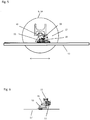
- the saw tool 9, 14 is mounted with its saw head on a slide 11 which is arranged on a horizontal rail 12 along the horizontal rail 12 so as to be movable in the direction of the double arrow.
- the horizontal rail 12 is in turn arranged to be movable on an essentially vertical pair of rails 13 along the vertical pair of rails 13.
- a swivel arm 10 is pivotally articulated on the saw head, the swivel arm 10 carrying the sawing tool 9, 14 at its free end.
- the saw blade 17 of the sawing tool 9, 14 rotates during the processing of the barrel 6 about a fulcrum which is located in the region of the free end of the swivel arm 10, the swivel arm 10 in turn at the same time about a fulcrum which is in the region of the slide 11, can be pivoted, in a plane parallel to the disc plane.
- the pivotability of the swivel arm 10 is preferably 360 ° in this plane.
- the rotary drive of the sawing tool 9, 14 is either arranged at the free end of the swivel arm 10 in order to shorten the transmission path for the torque from the rotary drive to the sawing tool 9, 14, or it is arranged on the saw head and with the sawing tool 9, 14 via a gear connected, which bridges the swivel arm 10.
- the swivel drive for the swivel arm 10 is preferably arranged on the carriage 11.
- Hydraulic connections 16 serve to establish a connection between the saw head and external drive units.
- hose or cable feeds are not shown for reasons of clarity.
- the saw blade 17 is first set in rotation, and the swivel arm 10 is pivoted in the direction of the arrow.
- the saw blade 17 subsequently penetrates into the barrel 6 to be machined and separates it.
- the depth of penetration can be selected variably depending on the swivel position of the swivel arm 10.
- a horizontal feed movement along the double arrow shown can be carried out by moving the carriage 11 along the horizontal rail 12.
- the sawing or milling tool 9, 14, 15 can also be equipped with a programmable control with which the relevant operating parameters, such as circumferential speed, feed speed, feed and swivel movements, as well as the travel paths and their sequence, are preprogrammed in accordance with the respective machining situation can.
- the sawing or milling tool 9, 14, 15 can thus carry out the entire machining process independently and automatically, which brings considerable advantages in the working conditions threatened by contamination.
- a device for stripping, opening or dressing steel-clad barrels with embedded radioactive content is thus provided, with which the treatment of inhomogeneous and homogeneous barrels is possible, in particular steel-clad barrels with encased radioactive content being able to be opened, stripped and trimmed without the need for water cooling .
- the storage volume and thus the storage costs for radioactive waste can be significantly reduced.
Landscapes
- Engineering & Computer Science (AREA)
- Physics & Mathematics (AREA)
- General Engineering & Computer Science (AREA)
- High Energy & Nuclear Physics (AREA)
- Mechanical Engineering (AREA)
- Environmental & Geological Engineering (AREA)
- Chemical & Material Sciences (AREA)
- Inorganic Chemistry (AREA)
- Plasma & Fusion (AREA)
- Mining & Mineral Resources (AREA)
- Processing Of Stones Or Stones Resemblance Materials (AREA)
Claims (9)
- Dispositif pour désenvelopper, ouvrir ou débiter des fûts (6) ayant une enveloppe en acier et contenant des matières radioactives scellées dans du béton, dans lequel il est prévu une chambre de traitement avec une ouverture de réception pour les fûts (6) ainsi qu'une unité basculante et rotative (5) disposée dans la chambre de traitement pour recevoir les fûts (6), dans lequel un fût (6) reçu avec son axe longitudinal parallèle à une extension longitudinale de l'unité basculante et rotative (5) peut être tourné autour de son axe longitudinal par l'unité basculante et rotative (5), et l'unité basculante et rotative (5) peut être basculée d'une position debout avec une extension longitudinale sensiblement verticale de l'unité basculante et rotative (5) dans une position couchée avec une extension longitudinale sensiblement horizontale de l'unité basculante et rotative (5) ,
caractérisé en ce qu'il est prévu au moins deux outils de sciage ou de fraisage (9, 14, 15), au moins un outil de sciage ou de fraisage (9) pour désenvelopper, ouvrir ou débiter le fût (6) étant guidé dans son mouvement d'avance transversalement à l'extension longitudinale de l'unité basculante et rotative (5) lorsque l'unité basculante et rotative (5) est en position debout, et au moins un outil de sciage ou de fraisage (14, 15) pour désenvelopper, ouvrir ou débiter le fût (6) étant guidé dans son mouvement d'avance suivant l'extension longitudinale de l'unité basculante et rotative (5) lorsque l'unité basculante et rotative (5) est en position couchée. - Dispositif selon la revendication 1, caractérisé en ce que deux outils de sciage ou de fraisage rotatifs (14, 15) sont prévus pour désenvelopper, ouvrir ou débiter le fût (6) lorsque l'unité basculante et rotative (5) est en position couchée, l'un des deux outils de sciage ou de fraisage (14, 15) étant conçu comme un outil de sciage (14) à plan de rotation horizontal et guidé suivant l'extension longitudinale de l'unité basculante et rotative (5), et l'un des deux outils de sciage ou de fraisage (14, 15) étant conçu comme un outil de fraisage (15) à plan de rotation vertical et guidé suivant l'extension longitudinale de l'unité basculante et rotative (5).
- Dispositif selon la revendication 1 ou 2, caractérisé en ce qu'un outil de sciage rotatif (9), guidé transversalement à l'extension longitudinale de l'unité basculante et rotative (5) pour désenvelopper, ouvrir ou débiter le fût (6) lorsque l'unité basculante et rotative (5) est en position debout, est prévu avec un plan de rotation horizontal.
- Dispositif selon l'une des revendications 1 à 3, caractérisé en ce que les outils de sciage ou de fraisage (9, 14, 15) sont chacun montés sur un chariot (11) mobile horizontalement.
- Dispositif selon l'une des revendications 1 à 4, caractérisé en ce qu'il est prévu des outils de sciage ou de fraisage rotatifs (9, 14, 15) qui sont guidés chacun par un bras pivotant (10) dont l'axe de pivotement est perpendiculaire au plan de rotation de l'outil de sciage ou de fraisage respectif (9, 14, 15).
- Dispositif selon l'une des revendications 1 à 5, caractérisé en ce qu'au moins un outil de sciage ou de fraisage (9, 14, 15) est monté sur un chariot (11) mobile verticalement.
- Dispositif selon l'une des revendications 1 à 6, caractérisé en ce que la chambre de traitement est pourvue d'une ouverture de toit pouvant être fermée.
- Dispositif selon l'une des revendications 1 à 7, caractérisé en ce que les outils de sciage ou de fraisage rotatifs (9, 14, 15) sont pourvus d'une aspiration des poussières dans leur zone périphérique.
- Dispositif selon l'une des revendications 1 à 8, caractérisé en ce que l'unité basculante et rotative (5) présente une partie de réception avec une surface de réception concave qui entoure partiellement l'enveloppe d'un fût reçu (6), la partie de réception étant pourvue de rouleaux rotatifs s'étendant au-delà de la surface de réception.
Applications Claiming Priority (1)
| Application Number | Priority Date | Filing Date | Title |
|---|---|---|---|
| ATA50311/2018A AT520938B1 (de) | 2018-04-12 | 2018-04-12 | Fass-Zerlegeanlage |
Publications (2)
| Publication Number | Publication Date |
|---|---|
| EP3553791A1 EP3553791A1 (fr) | 2019-10-16 |
| EP3553791B1 true EP3553791B1 (fr) | 2020-08-05 |
Family
ID=65904019
Family Applications (1)
| Application Number | Title | Priority Date | Filing Date |
|---|---|---|---|
| EP19163873.3A Active EP3553791B1 (fr) | 2018-04-12 | 2019-03-19 | Installation de préhension et de découpe |
Country Status (2)
| Country | Link |
|---|---|
| EP (1) | EP3553791B1 (fr) |
| AT (1) | AT520938B1 (fr) |
Family Cites Families (5)
| Publication number | Priority date | Publication date | Assignee | Title |
|---|---|---|---|---|
| DE10111595A1 (de) * | 2001-01-09 | 2002-07-11 | Geraetebau Wiedtal Schuetzeich | Verfahren und Vorrichtung zum Auslösen eines Bohrkerns |
| JP4234631B2 (ja) * | 2004-04-05 | 2009-03-04 | 株式会社 エイブル | 円筒状構造物の除染および解体方法 |
| DE102010034016A1 (de) * | 2010-08-11 | 2012-02-16 | Josef Hauck | Sicherung des Atommülls aus Atomkraftwerken zur Sicherung der Menschheit |
| FR3007883B1 (fr) * | 2013-06-27 | 2015-07-17 | Commissariat Energie Atomique | Installation et procede de manutention et decoupe de caisson contenant des produits radioactifs |
| US9302294B2 (en) * | 2013-08-02 | 2016-04-05 | Babcock Noell Gmbh | Separating radioactive contaminated materials from cleared materials resulting from decommissioning a power plant |
-
2018
- 2018-04-12 AT ATA50311/2018A patent/AT520938B1/de not_active IP Right Cessation
-
2019
- 2019-03-19 EP EP19163873.3A patent/EP3553791B1/fr active Active
Non-Patent Citations (1)
| Title |
|---|
| None * |
Also Published As
| Publication number | Publication date |
|---|---|
| AT520938B1 (de) | 2019-09-15 |
| AT520938A4 (de) | 2019-09-15 |
| EP3553791A1 (fr) | 2019-10-16 |
Similar Documents
| Publication | Publication Date | Title |
|---|---|---|
| EP2056983B1 (fr) | Procédé de maintenance d'une fermeture coulissante montée au niveau du bec d'un récipient pour bain de fusion | |
| DE3002696A1 (de) | Vorrichtung zum feinzerkleinern radioaktiven abfalls | |
| DE102014004075A1 (de) | Robotersystem | |
| DE2457624B2 (de) | Anlage zum Sortieren und Zerkleinern von radioaktiven Abfällen für eine Paketierpresse | |
| DE102014210947B3 (de) | Vorrichtung und Verfahren zum Abtragen von kontaminiertem Material | |
| DE2502392C3 (de) | Anlage zur Oberflächenbehandlung von schweren Metallbrammen | |
| EP3553791B1 (fr) | Installation de préhension et de découpe | |
| DE2531986A1 (de) | Spritzvorrichtung | |
| EP1375755A1 (fr) | Appareil et procédé de enlever des cadres de obturation de regard de chausseé | |
| DE2144121A1 (de) | Müllverbrennungs-Drehofen | |
| EP0169393B1 (fr) | Dispositif pour la production de forages d'une section transversale inaccessible | |
| DE3337549C2 (fr) | ||
| EP1105270A1 (fr) | Dispositif de fraisage permettant de travailler des surfaces de beton et procede de fraisage associe | |
| DE2756145A1 (de) | Dekontaminations-verfahren und -einrichtung | |
| DE2540162C3 (de) | Verfahren zur Herstellung eines mineralischen Bindemittels und Vorrichtung zur Herstellung desselben | |
| DE4428501A1 (de) | Vorrichtung und Verfahren zur Demontage eines Behälters, insbesondere eines Reaktordruckbehälters einer Kernkraftanlage | |
| DE102016117163B4 (de) | Fahrzeug für eine Vorrichtung zum Abtragen kontaminierter Flächen und Verfahren zum Abtragen kontaminierter Flächen | |
| CH622123A5 (en) | Device for embedding radioactive wastes in concrete in waste drums | |
| EP0031879B1 (fr) | Procédé d'incorporation de déchets radioactifs dans le béton dans des conteneurs à déchets | |
| EP3066669B1 (fr) | Dispositif de réparation d'un dommage sur le fond d'un conteneur rempli d'eau | |
| WO2022003121A1 (fr) | Plate-forme de travail pour fours | |
| DE3244418C2 (de) | Verfahrenstechnische Anlage in heißen Zellen der Kerntechnik | |
| DE102020125867B3 (de) | Anordnung und Verfahren zum Zerlegen eines Behälters | |
| DE3248594C2 (fr) | ||
| DE3219588A1 (de) | Verfahren zur bearbeitung von giessformhaelften und vorrichtung zu dessen durchfuehrung |
Legal Events
| Date | Code | Title | Description |
|---|---|---|---|
| PUAI | Public reference made under article 153(3) epc to a published international application that has entered the european phase |
Free format text: ORIGINAL CODE: 0009012 |
|
| STAA | Information on the status of an ep patent application or granted ep patent |
Free format text: STATUS: THE APPLICATION HAS BEEN PUBLISHED |
|
| AK | Designated contracting states |
Kind code of ref document: A1 Designated state(s): AL AT BE BG CH CY CZ DE DK EE ES FI FR GB GR HR HU IE IS IT LI LT LU LV MC MK MT NL NO PL PT RO RS SE SI SK SM TR |
|
| AX | Request for extension of the european patent |
Extension state: BA ME |
|
| STAA | Information on the status of an ep patent application or granted ep patent |
Free format text: STATUS: REQUEST FOR EXAMINATION WAS MADE |
|
| 17P | Request for examination filed |
Effective date: 20200204 |
|
| RBV | Designated contracting states (corrected) |
Designated state(s): AL AT BE BG CH CY CZ DE DK EE ES FI FR GB GR HR HU IE IS IT LI LT LU LV MC MK MT NL NO PL PT RO RS SE SI SK SM TR |
|
| GRAP | Despatch of communication of intention to grant a patent |
Free format text: ORIGINAL CODE: EPIDOSNIGR1 |
|
| STAA | Information on the status of an ep patent application or granted ep patent |
Free format text: STATUS: GRANT OF PATENT IS INTENDED |
|
| RIC1 | Information provided on ipc code assigned before grant |
Ipc: B23D 45/00 20060101ALI20200302BHEP Ipc: G21F 5/14 20060101AFI20200302BHEP Ipc: G21D 1/00 20060101ALI20200302BHEP Ipc: G21F 9/30 20060101ALI20200302BHEP Ipc: G21F 9/28 20060101ALI20200302BHEP Ipc: B28D 1/04 20060101ALI20200302BHEP Ipc: G21F 9/36 20060101ALI20200302BHEP Ipc: B23D 45/12 20060101ALI20200302BHEP Ipc: G21F 5/005 20060101ALI20200302BHEP |
|
| INTG | Intention to grant announced |
Effective date: 20200326 |
|
| GRAS | Grant fee paid |
Free format text: ORIGINAL CODE: EPIDOSNIGR3 |
|
| GRAA | (expected) grant |
Free format text: ORIGINAL CODE: 0009210 |
|
| STAA | Information on the status of an ep patent application or granted ep patent |
Free format text: STATUS: THE PATENT HAS BEEN GRANTED |
|
| AK | Designated contracting states |
Kind code of ref document: B1 Designated state(s): AL AT BE BG CH CY CZ DE DK EE ES FI FR GB GR HR HU IE IS IT LI LT LU LV MC MK MT NL NO PL PT RO RS SE SI SK SM TR |
|
| REG | Reference to a national code |
Ref country code: GB Ref legal event code: FG4D Free format text: NOT ENGLISH |
|
| REG | Reference to a national code |
Ref country code: CH Ref legal event code: EP |
|
| REG | Reference to a national code |
Ref country code: AT Ref legal event code: REF Ref document number: 1299853 Country of ref document: AT Kind code of ref document: T Effective date: 20200815 |
|
| REG | Reference to a national code |
Ref country code: DE Ref legal event code: R096 Ref document number: 502019000112 Country of ref document: DE |
|
| REG | Reference to a national code |
Ref country code: IE Ref legal event code: FG4D Free format text: LANGUAGE OF EP DOCUMENT: GERMAN |
|
| REG | Reference to a national code |
Ref country code: CH Ref legal event code: NV Representative=s name: PATENTANWAELTE SCHAAD, BALASS, MENZL AND PARTN, CH |
|
| REG | Reference to a national code |
Ref country code: SE Ref legal event code: TRGR |
|
| REG | Reference to a national code |
Ref country code: FI Ref legal event code: FGE |
|
| REG | Reference to a national code |
Ref country code: LT Ref legal event code: MG4D |
|
| REG | Reference to a national code |
Ref country code: NL Ref legal event code: MP Effective date: 20200805 |
|
| PG25 | Lapsed in a contracting state [announced via postgrant information from national office to epo] |
Ref country code: PT Free format text: LAPSE BECAUSE OF FAILURE TO SUBMIT A TRANSLATION OF THE DESCRIPTION OR TO PAY THE FEE WITHIN THE PRESCRIBED TIME-LIMIT Effective date: 20201207 Ref country code: HR Free format text: LAPSE BECAUSE OF FAILURE TO SUBMIT A TRANSLATION OF THE DESCRIPTION OR TO PAY THE FEE WITHIN THE PRESCRIBED TIME-LIMIT Effective date: 20200805 Ref country code: BG Free format text: LAPSE BECAUSE OF FAILURE TO SUBMIT A TRANSLATION OF THE DESCRIPTION OR TO PAY THE FEE WITHIN THE PRESCRIBED TIME-LIMIT Effective date: 20201105 Ref country code: NO Free format text: LAPSE BECAUSE OF FAILURE TO SUBMIT A TRANSLATION OF THE DESCRIPTION OR TO PAY THE FEE WITHIN THE PRESCRIBED TIME-LIMIT Effective date: 20201105 Ref country code: GR Free format text: LAPSE BECAUSE OF FAILURE TO SUBMIT A TRANSLATION OF THE DESCRIPTION OR TO PAY THE FEE WITHIN THE PRESCRIBED TIME-LIMIT Effective date: 20201106 Ref country code: ES Free format text: LAPSE BECAUSE OF FAILURE TO SUBMIT A TRANSLATION OF THE DESCRIPTION OR TO PAY THE FEE WITHIN THE PRESCRIBED TIME-LIMIT Effective date: 20200805 Ref country code: LT Free format text: LAPSE BECAUSE OF FAILURE TO SUBMIT A TRANSLATION OF THE DESCRIPTION OR TO PAY THE FEE WITHIN THE PRESCRIBED TIME-LIMIT Effective date: 20200805 |
|
| PG25 | Lapsed in a contracting state [announced via postgrant information from national office to epo] |
Ref country code: NL Free format text: LAPSE BECAUSE OF FAILURE TO SUBMIT A TRANSLATION OF THE DESCRIPTION OR TO PAY THE FEE WITHIN THE PRESCRIBED TIME-LIMIT Effective date: 20200805 Ref country code: RS Free format text: LAPSE BECAUSE OF FAILURE TO SUBMIT A TRANSLATION OF THE DESCRIPTION OR TO PAY THE FEE WITHIN THE PRESCRIBED TIME-LIMIT Effective date: 20200805 Ref country code: PL Free format text: LAPSE BECAUSE OF FAILURE TO SUBMIT A TRANSLATION OF THE DESCRIPTION OR TO PAY THE FEE WITHIN THE PRESCRIBED TIME-LIMIT Effective date: 20200805 Ref country code: LV Free format text: LAPSE BECAUSE OF FAILURE TO SUBMIT A TRANSLATION OF THE DESCRIPTION OR TO PAY THE FEE WITHIN THE PRESCRIBED TIME-LIMIT Effective date: 20200805 Ref country code: IS Free format text: LAPSE BECAUSE OF FAILURE TO SUBMIT A TRANSLATION OF THE DESCRIPTION OR TO PAY THE FEE WITHIN THE PRESCRIBED TIME-LIMIT Effective date: 20201205 |
|
| PG25 | Lapsed in a contracting state [announced via postgrant information from national office to epo] |
Ref country code: EE Free format text: LAPSE BECAUSE OF FAILURE TO SUBMIT A TRANSLATION OF THE DESCRIPTION OR TO PAY THE FEE WITHIN THE PRESCRIBED TIME-LIMIT Effective date: 20200805 Ref country code: DK Free format text: LAPSE BECAUSE OF FAILURE TO SUBMIT A TRANSLATION OF THE DESCRIPTION OR TO PAY THE FEE WITHIN THE PRESCRIBED TIME-LIMIT Effective date: 20200805 Ref country code: CZ Free format text: LAPSE BECAUSE OF FAILURE TO SUBMIT A TRANSLATION OF THE DESCRIPTION OR TO PAY THE FEE WITHIN THE PRESCRIBED TIME-LIMIT Effective date: 20200805 Ref country code: RO Free format text: LAPSE BECAUSE OF FAILURE TO SUBMIT A TRANSLATION OF THE DESCRIPTION OR TO PAY THE FEE WITHIN THE PRESCRIBED TIME-LIMIT Effective date: 20200805 Ref country code: SM Free format text: LAPSE BECAUSE OF FAILURE TO SUBMIT A TRANSLATION OF THE DESCRIPTION OR TO PAY THE FEE WITHIN THE PRESCRIBED TIME-LIMIT Effective date: 20200805 |
|
| REG | Reference to a national code |
Ref country code: DE Ref legal event code: R097 Ref document number: 502019000112 Country of ref document: DE |
|
| PG25 | Lapsed in a contracting state [announced via postgrant information from national office to epo] |
Ref country code: AL Free format text: LAPSE BECAUSE OF FAILURE TO SUBMIT A TRANSLATION OF THE DESCRIPTION OR TO PAY THE FEE WITHIN THE PRESCRIBED TIME-LIMIT Effective date: 20200805 |
|
| PLBE | No opposition filed within time limit |
Free format text: ORIGINAL CODE: 0009261 |
|
| STAA | Information on the status of an ep patent application or granted ep patent |
Free format text: STATUS: NO OPPOSITION FILED WITHIN TIME LIMIT |
|
| PG25 | Lapsed in a contracting state [announced via postgrant information from national office to epo] |
Ref country code: SK Free format text: LAPSE BECAUSE OF FAILURE TO SUBMIT A TRANSLATION OF THE DESCRIPTION OR TO PAY THE FEE WITHIN THE PRESCRIBED TIME-LIMIT Effective date: 20200805 |
|
| 26N | No opposition filed |
Effective date: 20210507 |
|
| PG25 | Lapsed in a contracting state [announced via postgrant information from national office to epo] |
Ref country code: IT Free format text: LAPSE BECAUSE OF FAILURE TO SUBMIT A TRANSLATION OF THE DESCRIPTION OR TO PAY THE FEE WITHIN THE PRESCRIBED TIME-LIMIT Effective date: 20200805 |
|
| PG25 | Lapsed in a contracting state [announced via postgrant information from national office to epo] |
Ref country code: SI Free format text: LAPSE BECAUSE OF FAILURE TO SUBMIT A TRANSLATION OF THE DESCRIPTION OR TO PAY THE FEE WITHIN THE PRESCRIBED TIME-LIMIT Effective date: 20200805 |
|
| PG25 | Lapsed in a contracting state [announced via postgrant information from national office to epo] |
Ref country code: MC Free format text: LAPSE BECAUSE OF FAILURE TO SUBMIT A TRANSLATION OF THE DESCRIPTION OR TO PAY THE FEE WITHIN THE PRESCRIBED TIME-LIMIT Effective date: 20200805 |
|
| PG25 | Lapsed in a contracting state [announced via postgrant information from national office to epo] |
Ref country code: LU Free format text: LAPSE BECAUSE OF NON-PAYMENT OF DUE FEES Effective date: 20210319 Ref country code: IE Free format text: LAPSE BECAUSE OF NON-PAYMENT OF DUE FEES Effective date: 20210319 |
|
| PGFP | Annual fee paid to national office [announced via postgrant information from national office to epo] |
Ref country code: FI Payment date: 20220318 Year of fee payment: 4 Ref country code: CH Payment date: 20220323 Year of fee payment: 4 |
|
| PGFP | Annual fee paid to national office [announced via postgrant information from national office to epo] |
Ref country code: SE Payment date: 20220324 Year of fee payment: 4 Ref country code: BE Payment date: 20220228 Year of fee payment: 4 |
|
| PGFP | Annual fee paid to national office [announced via postgrant information from national office to epo] |
Ref country code: DE Payment date: 20230323 Year of fee payment: 5 |
|
| PG25 | Lapsed in a contracting state [announced via postgrant information from national office to epo] |
Ref country code: CY Free format text: LAPSE BECAUSE OF FAILURE TO SUBMIT A TRANSLATION OF THE DESCRIPTION OR TO PAY THE FEE WITHIN THE PRESCRIBED TIME-LIMIT Effective date: 20200805 |
|
| PG25 | Lapsed in a contracting state [announced via postgrant information from national office to epo] |
Ref country code: HU Free format text: LAPSE BECAUSE OF FAILURE TO SUBMIT A TRANSLATION OF THE DESCRIPTION OR TO PAY THE FEE WITHIN THE PRESCRIBED TIME-LIMIT; INVALID AB INITIO Effective date: 20190319 |
|
| PG25 | Lapsed in a contracting state [announced via postgrant information from national office to epo] |
Ref country code: FI Free format text: LAPSE BECAUSE OF NON-PAYMENT OF DUE FEES Effective date: 20230319 |
|
| REG | Reference to a national code |
Ref country code: CH Ref legal event code: PL Ref country code: SE Ref legal event code: EUG |
|
| GBPC | Gb: european patent ceased through non-payment of renewal fee |
Effective date: 20230319 |
|
| REG | Reference to a national code |
Ref country code: BE Ref legal event code: MM Effective date: 20230331 |
|
| PG25 | Lapsed in a contracting state [announced via postgrant information from national office to epo] |
Ref country code: GB Free format text: LAPSE BECAUSE OF NON-PAYMENT OF DUE FEES Effective date: 20230319 |
|
| PG25 | Lapsed in a contracting state [announced via postgrant information from national office to epo] |
Ref country code: SE Free format text: LAPSE BECAUSE OF NON-PAYMENT OF DUE FEES Effective date: 20230320 Ref country code: LI Free format text: LAPSE BECAUSE OF NON-PAYMENT OF DUE FEES Effective date: 20230331 Ref country code: GB Free format text: LAPSE BECAUSE OF NON-PAYMENT OF DUE FEES Effective date: 20230319 Ref country code: CH Free format text: LAPSE BECAUSE OF NON-PAYMENT OF DUE FEES Effective date: 20230331 |
|
| PG25 | Lapsed in a contracting state [announced via postgrant information from national office to epo] |
Ref country code: BE Free format text: LAPSE BECAUSE OF NON-PAYMENT OF DUE FEES Effective date: 20230331 |
|
| PG25 | Lapsed in a contracting state [announced via postgrant information from national office to epo] |
Ref country code: MK Free format text: LAPSE BECAUSE OF FAILURE TO SUBMIT A TRANSLATION OF THE DESCRIPTION OR TO PAY THE FEE WITHIN THE PRESCRIBED TIME-LIMIT Effective date: 20200805 |
|
| PG25 | Lapsed in a contracting state [announced via postgrant information from national office to epo] |
Ref country code: TR Free format text: LAPSE BECAUSE OF FAILURE TO SUBMIT A TRANSLATION OF THE DESCRIPTION OR TO PAY THE FEE WITHIN THE PRESCRIBED TIME-LIMIT Effective date: 20200805 |
|
| PG25 | Lapsed in a contracting state [announced via postgrant information from national office to epo] |
Ref country code: MT Free format text: LAPSE BECAUSE OF FAILURE TO SUBMIT A TRANSLATION OF THE DESCRIPTION OR TO PAY THE FEE WITHIN THE PRESCRIBED TIME-LIMIT Effective date: 20200805 |
|
| REG | Reference to a national code |
Ref country code: DE Ref legal event code: R119 Ref document number: 502019000112 Country of ref document: DE |
|
| PG25 | Lapsed in a contracting state [announced via postgrant information from national office to epo] |
Ref country code: DE Free format text: LAPSE BECAUSE OF NON-PAYMENT OF DUE FEES Effective date: 20241001 |
|
| PG25 | Lapsed in a contracting state [announced via postgrant information from national office to epo] |
Ref country code: DE Free format text: LAPSE BECAUSE OF NON-PAYMENT OF DUE FEES Effective date: 20241001 |
|
| PGFP | Annual fee paid to national office [announced via postgrant information from national office to epo] |
Ref country code: FR Payment date: 20250312 Year of fee payment: 7 |
|
| REG | Reference to a national code |
Ref country code: AT Ref legal event code: MM01 Ref document number: 1299853 Country of ref document: AT Kind code of ref document: T Effective date: 20240319 |
|
| PG25 | Lapsed in a contracting state [announced via postgrant information from national office to epo] |
Ref country code: AT Free format text: LAPSE BECAUSE OF NON-PAYMENT OF DUE FEES Effective date: 20240319 |