EP3553411B1 - Heizkern für heissluftpistole und heissluftpistole - Google Patents
Heizkern für heissluftpistole und heissluftpistole Download PDFInfo
- Publication number
- EP3553411B1 EP3553411B1 EP18177576.8A EP18177576A EP3553411B1 EP 3553411 B1 EP3553411 B1 EP 3553411B1 EP 18177576 A EP18177576 A EP 18177576A EP 3553411 B1 EP3553411 B1 EP 3553411B1
- Authority
- EP
- European Patent Office
- Prior art keywords
- hot air
- heating
- close wound
- gun
- mount support
- Prior art date
- Legal status (The legal status is an assumption and is not a legal conclusion. Google has not performed a legal analysis and makes no representation as to the accuracy of the status listed.)
- Active
Links
Images


Classifications
-
- F—MECHANICAL ENGINEERING; LIGHTING; HEATING; WEAPONS; BLASTING
- F24—HEATING; RANGES; VENTILATING
- F24H—FLUID HEATERS, e.g. WATER OR AIR HEATERS, HAVING HEAT-GENERATING MEANS, e.g. HEAT PUMPS, IN GENERAL
- F24H3/00—Air heaters
- F24H3/02—Air heaters with forced circulation
- F24H3/04—Air heaters with forced circulation the air being in direct contact with the heating medium, e.g. electric heating element
- F24H3/0405—Air heaters with forced circulation the air being in direct contact with the heating medium, e.g. electric heating element using electric energy supply, e.g. the heating medium being a resistive element; Heating by direct contact, i.e. with resistive elements, electrodes and fins being bonded together without additional element in-between
- F24H3/0423—Air heaters with forced circulation the air being in direct contact with the heating medium, e.g. electric heating element using electric energy supply, e.g. the heating medium being a resistive element; Heating by direct contact, i.e. with resistive elements, electrodes and fins being bonded together without additional element in-between hand-held air guns
-
- B—PERFORMING OPERATIONS; TRANSPORTING
- B24—GRINDING; POLISHING
- B24C—ABRASIVE OR RELATED BLASTING WITH PARTICULATE MATERIAL
- B24C5/00—Devices or accessories for generating abrasive blasts
- B24C5/02—Blast guns, e.g. for generating high velocity abrasive fluid jets for cutting materials
-
- F—MECHANICAL ENGINEERING; LIGHTING; HEATING; WEAPONS; BLASTING
- F24—HEATING; RANGES; VENTILATING
- F24H—FLUID HEATERS, e.g. WATER OR AIR HEATERS, HAVING HEAT-GENERATING MEANS, e.g. HEAT PUMPS, IN GENERAL
- F24H9/00—Details
- F24H9/0052—Details for air heaters
-
- F—MECHANICAL ENGINEERING; LIGHTING; HEATING; WEAPONS; BLASTING
- F24—HEATING; RANGES; VENTILATING
- F24H—FLUID HEATERS, e.g. WATER OR AIR HEATERS, HAVING HEAT-GENERATING MEANS, e.g. HEAT PUMPS, IN GENERAL
- F24H9/00—Details
- F24H9/18—Arrangement or mounting of grates or heating means
- F24H9/1854—Arrangement or mounting of grates or heating means for air heaters
- F24H9/1863—Arrangement or mounting of electric heating means
-
- H—ELECTRICITY
- H05—ELECTRIC TECHNIQUES NOT OTHERWISE PROVIDED FOR
- H05B—ELECTRIC HEATING; ELECTRIC LIGHT SOURCES NOT OTHERWISE PROVIDED FOR; CIRCUIT ARRANGEMENTS FOR ELECTRIC LIGHT SOURCES, IN GENERAL
- H05B3/00—Ohmic-resistance heating
- H05B3/40—Heating elements having the shape of rods or tubes
- H05B3/42—Heating elements having the shape of rods or tubes non-flexible
- H05B3/46—Heating elements having the shape of rods or tubes non-flexible heating conductor mounted on insulating base
-
- F—MECHANICAL ENGINEERING; LIGHTING; HEATING; WEAPONS; BLASTING
- F24—HEATING; RANGES; VENTILATING
- F24H—FLUID HEATERS, e.g. WATER OR AIR HEATERS, HAVING HEAT-GENERATING MEANS, e.g. HEAT PUMPS, IN GENERAL
- F24H2240/00—Fluid heaters having electrical generators
- F24H2240/01—Batteries, electrical energy storage device
-
- F—MECHANICAL ENGINEERING; LIGHTING; HEATING; WEAPONS; BLASTING
- F24—HEATING; RANGES; VENTILATING
- F24H—FLUID HEATERS, e.g. WATER OR AIR HEATERS, HAVING HEAT-GENERATING MEANS, e.g. HEAT PUMPS, IN GENERAL
- F24H2250/00—Electrical heat generating means
- F24H2250/02—Resistances
-
- H—ELECTRICITY
- H05—ELECTRIC TECHNIQUES NOT OTHERWISE PROVIDED FOR
- H05B—ELECTRIC HEATING; ELECTRIC LIGHT SOURCES NOT OTHERWISE PROVIDED FOR; CIRCUIT ARRANGEMENTS FOR ELECTRIC LIGHT SOURCES, IN GENERAL
- H05B2203/00—Aspects relating to Ohmic resistive heating covered by group H05B3/00
- H05B2203/002—Heaters using a particular layout for the resistive material or resistive elements
- H05B2203/005—Heaters using a particular layout for the resistive material or resistive elements using multiple resistive elements or resistive zones isolated from each other
-
- H—ELECTRICITY
- H05—ELECTRIC TECHNIQUES NOT OTHERWISE PROVIDED FOR
- H05B—ELECTRIC HEATING; ELECTRIC LIGHT SOURCES NOT OTHERWISE PROVIDED FOR; CIRCUIT ARRANGEMENTS FOR ELECTRIC LIGHT SOURCES, IN GENERAL
- H05B2203/00—Aspects relating to Ohmic resistive heating covered by group H05B3/00
- H05B2203/022—Heaters specially adapted for heating gaseous material
Definitions
- the present disclosure relates to the technical field of electric power tools, and more particularly relates to a heating core for hot air gun and a hot air gun.
- a hot air gun is a heating tool for heating air to emit a stream of hot air.
- Hot air guns have a variety of uses. Specifically, hot air guns can be used to strip old paints on metal surfaces, remove self-adhesive stickers, heat to bend plastic tubes, dry out damp wood, heat to shrink shrink film and shrink wrap packaging, derust, heat to shrink metal-connected polyethylene and heat to soften weldments, etc., which may also be used to solder or desolder a component using a hot air stream blown out from a gun core having a resistance heating wire.
- GB 2 446 412 A relates to a hearing core for a hair dryer with the features of the preamble of claim 1.
- WO 2016/207821 A1 and JP 2004 105577 A relate to heating structures for hair dryers.
- An objective of the present disclosure is to provide a heating core for hot air gun use and a hot air gun, which have a high air-out temperature and a high working efficiency.
- a heating core for hot air gun use comprising: a mount support and a heating wire arranged on the mount support, wherein the heating wire includes a close wound segment on a surface of which an insulating layer is provided, an interval between adjacent heating wires in the close wound segment is D, 0 ⁇ D ⁇ 2mm.
- a longitudinal section of the mount support is in a cross shape, wherein four close wound segments are provided and distributed at four inner angles of the mount support; or, the longitudinal section of the mount support is in a Y shape, wherein three close wound segments are provided and distributed at three inner angles of the mount support; or, the longitudinal section of the mount support is in a " " shape, wherein five close wound segments are provided and distributed at five inner angles of the mount support; or, the longitudinal section of the mount support is in a " " shape, wherein six close wound segments are provided and distributed at six inner angles of the mount support; or, the longitudinal section of the mount support is in a " “ shape, wherein eight close wound segments are provided and distributed at eight inner angles of the mount support.
- an insulating heat concentrating element is arranged inside a hollow cavity of the close wound segment.
- the close wound segment has a hollow spiral shape, and an interval between neighboring heating wires in the close wound segment is D, 0 ⁇ D ⁇ 1mm.
- an axial length of the close wound segment is L, and a diameter of the heating wire is d, 2d ⁇ L ⁇ 30d.
- the heat concentrating element is a ceramic tube or a ceramic column.
- the insulating layer is a rare earth coating applied to the surface of the heating wire; or, the insulating layer is a rare earth bushing cladding the surface of the heating wire.
- the close wound segment is arranged proximal to an air outlet of the hot air gun.
- the close wound segment is in a coil shape.
- the present disclosure further provides a hot air gun, comprising: a housing in which a hot air device producing hot air is provided, the hot air device comprising a heating core; a hot air tube provided at a front end of the housing, inside the hot air tube being disposed the heating core, wherein the heating core is the heating core for hot air gun use in any technical solution above.
- an outer mica sleeve and a ceramic sleeve are provided in the hot air tube to isolate the heating core from the hot air tube, wherein the ceramic sleeve is arranged outside of the mount support in a sleeved manner, the outer mica sleeve is arranged outside of the ceramic sleeve in a sleeved manner, and the hot air tube is arranged on the outer mica sleeve in a sleeved manner.
- an inner mica sleeve is provided in the hot air tube, the inner mica sleeve being arranged at a front end of the mount support in a sleeved mode to clad the close wound segment.
- the hot air gun comprises a battery pack, the battery pack being electrically connected to the hot air device and supplying power to the hot air device to actuate the hot air device to work; or, the hot air gun comprises a power cord, one end of the power cord being connected to alternating current, the other end thereof being electrically connected to the hot air device to supply power to the hot air device to actuate the hot air device to work.
- a ceramic air-out mesh is provided inside the front end of the hot air tube, air-out mesh openings being provided on the ceramic air-out mesh, the air-out mesh openings being distributed in a honeycomb shape.
- the "close wound segment” refers to a segment of wound heating wires, where an interval between adjacent heating wires is no greater than 2mm.
- the specific winding manner is not limited, which may be a spiral winding manner, or a crisscrossed winding manner, or any other winding manner, as long as the heating wires may be locally densified to increase the local heating capacity and heating density of the heating wires.
- the present disclosure has the following advantages:
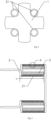
- the present disclosure provides a heating core for hot air gun use, comprising a mount support 1 and a heating wire arranged on the mount support 1, the mount support 1 being a ceramic mount support.
- the ceramic mount support may not only well concentrate the heat provided by the heating wire, but also may accumulate heat so as to well promote the heating effect of the entire heating core.
- the heating wire 2 comprises a close wound segment 21, where an interval between neighboring heating wires in the close wound segment 21 is D, 0 ⁇ D ⁇ 2mm.
- the heating wires are locally densified to increase the heating capacity of the heating wires at a local space and increase the heating density of the local space, which greatly raises the air-out temperature, thereby guaranteeing the working effect of the hot air gun; besides, it is not needed to increase the amount of heating wires, which facilitates reduction of energy consumption and improves heating efficiency, and meanwhile enhances the working efficiency of the hot air gun.
- local heating capacity produced by the heating wire configured with the close wound segment is greater than that produced by the heating wires without configuring a close wound segment, because the heat capacity produced by the close wound segment is concentrated and not easily dispersed, which raises the temperature of the hot air blown out; while the heat capacity produced by the heating wire without configuring a close wound segment is not concentrated enough, which causes easy dispersion of the heat, thereby greatly decreasing the temperature of the hot air blown out. Further, because the heat is concentrated and not easily dispersed, the surface temperature of the hot air tube or housing will not be over high, which would otherwise scald the user, thereby enhancing the safety of using the hot air gun.
- An insulating layer is provided on a surface of the heating wire 2 in the close wound segment 21. Arrangement of the insulating layer may prevent short-circuit due to contact between heating wires in the close wound segment, which would otherwise burn down the heating wires, thereby guaranteeing normal working of the heating wire.
- the close wound segment 21 is in a hollow spiral shape, i.e., the close wound segment 21 is spirally wound by the heating wire 2, which facilitates winding and forming of the close wound segment with a high production efficiency; further, setting the close wound segment to be hollow facilitates the wind produced by the hot air device to carry away the heat in the close wound segment; without obstruction for the wind, the heat will not be dispersed, such that the heat and the air will be blown to a same direction, which greatly increases the temperature of the hot air blown out.
- the longitudinal section of the mount support 1 is in a cross shape, wherein four close wound segments 21 are provided and distributed at four inner angles of the mount support 1, wherein two close wound segments 21 are formed by a heating wire wound with a certain interval and mounted on the mount support side by side; the other two close wound segments 21 are formed by another heating wire 2 wound with a certain space and arranged relative to the preceding two close wound segments 21, thereby combining to form a heating core with four close wound segments, such that the respective close wound segments are spaced from each other, which will not affect working of respective close wound segments, but still guarantee concentration of the heat between respective close wound segments, such that the heat is not easily dispersed; in this way, it well guarantees sufficiency of the air-out temperature, thereby further guaranteeing the working effect of the hot air gun and improving the working efficiency of the hot air gun.
- the interval between neighboring heating wires in the close wound segment 21 is set to D, 0 ⁇ D ⁇ 1mm; in this embodiment, D is specifically 0, i.e., the neighboring heating wires are closely attached to each other, such that they will be closely contacted; in this way, the produced heat will be more concentrated and not easily dispersed, which guarantees the sufficient temperature of the blown hot wind, thereby guaranteeing the working effect of the hot air gun and improving the working efficiency of the hot air gun.
- the close wound segment 21 is arranged transversely along the central axis direction of the mount support 1; in this way, the close wound segment is maintained consistent with the air-out direction of the hot air gun, such that when the air is blown out, it completely goes through the close wound segment, i.e., the air is completely through the close wound segment, which guarantees that the air may completely carry away the heat in the close wound segment to thereby guarantee that the air blown out has a sufficient temperature, thereby guaranteeing the working effect of the hot air gun and improving the working efficiency of the hot air gun; meanwhile, it reduces space occupation on the mount support by the close wound segment, causing the structure of the heating core more compact; further, a space for the hot air tube is reserved, which increases the air-out volume of the hot air tube, further improving the air discharging efficiency and working efficiency of the hot air gun.
- the axial length of the close wound segment 21 is L
- the diameter of the heating wire 2 is d, L being set between 2d and 30d.
- L is specifically 12d.
- an insulating heat concentrating element 3 is provided inside a hollow cavity of the close wound segment 21, such that heat produced by the heating wire may be better concentrated and not easily dispersed; in this way, when the air is blown out, it not only absorbs the temperature of the heating wire, but also absorbs the temperature of the heat concentrating element, which better guarantees the temperature of the hot air blown out; meanwhile, insulativity of the concentrating element prevents the heat concentrating element from contacting with the heating wire, which would otherwise cause the heating wire to be short-circuited, thereby guaranteeing normal working of the heating wire.
- the heat concentrating element 21 is a ceramic tube, which not only guarantees a good heat concentration, but also maintains a good insulativity; besides, it is endurable, wear-resistant, and has a long service life.
- the insulating layer is specifically a rare earth coating applied to the surface of the heating wire 1, which facilitates processing of the insulating layer; in this way, it not only guarantees the insulativity between heating wires in the close wound segment, but also facilitates forming of the close wound segment, thereby enhancing the production efficiency of the close wound segment.
- the close wound segment 21 is arranged proximal to an air outlet of the hot air gun, specifically at a front end of the mount support and proximal to the air outlet, such that when the heating wire is producing heat, the wind produced by the hot air device of the hot gun may directly carry the heat away to form hot air, and the hot air formed in this way is directly blown out from the air outlet and directly blown to a to-be-heated object to perform a corresponding work, which shortens the blow-out path of the hot air and avoids loss of part of the heat due to the long path of blowing out the hot air, i.e., reducing the loss of the hot air inside the hot air tube, thereby guaranteeing the temperature of the hot air blown out, further guaranteeing the working effect of the hot air gun and improving the working efficiency of the hot air gun.
- mount support may also be a mica mount support.
- D may also be 0.1mm, 0.2mm, 0.3mm, 0.4mm, 0.5mm, 0.6mm, 0.7mm, 0.8mm, 0.9mm, 1mm, 1.1mm, 1.2mm, 1.3mm, 1.4mm, 1.5mm, 1.6mm, 1.7mm, 1.8mm, 1.9mm, 2mm, etc.
- This setting may also cause the produced heat more concentrated and nor easily dispersed, which guarantees the sufficient temperature of the blown hot wind, thereby guaranteeing the working effect of the hot air gun and improving the working efficiency of the hot air gun.
- the close wound segment may also be arranged longitudinally, i.e., the central axis of the close wound segment is arranged non-coplanarly perpendicular to the central axis of the mount support, which may also achieve an effect of raising the air-out temperature.
- L can also be 2d, 3d, 4d, 5d, 6d, 7d, 8d, 9d, 10d, 11d, 13d, 14d, 15d, 16d, 17d, 18d, 19d, 20d, 21d, 22d, 23d, 24d, 25d, 26d, 27d, 28d, 29d, 30d, etc.
- the heat concentrating element may also be a ceramic column, a through-hole for air to pass through being provided at a center of the ceramic column, which reduces the resistance for air out, increases the contact area between the air and the heat concentrating element, and well increases the air-out temperature.
- the insulating layer may also be a rare earth bushing cladding the surface of the heating wire.
- the close wound segment may also be in a lump shape, i.e., the close wound segment is formed by cross winding of the heating wire; of course, it may also be wound into other shapes, such as a spherical shape, a square shape, a bar shape, a column shape, a triangular shape, etc.; the close wound segment may also be in a coil shape.
- the coil shape means that it is formed by spirally winding of the heating wire; the wound coil is in a ring shape with an inner hole. Such formed coil is relatively orderly organized with a pleasant appearance. It may also be formed by cross winding of the heating wire, such that the heating wires are crisscrossed to form a ring-shaped coil. Such formed coil is relatively messy, but has a higher local density and a higher heat capacity.
- the longitudinal section of the mount support may also be formed into a " " shape or shape.
- the numbers of close wound segments are 5 and 8, respectively; in this way, working of respective close wound segments will not be affected, and concentration of the heat between respective close wound segments is still guaranteed, such that the heat is not easily dispersed; as a result, the air-out temperature is guaranteed, thereby further guaranteeing the working effect of the hot air gun and improving the working efficiency of the hot air gun.
- the heating wires may also be provided in two, three, four, or five, etc.; and a plurality of heating wires are arranged side by side, such that when winding the close wound segment, e.g., in the case of 4 heating wires, one winding will result in the axial length of winding one heating wire for four windings, thereby enhancing the production efficiency of the close wound segment.
- Such a close wound segment has a more concentrated heat, which is less easily dispersed.
- the specific number of heating wires may be determined based on the specific structure of the heating gun and the user needs.
- the close wound segment may also be formed by a plurality of close wound segments with intervals.
- it is formed by close wound segments with the axial lengths L being 2d, 3d, 4d, 5d, 6d, 7d, 8d, 9d, or 10d, etc.
- the axial lengths of the plurality of close wound lengths arranged with intervals may also be different, e.g., the first close wound segment is 2d, the second close wound segment is 3d, the third close wound segment is 4d, so on and so forth; or it may also be the case that the first close wound segment is 5d, the second close wound segment is 3d, and the third close wound segment is 2d, etc. That is, the axial lengths may be decreasing or incremental, or may alternate between decrease and increment, or may even be arranged randomly, dependent on specific situations, which will not be detailed here.
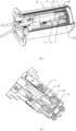
- the present disclosure further provides a hot air gun, comprising: a housing 4 in which a hot air device producing hot air is provided, the hot air device comprising a heating core; a hot air tube 5 provided at a front end of the housing, inside the hot air tube 5 being disposed the heating core, wherein the heating core is the heating core for hot air gun use in any technical solution above.
- a hot air gun comprising: a housing 4 in which a hot air device producing hot air is provided, the hot air device comprising a heating core; a hot air tube 5 provided at a front end of the housing, inside the hot air tube 5 being disposed the heating core, wherein the heating core is the heating core for hot air gun use in any technical solution above.
- the hot air gun comprises a battery pack 9 that is electrically connected with the hot air device to supply power to the hot air device to actuate the hot air device to work.
- the hot air gun is simpler and more convenient to use; when working, the hot air gun will not be limited by the power cord, such that it may be manipulated in any direction; besides, without the limit of power cord length during working, the hot air gun may be conveniently carried to any working environment without worrying about the operation range issue, which may well avoid a dilemma that the work cannot be done in case of failing to find a receptacle when working outdoors; therefore, it may be well adapted to outdoor work, which greatly expands the application scope of the hot air gun and promotes the use convenience thereof; further, the battery pack has limited power capacity and the power produced is also limited; however, when the heating core in any technical solution above is adopted, because this heating core has little loss but a large heating capacity, the durability of the battery pack is well improved, i.e., the working duration of the hot air gun is prolonged,
- an outer mica sleeve 6 and a ceramic sleeve 7 are provided in the hot air tube 5 to isolate the heating core from the hot air tube, wherein the ceramic sleeve 7 is arranged outside of the mount support 1 in a sleeved manner, the outer mica sleeve 6 is arranged outside of the ceramic sleeve 7 in a sleeved manner, and the hot air tube 5 is arranged on the outer mica sleeve 6 in a sleeved manner.
- the heat generated by the close wound segment is exactly further concentrated by the inner mica sleeve such that it is not easily dispersed, while by arranging the outer ceramic sleeve outside of the ceramic sleeve in a sleeved manner and arranging the hot air tube on the outer mica sleeve in a sleeved manner, the heat from the ceramic sleeve is further concentrated, preventing the heat on the ceramic sleeve from being dispersed and meanwhile further preventing heat from being transferred to the hot air tube, which may avoid the risk of scalding the user in case of accidentally touching the hot air tube.
- an inner mica sleeve 8 is provided in the hot air tube 5, wherein the inner mica sleeve 8 is arranged at a front end of the mount support 1 in a sleeved mode to clad the close wound segment 21, such that the heat generated by the close wound segment is exactly further concentrated by the inner mica sleeve such that it is not easily dispersed, which guarantees concentration and sufficiency of the heat produced by the close wound segment as well as the sufficiency of the air-out temperature, thereby further guaranteeing the working effect of the hot air gun and improving the working efficiency of the hot air gun.
- a ceramic air-out mesh 10 is provided inside the front end of the hot air tube 5, air-out mesh openings 101 being provided on the ceramic air-out mesh 10, the air-out mesh openings 101 being distributed in a honeycomb shape; in this way, the air blown out of the hot air gun has a uniform temperature, which will not cause a locally over high temperature, thereby guaranteeing the working effect and working stability of the hot air gun; further, the ceramic air-out mesh not only endures high temperature and resists against corrosion, but also may dissipate heat quickly when the hot air gun ends its work; therefore, it may well avoid scalding a human body, which enhances the safety of the hot air gun after use.
- the hot air gun may also be connected to alternating current through a power cord, the power cord being electrically connected to the hot air device to supply power to the hot air device so as to actuate the how wind device to word.
- the alternating current supplies power stably, which may guarantee that the hot air gun heats stably with sufficient wind power during use, such that work interruption will not easily occur due to instable voltage or current. In this way, the hot air gun may work continuously and stably indoors, and it will not occur that the work suspends due to insufficient battery level, thereby guaranteeing the working duration and working effect of the hot air gun.
- This embodiment differs from Embodiment I in the structure of the mount support.
- the longitudinal section of the mount support is formed into a Y shape.
- three close wound segments 21 are provided and distributed at three inner angles of the mount support 1, such that the respective close wound segments can be likewise spaced from each other, which will not affect working of respective close wound segments, but still guarantee concentration of the heat between respective close wound segments, such that the heat is not easily dispersed; in this way, it well guarantees sufficient air-out temperature, thereby further guaranteeing the working effect of the hot air gun and improving the working efficiency of the hot air gun.
- This embodiment differs from Embodiment I in the structure of the mount support.
- the longitudinal section of the mount support is formed into a " " shape.
- six close wound segments 21 are provided and distributed at six inner angles of the mount support 1, such that the respective close wound segments can be likewise spaced from each other, which will not affect working of respective close wound segments, but still guarantee concentration of the heat between respective close wound segments, such that the heat is not easily dispersed; in this way, it well guarantees sufficient air-out temperature, thereby further guaranteeing the working effect of the hot air gun and improving the working efficiency of the hot air gun.
Landscapes
- Engineering & Computer Science (AREA)
- Mechanical Engineering (AREA)
- Physics & Mathematics (AREA)
- Thermal Sciences (AREA)
- Chemical & Material Sciences (AREA)
- Combustion & Propulsion (AREA)
- General Engineering & Computer Science (AREA)
- Direct Air Heating By Heater Or Combustion Gas (AREA)
- Resistance Heating (AREA)
Claims (12)
- Heizkern für eine Heißluftpistole, der Heizkern umfassend:einen Montageträger (1); undeinen Heizdraht (2), der auf dem Montageträger (1) angeordnet ist; wobeider Heizdraht (2) ein dicht gewickeltes Segment (21) aufweist, auf dessen Oberfläche eine Isolierschicht bereitgestellt ist,wobeiein Abstand zwischen angrenzenden Heizdrähten in dem dicht gewickelten Segment (21) D beträgt, 0≤D≤2 mm, undein Längsabschnitt des Montageträgers in einer Kreuzform ist, wobei vier dicht gewickelte Segmente bereitgestellt und an vier Innenwinkeln des Montageträgers (1) verteilt sind; oder,der Längsabschnitt des Montageträgers in einer Y-Form ist, wobei drei dicht gewickelte Segmente bereitgestellt und an drei Innenwinkeln des Montageträgers (1) verteilt sind; oder,der Längsschnitt des Montageträgers in einer ""-Form ist, wobei fünf dicht gewickelte Segmente bereitgestellt und an fünf Innenwinkeln des Montageträgers (1) verteilt sind; oder,
 der Längsschnitt des Montageträgers in einer ""-Form ist, wobei sechs dicht gewickelte Segmente bereitgestellt und an sechs Innenwinkeln des Montageträgers (1) verteilt sind; oder,
 der Längsschnitt des Montageträgers in einer ""-Form ist, wobei acht dicht gewickelte Segmente bereitgestellt und an acht Innenwinkeln des Montageträgers (1) verteilt sind
 dadurch gekennzeichnet, dassein isolierendes Hitzekonzentrationselement (3) innerhalb eines Hohlraums des dicht gewickelten Segments (21) angeordnet ist.
 - Heizkern zur Verwendung mit einer Heizpistole nach Anspruch 1, wobei:
das dicht gewickelte Segment (21) eine hohle Spiralform aufweist, und ein Abstand zwischen angrenzenden Heizdrähten in dem dicht gewickelten Segment (21) D beträgt, 0≤D≤1 mm. - Heizkern zur Verwendung mit einer Heizpistole nach Anspruch 2, wobei eine axiale Länge des dicht gewickelten Segments (21) L beträgt und ein Durchmesser des Heizdrahtes (2) d beträgt, 2d≤L≤30d.
- Heizkern zur Verwendung mit einer Heizpistole nach Anspruch 1, wobei das Hitzekonzentrationselement (3) ein Keramikrohr oder eine Keramiksäule ist.
- Heizkern zur Verwendung mit einer Heizpistole nach Anspruch 1, wobei die Isolierschicht eine Seltenerdenbeschichtung ist, die auf die Oberfläche des Heizdrahtes (2) aufgebracht ist; oder die Isolierschicht eine Seltenerdenmuffe ist, die die Oberfläche des Heizdrahtes (2) umhüllt.
- Heizkern zur Verwendung mit einer Heizpistole nach Anspruch 1, wobei das dicht gewickelte Segment (21) zu einem Luftauslass der Heißluftpistole proximal angeordnet ist.
- Heizkern zur Verwendung mit einer Heizpistole nach Anspruch 1, wobei das dicht gewickelte Segment (21) in einer Spulenform ist.
- Heißluftpistole, umfassend:ein Gehäuse (4), in dem eine Heißluftvorrichtung, die Heißluft produziert, bereitgestellt ist, die Heißluftvorrichtung umfassend einen Heizkern nach einem der Ansprüche 1 bis 7; undein Heißluftrohr (5), das an einem vorderen Ende des Gehäuses bereitgestellt ist, wobei innerhalb des Heißluftrohrs (5) der Heizkern angeordnet ist.
- Heißpistole nach Anspruch 8, wobei:
eine äußere Glimmerhülse (6) und eine Keramikhülse (7) in dem Heißluftrohr bereitgestellt sind, um den Heizkern von dem Heißluftrohr (5) zu isolieren, wobei:die Keramikhülse (7) außerhalb des Montageträgers hülsenartig angeordnet ist,die äußere Glimmerhülse (6) außerhalb der Keramikhülse (7) hülsenartig angeordnet ist, unddas Heißluftrohr auf der äußeren Glimmerhülse (6) hülsenartig angeordnet ist. - Heißpistole nach Anspruch 9, wobei eine innere Glimmerhülse in dem Heißluftrohr bereitgestellt ist, wobei die innere Glimmerhülse an einem vorderen Ende des Montageträgers in einem Hülsenmodus angeordnet ist, um das dicht gewickelte Segment zu umhüllen.
- Heißpistole nach Anspruch 8, wobei:die Heißluftpistole einen Batteriesatz (9) umfasst, wobei der Batteriesatz (9) mit der Heißluftvorrichtung elektrisch verbunden ist und die Heißluftvorrichtung mit Leistung versorgt, um die Heißluftvorrichtung zu betätigen, um zu arbeiten; oder,die Heißluftpistole ein Netzkabel umfasst, wobei ein Ende des Netzkabels an Wechselstrom angeschlossen ist und das andere Ende mit der Heißluftvorrichtung elektrisch verbunden ist, um die Heißluftvorrichtung mit Leistung zu versorgen, um die Heißluftvorrichtung zu betätigen, um zu arbeiten.
- Heißpistole nach Anspruch 8, wobei ein keramisches Luftauslassgitter innerhalb des vorderen Endes des Heißluftrohrs bereitgestellt ist, wobei Luftauslassgitteröffnungen auf dem keramischen Luftauslassgitter bereitgestellt sind, wobei die Luftauslassgitteröffnungen wabenförmig verteilt sind.
Applications Claiming Priority (1)
| Application Number | Priority Date | Filing Date | Title |
|---|---|---|---|
| CN201810313098.4A CN108826671A (zh) | 2018-04-09 | 2018-04-09 | 一种热风枪用发热芯及热风枪 |
Publications (3)
| Publication Number | Publication Date |
|---|---|
| EP3553411A1 EP3553411A1 (de) | 2019-10-16 |
| EP3553411C0 EP3553411C0 (de) | 2025-01-22 |
| EP3553411B1 true EP3553411B1 (de) | 2025-01-22 |
Family
ID=62631028
Family Applications (1)
| Application Number | Title | Priority Date | Filing Date |
|---|---|---|---|
| EP18177576.8A Active EP3553411B1 (de) | 2018-04-09 | 2018-06-13 | Heizkern für heissluftpistole und heissluftpistole |
Country Status (4)
| Country | Link |
|---|---|
| US (1) | US11530843B2 (de) |
| EP (1) | EP3553411B1 (de) |
| JP (1) | JP6786552B2 (de) |
| CN (1) | CN108826671A (de) |
Families Citing this family (9)
| Publication number | Priority date | Publication date | Assignee | Title |
|---|---|---|---|---|
| CN110145866B (zh) * | 2019-06-12 | 2023-12-15 | 常州武进长城工具有限公司 | 热风枪 |
| DE102019126211A1 (de) * | 2019-09-27 | 2021-04-01 | Steinel Gmbh | Heißluftgebläse und Heizmittelträger für ein Heißluftgebläse |
| DE102019126217A1 (de) * | 2019-09-27 | 2021-04-01 | Steinel Gmbh | Heißluftgebläse und Heizmittel für ein Heißluftgebläse |
| USD947631S1 (en) * | 2019-12-26 | 2022-04-05 | Zhejiang Prulde Electric Appliance Co., Ltd. | Heat gun |
| WO2022129551A1 (de) * | 2020-12-18 | 2022-06-23 | Steinel Gmbh | HEIßLUFTGEBLÄSE |
| JP1710804S (ja) * | 2021-06-10 | 2022-03-25 | ヒートガン本体 | |
| CN113566418B (zh) * | 2021-06-11 | 2023-04-07 | 浙江普莱得电器股份有限公司 | 一种带有导流件的热风枪 |
| JP1705427S (ja) * | 2021-07-09 | 2022-01-19 | エアダスター本体 | |
| USD1032313S1 (en) | 2022-09-19 | 2024-06-25 | Steinel Gmbh | Hot air gun |
Family Cites Families (22)
| Publication number | Priority date | Publication date | Assignee | Title |
|---|---|---|---|---|
| US2042264A (en) * | 1935-02-12 | 1936-05-26 | Alexander F Levenhagen | Hot air gun |
| US3492462A (en) * | 1966-10-03 | 1970-01-27 | Fred E Schumacher | Heat gun |
| JPS5440755A (en) * | 1977-09-07 | 1979-03-30 | Hitachi Ltd | Hair dryer |
| GB8334366D0 (en) * | 1983-12-23 | 1984-02-01 | Black & Decker Inc | Hot air gun |
| GB8415637D0 (en) * | 1984-06-19 | 1984-07-25 | Black & Decker Inc | Supports for electric heating elements |
| DE3903961A1 (de) * | 1989-02-10 | 1990-08-16 | Wuerth Friedrich Fa | Heizelement |
| CN2113584U (zh) * | 1990-10-22 | 1992-08-19 | 姚德利 | 高温自绝缘电热芯 |
| JP2004105577A (ja) * | 2002-09-20 | 2004-04-08 | Msa Kk | ツヤとしっとりさが出る風を吹き出すヘアードライヤー |
| US8435459B2 (en) * | 2003-01-07 | 2013-05-07 | Micropyretics Heaters International, Inc. | Heating and sterilizing apparatus and method of using same |
| JP3785422B2 (ja) * | 2004-09-14 | 2006-06-14 | 株式会社万雄 | 温風加熱器 |
| US7717104B2 (en) * | 2005-07-12 | 2010-05-18 | Looft Industries Ab | Handheld device for fast electrical ignition of a charcoal grill |
| EP1836919B1 (de) * | 2006-03-23 | 2009-01-21 | Vertex Precision Electronics Inc. | Haartrockner mit einer wärmeerzeugenden Vorrichtung |
| CN200979286Y (zh) * | 2006-11-24 | 2007-11-21 | 丁兆兰 | 热风枪风管 |
| GB2446412A (en) * | 2007-02-09 | 2008-08-13 | Duna Entpr Sa | Heating structure for hair dryers |
| CN201522108U (zh) * | 2009-09-30 | 2010-07-07 | 黄德超 | 一种热风枪直列式发热芯 |
| CN103148589A (zh) | 2013-03-08 | 2013-06-12 | 浙江普莱得电器有限公司 | 一种热风枪用发热芯 |
| CN203231552U (zh) | 2013-03-29 | 2013-10-09 | 浙江普莱得电器有限公司 | 热风枪用发热芯组件 |
| WO2015052737A1 (en) * | 2013-10-11 | 2015-04-16 | Gamma S.P.A. | Method of manufacturing a coaxial electric resistance and coaxial electric resistance |
| US20190090607A1 (en) * | 2015-06-26 | 2019-03-28 | HOSPISTYLE di Trapani Maria | Hairdryer with high electrical safety |
| CN107014072A (zh) * | 2017-04-18 | 2017-08-04 | 吴俊� | 一种自动控温式智能热风枪 |
| CN107655206B (zh) * | 2017-08-21 | 2020-09-15 | 浙江普莱得电器有限公司 | 一种可检测温度的热风枪 |
| CN207100839U (zh) * | 2017-08-31 | 2018-03-16 | 江门市润生机电有限公司 | 一种低耗高输出的吹风机 |
-
2018
- 2018-04-09 CN CN201810313098.4A patent/CN108826671A/zh active Pending
- 2018-06-13 EP EP18177576.8A patent/EP3553411B1/de active Active
- 2018-06-20 JP JP2018117007A patent/JP6786552B2/ja active Active
- 2018-07-20 US US16/041,654 patent/US11530843B2/en active Active
Also Published As
| Publication number | Publication date |
|---|---|
| US20190309988A1 (en) | 2019-10-10 |
| EP3553411C0 (de) | 2025-01-22 |
| JP2019186182A (ja) | 2019-10-24 |
| EP3553411A1 (de) | 2019-10-16 |
| US11530843B2 (en) | 2022-12-20 |
| JP6786552B2 (ja) | 2020-11-18 |
| CN108826671A (zh) | 2018-11-16 |
Similar Documents
| Publication | Publication Date | Title |
|---|---|---|
| EP3553411B1 (de) | Heizkern für heissluftpistole und heissluftpistole | |
| US9532599B2 (en) | Electronic cigarette | |
| US9955731B2 (en) | Atomizer and electronic cigarette with cylindrical pressed-wire heating element | |
| EP4494500A1 (de) | Heizkörper und zerstäubungsvorrichtung für heizung | |
| JP2019517840A (ja) | 電子ベイピング装置 | |
| CN101226818B (zh) | 绕组组件 | |
| CN211832820U (zh) | 一种电子雾化装置及其加热组件和发热结构 | |
| KR102091470B1 (ko) | 세라믹 히터 유닛을 구비한 헤어 드라이어 | |
| CN208238245U (zh) | 一种发热效果好的热风枪用发热芯及热风枪 | |
| CN217791481U (zh) | 加热组件及加热雾化装置 | |
| CN210930056U (zh) | 一种电吹风 | |
| KR100625859B1 (ko) | 전기로 | |
| CN215337129U (zh) | 热风枪的发热芯结构 | |
| CN216059226U (zh) | 一种雾化装置及其发热组件 | |
| CN217851362U (zh) | 一种螺旋状发热元件 | |
| KR20110121843A (ko) | 탄소섬유 발열선을 이용한 원적외선 히터 | |
| CN219494419U (zh) | 热风枪的发热芯结构及其热风枪 | |
| JP4233058B1 (ja) | 放電電極 | |
| JPH0728713Y2 (ja) | 送風気体加熱用ヒーターの発熱体の改良 | |
| CN111838934A (zh) | 一种平面加热无绳电吹风 | |
| CN217986694U (zh) | 一种陶瓷发热芯、雾化器及电子烟 | |
| CN223262367U (zh) | 一种发热网片、发热组件、雾化芯以及气溶胶产生装置 | |
| KR200306865Y1 (ko) | 파마 셋팅기용 로드 | |
| CN223873277U (zh) | 治具棒及雾化结构 | |
| CN102319935B (zh) | 一种外热型烙铁芯结构 |
Legal Events
| Date | Code | Title | Description |
|---|---|---|---|
| PUAI | Public reference made under article 153(3) epc to a published international application that has entered the european phase |
Free format text: ORIGINAL CODE: 0009012 |
|
| STAA | Information on the status of an ep patent application or granted ep patent |
Free format text: STATUS: THE APPLICATION HAS BEEN PUBLISHED |
|
| AK | Designated contracting states |
Kind code of ref document: A1 Designated state(s): AL AT BE BG CH CY CZ DE DK EE ES FI FR GB GR HR HU IE IS IT LI LT LU LV MC MK MT NL NO PL PT RO RS SE SI SK SM TR |
|
| AX | Request for extension of the european patent |
Extension state: BA ME |
|
| STAA | Information on the status of an ep patent application or granted ep patent |
Free format text: STATUS: REQUEST FOR EXAMINATION WAS MADE |
|
| 17P | Request for examination filed |
Effective date: 20200416 |
|
| RBV | Designated contracting states (corrected) |
Designated state(s): AL AT BE BG CH CY CZ DE DK EE ES FI FR GB GR HR HU IE IS IT LI LT LU LV MC MK MT NL NO PL PT RO RS SE SI SK SM TR |
|
| STAA | Information on the status of an ep patent application or granted ep patent |
Free format text: STATUS: EXAMINATION IS IN PROGRESS |
|
| 17Q | First examination report despatched |
Effective date: 20240328 |
|
| GRAP | Despatch of communication of intention to grant a patent |
Free format text: ORIGINAL CODE: EPIDOSNIGR1 |
|
| STAA | Information on the status of an ep patent application or granted ep patent |
Free format text: STATUS: GRANT OF PATENT IS INTENDED |
|
| INTG | Intention to grant announced |
Effective date: 20241010 |
|
| GRAS | Grant fee paid |
Free format text: ORIGINAL CODE: EPIDOSNIGR3 |
|
| GRAA | (expected) grant |
Free format text: ORIGINAL CODE: 0009210 |
|
| STAA | Information on the status of an ep patent application or granted ep patent |
Free format text: STATUS: THE PATENT HAS BEEN GRANTED |
|
| AK | Designated contracting states |
Kind code of ref document: B1 Designated state(s): AL AT BE BG CH CY CZ DE DK EE ES FI FR GB GR HR HU IE IS IT LI LT LU LV MC MK MT NL NO PL PT RO RS SE SI SK SM TR |
|
| REG | Reference to a national code |
Ref country code: GB Ref legal event code: FG4D |
|
| REG | Reference to a national code |
Ref country code: CH Ref legal event code: EP |
|
| REG | Reference to a national code |
Ref country code: IE Ref legal event code: FG4D |
|
| REG | Reference to a national code |
Ref country code: DE Ref legal event code: R096 Ref document number: 602018078631 Country of ref document: DE |
|
| U01 | Request for unitary effect filed |
Effective date: 20250221 |
|
| U07 | Unitary effect registered |
Designated state(s): AT BE BG DE DK EE FI FR IT LT LU LV MT NL PT RO SE SI Effective date: 20250314 |
|
| U20 | Renewal fee for the european patent with unitary effect paid |
Year of fee payment: 8 Effective date: 20250528 |
|
| PG25 | Lapsed in a contracting state [announced via postgrant information from national office to epo] |
Ref country code: RS Free format text: LAPSE BECAUSE OF FAILURE TO SUBMIT A TRANSLATION OF THE DESCRIPTION OR TO PAY THE FEE WITHIN THE PRESCRIBED TIME-LIMIT Effective date: 20250422 |
|
| PG25 | Lapsed in a contracting state [announced via postgrant information from national office to epo] |
Ref country code: PL Free format text: LAPSE BECAUSE OF FAILURE TO SUBMIT A TRANSLATION OF THE DESCRIPTION OR TO PAY THE FEE WITHIN THE PRESCRIBED TIME-LIMIT Effective date: 20250122 |
|
| PG25 | Lapsed in a contracting state [announced via postgrant information from national office to epo] |
Ref country code: ES Free format text: LAPSE BECAUSE OF FAILURE TO SUBMIT A TRANSLATION OF THE DESCRIPTION OR TO PAY THE FEE WITHIN THE PRESCRIBED TIME-LIMIT Effective date: 20250122 |
|
| PGFP | Annual fee paid to national office [announced via postgrant information from national office to epo] |
Ref country code: GB Payment date: 20250625 Year of fee payment: 8 |
|
| PG25 | Lapsed in a contracting state [announced via postgrant information from national office to epo] |
Ref country code: IS Free format text: LAPSE BECAUSE OF FAILURE TO SUBMIT A TRANSLATION OF THE DESCRIPTION OR TO PAY THE FEE WITHIN THE PRESCRIBED TIME-LIMIT Effective date: 20250522 Ref country code: NO Free format text: LAPSE BECAUSE OF FAILURE TO SUBMIT A TRANSLATION OF THE DESCRIPTION OR TO PAY THE FEE WITHIN THE PRESCRIBED TIME-LIMIT Effective date: 20250422 |
|
| PG25 | Lapsed in a contracting state [announced via postgrant information from national office to epo] |
Ref country code: HR Free format text: LAPSE BECAUSE OF FAILURE TO SUBMIT A TRANSLATION OF THE DESCRIPTION OR TO PAY THE FEE WITHIN THE PRESCRIBED TIME-LIMIT Effective date: 20250122 |
|
| PG25 | Lapsed in a contracting state [announced via postgrant information from national office to epo] |
Ref country code: GR Free format text: LAPSE BECAUSE OF FAILURE TO SUBMIT A TRANSLATION OF THE DESCRIPTION OR TO PAY THE FEE WITHIN THE PRESCRIBED TIME-LIMIT Effective date: 20250423 |
|
| PG25 | Lapsed in a contracting state [announced via postgrant information from national office to epo] |
Ref country code: SM Free format text: LAPSE BECAUSE OF FAILURE TO SUBMIT A TRANSLATION OF THE DESCRIPTION OR TO PAY THE FEE WITHIN THE PRESCRIBED TIME-LIMIT Effective date: 20250122 |
|
| PG25 | Lapsed in a contracting state [announced via postgrant information from national office to epo] |
Ref country code: CZ Free format text: LAPSE BECAUSE OF FAILURE TO SUBMIT A TRANSLATION OF THE DESCRIPTION OR TO PAY THE FEE WITHIN THE PRESCRIBED TIME-LIMIT Effective date: 20250122 |
|
| PG25 | Lapsed in a contracting state [announced via postgrant information from national office to epo] |
Ref country code: SK Free format text: LAPSE BECAUSE OF FAILURE TO SUBMIT A TRANSLATION OF THE DESCRIPTION OR TO PAY THE FEE WITHIN THE PRESCRIBED TIME-LIMIT Effective date: 20250122 |
|
| PLBE | No opposition filed within time limit |
Free format text: ORIGINAL CODE: 0009261 |
|
| STAA | Information on the status of an ep patent application or granted ep patent |
Free format text: STATUS: NO OPPOSITION FILED WITHIN TIME LIMIT |
|
| REG | Reference to a national code |
Ref country code: CH Ref legal event code: L10 Free format text: ST27 STATUS EVENT CODE: U-0-0-L10-L00 (AS PROVIDED BY THE NATIONAL OFFICE) Effective date: 20251203 |
|
| 26N | No opposition filed |
Effective date: 20251023 |
|
| REG | Reference to a national code |
Ref country code: CH Ref legal event code: H13 Free format text: ST27 STATUS EVENT CODE: U-0-0-H10-H13 (AS PROVIDED BY THE NATIONAL OFFICE) Effective date: 20260127 |
|
| PG25 | Lapsed in a contracting state [announced via postgrant information from national office to epo] |
Ref country code: MC Free format text: LAPSE BECAUSE OF FAILURE TO SUBMIT A TRANSLATION OF THE DESCRIPTION OR TO PAY THE FEE WITHIN THE PRESCRIBED TIME-LIMIT Effective date: 20250122 |
|
| PG25 | Lapsed in a contracting state [announced via postgrant information from national office to epo] |
Ref country code: IE Free format text: LAPSE BECAUSE OF NON-PAYMENT OF DUE FEES Effective date: 20250613 |