EP3553335B1 - Mediumsversorgungssystem - Google Patents
Mediumsversorgungssystem Download PDFInfo
- Publication number
- EP3553335B1 EP3553335B1 EP19000161.0A EP19000161A EP3553335B1 EP 3553335 B1 EP3553335 B1 EP 3553335B1 EP 19000161 A EP19000161 A EP 19000161A EP 3553335 B1 EP3553335 B1 EP 3553335B1
- Authority
- EP
- European Patent Office
- Prior art keywords
- medium
- valve
- hollow profile
- supply system
- profile
- Prior art date
- Legal status (The legal status is an assumption and is not a legal conclusion. Google has not performed a legal analysis and makes no representation as to the accuracy of the status listed.)
- Active
Links
Images


Classifications
-
- F—MECHANICAL ENGINEERING; LIGHTING; HEATING; WEAPONS; BLASTING
- F16—ENGINEERING ELEMENTS AND UNITS; GENERAL MEASURES FOR PRODUCING AND MAINTAINING EFFECTIVE FUNCTIONING OF MACHINES OR INSTALLATIONS; THERMAL INSULATION IN GENERAL
- F16C—SHAFTS; FLEXIBLE SHAFTS; ELEMENTS OR CRANKSHAFT MECHANISMS; ROTARY BODIES OTHER THAN GEARING ELEMENTS; BEARINGS
- F16C29/00—Bearings for parts moving only linearly
- F16C29/004—Fixing of a carriage or rail, e.g. rigid mounting to a support structure or a movable part
-
- F—MECHANICAL ENGINEERING; LIGHTING; HEATING; WEAPONS; BLASTING
- F16—ENGINEERING ELEMENTS AND UNITS; GENERAL MEASURES FOR PRODUCING AND MAINTAINING EFFECTIVE FUNCTIONING OF MACHINES OR INSTALLATIONS; THERMAL INSULATION IN GENERAL
- F16C—SHAFTS; FLEXIBLE SHAFTS; ELEMENTS OR CRANKSHAFT MECHANISMS; ROTARY BODIES OTHER THAN GEARING ELEMENTS; BEARINGS
- F16C29/00—Bearings for parts moving only linearly
- F16C29/005—Guide rails or tracks for a linear bearing, i.e. adapted for movement of a carriage or bearing body there along
-
- F—MECHANICAL ENGINEERING; LIGHTING; HEATING; WEAPONS; BLASTING
- F16—ENGINEERING ELEMENTS AND UNITS; GENERAL MEASURES FOR PRODUCING AND MAINTAINING EFFECTIVE FUNCTIONING OF MACHINES OR INSTALLATIONS; THERMAL INSULATION IN GENERAL
- F16C—SHAFTS; FLEXIBLE SHAFTS; ELEMENTS OR CRANKSHAFT MECHANISMS; ROTARY BODIES OTHER THAN GEARING ELEMENTS; BEARINGS
- F16C29/00—Bearings for parts moving only linearly
- F16C29/02—Sliding-contact bearings
- F16C29/025—Hydrostatic or aerostatic
-
- F—MECHANICAL ENGINEERING; LIGHTING; HEATING; WEAPONS; BLASTING
- F16—ENGINEERING ELEMENTS AND UNITS; GENERAL MEASURES FOR PRODUCING AND MAINTAINING EFFECTIVE FUNCTIONING OF MACHINES OR INSTALLATIONS; THERMAL INSULATION IN GENERAL
- F16C—SHAFTS; FLEXIBLE SHAFTS; ELEMENTS OR CRANKSHAFT MECHANISMS; ROTARY BODIES OTHER THAN GEARING ELEMENTS; BEARINGS
- F16C29/00—Bearings for parts moving only linearly
- F16C29/08—Arrangements for covering or protecting the ways
- F16C29/082—Arrangements for covering or protecting the ways fixed to the way
-
- F—MECHANICAL ENGINEERING; LIGHTING; HEATING; WEAPONS; BLASTING
- F16—ENGINEERING ELEMENTS AND UNITS; GENERAL MEASURES FOR PRODUCING AND MAINTAINING EFFECTIVE FUNCTIONING OF MACHINES OR INSTALLATIONS; THERMAL INSULATION IN GENERAL
- F16C—SHAFTS; FLEXIBLE SHAFTS; ELEMENTS OR CRANKSHAFT MECHANISMS; ROTARY BODIES OTHER THAN GEARING ELEMENTS; BEARINGS
- F16C29/00—Bearings for parts moving only linearly
- F16C29/08—Arrangements for covering or protecting the ways
- F16C29/084—Arrangements for covering or protecting the ways fixed to the carriage or bearing body movable along the guide rail or track
-
- F—MECHANICAL ENGINEERING; LIGHTING; HEATING; WEAPONS; BLASTING
- F16—ENGINEERING ELEMENTS AND UNITS; GENERAL MEASURES FOR PRODUCING AND MAINTAINING EFFECTIVE FUNCTIONING OF MACHINES OR INSTALLATIONS; THERMAL INSULATION IN GENERAL
- F16C—SHAFTS; FLEXIBLE SHAFTS; ELEMENTS OR CRANKSHAFT MECHANISMS; ROTARY BODIES OTHER THAN GEARING ELEMENTS; BEARINGS
- F16C2326/00—Articles relating to transporting
- F16C2326/58—Conveyor systems, e.g. rollers or bearings therefor
-
- F—MECHANICAL ENGINEERING; LIGHTING; HEATING; WEAPONS; BLASTING
- F16—ENGINEERING ELEMENTS AND UNITS; GENERAL MEASURES FOR PRODUCING AND MAINTAINING EFFECTIVE FUNCTIONING OF MACHINES OR INSTALLATIONS; THERMAL INSULATION IN GENERAL
- F16C—SHAFTS; FLEXIBLE SHAFTS; ELEMENTS OR CRANKSHAFT MECHANISMS; ROTARY BODIES OTHER THAN GEARING ELEMENTS; BEARINGS
- F16C29/00—Bearings for parts moving only linearly
- F16C29/04—Ball or roller bearings
- F16C29/06—Ball or roller bearings in which the rolling bodies circulate partly without carrying load
- F16C29/068—Ball or roller bearings in which the rolling bodies circulate partly without carrying load with the bearing body fully encircling the guide rail or track
Definitions
- the invention relates to a medium supply system with at least one stationary mounted hollow profile carrying a gaseous or liquid medium and a rail-guided transport carriage equipped with a medium collector.
- the air supply is an elongated tube that has a longitudinal slit.
- the longitudinal slit is closed from the inside of the pipe with a valve membrane covering the longitudinal slit.
- a cam rests on the valve membrane inside the air tap, which lifts the valve membrane from the longitudinal slot so that compressed air passes out of the tube into the air tap.
- the EP 1 816 361 A1 describes two air-bearing compound slides of an apparatus for the production of patterns lithographically produced by means of an electron beam.
- Each slide of the individual compound slide has the shape of a square tube as a fixed bearing, which encloses a square-shaped guide rail.
- the square tube slide is supported against the guide rail by several air bearings.
- a large number of differential pressure-controlled pilot valves are located along the hollow, compressed air-carrying guide rail. The square tube carriage sliding along the guide rail draws the compressed air for its air bearings when passing over the pilot valves.
- the linear unit consists of a cylinder or a linear drive such as a motor and ball screw rod or threaded rod with nut element, an air rail arranged parallel to this, which runs along its entire length Contains tapping points that are arranged at short intervals and a compressed air collector that can be moved on suitable guide rails of the air rail.
- the present invention is based on the problem of creating a medium supply system for one or more rail-guided transport carriages for workpieces, with which the transport carriages can be supplied with a gaseous or liquid medium safely and without leakage over at least part of their route.
- a medium supply system is created with which, for example, rail-guided transport vehicles can be supplied with a gaseous or liquid medium without the individual transport vehicle having to pull a supply hose behind it.
- the transport wagon along the transport route, the transport wagon, at least in some areas, a hollow profile guiding the medium is arranged, along which the medium collector is guided.
- many valves are usually arranged one behind the other with smaller or larger distances in the hollow profile.
- the valves which are generally closed outside the medium consumer, form a transfer track.
- the distance between the valves arranged in the hollow profile and the length of the medium collector are designed in such a way that, adapted to the speed of the transport carriage driving over them, the valves have enough time to open, a sufficient medium volume - e.g. to maintain the printer - to hand over and close again.
- the transport trolley or the medium collector can also be equipped with a medium reservoir.
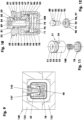
- the figure 2 shows a longitudinal section through the hollow profile (10) and the medium collector (130) of a medium supply system that enables a vacuum connection to a transport vehicle.
- the hollow profile (10) here is a continuous cast profile made from an aluminum alloy in the form of a square tube (11) which has an essentially square cross section. For example, with a cross-sectional edge length of 30 mm, it has a wall thickness that corresponds to a tenth to a quarter of this cross-sectional edge length.
- the longitudinal edges (12) of the square tube (11), cf. figure 1 are rounded with a radius of eg 4 mm.
- Two O-ring grooves (112) arranged next to one another are worked into the inner wall of the cap recess (111) between the threaded bore (116) and the base. O-rings (113) or comparable sealants are inserted in the O-ring grooves (112).
- the bridging cap (120) consists of a truncated pyramid area (121) and a seating area (122).
- the seating area (122) protrudes, for example, 20 mm into the interior (19) of the square tube (11), while the truncated pyramid area (121) represents a tapering extension of the square tube (11).
- the truncated pyramid area (121) has a base contour that corresponds to the outer circumferential edge of the square tube (11). With a pyramid apex angle of ten degrees, for example, it is 34.4 mm long. It tapers - starting from the foot contour - towards the free end of the transfer cap (120). A threaded hole is arranged in the face of the free end as a medium connection (125).
- the transfer cap (120) creates a hollow profile closure onto which the medium collectors (130) can drive. With the aid of the ramp-like outer contour of the transfer cap (120), the seals of the medium collector (130) are widened when driving on—without additional wear and too much effort, cf. Figures 13 to 15 .
- valve installation bores (13) are arranged one behind the other at equidistant intervals in a side wall of the square tube (11).
- all valve installation bores (13) have center lines that lie in one plane.
- the center line of the square tube (11) is also located in this plane.
- Suction valves (20) sit in the valve installation bores (13), their free end faces or end faces lie in the outer wall plane of the square tube (11), in which the valve installation bores (13) are incorporated.
- the hollow profile can also be a cylindrical tube, a rectangular tube or another polygonal tube.
- the hollow profile can be subdivided in the interior by one or more intermediate walls in the longitudinal direction of the hollow profile, so that media-carrying zones which are separated from one another arise.
- the individual suction valve (20) to be inserted into a valve installation bore (13) consists of a valve seat sleeve (21) and a vacuum valve member (30), cf. figure 4 .
- the essentially tubular valve seat sleeve (21) comprises a fastening area (22) and a guide area (23). With a length of 8.5 mm in the attachment area (22), for example, it has a diameter of 19 mm.
- the 3.2 mm wide attachment area (22) has a circumferential annular groove approximately in the middle, the depth of which measures 0.2 mm, for example.
- the recess of the valve seat sleeve (21) has a conical surface (27) as the inner wall in the fastening area (22), the largest diameter of which measures 17.85 mm and the apex angle of which encloses an angle of 60 degrees.
- the depth of the conical surface (27) corresponds to approximately 53% of the wall thickness of the square tube (11).
- a 0.7 mm deep cylinder countersink connects to the conical surface (27).
- the flat bottom surface of the cylinder countersinks serves as a seat sealing surface (28) for an O-ring (38) seated on the vacuum valve member (30).
- the seat sealing surface (28) is adjoined by a cylindrical through-bore which ends at the lower end of the guide area (23) in a planar holding face (24).
- the guide area (23) has an outer diameter of 18.3 mm, for example.
- the transition area between the guide area (23) and the attachment area (22) has the shape of a straight truncated cone whose cone angle is 40 degrees.
- the vacuum valve member (30) is shown in its open position. It sits in the recess (26) of the valve seat sleeve (21) with a radial play of, for example, 0.14 mm.
- the maximum opening stroke measures 3.1 mm.
- the vacuum valve member (30) consists of a valve disk (31), for example four guide elements (36) and a central magnetic holding sleeve (35), cf. figure 5 .
- the magnet holding sleeve (35) together with the four guide elements (36) is formed on the valve plate (31).
- the valve disk (31) is a flat disc with a wall thickness of 1.7 mm. Its flat underside forms the link sealing surface (33). It has an outer wall in the form of a conical centering surface (32) whose cone angle includes 60 degrees.
- the valve plate (31) is followed by a 1.1 mm thick cylindrical shoulder, which has a maximum diameter of 13.3 mm, for example. In the central area, the paragraph has a circumferential groove (34) in which an O-ring (38) is inserted.
- equidistantly divided guide elements for example 10.8 mm long, which end in rear grip hooks (37) in the region of their free end.
- the guide elements (36) rest against the recess (26) of the valve seat sleeve (21) with play.
- their rear gripping hooks (37) lie flat on the holding face (24) of the valve seat sleeve (21).
- the guide elements (36) include the central magnet holder (35), which is eg 3.8 mm long.
- the latter has a central bore in which a suction valve magnet (39) which is eg 5 mm long is arranged, cf. figure 5 .
- the suction valve magnet (39) has a diameter of 5 mm, for example. It is glued into the magnet holder (35) or clamped there.
- the valve disk (31) has a wall thickness of 0.4 to 1.1 mm in the area of the suction valve magnet (39). The valve opening force increases with decreasing wall thickness of the valve disk (31).
- the figure 1 shows a medium collector (130) provisionally seated on the hollow profile (10). He is in figure 2 partly in longitudinal section and in figure 3 shown in cross section.
- the medium collector (130) essentially consists of a receiving housing (131), which consists of a housing upper part (132) and a housing lower part (133).
- The, for example, cuboid transfer case (131) forms an assembled square tube made, for example, from an aluminum alloy, which completely surrounds the hollow profile (10) over a length that corresponds to at least four to six times the width of the hollow profile.
- the height and the In the exemplary embodiment, the width of the transfer housing (131) corresponds to two to 2.5 times the width of the hollow profile.
- the regular inner wall (134) of the transfer housing (131) is on average spaced, for example, everywhere 7.5 mm from the outer wall of the hollow profile (10).
- the receiving housing (131) is closed at the front and rear with a front cover (140), cf. figures 2 and 8th .
- the front cover (140) sits between the inner wall (134) of the transfer housing (131) and the hollow profile (10).
- the individual end cap (140) has an end cap flange (141) with which it is fastened, for example with four screws each, to the respective end face of the medium collector (130).
- the front cover (140) has an O-ring groove (142), in which a sealing ring is inserted, in the outer area with which it sits in the inner wall (134).
- In its central cover recess (146) it has two inner, circumferential sealing ring grooves (143) parallel to one another, in each of which a lip seal (144)—with, for example, two sealing lips oriented away from one another—is inserted.
- the four lip seals (144) of the two front covers (140) center the medium collector (130) relative to the hollow profile (10), but without supporting the weight of the medium collector (130) on the hollow profile (10).
- the weight of the medium collector (130) is absorbed by the transport carriage (2) supporting the medium collector (130), cf. figure 8 .
- the transport carriage (2) which is usually mounted on its own guide rail, has, for example, a guide frame (3) which mounts the transfer housing (131). Transverse to the direction of travel (9), the transfer housing (131) is supported on the guide frame (3) via a number of centering springs (5). At least one centering spring (5) in the form of a helical compression spring is arranged in each of the normal directions of the four side walls of the hollow profile (10). In the direction of travel (9), the end faces (138) of the transfer housing (131) lie against the stop flanges (4) of the guide frame (3) with a maximum play of 0.2 mm.
- a strip-shaped permanent magnet (145) is arranged on the upper inner wall of the upper housing part (132), opposite the valves (20, 50).
- the eg 12 mm wide permanent magnet (145) is screwed to the upper part of the housing, cf. figure 1 and 7 , Has a length that corresponds to at least half the length of the takeover housing (131).
- the permanent magnet (145) sitting directly above the valves (20, 50) protrudes just as far into the transmission cavity (137) in that the valves (20, 50) do not yet touch it when the valve member (30, 80) is open.
- the air gap clearance is usually 0.1 mm.
- a mechanical valve closing ramp (147) made, for example, of plastic.
- the latter has, for example, a ramp surface (148), the wall of which corresponds in some areas to the curvature of a cylinder jacket section, the radius of which measures 24 mm, for example.
- the radius ends 2.5 mm in front of the front cover (140) in a tangent parallel to the hollow profile (10) which is 0.1 to 0.2 mm above the wall of the hollow profile (10).
- the width of the ramp surface (148) corresponds to the width of the permanent magnet (145).
- the ramp surface (148) facing the valves (20, 50) is optionally provided with a corresponding surface coating, which provides this surface with a particularly low coefficient of friction.
- the individual valve closing ramp (147) is fastened with two screws to the nearest front cover (140), cf. Figures 3 and 9 .
- the opening stroke of the vacuum valve member (30) is limited by its hooks (37) so that the vacuum valve member (30) straightens the strip-shaped permanent magnet (145). not touched yet.
- the force of attraction between the cylindrical suction valve magnet (39) of the vacuum valve member (30) and the strip-shaped permanent magnet (145) of the medium collector (130) is sufficient to - despite the suction force of the air flowing along the vacuum valve member (30) into the hollow profile (10) - to stay open.
- the valve closing ramp (147) passes over the vacuum valve member (30). Its ramp surface (148) presses the valve disk (31) mechanically in the closing direction of the suction valve (20). If the front cover (140) of the medium collector (130) travels over the suction valve (20), the vacuum valve member (30) is again in its closed position.
- the vacuum present in the interior (19) of the hollow profile (10) supports the closing stroke.
- a permanent magnet can be arranged in the medium collector (130), the polarity of which is selected in relation to the polarity of the suction valve magnet (39) of the valve disk so that the suction valve magnet (39) is repelled.
- the permanent magnet in the medium collector (130) can—like the strip-shaped permanent magnet (145)—be an electromagnet.
- valve closing ramp (147) with one or more compressed air nozzles which temporarily eject compressed air against the valve disk to close the suction valve (20), for example in a spurt manner, in order to close the suction valve (20).
- the compressed air required for this comes, for example, from a compressed air reservoir carried along in the transport vehicle (2).
- the Figures 7 to 12 show a medium supply system that works with a compressed gas, such as compressed air.
- the figure 7 shows as a medium guide profile suitable for compressed air hollow profile (10) on which the already from the figures 2 and 3 known medium buyer (130) is postponed.
- a large number of pressure valves (50) are arranged in the hollow pressure profile (40), for example on only one side wall.
- a single pressure valve (50) is in figure 10 shown assembled.
- the pressure valve (50) consists of a two-part pressure valve housing (51), a multi-part pressure valve member (80) and a valve spring (100).
- the pressure valve housing (51), cf. figure 11 consists of a housing pot (52) and a housing screw cover (70).
- the one after the Figures 9 to 11 The upside-down housing pot (52) has a flat housing base (53) at the top, which after installation in the pressure profile (40) is flush with its outer wall.
- the largest part of the radial, cylindrical outer wall of the housing pot (52) has a diameter of 23 mm, for example. Only the upper area, for example 3.5 mm wide, which adjoins the housing base (53), has an external thread (54) with an external diameter of, for example, 24 mm.
- the housing pot (52) On its underside, the housing pot (52) has a central cylindrical inflow bore (66), e.g. 16.4 mm deep, which ends in a flat bottom.
- the diameter of the inflow hole (66) measures e.g. 18 mm.
- the lower area of this bore has an internal thread (68) in order to be able to screw in the housing screw cover (70) there.
- At least two access transverse bores (56) open into the inflow bore (66) in the vicinity of the inflow base (67) of this bore.
- a central outflow stage bore (61) incorporated from above. This opens into the inflow bore (66).
- the outflow stage bore (61) has a head portion (62) and a shank portion (63).
- the head area (62) has a diameter of 11.2 mm, for example. It is eg 10 mm deep.
- the narrow shaft area (63) adjoins the head area (62) via a flat outflow sealing surface (64). The latter only has a diameter of eg 8 mm.
- the pressure valve member (80) guided on the walls is seated in the outflow stage bore (61) and in the inflow bore (66).
- the pressure valve member (80) consists of a valve head (81), a valve stem (83) and a valve base (90).
- the valve stem (83) arranged between the valve head (81) and the valve base (90) has an external thread in the lower area, onto which the valve base (90) is screwed.
- the valve stem (83) has a central longitudinal outflow bore (86) which opens into two intersecting outflow transverse bores (82) arranged in the valve head (81).
- the individual outflow transverse bores have an oval cross-section, with the center lines of the oval lying in a plane which is oriented normal to the center line of the pressure valve (50).
- valve head (81) and the valve stem (83) there is a shaft ring groove (84) in which a head sealing ring (85) is arranged.
- the pressure valve (50) When the pressure valve (50) is closed, the latter seals the transmission cavity (137) from the interior (19) of the pressure profile (40).
- the valve foot (90) has a central foot step bore (97), which consists of a foot internal thread (98) at the top
- the valve foot (90) is attached to the foot thread (87) of the valve stem (83).
- the lower area of the foot step bore (97) is the foot inflow area (99).
- the valve base (90) has a base guide area (91) with overflow notches (92) and an air distribution area (93) in the form of a recess.
- the foot guide area (91) which is e.g. 3 mm wide, guides the pressure valve member (80) in the inflow bore (66) with a play of e.g. 0.1 mm.
- the total of the radial overflow notches (92) of the foot guide area (91) releases a cross section that corresponds at least to the cross section of the foot inflow area (99).
- a flat ring groove (96) is arranged in the lower free end face, in which a valve spring (100) arranged in the pressure valve housing (51) is guided radially.
- the air distribution area (93) above the foot guide area (91) has a height of 3.5 mm and a diameter of 13.5 mm, for example.
- the housing screw cover (70) that closes the housing pot (52) is a flanged cover with a central spring seat indentation (78).
- the outer diameter of the housing screw cover (70) is 20 mm.
- the flange has a wall thickness of 2 mm.
- the front face of the housing screw cap (70) in the valve (50) is the inflow sealing face (71) in the mounted pressure valve (50). When the pressure valve (50) is closed, the foot sealing ring (95) rests on it with a seal.
- valve spring (100) a low spring rate helical compression spring, is installed in the pressure valve housing (51) between the spring seat countersink (78) of the housing screw cover (70) and the plane ring groove (96) of the pressure valve member (80).
- the latter has a valve installation bore (13) and a blind seat hole (48) for each pressure valve (50), cf. figure 8 .
- the valve installation bore (13) has an internal thread into which the external thread (54) of the pressure valve housing (51) is screwed.
- the seat blind hole (48) is on the center line of the valve mounting hole (13). It is a recess, for example 1 mm deep, in the inner wall of the pressure profile (40), which is arranged opposite the wall carrying the valve installation bore (13).
- the blind seat hole (48) improves the seating stability of the pressure valve (50). For example, it can be used as a bonding surface.
- the figure 8 shows a just closed pressure valve (50) on the left.
- the pressure valve member (80) is fully retracted so that the free end face of the valve head (81) is in one plane with the free end face of the housing pot (52) and the valve spring (100) is compressed.
- the pressure valve interior (79) is sealed off from the environment of the pressure profile (40) by the head sealing ring (85).
- the compressed air present in the pressure valve interior (79) via the access transverse bores (56) holds the pressure valve member (80) in the closed position, since the inner end face of the valve base (90) is larger than the area of the lower end face of the valve head (81) on which the compressed air is available.
- the foot sealing ring (95) keeps the pneumatic connection between the pressure valve interior (79) and the foot inflow area (99) closed.
- valve foot (90) is loaded by the force of the valve spring (100) in order to increase the closing force to be selected only slightly smaller than the required valve opening force.
- the sum of the pneumatic closing force of the pressure valve member (80) and the pressure valve gravity is reduced by the valve spring force acting in the opposite direction to such an extent that the pressure valve (50) remains closed without the addition of the magnetic force acting in the opening direction.
- the pressure valve (50) - contrary to the exemplary embodiments shown - is installed in a lateral or lower wall of the pressure profile (40), depending on the sensitivity of the pressure valve, the change in the pressure valve gravity must be taken into account in the force balance acting on the pressure valve member.
- the closing movement of the pressure valve (50) takes place in the same way as the suction valve (20). All components of these valves (20, 50) are made of plastic in order to weaken the magnetic effect of the magnets (39, 59, 145) as little as possible.
- FIGS. 13 to 15 show a sketch of the storage and the vacuum or compressed gas supply of the medium supply system with at least three bearing points (161 - 163).
- the medium guide profile (10, 40) is secured on both sides by means of the in figure 6 shown transfer cap (120) closed.
- a supply arm (165, 166) is arranged in front of and behind the medium guide profile (10, 40) as a bearing point (161, 163).
- each supply arm (165, 166) is mounted in a supply swivel bearing (167).
- a medium connection is accommodated in each supply swivel bearing (167) in addition to a swivel device, eg a pneumatic swivel motor.
- Each pivoting device has a pivoting range of 90 degrees.
- the starting point supply arm (165) is pivoted away to the left in order to give the medium collector (130) the opportunity to drive onto the medium guide profile (10, 40) via the transfer cap (120).
- the transfer cap (120) In order to seal the medium guide profile (10, 40) from the environment when the starting point supply arm (165) is pivoted away, there is a non-return valve in each transfer cap (120), directly behind the medium connection (139). The latter, for example in the case of a pressure profile (40), closes immediately as soon as the starting point supply arm (165) pivots away from the transfer cap (120).
- the starting point supply arm (165) is pivoted clockwise again against the transfer cap (120) in order to supply the medium guide profile with compressed air again after the non-return valve has opened .
- an intermediate pivoting support (171) which supports the medium guide profile (10, 40), e.g folded out of the way. As soon as the medium remover (130) has passed the intermediate pivoting support (171), it folds back into its original position.
- the intermediate pivoting support (171) can be equipped, for example, with a pneumatic clamping device whose clamping jaws clamp around the medium guide profile (10, 40) on both sides in order to be able to additionally support forces acting in the longitudinal direction of the medium guide profile (10, 40).
- the support pivot bearing (172) is replaced by a supply pivot bearing (167).
- the end point supply arm (166) Shortly before the medium collector (130) reaches the right-hand end of the medium guide profile (10, 40), the end point supply arm (166) is pivoted out of the way in a clockwise direction by its supply pivot bearing (167) - interrupting the medium supply there, so that the medium collector (130 ) can leave the medium guide profile undisturbed. Immediately after the medium consumer has passed the bearing point (163), the end point supply arm (166) pivots back into its starting position in order to supply the medium guide profile (10, 40)—for example with compressed air again.
- the desired gas pressure is maintained in the interior of the medium-guiding profile (10, 40), although medium consumers (130) are constantly driving onto the medium-guiding profile or leaving it again.
Landscapes
- Engineering & Computer Science (AREA)
- General Engineering & Computer Science (AREA)
- Mechanical Engineering (AREA)
- Self-Closing Valves And Venting Or Aerating Valves (AREA)
- Lift Valve (AREA)
- Quick-Acting Or Multi-Walled Pipe Joints (AREA)
Description
- Die Erfindung betrifft ein Mediumsversorgungssystem mit mindestens einem ortsfest gelagerten, ein gasförmiges oder flüssiges Medium führendes Hohlprofil und einem schienengeführten mit einem Mediumsabnehmer ausgestatteten Transportwagen.
- Aus der
DE 21 60 285 A1 ist eine Luftzuführung an einer Transporteinrichtung für auf Luftkissen fortbewegbare Lastträger bekannt. Die Luftzuführung ist ein langgestrecktes Rohr, das einen Längsschlitz aufweist. Der Längsschlitz ist von der Rohrinnenseite aus mit einer den Längsschlitz abdeckenden Ventilmembrane verschlossen. An der Rohraußenseite liegt über einen kurzen Teil des Längsschlitzes ein Luftabgriff an. Innerhalb des Luftabgriffs liegt an der Ventilmembrane eine Nocke an, die die Ventilmembrane vom Längsschlitz abhebt, sodass aus dem Rohr in den Luftabgriff Druckluft übertritt. - Die
EP 1 816 361 A1 beschreibt zwei luftgelagerte Kreuzschlitten einer Vorrichtung zur Herstellung von mittels eines Elektronenstrahls lithographisch erzeugten Mustern. Jeder Schlitten des einzelnen Kreuzschlittens hat als Festlager die Form eines Vierkantrohrs, das eine vierkantförmige Führungsschiene umgreift. Gegen die Führungsschiene stützt sich der Vierkantrohrschlitten über mehrere Luftlager ab. Entlang der hohlen, druckluftführenden Führungsschiene befindet sich eine Vielzahl von differenzdruckgesteuerten Vorsteuerventilen. Der entlang der Führungsschiene gleitende Vierkantrohrschlitten entnimmt beim Überfahren der Vorsteuerventile die Druckluft für seine Luftlager. - Aus der
DE 79 14 156 U1 ist ein Mediumsversorgungssystem gemäß dem Oberbegriff des Anspruchs 1 bekannt, welches eine Lineareinheit mit beweglichen Druckluftabnehmern zeigt. - Die Lineareinheit besteht aus einem Zylinder oder einem Linearantrieb wie Motor und Kugelgewindestange oder Gewindestange mit Mutterelement, einer parallel zu diesen angeordneten Luftschiene, die auf ihrer ganzen Länge Zapfstellen enthält, die in kurzen Abständen angeordnet sind und einem auf geeigneten Führungsleisten der Luftschiene verschiebbaren Druckluftabnehmer.
- Der vorliegenden Erfindung liegt die Problemstellung zugrunde, ein Mediumsversorgungssystem für einen oder mehrere schienengeführte Transportwagen für Werkstücke zu schaffen, mit dem die Transportwagen zumindest auf einem Teil ihrer Fahrstrecke mit einem gasförmigen oder flüssigen Medium sicher und ohne Leckage versorgbar sind.
- Diese Problemstellung wird mit den Merkmalen des Hauptanspruchs gelöst. Dabei ist der am Hohlprofil zumindest bereichsweise anliegende Mediumsabnehmer an diesem sicher und ohne Leckage versorgbar entlangführbar. Zwischen dem Mediumsabnehmer und dem Hohlprofil ist ein geschlossener Übertragungshohlraum vorhanden. Der Mediumsabnehmer hat ein den Querschnitt des Hohlprofils umgebendes den Übertragungshohlraum aufnehmendes Übernahmegehäuse, das an seinen vom Hohlprofil durchdrungenen Stirnseiten gleitfähig mediumsdicht verschlossen ist. Der Mediumsabnehmer übernimmt das im Hohlprofil vorhandene Medium über im Hohlprofil angeordnete Ventile. In den Übertragungshohlraum des Mediumsabnehmers mündet die Öffnung mindestens eines Ventils. Das jeweils vom Mediumsabnehmer überfahrene Ventil ist magnetisch ausgelöst öffenbar. Das überfahrene, geöffnete Ventil ist beim Verlassen des Übertragungshohlraums mechanisch, pneumatisch oder magnetisch ausgelöst schließbar.
- Mit der Erfindung wird ein Mediumsversorgungssystem geschaffen, mit dem z.B. schienengeführte Transportwagen mit einem gasförmigen oder flüssigen Medium versorgt werden können, ohne dass der einzelne Trasportwagen einen Versorgungsschlauch hinter sich her ziehen muss. Dazu wird entlang dem Transportweg der Transportwagen, zumindest bereichsweise, ein das Medium führendes Hohlprofil angeordnet, an dem der Mediumsabnehmer entlanggeführt wird. Im Hohlprofil sind dazu viele Ventile in der Regel hintereinander mit kleineren oder größeren Abständen angeordnet. Die Ventile, die außerhalb des Mediumsabnehmers generell geschlossen sind, bilden eine Übergabespur. Der vom einzelnen Transportwagen geführte Mediumsabnehmer, z.B. eine Art von Gleitschuh, gleitet abgedichtet auf dem Hohlprofil entlang der Übergabespur. Innerhalb des Mediumsabnehmers wird das jeweils überfahrene Ventil geöffnet, um das im Hohlprofil geführte Medium an den Mediumsabnehmer zu übergeben, der dann das Medium an den Transportwagen weiterleitet. In der Regel erfolgt die Mediumsübergabe bei stehendem Transportwagen. Der Abstand der Ventile entlang der Übergabespur ist dabei so gewählt, dass der Innenraum des Mediumsabnehmers mindestens drei Ventile überdeckt. Das Medium selbst ist dabei u.a. ein beliebiges Druckgas, Druckluft, Vakuum, Wasser oder Hydrauliköl.
- Ist eine Mediumsübergabe bei fahrenden Transportwagen vorgesehen, wird der Abstand der im Hohlprofil angeordneten Ventile und die Länge des Mediumsabnehmers jeweils so ausgelegt, dass, angepasst an die Geschwindigkeit der sie überfahrenden Transportwagen, die Ventile genügend Zeit haben, um zu offen, ein ausreichendes Mediumsvolumen - z.B. zur Druckerhaltung - zu übergeben und wieder zu schließen. Bei komprimierbaren Medien kann zudem der Transportwagen oder der Mediumsabnehmer mit einem Mediumsspeicher ausgestattet werden.
- Selbstverständlich kann das Hohlprofil auch nur entlang eines Teils des gesamten Transportweges der Transportwagen verlegt sein. In diesem Fall ist das Hohlprofil auf Stelzen oder Kragarme gelagert, die nicht nur die Hohlprofilgewichtskraft tragen und die Mediumsversorgung des Hohlprofils gewährleisten, sondern die auch jeweils einem heranfahrenden Transportwagen - unter Abkuppeln der Mediumsversorgung - temporär ausweichen, ohne dabei die ortsfeste Lage des Hohlprofils zu ändern.
- Weitere Einzelheiten der Erfindung ergeben sich aus den Unteransprüchen und der nachfolgenden Beschreibung mindestens einer schematisch dargestellten Ausführungsform.
- Figur 1:
- perspektivische Ansicht eines Mediumführprofils für Vakuum mit Mediumsabnehmer und außensitzender Verschlusskappe;
- Figur 2:
- Teillängsschnitt zu
Figur 1 ; - Figur 3:
- Querschnitt durch den Mediumsabnehmer, das Mediumführprofil und ein Saugventil nach
Figur 1 ; - Figur 4:
- Längsschnitt durch das offene Saugventil nach
Figur 3 ; - Figur 5:
- perspektivische Ansicht des Vakuumventilglieds;
- Figur 6:
- Längsschnitt durch eine innensitzende Verschlusskappe;
- Figur 7:
- perspektivische Ansicht eines Mediumführprofils für Druckluft mit Mediumsabnehmer;
- Figur 8:
- Teillängsschnitt zu
Figur 7 ; - Figur 9:
- Querschnitt durch den Mediumsabnehmer nach
Figur 7 ; - Figur 10:
- Längsschnitt durch das Druckventil nach
Figur 9 ; - Figur 11:
- Explosionsansicht des Druckventilgehäuses nach
Figur 10 ; - Figur 12:
- Explosionsansicht des Druckventilglieds nach
Figur 10 ; - Figur 13:
- Seitenansicht des Mediumsversorgungssystems mit einfahrendem Mediumsabnehmer;
- Figur 14:
- wie
Figur 13 , jedoch mit durchfahrendem Mediumsabnehmer; - Figur 15:
- wie
Figur 13 , jedoch mit ausfahrendem Mediumsabnehmer. - Die
Figuren 1 und6 zeigen jeweils eine perspektivische Ansicht eines Mediumsversorgungssystems, das zur Versorgung von schienengeführten Transportwagen mit gasförmigen oder flüssigen Medien geeignet ist. Der einzelne Transportwagen ist dazu mit einem Mediumsabnehmer (130) ausgestattet, der während der Transportwagenbewegung an einem Hohlprofil (10, 40) anlegbar ist. Das Hohlprofil (10, 40) führt in seinem Innenraum (19) das gasförmige oder flüssige Medium (1), das vom Mediumsabnehmer (130) aus einzelnen Aggregaten des Transportwagens zugeführt wird. Ein solches Aggregat ist beispielsweise ein Parallelgreifer, ein ausfahrbarer Anschlag oder die Schwenkeinrichtung eines Messtasters. - Die
Figur 2 zeigt einen Längsschnitt durch das Hohlprofil (10) und den Mediumsabnehmer (130) eines Mediumsversorgungssystems, das an einem Transportwagen einen Vakuumanschluss ermöglicht. Das Hohlprofil (10) ist hier ein aus einer Aluminiumlegierung gefertigtes Stranggussprofil in Form eines Vierkantrohrs (11), das einen im Wesentlichen quadratischen Querschnitt aufweist. Es hat beispielsweise bei einer Querschnittskantenlänge von 30 mm eine Wandstärke, die einem Zehntel bis einem Viertel dieser Querschnittskantenlänge entspricht. Die Längskanten (12) des Vierkantrohres (11), vgl.Figur 1 , sind mit einem Radius von z.B. 4 mm abgerundet. - Das Vierkantrohr (11) ist an seinen freien Enden mit einer Stirnfläche versehen, deren Ebene normal zur Vierkantrohrlängsausrichtung orientiert ist. Auf das jeweilige Ende des Vierkantrohres (11) ist eine topfförmige, außensitzende Verschlusskappe (110) montiert. Die Verschlusskappe (110) hat eine im Wesentlichen quaderförmige Kappenausnehmung (111). Ihr Boden liegt an der Stirnfläche des Vierkantrohres (11) an. Im Zentrum des Bodens ist ein zentraler Mediumsanschluss (115) in Form einer Durchgangsgewindebohrung angeordnet, über den u.a. das Vakuum am Vierkantrohr (11) ansteht.
- In mindestens zwei einander gegenüberliegenden Seitenwandungen der Verschlusskappe (110) ist jeweils in Kappenrandnähe mittig eine Gewindebohrung (116), z.B. M3, angeordnet, in der ein Gewindestift (117) mit Spitze nach DIN 914 eingeschraubt ist. Zwischen der Gewindebohrung (116) und dem Boden sind in der Innenwandung der Kappenausnehmung (111) zwei nebeneinander angeordnete O-Ringnuten (112) eingearbeitet. In den O-Ringnuten (112) sind O-Ringe (113) oder vergleichbare Dichtmittel eingelegt.
- Damit die Verschlusskappe (110) formschlüssig auf dem Hohlprofilende hält, befindet sich bei aufgesteckter Verschlusskappe (110) in der Verlängerung der Gewindebohrungen (116) eine Kegelsenkung in der Vierkantrohraußenwandung, in die die Spitze des jeweiligen Gewindestifts (117) - nach der Fixierung der Verschlusskappe (110) - hineinragt.
- Alternativ zu der außensitzenden Verschlusskappe (110) kann auch eine in
Figur 6 dargestellte innensitzende Überfahrkappe (120) verwendet werden. Die Überfahrkappe (120) besteht aus einem Pyramidenstumpfbereich (121) und einem Sitzbereich (122). Der Sitzbereich (122) ragt z.B. 20 mm in den Innenraum (19) des Vierkantrohres (11) hinein, während der Pyramidenstumpfbereich (121) eine sich verjüngende Verlängerung des Vierkantrohres (11) darstellt. Der Pyramidenstumpfbereich (121) hat eine Fußkontur, die der äußeren Umlaufkante des Vierkantrohres (11) entspricht. Er ist bei einem Pyramidenspitzenwinkel von zehn Winkelgraden z.B. 34,4 mm lang. Dabei verjüngt er sich - von der Fußkontur ausgehend - hin zum freien Ende der Überfahrkappe (120). In der Stirnfläche des freien Endes ist eine Gewindebohrung als Mediumsanschluss (125) angeordnet. - Die Befestigung und Abdichtung der Überfahrkappe (120) am Vierkantrohr (11) erfolgt in vergleichbarer Weise wie bei der Verschlusskappe (110) nach
Figur 2 . Allerdings können hier die Gewindestifte (127) durch Passstifte ersetzt werden, wobei die außenliegenden Stirnflächen der Passstifte - zur Schonung der Mediumsabnehmerdichtungen - in der Ebene der jeweiligen Außenwandung des Vierkantrohres (11) liegen. - Mit der Überfahrkappe (120) wird ein Hohlprofilabschluss geschaffen, auf den die Mediumsabnehmer (130) auffahren können. Mit Hilfe der rampenartigen Außenkontur der Überfahrkappe (120) werden die Dichtungen des Mediumsabnehmers (130) beim Auffahren - ohne zusätzlichen Verschleiß und zu großen Kraftaufwand - aufgeweitet, vgl.
Figuren 13 bis 15 . - Gemäß den
Figuren 1 und2 ist in einer Seitenwandung des Vierkantrohres (11) in äquidistanten Abständen eine Vielzahl von Ventileinbaubohrungen (13) hintereinander angeordnet. Alle Ventileinbaubohrungen (13) haben im Ausführungsbeispiel Mittellinien, die in einer Ebene liegen. In dieser Ebene befindet sich auch die Mittellinie des Vierkantrohres (11). In den Ventileinbaubohrungen (13) sitzen Saugventile (20), deren freie Stirnfläche oder Stirnflächen in der Außenwandungsebene des Vierkantrohres (11) liegen, in der die Ventileinbaubohrungen (13) eingearbeitet sind. - Im Gegensatz zum Ausführungsbeispiel können die Ventileinbaubohrungen auch schraubenförmig entlang der Vierkantrohraußenwandung angeordnet sein, so dass z.B. jede Vierkantrohraußenwandung nur ein Viertel der Ventileinbaubohrungen aufweist. Das reduziert bzw. verteilt den Verschleiß der Mediumsabnehmerdichtungen. Auch ist es möglich, die Ventileinbaubohrungen (13) auf der einzelnen Vierkantrohraußenwandung seitlich versetzt hintereinander anzuordnen.
- Selbstverständlich kann das Hohlprofil auch ein zylindrisches Rohr, ein Rechteckrohr oder ein anderes Vielkantrohr sein. Ferner kann das Hohlprofil im Innenraum durch eine oder mehrere Zwischenwände in Hohlprofillängsrichtung unterteilt sein, so dass gegeneinander abgetrennte mediumsführende Zonen entstehen.
- Das einzelne in eine Ventileinbaubohrung (13) einzusetzende Saugventil (20) besteht aus einer Ventilsitzhülse (21) und einem Vakuumventilglied (30), vgl.
Figur 4 . Die im Wesentlichen rohrförmige Ventilsitzhülse (21) umfasst einen Befestigungsbereich (22) und einen Führungsbereich (23). Sie hat bei einer Länge von 8,5 mm im Befestigungsbereich (22) z.B. einen Durchmesser von 19 mm. Der 3,2 mm breite Befestigungsbereich (22) hat ca. mittig eine umlaufende Ringnut, deren Tiefe z.B. 0,2 mm misst. Die Ausnehmung der Ventilsitzhülse (21) hat im Befestigungsbereich (22) als Innenwandung eine Konusfläche (27), deren größter Durchmesser 17,85 mm misst und deren Spitzenwinkel einen Winkel von 60 Winkelgraden einschließt. Die Tiefe der Konusfläche (27) entspricht ca. 53 % der Wandstärke des Vierkantrohres (11). An die Konusfläche (27) schließt eine 0,7 mm tiefe Zylindersenkung an. Die plane Bodenfläche der Zylindersenkungen dient als Sitzdichtfläche (28) für einen am Vakuumventilglied (30) sitzenden O-Ring (38). An die Sitzdichtfläche (28) schließt sich eine zylindrische Durchgangsbohrung an, die am unteren Ende des Führungsbereichs (23) in einer planen Haltestirnfläche (24) endet. Der Führungsbereich (23) hat einen Außendurchmesser von z.B. 18,3 mm. Der Übergangsbereich zwischen dem Führungsbereich (23) und dem Befestigungsbereich (22) hat die Form eines geraden Kegelstumpfmantels, dessen Kegelwinkel bei 40 Winkelgraden liegt. - In
Figur 4 ist das Vakuumventilglied (30) in seiner geöffneten Position dargestellt. Es sitzt mit einem radialen Spiel von z.B. 0,14 mm in der Ausnehmung (26) der Ventilsitzhülse (21). Der maximale Öffnungshub misst 3,1 mm. - Das Vakuumventilglied (30) besteht aus einem Ventilteller (31), z.B. vier Führungselementen (36) und einer zentralen Magnethaltebüchse (35), vgl.
Figur 5 . Am Ventilteller (31) ist die Magnethaltebüchse (35) zusammen mit den vier Führungselementen (36) angeformt. Der Ventilteller (31) ist eine plane Scheibe, die eine Wandstärke von 1,7 mm aufweist. Seine plane Unterseite bildet die Glieddichtfläche (33). Er hat eine Außenwandung in Form einer konischen Zentrierfläche (32), deren Kegelwinkel 60 Winkelgrade einschließt. An den Ventilteller (31) schließt sich ein 1,1 mm starker zylindrischer Absatz an, der einen Maximaldurchmesser von z.B. 13,3 mm hat. Im mittleren Bereich hat der Absatz eine Umlaufnut (34), in der ein O-Ring (38) eingelegt ist. Am Absatz sind z.B. vier äquidistant geteilte, z.B. 10,8 mm lange Führungselemente (36) angeordnet, die im Bereich ihres freien Endes in Hintergriffshaken (37) enden. Die Führungselemente (36) liegen mit Spiel an der Ausnehmung (26) der Ventilsitzhülse (21) an. Ihre Hintergriffshaken (37) liegen bei geöffnetem Saugventil (20) flächig auf der Haltestirnfläche (24) der Ventilsitzhülse (21) an. - Die Führungselemente (36) umfassen die zentrale, z.B. 3,8 mm lange Magnethaltebüchse (35). Letztere weist eine zentrale Bohrung auf, in der ein z.B. 5 mm langer Saugventilmagnet (39) angeordnet ist, vgl.
Figur 5 . Der Saugventilmagnet (39) hat einen Durchmesser von z.B. 5 mm. Er ist in die Magnethaltebüchse (35) eingeklebt oder dort verklemmt. Der Ventilteller (31) hat im Bereich des Saugventilmagneten (39) eine Wandstärke von 0,4 bis 1,1 mm. Mit abnehmender Wandstärke des Ventiltellers (31) nimmt die Ventilöffnungskraft zu. - Die Führungselemente (36) sind so elastisch, dass das Vakuumventilglied (30) trotz der nach außen ragenden Hintergriffshaken (37) ohne plastische Verformung in die Ventilsitzhülse (21) eingeschoben werden kann.
- Bei geschlossenem Saugventil (20) liegt der Ventilteller (31) mit seiner Zentrierfläche (32) auf der Konusfläche (27) der Ventilsitzhülse (21) auf. Der O-Ring (38) dichtet dabei das Hohlprofil (10) gegenüber der Umgebung zwischen der Sitzdichtfläche (28) und der Glieddichtfläche (33) ab.
- Die
Figur 1 zeigt einen auf dem Hohlprofil (10) provisorisch sitzenden Mediumsabnehmer (130). Er ist inFigur 2 teilweise im Längsschnitt und inFigur 3 im Querschnitt gezeigt. Der Mediumsabnehmer (130) besteht im Wesentlichen aus einem Übernahmegehäuse (131), das aus einem Gehäuseoberteil (132) und einem Gehäuseunterteil (133) besteht. Das z.B. quaderförmige Übernahmegehäuse (131) bildet ein, z.B. aus einer Aluminiumlegierung gefertigtes, montiertes Vierkantrohr, das das Hohlprofil (10) auf einer Länge vollständig umgibt, die mindestens dem vier- bis sechsfachen der Hohlprofilbreite entspricht. Die Höhe und die Breite des Übernahmegehäuses (131) entspricht im Ausführungsbeispiel dem zwei- bis 2,5-fachen der Hohlprofilbreite. Die reguläre Innenwandung (134) des Übernahmegehäuses (131) ist im Mittel z.B. überall 7,5 mm von der Außenwandung des Hohlprofils (10) beabstandet. - Zwischen dem Gehäuseoberteil (132) und dem Gehäuseunterteil (133) befindet sich eine ebene Montagefuge (135), vergleiche
Figur 3 , die unterhalb der Mitte des Hohlprofils (10) liegt. In die Montagefuge (135) ist eine Dichtschnurkerbe (136) eingearbeitet, in die ein Dichtmittel eingelegt oder eingespritzt wird. Das Gehäuseoberteil (132) und das Gehäuseunterteil (133) sind mittels acht Senkschrauben miteinander verschraubt, vgl.Figur 1 und7 . - Am Gehäuseoberteil (132) befindet sich im linken Bereich ein Mediumsanschluss (139). Das Übernahmegehäuse (131) ist vorn und hinten mit einem Stirndeckel (140) verschlossen, vgl.
Figuren 2 und8 . Dabei sitzt der z.B. einteilige Stirndeckel (140) zwischen der Innenwandung (134) des Übernahmegehäuses (131) und dem Hohlprofil (10). Der einzelne Stirndeckel (140) hat einen Stirndeckelflansch (141), mit dem er z.B. mit jeweils vier Schrauben an der jeweiligen Stirnseite des Mediumsabnehmers (130) befestigt ist. Der Stirndeckel (140) hat in dem Außenbereich, mit dem er in der Innenwandung (134) sitzt, eine O-Ringnut (142), in der ein Dichtring eingelegt ist. Er hat in seiner zentralen Deckelausnehmung (146) zwei parallel zueinander innenliegende, umlaufende Dichtringnuten (143), in die jeweils eine Lippendichtung (144) - mit z.B. zwei voneinander weg orientierte Dichtlippen - eingelegt ist. - Das Gehäuseoberteil (132), das Gebäuseunterteil (133), die Stirndeckel (140) und das Hohlprofil (10) umgeben gasdicht einen Übertragungshohlraum (137).
- Zwischen dem Hohlprofil (10) und dem kleinsten Öffnungsquerschnitt eines jeden Stirndeckels befindet sich ein Spalt von 0,2 bis 0,4 mm. Im Ausführungsbeispiel zentrieren die vier Lippendichtungen (144) der beiden Stirndeckel (140) den Mediumsabnehmer (130) gegenüber dem Hohlprofil (10), ohne jedoch das Gewicht des Mediumsabnehmers (130) auf dem Hohlprofil (10) zu lagern.
- Die Gewichtskraft des Mediumsabnehmers (130) wird von dem den Mediumsabnehmer (130) lagernden Transportwagen (2) aufgenommen, vgl.
Figur 8 . Der in der Regel an einer eigenen Führungsschiene gelagerte Transportwagen (2) weist z.B. einen Führungsrahmen (3) auf, der das Übernahmegehäuse (131) lagert. Quer zur Fahrtrichtung (9) stützt sich das Übernahmegehäuse (131) über mehrere Zentrierfedern (5) am Führungsrahmen (3) ab. In jeder der Normalenrichtungen der vier Seitenwandungen des Hohlprofils (10) ist mindestens eine Zentrierfeder (5) in Form einer Schraubendruckfeder angeordnet. In Fahrtrichtung (9) liegen die Stirnflächen (138) des Übernahmegehäuses (131) mit einem maximalen Spiel von 0,2 mm an den Anschlagflanschen (4) des Führungsrahmens (3) an. - Gemäß den
Figuren 2 ,3 ,8 und9 ist an der oberen Innenwandung des Gehäuseoberteils (132), gegenüber den Ventilen (20, 50), ein streifenförmiger Permanentmagnet (145) angeordnet. Der z.B. 12 mm breite Permanentmagnet (145), er ist mit dem Gehäuseoberteil verschraubt, vgl.Figur 1 und7 , hat eine Länge, die mindestens der halben Länge des Übernahmegehäuses (131) entspricht. Der direkt über den Ventilen (20, 50) sitzende Permanentmagnet (145) ragt genauso weit in den Übertragungshohlraum (137) hinein, dass die Ventile (20, 50) bei geöffnetem Ventilglied (30, 80) ihn noch nicht berühren. Das Luftspaltspiel beträgt in der Regel 0,1 mm. Zwischen dem Permanentmagnet (145) und dem jeweiligen Stirndeckel (140) ist eine mechanische, z.B. aus Kunststoff gefertigte Ventilschließrampe (147) angeordnet. Letztere hat beispielsweise eine Rampenfläche (148), deren Wandung bereichsweise der Krümmung eines Zylindermantelabschnitts entspricht, dessen Radius z.B. 24 mm misst. Der Radius läuft 2,5 mm vor dem Stirndeckel (140) in einer zum Hohlprofil (10) parallelen Tangente aus, die 0,1 bis 0,2 mm oberhalb der Wandung des Hohlprofils (10) liegt. Die Breite der Rampenfläche (148) entspricht der Breite des Permanentmagneten (145). Die den Ventilen (20, 50) zugewandte Rampenfläche (148) ist gegebenenfalls mit einer entsprechenden Oberflächenbeschichtung versehen, die diese Fläche mit einem besonders geringen Reibwert ausstattet. - Die einzelne Ventilschließrampe (147) ist mit zwei Schrauben am jeweils nächstgelegenen Stirndeckel (140) befestigt, vgl.
Figuren 3 und9 . - Überfährt beim Fahren des Transportwagens (2) der Mediumsabnehmer (130) mit seinem vorderen Stirndeckel ein Saugventil (20), wird dessen Vakuumventilglied (30) - aufgrund seines integrierten Saugventilmagneten (39) - durch den streifenförmigen Permanentmagnet (145) angezogen. Dadurch hebt das Vakuumventilglied (30) von der Sitzdichtfläche (28) der Ventilsitzhülse (21) ab. So breitet sich das Vakuum des Hohlprofils (10) in den Übertragungshohlraum (137) und von dort aus über den Medienanschluss (139) in den Transportwagen (2) aus.
- Der Öffnungshub des Vakuumventilgliedes (30) ist durch seine Hintergriffshaken (37) begrenzt, sodass das Vakuumventilglied (30) den streifenförmigen Permanentmagnet (145) gerade noch nicht berührt. Die Anziehungskraft zwischen dem zylindrischen Saugventilmagnet (39) des Vakuumventilglieds (30) und dem streifenförmigen Permanentmagnet (145) des Mediumsabnehmers (130) reicht aus, um - trotz der Sogkraft der entlang des Vakuumventilglieds (30) in das Hohlprofil (10) strömenden Luft - offen zu bleiben.
- Erreicht der Permanentmagnet (145) des Mediumsabnehmers (130) mit seinem Ende das Vakuumventilglied (30), gelangt die Ventilschließrampe (147) über das Vakuumventilglied (30). Deren Rampenfläche (148) drückt den Ventilteller (31) mechanisch in Schließrichtung des Saugventils (20). Überfährt der Stirndeckel (140) des Mediumsabnehmers (130) das Saugventil (20), befindet sich das Vakuumventilglied (30) wieder in seiner Schließstellung. Den Schließhub unterstützt hierbei das im Innenraum (19) des Hohlprofils (10) vorhandene Vakuum.
- Anstelle der den Ventilteller (31) nur mechanisch führenden Ventilschließrampe (147) kann ein Permanentmagnet im Mediumsabnehmer (130) angeordnet sein, dessen Polung gegenüber der Polung des Saugventilmagneten (39) des Ventiltellers so gewählt wird, dass der Saugventilmagnet (39) abgestoßen wird. Der Permanentmagnet im Mediumsabnehmer (130) kann - wie auch der streifenförmige Permanentmagnet (145) - ein Elektromagnet sein.
- Des Weiteren besteht die Möglichkeit, die Ventilschließrampe (147) durch ein oder mehrere Druckluftdüsen zu ersetzen, die zum Schließen des Saugventils (20) gegen dessen Ventilteller temporär Druckluft, z.B. stoßartig, ausstoßen, um so das Saugventil (20) zu schließen. Die hierzu erforderliche Druckluft stammt beispielsweise aus einem im Transportwagen (2) mitgeführten Druckluftspeicher.
- Die
Figuren 7 bis 12 zeigen ein Mediumsversorgungssystem, das mit einem Druckgas, z.B. Druckluft, arbeitet. DieFigur 7 zeigt als Mediumführprofil ein für Druckluft geeignetes Hohlprofil (10), auf dem der schon aus denFiguren 2 und3 bekannte Mediumsabnehmer (130) aufgeschoben ist. Im hohlen Druckprofil (40) sind z.B. auf nur einer Seitenwandung eine Vielzahl von Druckventilen (50) angeordnet. Ein einzelnes Druckventil (50) ist inFigur 10 zusammengebaut dargestellt. - Das Druckventil (50) besteht aus einem zweiteiligen Druckventilgehäuse (51), einem mehrteiligen Druckventilglied (80) und einer Ventilfeder (100). Das Druckventilgehäuse (51), vgl.
Figur 11 , setzt sich aus einem Gehäusetopf (52) und einem Gehäuseschraubdeckel (70) zusammen. Der nach denFiguren 9 bis 11 auf dem Kopf stehende Gehäusetopf (52) hat oben einen planen Gehäuseboden (53), der nach dem Einbau im Druckprofil (40) mit dessen Außenwandung eben abschließt. Der größte Teil der radialen, zylindrischen Außenwandung des Gehäusetopfes (52) hat einen Durchmesser von z.B. 23 mm. Nur der z.B. 3,5 mm breite obere Bereich, der an den Gehäuseboden (53) anschließt, trägt ein Außengewinde (54) mit einem Außendurchmesser von z.B. 24 mm. - Der Gehäusetopf (52) weist von seiner Unterseite aus eine zentrale zylindrische z.B. 16,4 mm tiefe Einströmbohrung (66) auf, die in einem planen Boden endet. Der Durchmesser der Einströmbohrung (66) misst z.B. 18 mm. Der untere Bereich dieser Bohrung trägt ein Innengewinde (68), um dort den Gehäuseschraubdeckel (70) einschrauben zu können. In die Einströmbohrung (66) münden in der Nähe des Einströmbodens (67) dieser Bohrung mindestens zwei Zutrittsquerbohrungen (56).
- In den Gehäuseboden (53) ist, nach
Figur 10 , von oben her eine zentrale Ausströmstufenbohrung (61) eingearbeitet. Diese mündet in die Einströmbohrung (66). Die Ausströmstufenbohrung (61) hat einen Kopfbereich (62) und einen Schaftbereich (63). Der Kopfbereich (62) hat einen Durchmesser von z.B. 11,2 mm. Er ist z.B. 10 mm tief. An den Kopfbereich (62) schließt sich über eine plane Ausströmdichtfläche (64) der schmale Schaftbereich (63) an. Letzterer hat nur einen Durchmesser von z.B. 8 mm. - In der Ausströmstufenbohrung (61) und in der Einströmbohrung (66) sitzt das an deren Wandungen geführte Druckventilglied (80). Das Druckventilglied (80) besteht aus einem Ventilkopf (81), einem Ventilschaft (83) und einem Ventilfuß (90). Der zwischen dem Ventilkopf (81) und dem Ventilfuß (90) angeordnete Ventilschaft (83) hat im unteren Bereich ein Außengewinde, auf das der Ventilfuß (90) aufgeschraubt ist. Der Ventilschaft (83) hat eine zentrale Ausströmlängsbohrung (86), die in zwei im Ventilkopf (81) angeordnete sich schneidende Ausströmquerbohrungen (82) mündet. Die einzelnen Ausströmquerbohrungen haben einen ovalen Querschnitt, wobei die Ovalenmittellinien in einer Ebene liegen, die normal zur Mittellinie des Druckventils (50) orientiert ist.
- Im Ventilkopf (81) befindet sich oberhalb der ovalen Mittellinien der zentral angeordnete Druckventilmagnet (89). Der Durchmesser des Magneten ist geringfügig kleiner als der Durchmesser der Ausströmlängsbohrung (86), über die der Magnet im Ventilkopf eingesetzt wird.
- An der Übergangsstelle zwischen dem Ventilkopf (81) und dem Ventilschaft (83) befindet sich eine Schaftringnut (84), in der ein Kopfdichtring (85) angeordnet ist. Letzterer dichtet bei geschlossenem Druckventil (50) den Übertragungshohlraum (137) gegenüber dem Innenraum (19) des Druckprofils (40) ab.
- Der Ventilfuß (90) weist eine zentrale Fußstufenbohrung (97) auf, die im oberen Bereich aus einem Fußinnengewinde (98) zur Befestigung des Ventilfußes (90) am Fußgewinde (87) des Ventilschafts (83) besteht. Deruntere Bereich der Fußstufenbohrung (97) ist der Fußeinströmbereich (99).
- Der Ventilfuß (90) weist außen einen Fußführungsbereich (91) mit Überströmkerben (92) und einen Luftverteilbereich (93) in Form einer Eindrehung auf. Der z.B. 3 mm breite Fußführungsbereich (91) führt das Druckventilglied (80) in der Einströmbohrung (66) mit einem Spiel von z.B. 0,1 mm. Die radialen Überströmkerben (92) des Fußführungsbereichs (91) geben in der Summe einen Querschnitt frei, der mindestens dem Querschnitt des Fußeinströmbereiches (99) entspricht. Zwischen dem Fußführungsbereich (91) und der unteren freien Stirnfläche des Ventilfu-ßes (90) befindet sich eine Fußringnut (94), die einen Fußdichtring (95) trägt. In der unteren freien Stirnfläche ist eine Planringnut (96) angeordnet, in der eine im Druckventilgehäuse (51) angeordnete Ventilfeder (100) radial geführt ist.
- Der oberhalb des Fußführungsbereiches (91) liegende Luftverteilbereich (93) hat bei einer Höhe von 3,5 mm einen Durchmesser von z.B. 13,5 mm.
- Der den Gehäusetopf (52) verschließende Gehäuseschraubdeckel (70) ist ein Flanschdeckel mit einer zentralen Federsitzeinsenkung (78). Der Außendurchmesser des Gehäuseschraubdeckels (70) beträgt 20 mm. Der Flansch hat eine Wandstärke von 2 mm. Die im Ventil (50) gelegene Stirnfläche des Gehäuseschraubdeckels (70) ist im montierten Druckventil (50) die Einströmdichtfläche (71). Auf ihr liegt bei geschlossenem Druckventil (50) der Fußdichtring (95) dichtend auf.
- Die Ventilfeder (100), eine Schraubendruckfeder niedriger Federrate, ist im Druckventilgehäuse (51) zwischen der Federsitzeinsenkung (78) des Gehäuseschraubdeckels (70) und der Planringnut (96) des Druckventilglieds (80) eingebaut.
- Zum Einbau des Druckventils (50) in das Druckprofil (40) weist Letzteres zum einen pro Druckventil (50) eine Ventileinbaubohrung (13) und ein Sitzsackloch (48) auf, vgl.
Figur 8 . Die Ventileinbaubohrung (13) weist ein Innengewinde auf, in das das Außengewinde (54) des Druckventilgehäuses (51) eingeschraubt wird. Das Sitzsackloch (48) liegt auf der Mittellinie der Ventileinbaubohrung (13). Es ist eine z.B. 1 mm tiefe Ausnehmung der Innenwandung des Druckprofils (40), die gegenüber der die Ventileinbaubohrung (13) tragenden Wandung angeordnet ist. Das Sitzsackloch (48) verbessert die Sitzstabilität des Druckventils (50). Es kann beispielsweise als Verklebungsfläche genutzt werden. - Die
Figur 8 zeigt links ein gerade geschlossenes Druckventil (50). Das Druckventilglied (80) ist komplett eingefahren, sodass die freie Stirnfläche des Ventilkopfes (81) in einer Ebene mit der freien Stirnfläche des Gehäusetopfes (52) liegt und die Ventilfeder (100) komprimiert ist. Der Druckventilinnenraum (79) ist durch den Kopfdichtring (85) gegenüber der Umgebung des Druckprofils (40) abgedichtet. Die über die Zutrittsquerbohrungen (56) im Druckventilinnenraum (79) anstehende Druckluft hält das Druckventilglied (80) in der geschlossenen Stellung, da die innenliegende Stirnfläche des Ventilfußes (90) größer ist als der Bereich der unteren Stirnfläche des Ventilkopfes (81), an dem die Druckluft ansteht. Der Fußdichtring (95) hält dabei die pneumatische Verbindung zwischen dem Druckventilinnenraum (79) und dem Fußeinströmbereich (99) geschlossen. - Um das Druckventilglied (80) in einer definierten Schließstellung zu halten, kann die untere freie Stirnfläche des Ventilfu-ßes (90) - trotz des Fußdichtrings (95) - direkt auf der Stirnfläche des Gehäuseschraubdeckels (70) aufliegen.
- Um das Druckventil (50) nur durch die Wechselwirkung zwischen Druckventilmagnet (89) und dem Permanentmagnet (145) des Mediumsabnehmers (130) öffnen zu können, wird der Ventilfuß (90) durch die Kraft der Ventilfeder (100) belastet, um so die Schließkraft nur geringfügig kleiner zu wählen als die erforderliche Ventilöffnungskraft. Die Summe aus der pneumatischen Schließkraft des Druckventilglieds (80) und der Druckventilschwerkraft wird durch die entgegengesetzt wirkende Ventilfederkraft soweit gemindert, dass das Druckventil (50) - ohne das Hinzukommen der in Öffnungsrichtung wirkenden Magnetkraft - geschlossen bleibt.
- Wird das Druckventil (50) - entgegen den gezeigten Ausführungsbeispielen - in einer seitlichen oder unteren Wandung des Druckprofils (40) eingebaut, muss - je nach Druckventilempfindlichkeit - bei dem auf das Druckventilglied wirkenden Kräftegleichgewicht die Änderung der Druckventilschwerkraft berücksichtigt werden.
- Gelangt beim Verfahren des Transportwagens (2) der Mediumsabnehmer (130) mit seinem streifenförmigen Permanentmagnet (145) über das Druckventil (50), wird das Druckventilglied (80) in seine Offenstellung gezogen und geschoben, vgl.
Figur 10 . Die Druckluft (1) aus dem Innenraum (19) des Druckprofils (40) gelangt über die Zutrittsquerbohrungen (56) in den Druckventilinnenraum (79). Von dort strömt sie entlang der Überströmkerben (92) vor die untere Stirnfläche des Ventilfußes (90), um durch den Fußeinströmbereich (99), die Ausströmlängsbohrung (86) und die Ausströmquerbohrungen (82) in den Übertragungshohlraum (137) zu gelangen. - Die Schließbewegung des Druckventils (50) erfolgt in gleicher Weise wie bei dem Saugventil (20). Alle Bauteile dieser Ventile (20, 50) sind aus Kunststoff gefertigt, um die magnetische Wirkung der Magnete (39, 59, 145) so wenig wie möglich zu schwächen.
- Die
Figuren 13 bis 15 zeigen skizzenhaft die Lagerung und die Vakuum- oder Druckgasversorgung des Mediumsversorgungssystems mit mindestens drei Lagerstellen (161 - 163). Bei der dargestellten Ausführungsform ist das Mediumführprofil (10, 40) beidseitig mittels der inFigur 6 dargestellten Überfahrkappe (120) verschlossen. In den Bereichen der Überfahrkappen (120) ist vor und hinter dem Mediumführprofil (10, 40) als Lagerstelle (161, 163) jeweils ein Versorgungsarm (165, 166) angeordnet. Jeder Versorgungsarm (165, 166) lagert dazu in einem Versorgungschwenklager (167). In jedem Versorgungschwenklager (167) ist neben einer Schwenkvorrichtung, z.B. einem pneumatischen Schwenkmotor, ein Mediumsanschluss untergebracht. Jede Schwenkvorrichtung hat hier einen Schwenkbereich von 90 Winkelgraden. - Nach
Figur 13 ist der Startpunktversorgungsarm (165) nach links weggeschwenkt, um dem Mediumsabnehmer (130) die Gelegenheit zu geben, über die Überfahrkappe (120) auf das Mediumführprofil (10, 40) aufzufahren. Um beim Wegschwenken des Startpunktversorgungsarms (165) das Mediumführprofil (10, 40) dicht gegenüber der Umgebung zu verschließen, befindet sich in jeder Überfahrkappe (120), unmittelbar hinter dem Mediumsanschluss (139), ein Rückschlagventil. Letzteres, schließt z.B. bei einem Druckprofil (40) sofort, sobald der Startpunktversorgungsarm (165) von der Überfahrkappe (120) wegschwenkt. - Nachdem der Mediumsabnehmer (130) auf das Mediumführprofil (10, 40) aufgefahren ist, wird der Startpunktversorgungsarm (165) mit einer Schwenkbewegung im Uhrzeigerdrehsinn wieder gegen die Überfahrkappe (120) geschwenkt, um nach dem Öffnen des Rückschlagventils das Mediumführprofil wieder mit Druckluft zu versorgen. Um das Weiterfahren des den Mediumsabnehmer (130) tragenden Transportwagens (2) zu ermöglichen, wird in der zweiten Lagerstelle (162) eine - das Mediumführprofil (10, 40) z.B. mittig stützende - Zwischenschwenkstütze (171) in ihrem Stützschwenklager (172) im Uhrzeigersinn aus dem Weg geklappt. Sobald der Mediumsabnehmer (130) die Zwischenschwenkstütze (171) passiert hat, klappt sie wieder in ihre Ausgangslage zurück.
- Die Zwischenschwenkstütze (171) kann beispielsweise mit einer pneumatischen Klemmvorrichtung ausgestattet werden, deren Klemmbacken das Mediumführprofil (10, 40) beidseitig klemmend umgreifen, um so auch in Längsrichtung des Mediumführprofils (10, 40) wirkende Kräfte zusätzlich abstützen zu können. Bei dieser Ausführungsvariante wird das Stützschwenklager (172) durch ein Versorgungschwenklager (167) ersetzt.
- Kurz bevor der Mediumsabnehmer (130) das rechte Ende des Mediumführprofils (10, 40) erreicht, wird der Endpunktversorgungsarm (166) durch sein Versorgungschwenklager (167) - mit Unterbrechung der dortigen Mediumszufuhr - im Uhrzeigerdrehsinn aus dem Weg geschwenkt, sodass der Mediumsabnehmer (130) ungestört das Mediumführprofil verlassen kann. Unmittelbar nachdem der Mediumsabnehmer die Lagerstelle (163) passiert hat, schwenkt der Endpunktversorgungsarm (166) wieder in seine Ausgangslage zurück, um das Mediumführprofil (10, 40) - z.B. wieder mit Druckluft - zu versorgen.
- Mit dieser Vakuum- oder Druckgasversorgung wird im Innenraum des Mediumführprofils (10, 40) der gewünschte Gasdruck aufrechterhalten, obwohl ständig Mediumsabnehmer (130) auf das Mediumführprofil auffahren oder dieses wieder verlassen.
- Kombinationen der in den
Figuren 1 bis 12 gezeigten Ausführungsbeispiele sind denkbar. -
- 1
- Medium, gasförmig oder flüssig; Druckluft, Vakuum
- 2
- Transportwagen
- 3
- Führungsrahmen
- 4
- Anschlagflansche, Anschläge
- 5
- Zentrierfedern, Schraubenfedern
- 9
- Fahrtrichtung des Transportwagens oder des Werkstücks
- 10
- Hohlprofil, Saugprofil, Mediumführprofil
- 11
- Vierkantrohr
- 12
- Längskanten
- 13
- Ventileinbaubohrung
- 19
- Innenraum
- 20
- Saugventil, Ventil
- 21
- Ventilsitzhülse
- 22
- Befestigungsbereich
- 23
- Führungsbereich
- 24
- Haltestirnfläche
- 26
- Ausnehmung
- 27
- Konusfläche
- 28
- Sitzdichtfläche
- 29
- Öffnung
- 30
- Vakuumventilglied
- 31
- Ventilteller
- 32
- Zentrierfläche, konisch
- 33
- Glieddichtfläche, plan
- 34
- Umlaufnut
- 35
- Magnethaltebüchse, zentral
- 36
- Führungselemente
- 37
- Hintergriffshaken, nach außenragend
- 38
- Dichtring, O-Ring
- 39
- Saugventilmagnet
- 40
- Druckprofil, Hohlprofil, Mediumführprofil
- 48
- Sitzsackloch
- 50
- Druckventil, Ventil
- 51
- Druckventilgehäuse
- 52
- Gehäusetopf
- 53
- Gehäuseboden, plan
- 54
- Außengewinde
- 55
- Einstich
- 56
- Zutrittsquerbohrungen
- 59
- Öffnung
- 61
- Ausströmstufenbohrung
- 62
- Kopfbereich
- 63
- Schaftbereich
- 64
- Ausströmdichtfläche
- 66
- Einströmbohrung
- 67
- Einströmboden
- 68
- Innengewinde
- 70
- Gehäuseschraubdeckel
- 71
- Einströmdichtfläche
- 78
- Federsitzeinsenkung
- 79
- Druckventilinnenraum
- 80
- Druckventilglied
- 81
- Ventilkopf
- 82
- Ausströmquerbohrungen
- 83
- Ventilschaft
- 84
- Schaftringnut
- 85
- Kopfdichtring
- 86
- Ausströmlängsbohrung
- 87
- Fußgewinde
- 89
- Druckventilmagnet
- 90
- Ventilfuß
- 91
- Fußführungsbereich
- 92
- Überströmkerben
- 93
- Luftverteilbereich
- 94
- Fußringnut
- 95
- Fußdichtring
- 96
- Planringnut
- 97
- Fußstufenbohrung
- 98
- Fußinnengewinde
- 99
- Fußeinströmbereich
- 100
- Ventilfeder
- 110
- Verschlusskappe, außensitzend, topfförmig
- 111
- Kappenausnehmung
- 112
- O-Ringnuten, innen
- 113
- O-Ringe
- 115
- Mediumsanschluss, zentral, Gewindebohrung
- 116
- Gewindebohrungen
- 117
- Gewindestifte mit Spitze
- 120
- Überfahrkappe, innensitzend
- 121
- Pyramidenstumpfbereich
- 122
- Sitzbereich
- 123
- O-Ringnuten, außen
- 124
- Zentralbohrung
- 125
- Mediumsanschluss, zentral, Gewindebohrung
- 127
- Gewindestifte, Passstifte
- 130
- Mediumsabnehmer
- 131
- Übernahmegehäuse
- 132
- Gehäuseoberteil
- 133
- Gehäuseunterteil
- 134
- Innenwandung
- 135
- Montagefuge
- 136
- Dichtschnurkerbe
- 137
- Übertragungshohlraum
- 138
- Stirnflächen
- 139
- Mediumsanschluss
- 140
- Stirndeckel
- 141
- Stirndeckelflansch
- 142
- O-Ringnut, außen
- 143
- Dichtringnuten, innen
- 144
- Lippendichtungen
- 145
- Magnet, streifenförmig, Permanentmagnet, Elektromagnet, Mittel
- 146
- Deckelausnehmung, zentral
- 147
- Ventilschließrampe
- 148
- Rampenfläche
- 161 - 163
- Lagerstellen
- 165
- Startpunktversorgungsarm, Versorgungsarm
- 166
- Endpunktversorgungsarm, Versorgungsarm
- 167
- Versorgungsschwenklager
- 171
- Zwischenschwenkstütze
- 172
- Stützschwenklager
Claims (9)
- Mediumsversorgungssystem mit mindestens einem ortsfest gelagerten, ein gasförmiges oder flüssiges Medium (1) führendes Hohlprofil (10, 40) und einem schienengeführten mit einem Mediumsabnehmer (130) ausgestatteten Transportwagen (2),- wobei der am Hohlprofil (10, 40) zumindest bereichsweise anliegende Mediumsabnehmer (130) an diesem entlangführbar ist,- wobei zwischen dem Mediumsabnehmer (130) und dem Hohlprofil (10, 40) ein geschlossener Übertragungshohlraum (137) vorhanden ist,- wobei der Mediumsabnehmer (130) das im Hohlprofil (10, 40) vorhandene Medium über im Hohlprofil (10, 40) angeordnete Ventile (20, 50) übernimmt,- wobei in den Übertragungshohlraum (137) des Mediumsabnehmers (130) die Öffnung (29, 59) mindestens eines Ventils (20, 50) mündet,- wobei das jeweils vom Mediumsabnehmer (130) überfahrene Ventil (20, 50) magnetisch ausgelöst öffenbar ist und- wobei das überfahrene, geöffnete Ventil (20, 50) beim Verlassen des Übertragungshohlraums (137) mechanisch, pneumatisch oder magnetisch ausgelöst schließbar ist,dadurch gekennzeichnet, dass der Mediumsabnehmer (130) ein den Querschnitt des Hohlprofils (10, 40)umgebendes den Übertragungshohlraum (137) aufnehmendes Übernahmegehäuse hat, das an seinen vom Hohlprofil (10, 40) durchdrungenen Stirnseiten gleitfähig mediumsdicht verschlossen ist.
- Mediumsversorgungssystem gemäß Anspruch 1, dadurch gekennzeichnet, dass im Mediumsabnehmer (130) mindestens ein Magnet (145) oder eine Gruppe von Magneten zum Öffnen der Ventile (20, 50) angeordnet ist, wobei der oder die Magnete permanent oder elektrisch erregt sind, während die Ventile (20, 50) magnetisches oder magnetisierbares Material beinhalten.
- Mediumsversorgungssystem gemäß Anspruch 1, dadurch gekennzeichnet, dass das Hohlprofil (10, 40) ein Vierkantrohr mit abgerundeten Längskanten (12) ist.
- Mediumsversorgungssystem gemäß Anspruch 1, dadurch gekennzeichnet, dass im Übernahmegehäuse (131) Mittel (145) angeordnet sind, die das Schließen der Ventile (20, 50) bewirken.
- Mediumsversorgungssystem gemäß Anspruch 1, dadurch gekennzeichnet, dass das Hohlprofil (10) ein druckluftführendes Druckprofil ist und das einzelne Ventil (50) ein Druckventil ist.
- Mediumsversorgungssystem gemäß Anspruch 5, dadurch gekennzeichnet, dass das Druckventil (50) ein Druckventilglied (80) aufweist, dessen Schließkraft mittels einer Ventilfeder (100) begrenzt ist.
- Mediumsversorgungssystem gemäß Anspruch 1, dadurch gekennzeichnet, dass das Hohlprofil (10) ein Vakuum führendes Saugprofil ist und das einzelne Ventil (20) ein Saugventil ist.
- Mediumsversorgungssystem gemäß Anspruch 1, dadurch gekennzeichnet, dass das Hohlprofil (10, 40) an mindestens drei Lagerstellen (161 - 163) ortsfest gelagert ist, wobei mindestens zwei Lagerstellen (161, 163) aus einer Schwenkvorrichtung (167) und einem Versorgungsarm (165, 166) bestehen, während alle weiteren Lagerstellen (162) anstelle eines Versorgungsarmes (165, 166) eine Zwischenstütze (171) aufweisen.
- Mediumsversorgungssystem gemäß Anspruch 8, dadurch gekennzeichnet, dass immer nur ein Versorgungsarm (165, 166) oder eine Zwischenstütze (171) nicht am Tragen des Hohlprofils (10, 40) beteiligt ist.
Applications Claiming Priority (1)
| Application Number | Priority Date | Filing Date | Title |
|---|---|---|---|
| DE102018002950.7A DE102018002950B4 (de) | 2018-04-11 | 2018-04-11 | Mediumsversorgungssystem |
Publications (2)
| Publication Number | Publication Date |
|---|---|
| EP3553335A1 EP3553335A1 (de) | 2019-10-16 |
| EP3553335B1 true EP3553335B1 (de) | 2023-05-31 |
Family
ID=66091833
Family Applications (1)
| Application Number | Title | Priority Date | Filing Date |
|---|---|---|---|
| EP19000161.0A Active EP3553335B1 (de) | 2018-04-11 | 2019-04-01 | Mediumsversorgungssystem |
Country Status (2)
| Country | Link |
|---|---|
| EP (1) | EP3553335B1 (de) |
| DE (1) | DE102018002950B4 (de) |
Families Citing this family (2)
| Publication number | Priority date | Publication date | Assignee | Title |
|---|---|---|---|---|
| CN113021015A (zh) * | 2019-12-25 | 2021-06-25 | 苏州市阳山机械有限公司 | 镶钢导轨的安装定位结构及方法 |
| CN114562586B (zh) * | 2022-02-28 | 2024-01-26 | 北京半导体专用设备研究所(中国电子科技集团公司第四十五研究所) | 一种气体切换用集控模块 |
Citations (1)
| Publication number | Priority date | Publication date | Assignee | Title |
|---|---|---|---|---|
| DE7914156U1 (de) * | 1979-09-06 | Mueller, Hermann, Dipl.-Ing., 7460 Balingen | Lineareinheit mit beweglichen Druckluftabnehmern, wobei die Druckluftübertragung ohne mitzuführende Leitungen erfolgt |
Family Cites Families (8)
| Publication number | Priority date | Publication date | Assignee | Title |
|---|---|---|---|---|
| FR2119907B3 (de) | 1970-12-31 | 1973-11-30 | Heckert Fritz K Marx | |
| JPS6145110A (ja) * | 1984-08-06 | 1986-03-05 | Nippon Seiko Kk | スライダ−装置 |
| DE19917143A1 (de) * | 1999-04-16 | 2000-10-26 | Dlr Ev | Luftkissentransportsystem |
| EP1215145A1 (de) * | 2000-12-11 | 2002-06-19 | Abb Research Ltd. | Transportvorrichtung mit einem Luftkissen sowie Verfahren zum Betrieb einer solchen Transportvorrichtung |
| WO2006043434A1 (ja) | 2004-10-18 | 2006-04-27 | Nikon Corporation | 軸受装置及びステージ装置並びに露光装置 |
| US20060124864A1 (en) | 2004-12-14 | 2006-06-15 | Nikon Corporation | Air bearing compatible with operation in a vacuum |
| US7567339B2 (en) | 2006-09-08 | 2009-07-28 | Asml Netherlands B.V. | Lithographic apparatus with gas bearing supply mechanism and device manufacturing method |
| DE202015006927U1 (de) * | 2015-10-06 | 2015-10-26 | Günther Zimmer | Reibgehemme mit Wege- und Sperrventilen |
-
2018
- 2018-04-11 DE DE102018002950.7A patent/DE102018002950B4/de not_active Expired - Fee Related
-
2019
- 2019-04-01 EP EP19000161.0A patent/EP3553335B1/de active Active
Patent Citations (1)
| Publication number | Priority date | Publication date | Assignee | Title |
|---|---|---|---|---|
| DE7914156U1 (de) * | 1979-09-06 | Mueller, Hermann, Dipl.-Ing., 7460 Balingen | Lineareinheit mit beweglichen Druckluftabnehmern, wobei die Druckluftübertragung ohne mitzuführende Leitungen erfolgt |
Also Published As
| Publication number | Publication date |
|---|---|
| DE102018002950A1 (de) | 2019-10-17 |
| EP3553335A1 (de) | 2019-10-16 |
| DE102018002950B4 (de) | 2023-07-06 |
Similar Documents
| Publication | Publication Date | Title |
|---|---|---|
| DE69314294T3 (de) | Gleitstellglied | |
| DE3810989A1 (de) | Vorrichtung zur handhabung und insbesondere zum transport von gegenstaenden | |
| DE1301878B (de) | Wahlweise zum Druckgasausstoss oder zum Gasansaugen dienende Vorrichtung, insbesondere zur Verwendung bei der Glasverformung | |
| DE3618827C2 (de) | ||
| DE102010056367A1 (de) | Linearstellglied | |
| DE2703349A1 (de) | Steuerventilvorrichtung fuer einen aufzug zum einstellen auf ein aufwaertsbefindliches niveau | |
| DE102010047365A1 (de) | Vorrichtung zum Fördern von Flüssigkeiten | |
| DE2755239C2 (de) | Pneumatischer Antrieb für Schalt- und Stellglieder | |
| EP3553335B1 (de) | Mediumsversorgungssystem | |
| DE4436045A1 (de) | Ausgleichselement | |
| DE8224788U1 (de) | Industrie-roboter | |
| DE3019119C2 (de) | Pneumatischer Antrieb für Schalt- und Stellglieder | |
| DE1580886A1 (de) | Gaskissenfahrzeug | |
| DE102011056101A1 (de) | Verdrehsichere Anschlagvorrichtung für transportierte Gegenstände | |
| DE7502826U (de) | ||
| DE102010056035A1 (de) | Anschlagmodul zum positionsgenauen Anhalten eines Werkstücks | |
| DE4040148A1 (de) | Ventil | |
| DE3222557C2 (de) | Vereinzelungsvorrichtung für Schrauber, Nietmaschinen, Einsetzmaschinen od. dgl. | |
| DE1143108B (de) | Hydraulik-Stossdaempfer fuer Steuerregler von Fluessigkeitsverteilern zum Aufrechterhalten der Hoehenlage eines Fahrzeugaufbaues oder -rahmens | |
| DE202004019495U1 (de) | Durch Druckmitteldruck, insbesondere pneuamtisch, betätigte Kolben-Zylinder-Einheit, bei welcher ein mit einer Kolbenstange verbundener Kolben durch Druckmittelbeaufschlagung linear bewegbar ist, z.B. druckmittelbetätigbare Kniehebelspannvorrichtung, insbesondere für den Karosseriebau der Kfz-Industrie | |
| EP3563989B1 (de) | Greifvorrichtung mit schmiertechnisch optimierten schlitten | |
| DE202006012959U1 (de) | Doppelt dichtendes Ventil, insbesondere für Lebensmittel, Getränke- und die pharmazeutische Industrie | |
| DE102006039493B4 (de) | Doppelt dichtendes Ventil, insbesondere für Lebensmittel-, Getränke- und die pharmazeutische Industrie | |
| DE2347061C2 (de) | Elektrohydraulische Stellvorrichtung | |
| DE19622474C2 (de) | Hochgeschwindigkeitsstellantrieb |
Legal Events
| Date | Code | Title | Description |
|---|---|---|---|
| PUAI | Public reference made under article 153(3) epc to a published international application that has entered the european phase |
Free format text: ORIGINAL CODE: 0009012 |
|
| STAA | Information on the status of an ep patent application or granted ep patent |
Free format text: STATUS: THE APPLICATION HAS BEEN PUBLISHED |
|
| AK | Designated contracting states |
Kind code of ref document: A1 Designated state(s): AL AT BE BG CH CY CZ DE DK EE ES FI FR GB GR HR HU IE IS IT LI LT LU LV MC MK MT NL NO PL PT RO RS SE SI SK SM TR |
|
| AX | Request for extension of the european patent |
Extension state: BA ME |
|
| STAA | Information on the status of an ep patent application or granted ep patent |
Free format text: STATUS: REQUEST FOR EXAMINATION WAS MADE |
|
| 17P | Request for examination filed |
Effective date: 20200415 |
|
| RBV | Designated contracting states (corrected) |
Designated state(s): AL AT BE BG CH CY CZ DE DK EE ES FI FR GB GR HR HU IE IS IT LI LT LU LV MC MK MT NL NO PL PT RO RS SE SI SK SM TR |
|
| STAA | Information on the status of an ep patent application or granted ep patent |
Free format text: STATUS: EXAMINATION IS IN PROGRESS |
|
| 17Q | First examination report despatched |
Effective date: 20210407 |
|
| REG | Reference to a national code |
Ref country code: DE Ref legal event code: R079 Ref document number: 502019007792 Country of ref document: DE Free format text: PREVIOUS MAIN CLASS: F16C0029000000 Ipc: F15B0013020000 |
|
| RIC1 | Information provided on ipc code assigned before grant |
Ipc: F15B 13/02 20060101AFI20221107BHEP |
|
| GRAP | Despatch of communication of intention to grant a patent |
Free format text: ORIGINAL CODE: EPIDOSNIGR1 |
|
| STAA | Information on the status of an ep patent application or granted ep patent |
Free format text: STATUS: GRANT OF PATENT IS INTENDED |
|
| INTG | Intention to grant announced |
Effective date: 20221219 |
|
| GRAS | Grant fee paid |
Free format text: ORIGINAL CODE: EPIDOSNIGR3 |
|
| GRAA | (expected) grant |
Free format text: ORIGINAL CODE: 0009210 |
|
| STAA | Information on the status of an ep patent application or granted ep patent |
Free format text: STATUS: THE PATENT HAS BEEN GRANTED |
|
| AK | Designated contracting states |
Kind code of ref document: B1 Designated state(s): AL AT BE BG CH CY CZ DE DK EE ES FI FR GB GR HR HU IE IS IT LI LT LU LV MC MK MT NL NO PL PT RO RS SE SI SK SM TR |
|
| REG | Reference to a national code |
Ref country code: GB Ref legal event code: FG4D Free format text: NOT ENGLISH Ref country code: CH Ref legal event code: EP |
|
| REG | Reference to a national code |
Ref country code: AT Ref legal event code: REF Ref document number: 1571088 Country of ref document: AT Kind code of ref document: T Effective date: 20230615 Ref country code: DE Ref legal event code: R096 Ref document number: 502019007792 Country of ref document: DE |
|
| REG | Reference to a national code |
Ref country code: IE Ref legal event code: FG4D Free format text: LANGUAGE OF EP DOCUMENT: GERMAN |
|
| REG | Reference to a national code |
Ref country code: LT Ref legal event code: MG9D |
|
| REG | Reference to a national code |
Ref country code: NL Ref legal event code: MP Effective date: 20230531 |
|
| PG25 | Lapsed in a contracting state [announced via postgrant information from national office to epo] |
Ref country code: SE Free format text: LAPSE BECAUSE OF FAILURE TO SUBMIT A TRANSLATION OF THE DESCRIPTION OR TO PAY THE FEE WITHIN THE PRESCRIBED TIME-LIMIT Effective date: 20230531 Ref country code: NO Free format text: LAPSE BECAUSE OF FAILURE TO SUBMIT A TRANSLATION OF THE DESCRIPTION OR TO PAY THE FEE WITHIN THE PRESCRIBED TIME-LIMIT Effective date: 20230831 Ref country code: ES Free format text: LAPSE BECAUSE OF FAILURE TO SUBMIT A TRANSLATION OF THE DESCRIPTION OR TO PAY THE FEE WITHIN THE PRESCRIBED TIME-LIMIT Effective date: 20230531 |
|
| PG25 | Lapsed in a contracting state [announced via postgrant information from national office to epo] |
Ref country code: RS Free format text: LAPSE BECAUSE OF FAILURE TO SUBMIT A TRANSLATION OF THE DESCRIPTION OR TO PAY THE FEE WITHIN THE PRESCRIBED TIME-LIMIT Effective date: 20230531 Ref country code: PL Free format text: LAPSE BECAUSE OF FAILURE TO SUBMIT A TRANSLATION OF THE DESCRIPTION OR TO PAY THE FEE WITHIN THE PRESCRIBED TIME-LIMIT Effective date: 20230531 Ref country code: NL Free format text: LAPSE BECAUSE OF FAILURE TO SUBMIT A TRANSLATION OF THE DESCRIPTION OR TO PAY THE FEE WITHIN THE PRESCRIBED TIME-LIMIT Effective date: 20230531 Ref country code: LV Free format text: LAPSE BECAUSE OF FAILURE TO SUBMIT A TRANSLATION OF THE DESCRIPTION OR TO PAY THE FEE WITHIN THE PRESCRIBED TIME-LIMIT Effective date: 20230531 Ref country code: LT Free format text: LAPSE BECAUSE OF FAILURE TO SUBMIT A TRANSLATION OF THE DESCRIPTION OR TO PAY THE FEE WITHIN THE PRESCRIBED TIME-LIMIT Effective date: 20230531 Ref country code: IS Free format text: LAPSE BECAUSE OF FAILURE TO SUBMIT A TRANSLATION OF THE DESCRIPTION OR TO PAY THE FEE WITHIN THE PRESCRIBED TIME-LIMIT Effective date: 20230930 Ref country code: HR Free format text: LAPSE BECAUSE OF FAILURE TO SUBMIT A TRANSLATION OF THE DESCRIPTION OR TO PAY THE FEE WITHIN THE PRESCRIBED TIME-LIMIT Effective date: 20230531 Ref country code: GR Free format text: LAPSE BECAUSE OF FAILURE TO SUBMIT A TRANSLATION OF THE DESCRIPTION OR TO PAY THE FEE WITHIN THE PRESCRIBED TIME-LIMIT Effective date: 20230901 |
|
| PG25 | Lapsed in a contracting state [announced via postgrant information from national office to epo] |
Ref country code: FI Free format text: LAPSE BECAUSE OF FAILURE TO SUBMIT A TRANSLATION OF THE DESCRIPTION OR TO PAY THE FEE WITHIN THE PRESCRIBED TIME-LIMIT Effective date: 20230531 |
|
| PG25 | Lapsed in a contracting state [announced via postgrant information from national office to epo] |
Ref country code: SK Free format text: LAPSE BECAUSE OF FAILURE TO SUBMIT A TRANSLATION OF THE DESCRIPTION OR TO PAY THE FEE WITHIN THE PRESCRIBED TIME-LIMIT Effective date: 20230531 |
|
| PG25 | Lapsed in a contracting state [announced via postgrant information from national office to epo] |
Ref country code: SM Free format text: LAPSE BECAUSE OF FAILURE TO SUBMIT A TRANSLATION OF THE DESCRIPTION OR TO PAY THE FEE WITHIN THE PRESCRIBED TIME-LIMIT Effective date: 20230531 Ref country code: SK Free format text: LAPSE BECAUSE OF FAILURE TO SUBMIT A TRANSLATION OF THE DESCRIPTION OR TO PAY THE FEE WITHIN THE PRESCRIBED TIME-LIMIT Effective date: 20230531 Ref country code: RO Free format text: LAPSE BECAUSE OF FAILURE TO SUBMIT A TRANSLATION OF THE DESCRIPTION OR TO PAY THE FEE WITHIN THE PRESCRIBED TIME-LIMIT Effective date: 20230531 Ref country code: PT Free format text: LAPSE BECAUSE OF FAILURE TO SUBMIT A TRANSLATION OF THE DESCRIPTION OR TO PAY THE FEE WITHIN THE PRESCRIBED TIME-LIMIT Effective date: 20231002 Ref country code: EE Free format text: LAPSE BECAUSE OF FAILURE TO SUBMIT A TRANSLATION OF THE DESCRIPTION OR TO PAY THE FEE WITHIN THE PRESCRIBED TIME-LIMIT Effective date: 20230531 Ref country code: DK Free format text: LAPSE BECAUSE OF FAILURE TO SUBMIT A TRANSLATION OF THE DESCRIPTION OR TO PAY THE FEE WITHIN THE PRESCRIBED TIME-LIMIT Effective date: 20230531 Ref country code: CZ Free format text: LAPSE BECAUSE OF FAILURE TO SUBMIT A TRANSLATION OF THE DESCRIPTION OR TO PAY THE FEE WITHIN THE PRESCRIBED TIME-LIMIT Effective date: 20230531 |
|
| REG | Reference to a national code |
Ref country code: DE Ref legal event code: R097 Ref document number: 502019007792 Country of ref document: DE |
|
| PLBE | No opposition filed within time limit |
Free format text: ORIGINAL CODE: 0009261 |
|
| STAA | Information on the status of an ep patent application or granted ep patent |
Free format text: STATUS: NO OPPOSITION FILED WITHIN TIME LIMIT |
|
| PG25 | Lapsed in a contracting state [announced via postgrant information from national office to epo] |
Ref country code: SI Free format text: LAPSE BECAUSE OF FAILURE TO SUBMIT A TRANSLATION OF THE DESCRIPTION OR TO PAY THE FEE WITHIN THE PRESCRIBED TIME-LIMIT Effective date: 20230531 |
|
| 26N | No opposition filed |
Effective date: 20240301 |
|
| PG25 | Lapsed in a contracting state [announced via postgrant information from national office to epo] |
Ref country code: SI Free format text: LAPSE BECAUSE OF FAILURE TO SUBMIT A TRANSLATION OF THE DESCRIPTION OR TO PAY THE FEE WITHIN THE PRESCRIBED TIME-LIMIT Effective date: 20230531 |
|
| PGFP | Annual fee paid to national office [announced via postgrant information from national office to epo] |
Ref country code: GB Payment date: 20240423 Year of fee payment: 6 |
|
| PGFP | Annual fee paid to national office [announced via postgrant information from national office to epo] |
Ref country code: DE Payment date: 20240418 Year of fee payment: 6 |
|
| PGFP | Annual fee paid to national office [announced via postgrant information from national office to epo] |
Ref country code: IT Payment date: 20240426 Year of fee payment: 6 Ref country code: FR Payment date: 20240423 Year of fee payment: 6 |
|
| PG25 | Lapsed in a contracting state [announced via postgrant information from national office to epo] |
Ref country code: BG Free format text: LAPSE BECAUSE OF FAILURE TO SUBMIT A TRANSLATION OF THE DESCRIPTION OR TO PAY THE FEE WITHIN THE PRESCRIBED TIME-LIMIT Effective date: 20230531 |
|
| PG25 | Lapsed in a contracting state [announced via postgrant information from national office to epo] |
Ref country code: MC Free format text: LAPSE BECAUSE OF FAILURE TO SUBMIT A TRANSLATION OF THE DESCRIPTION OR TO PAY THE FEE WITHIN THE PRESCRIBED TIME-LIMIT Effective date: 20230531 |
|
| PG25 | Lapsed in a contracting state [announced via postgrant information from national office to epo] |
Ref country code: MC Free format text: LAPSE BECAUSE OF FAILURE TO SUBMIT A TRANSLATION OF THE DESCRIPTION OR TO PAY THE FEE WITHIN THE PRESCRIBED TIME-LIMIT Effective date: 20230531 Ref country code: BG Free format text: LAPSE BECAUSE OF FAILURE TO SUBMIT A TRANSLATION OF THE DESCRIPTION OR TO PAY THE FEE WITHIN THE PRESCRIBED TIME-LIMIT Effective date: 20230531 |
|
| REG | Reference to a national code |
Ref country code: CH Ref legal event code: PL |
|
| PG25 | Lapsed in a contracting state [announced via postgrant information from national office to epo] |
Ref country code: LU Free format text: LAPSE BECAUSE OF NON-PAYMENT OF DUE FEES Effective date: 20240401 |
|
| REG | Reference to a national code |
Ref country code: BE Ref legal event code: MM Effective date: 20240430 |
|
| PG25 | Lapsed in a contracting state [announced via postgrant information from national office to epo] |
Ref country code: LU Free format text: LAPSE BECAUSE OF NON-PAYMENT OF DUE FEES Effective date: 20240401 |
|
| PG25 | Lapsed in a contracting state [announced via postgrant information from national office to epo] |
Ref country code: BE Free format text: LAPSE BECAUSE OF NON-PAYMENT OF DUE FEES Effective date: 20240430 |
|
| PG25 | Lapsed in a contracting state [announced via postgrant information from national office to epo] |
Ref country code: BE Free format text: LAPSE BECAUSE OF NON-PAYMENT OF DUE FEES Effective date: 20240430 Ref country code: CH Free format text: LAPSE BECAUSE OF NON-PAYMENT OF DUE FEES Effective date: 20240430 |
|
| PG25 | Lapsed in a contracting state [announced via postgrant information from national office to epo] |
Ref country code: IE Free format text: LAPSE BECAUSE OF NON-PAYMENT OF DUE FEES Effective date: 20240401 |
|
| REG | Reference to a national code |
Ref country code: AT Ref legal event code: MM01 Ref document number: 1571088 Country of ref document: AT Kind code of ref document: T Effective date: 20240401 |
|
| PG25 | Lapsed in a contracting state [announced via postgrant information from national office to epo] |
Ref country code: AT Free format text: LAPSE BECAUSE OF NON-PAYMENT OF DUE FEES Effective date: 20240401 |
|
| PG25 | Lapsed in a contracting state [announced via postgrant information from national office to epo] |
Ref country code: CY Free format text: LAPSE BECAUSE OF FAILURE TO SUBMIT A TRANSLATION OF THE DESCRIPTION OR TO PAY THE FEE WITHIN THE PRESCRIBED TIME-LIMIT; INVALID AB INITIO Effective date: 20190401 |
|
| PG25 | Lapsed in a contracting state [announced via postgrant information from national office to epo] |
Ref country code: HU Free format text: LAPSE BECAUSE OF FAILURE TO SUBMIT A TRANSLATION OF THE DESCRIPTION OR TO PAY THE FEE WITHIN THE PRESCRIBED TIME-LIMIT; INVALID AB INITIO Effective date: 20190401 |
|
| REG | Reference to a national code |
Ref country code: DE Ref legal event code: R119 Ref document number: 502019007792 Country of ref document: DE |
|
| PG25 | Lapsed in a contracting state [announced via postgrant information from national office to epo] |
Ref country code: TR Free format text: LAPSE BECAUSE OF FAILURE TO SUBMIT A TRANSLATION OF THE DESCRIPTION OR TO PAY THE FEE WITHIN THE PRESCRIBED TIME-LIMIT Effective date: 20230531 |
|
| GBPC | Gb: european patent ceased through non-payment of renewal fee |
Effective date: 20250401 |
|
| PG25 | Lapsed in a contracting state [announced via postgrant information from national office to epo] |
Ref country code: DE Free format text: LAPSE BECAUSE OF NON-PAYMENT OF DUE FEES Effective date: 20251104 |
|
| PG25 | Lapsed in a contracting state [announced via postgrant information from national office to epo] |
Ref country code: GB Free format text: LAPSE BECAUSE OF NON-PAYMENT OF DUE FEES Effective date: 20250401 |
|
| PG25 | Lapsed in a contracting state [announced via postgrant information from national office to epo] |
Ref country code: FR Free format text: LAPSE BECAUSE OF NON-PAYMENT OF DUE FEES Effective date: 20250430 |
|
| PG25 | Lapsed in a contracting state [announced via postgrant information from national office to epo] |
Ref country code: IT Free format text: LAPSE BECAUSE OF NON-PAYMENT OF DUE FEES Effective date: 20250401 |