EP3552983A2 - Bague de sécurité destinée à la sécurité d'un couvercle pour le transport et récipient - Google Patents
Bague de sécurité destinée à la sécurité d'un couvercle pour le transport et récipient Download PDFInfo
- Publication number
- EP3552983A2 EP3552983A2 EP19160118.6A EP19160118A EP3552983A2 EP 3552983 A2 EP3552983 A2 EP 3552983A2 EP 19160118 A EP19160118 A EP 19160118A EP 3552983 A2 EP3552983 A2 EP 3552983A2
- Authority
- EP
- European Patent Office
- Prior art keywords
- container
- side wall
- lid
- securing
- ring
- Prior art date
- Legal status (The legal status is an assumption and is not a legal conclusion. Google has not performed a legal analysis and makes no representation as to the accuracy of the status listed.)
- Granted
Links
Images


Classifications
-
- B—PERFORMING OPERATIONS; TRANSPORTING
- B65—CONVEYING; PACKING; STORING; HANDLING THIN OR FILAMENTARY MATERIAL
- B65D—CONTAINERS FOR STORAGE OR TRANSPORT OF ARTICLES OR MATERIALS, e.g. BAGS, BARRELS, BOTTLES, BOXES, CANS, CARTONS, CRATES, DRUMS, JARS, TANKS, HOPPERS, FORWARDING CONTAINERS; ACCESSORIES, CLOSURES, OR FITTINGS THEREFOR; PACKAGING ELEMENTS; PACKAGES
- B65D45/00—Clamping or other pressure-applying devices for securing or retaining closure members
- B65D45/02—Clamping or other pressure-applying devices for securing or retaining closure members for applying axial pressure to engage closure with sealing surface
- B65D45/30—Annular members, e.g. with snap-over action or screw-threaded
Definitions
- the invention relates to a securing ring for transport securing a container formed on a preferably made of plastic, in particular a bucket, applied, preferably formed from plastic lid.
- the invention also relates to a container, comprising: a container preferably formed of plastic, in particular a bucket, with a bottom and with a circumferential side wall, and a lid for closing an opening formed on the container.
- a bucket is understood to be a container having a circumferential cylindrical wall, which is generally slightly conically inclined, and an opening which typically extends over the entire upper side of the bucket.
- the basic shape of the bucket which typically corresponds to the basic shape of the soil, is arbitrary.
- the bucket may, for example, have an oval, round, rectangular or square basic shape.
- a bucket is also understood to mean a can-shaped container.
- the container In the region of the opening, the container typically has a circumferential edge on which an engagement region for cooperation with the cover is formed.
- the engaging portion may, for example, have a clamping profile which cooperates with a clamping profile on the inside of the edge of the lid in order to seal the opening of the container ideally sealing.
- the container may have an opening tab which extends into the engagement region to facilitate removal of the lid for a user.
- the engagement between the lid and the container can be unintentionally released by the action of external forces.
- the opening tab can be pressed inadvertently.
- the lid of the container is lifted unintentionally with pressed-in opening tab.
- DD 38150 A1 is a liquid-tight plastic bucket described, the lid is held liquid-tight with its curved edge over a reinforced by a metal ring edge bead of the bucket and by a clamping ring.
- Containers containing liquids or dangerous goods must not only be permanently sealed sealable, they must be able to maintain the tightness even under external forces acting.
- a container for the storage of dangerous goods with UN approval must For example, consist of a drop test in which the sealed container is dropped with its contents from a height of for example 1.80 m. If such a container hits the bottom with a tension ring, there is a risk that the tension ring will deform and that deformation will transfer to the container and lid, causing the container to leak.
- the invention has for its object to provide a retaining ring and a container with such a retaining ring, which overcome the disadvantages of the prior art.
- the securing ring should ensure a high transport safety of the container and be meaningfully integrated in modern logistics and filling processes.
- a retaining ring of the type mentioned which has a circumferential (annular) side wall for gripping an edge of the container and an inwardly over the circumferential side wall of the locking ring protruding (annular) securing area for engaging over an edge of the lid, wherein the Side wall and / or the backup area are closed.
- a "self-contained" side wall or a self-contained securing region is understood to mean that the side wall or the securing region run continuously in the circumferential direction. This does not mean that no recesses can be provided on the side wall or on the securing area, but these do not have two free ends which can be connected to one another, as is the case with a metallic clamping ring - with or without turnbuckle.
- the side wall and the securing region of the securing ring are typically formed in one piece or in one piece.
- the side wall has on its inside a predetermined dimension, which is adapted to the dimension of the edge of the container, so that the side wall the securing ring surrounds the edge of the container and in particular the edge of the lid in particular form-fitting manner.
- the side wall of the locking ring is in this case typically flat against the edge of the container.
- the diameter of the inside of the locking ring is approximately equal to the diameter of the outside of the rim of the container and the lid, which is typically flush with the container at its outer edge.
- the securing area overlapping the lid can in particular rest on the upper side of the edge of the lid when the securing ring is in its securing position.
- a circlip for transport-proof closing of a container, which is typically pushed from the top of the container to the edge of the closed container with the lid.
- the inwardly over the side wall projecting securing portion of the locking ring secures the lid against accidental lifting of the container.
- the retaining ring is thus not attached by the application of a radial force reducing its diameter to the container and subsequently attached by means of a turnbuckle or by means of a toothing to the container.
- the circlip according to the invention thus does not require a turnbuckle and also has no free ends that could unintentionally come off the impact of the secured with the circlip on the ground.
- the retaining ring can usually be attached to conventional containers having a container and a lid, without having to make structural changes to these containers for this purpose.
- the circlip, more precisely said side wall, may in particular also serve to cover an opening provided on the edge of the container opening tab so that it can not be pressed inadvertently, which may result in unintentional release of the lid of the container.
- the retaining ring is alsprellbar on the container formed of plastic, preferably on a bucket, in particular when applied to the container lid.
- the retaining ring can be facebookprellt on the closed container with the lid.
- the circlip is alsprellbar to the container, ie translationally placed on the container or pushed, including in an industrial process typically a bouncing device is used.
- the lid which is applied to the container and secured with the retaining ring is also typically made of plastic.
- the retaining ring is typically made of plastic.
- a safety ring which is made of a metallic material or a combination of plastic and a metallic material réelleprellen or felicitrast on a container made of plastic, since the plastic material of the container when bouncing or when pushed of the locking ring is pressed from the top to the inside and thereby elastically deformed.
- latching elements or a latching edge for fastening the securing ring to the edge of the container are formed on the side wall.
- the force in the radial direction, which is exerted by the edge of the container on the retaining ring not large enough to secure the locking ring safe to transport to the container. Therefore, latching elements or a (substantially) completely circumferential latching edge are used to prevent the circlip pushed onto the lidded container from being inadvertently released by external forces, i. is typically pulled upwards.
- the locking ring can be fixed without the provision of locking elements on the container. In this case, locking elements may possibly be attached to the container in order to fix the retaining ring on the container.
- the locking elements or the locking edge thus secure the retaining ring against unintentional lifting from the container.
- a plurality of distributed over the circumference of the side wall locking elements may be provided on the retaining ring, which cooperate with locking elements on the container, but this is not absolutely necessary: It is sufficient if only the locking ring locking elements are mounted or a locking edge is attached but not on the container.
- the latching elements or the latching edge are typically mounted on a side facing away from the securing area of the side wall of the securing ring.
- the securing ring and / or the container is / are slightly elastically deformed, so that the locking elements or the catching edge can be moved along the outside of the container until it reaches its rest position. s.
- the locking elements or the latching edge can engage behind the edge of the container, to be more precise an apron formed on the edge of the container, so that the securing ring can not be lifted upwards.
- the retaining ring may not readily, i. usually not without the use of a tool to be detached from the container.
- locking elements it is possible to realize a multiple release and re-sliding of the locking ring on the container or other containers, i. the retaining ring can be used several times. Even with locking elements, it is possible to make the clamping ring usable only once, as described in more detail below.
- a respective latching element usually extends only over a relatively small area in the circumferential direction of the securing ring.
- the locking elements can be uniform, in particular in the circumferential direction, i. be arranged at equal intervals. Since the locking elements may need to be released individually by an operator (see above), it is advantageous if the number of locking elements is not too large. For example, a maximum of eight or a maximum of twelve locking elements may be attached to the locking ring.
- the latching elements project inwards beyond the side wall of the securing ring, the latching elements, in particular in the form of locking lugs, preferably formed on a side facing away from the above securing area side of the side wall to engage behind an apron formed on the edge of the container.
- the edge of the container forms a double edge having an apron spaced from the side wall of the container.
- the skirt typically joins the engagement portion for attachment of the lid formed at the edge of the container.
- stiffening ribs are typically provided which extend from the outside of the side wall of the container to the inside of the skirt.
- the locking ring more specifically the locking lugs can engage behind the apron on its underside in the locking position, to prevent in this way that the retaining ring can be lifted upwards, for example, when this or on the lid, a buoyancy force in the container transported filling material acts. Due to the ratcheting of the locking elements under the skirt, it is not necessary to make structural changes to the container for the locking of the locking ring, i. the retaining ring can be applied to a conventional container with a lid.
- recesses are formed in the side wall between the side wall side where the inwardly projecting securing portion is formed and the detent elements.
- the recesses are essentially limited to the peripheral region along the side wall, along which extends a respective latching lug or a latching element.
- the recesses which are mounted above the locking elements typically attached to the lower edge of the securing ring, reduce the rigidity of the securing ring in the vicinity of the locking elements. In this way, the elastic deformability of Circlip increases in the region of the locking elements, so that they can dodge when pushing the locking ring on the container to the outside until the locking lugs have reached their locking position.
- an operator can press through the recesses against the container while the detents are released from their detent position to exert a lever effect and thus lift the retaining ring from the container.
- the recesses continue in the inwardly projecting beyond the side wall securing area and are preferably as far inward over as the locking elements.
- the locking ring has in this development in relation to its vertical direction, which corresponds to the demoulding direction in a plastic injection molded snap ring, despite the inwardly projecting locking lugs no undercut and can be removed from the mold without the provision of pusher tools.
- attack areas for applying a force directed towards the outside of the side wall onto the latching elements are formed on the side wall in the region of the latching elements, wherein the engagement areas preferably project beyond the side of the side wall facing away from the security area.
- attack areas are formed, which allow an operator to apply to the locking elements, for example in the form of locking lugs, an outwardly directed force to these from the To solve engagement with the container.
- the engagement areas on the side wall of the securing ring protrude over the side wall downwards, since the side wall is typically does not extend beyond the double edge or over the skirt of the container down, so that typically only in an extending below the side wall engagement area on the inside of the side wall, an outward force can be exerted.
- the skirt can be pressed inward in the region of the recesses, for example because in the region of the locking elements of the retaining ring on stiffening ribs for stiffening the skirt was waived, it may also be possible for an operator to release the locking elements and the retaining ring can lift off without for this purpose attack areas are formed on the side wall of the locking ring.
- a respective engagement area and a respective latching element are attached to a pivotable tab formed on the side wall.
- the tab is mounted approximately at the level of the locking element or pivotally mounted on the side wall.
- the attack area which is typically formed under the latching element, serves in this case as a lever area for pivoting the tab and thus the latching element to the outside, so that the latching element can be released from the detent position.
- the locking element is stretched beyond the edge of the container or the skirt out elastically outwards, so that the locking ring can be lifted in the region of the locking element upwards.
- the tabs can be connected, for example via film hinges on the side wall of the locking ring.
- the tabs can also serve as tamper evidence, ie it can be seen whether a respective tab was pivoted from a substantially parallel to the side wall extending basic position to release the associated locking element from its rest position.
- predetermined breaking points may be formed between the side edges of the tab and the adjacent side wall of the locking ring.
- the Predetermined breaking points can be formed by comparatively thin material locations between the edges of a respective tab and the side wall of the securing ring.
- the predetermined breaking points can be broken by folding up the tab from the basic position.
- the recesses for the engagement of over the side wall projecting attack areas of another (identical) retaining ring are formed, which is placed on the retaining ring.
- the attack areas of the other (upper) locking ring in this case engage in the recesses of the (lower) locking ring, whereby the stack height of the stacked locking rings can be reduced.
- the recesses may have a substantially V-shaped geometry and the side edges of the engagement regions may be aligned at an angle to the vertical axis of the sidewall, respectively. In this way, the engagement of the attack areas of the upper locking ring is simplified in the recesses of the lower locking ring.
- the width of the recesses can be adapted in particular to the width of the attack areas, so that the recesses serve for the lateral abutment of the attack areas.
- the side wall ends at its side facing away from the securing area at a distance of less than 10 mm, preferably less than 5 mm below the locking elements and the latching noses.
- the distance between the bottom of the side wall and the bottom of the locking elements on a production-related reduces necessary distance and thus minimizes the attack surface for an operator to prevent the operator can solve the locking elements located in the locking position from the edge of the container.
- the space required for confluence typically increases with the size of the container.
- the detents serve to (ideally not releasable) latch the lid to the container.
- Such locking is low in disposable or disposal containers eg for medical waste or the like.
- the side wall in the region of the latching lugs can terminate approximately flush with the remaining side wall, ie it dispenses with the downwardly projecting engagement areas.
- the latching elements may in particular have free ends in the manner of barbs in order to lock the circlip to the container.
- the securing ring has at least one predetermined breaking element, in particular a tear tab, for the irreversible separation of the self-contained side wall and / or the self-contained securing area. Due to the tearing of the tab, the side wall of the securing ring or the securing area is separated, i. the side wall or the securing area has two free ends after the separation. By separating the circlip loses its hoop stress and can be easily removed from the container or take off. If the tear tab is used to open the snap ring, it can not be reused, i. the circlip is recycled after opening once. For tearing open the pull tab, it is typically connected to the side wall or securing area over the entire height of the side wall or securing area via predetermined breaking points or via a perforation.
- a tear tab for the irreversible separation of the self-contained side wall and / or the self-contained securing area. Due to the tearing of the tab, the side wall of the s
- the inwardly projecting securing portion has a (substantially) U-shaped portion for gripping around the edge of the lid.
- the lid also typically has at its outer edge a substantially V-shaped or U-shaped portion, with its inside on the edge of Container is placed on and over the flat side of the lid (cover mirror) protrudes upwards.
- On the inside of the V- or U-shaped portion of the lid may have a clamping profile which cooperates with a formed on the engagement portion of the edge of the container clamping profile.
- the U-shaped portion of the securing portion of the locking ring has two wall portions which are interconnected by the top of the U-shaped portion and between which the sides of the edge of the lid are preferably received positively.
- the U-shaped portion has an inner leg which extends along the inside of the edge of the lid to engage around the edge of the lid.
- the lid is held in the retaining ring and is placed together with the retaining ring on the container (see below), it has proved to be beneficial when the lid is encompassed by the U-shaped portion, since in this case the Edge of the lid when pushing can not escape inwards and securely cooperates with its clamping profile with the clamping profile on the engagement portion of the container.
- At least one holding element for holding a cover between the holding element and an inner side of the securing area protruding beyond the side wall is formed on the side wall.
- the holding element may be formed, for example in the form of a retaining lug which projects beyond the inside of the side wall and whose dimensions are adapted to the diameter of the lid, so that the lid rests with the free end of its edge on the upper side of the holding element or the retaining lug ,
- the retaining lug is typically spaced so far from the protruding securing region that the edge of the cover which protrudes upward beyond the lid mirror extends into the U-shaped portion of the security area.
- a preassembled combination of retaining ring and cover can be automated or manually placed on the edge of the container and by applying a force on the top of the U-shaped portion of the securing portion of the retaining ring can be placed on the edge of the container and subsequently postponed ,
- the lid is thereby positively embraced by the locking ring and applied simultaneously in this way when pushing the locking ring on the edge of the container.
- the cover Due to the elastic expansion of the securing ring in the horizontal direction, the cover can also extend elastically in the region of the clamping profile and thus engage in the clamping profile provided in the engagement region at the edge of the container, for example a groove.
- the holding element For the insertion of the lid in the retaining ring and for placing the locking ring on the container, it is typically required in this case that the holding element performs an evasive movement.
- the holding element itself may be formed elastically deformable.
- the retaining element is movable from a holding position, in which the retaining element projects inwardly over the side wall, into a release position, in which the retaining element typically does not project inwardly beyond the side wall.
- the retaining element when sliding the locking ring on the container or during insertion of the lid in the locking ring in the horizontal direction outwardly to escape into the release position, so that the retaining ring can be placed on the container without the retaining element the sliding of the locking ring difficult. Without the action of an external force on the retaining element the holding element is in the holding position. The retaining element therefore moves from the release position back to the holding position as soon as no external force acts on the retaining element.
- the holding element is formed on an elastically deformable partial region of the side wall, preferably on an elastically resilient tongue region mounted in a recess.
- the elastically deformable region of the side wall deforms elastically during the sliding of the securing ring onto the container, so that the holding element can escape outward.
- the side wall may, for example, have a reduced wall thickness in the region of the retaining element for this purpose.
- the retaining element for example in the form of a retaining lug, can also be formed at a free end of the resilient tongue region, which, starting from the retaining element, for example, downwards, i. in the direction of the securing area remote from the side wall extends.
- an inlet bevel may be provided to facilitate the movement of the retaining element in the release position during insertion of the lid in the locking ring or when placing the locking ring on the container.
- the recess in which the tongue portion is formed may also serve to allow an operator to release the lid held in the circlip by acting on the tongue portion manually or with a tool.
- the recesses on which the tongue portion is formed may be formed as the recesses described above in connection with the locking elements and the detents, ie, the recesses may extend into the inwardly projecting beyond the side wall securing area and preferably at least as far inward to survive as the holding elements. In this way, in the production of the securing ring in an injection molding process in the region of the holding elements demolding possible without the need for this purpose slide or the like.
- the inwardly projecting securing region has a bearing surface preferably formed on a step or a trough for supporting a further (usually identical) securing ring.
- a further (usually identical) securing ring With the help of the support surface several circlips can be stacked on top of each other.
- the further (upper) circlip rests with the lower end of its side wall on the bearing surface of the (lower) circlip. If downwardly projecting engagement areas are formed on the side wall of the upper securing ring, they can engage in correspondingly shaped recesses of the lower securing ring, as has been described above.
- the stacking of several retaining rings with preassembled covers one above the other is possible if between the retaining element and the underside of the side edge of the locking ring sufficient clearance for receiving the typically above the side wall projecting U-shaped portion of the security area is formed.
- the side wall of the securing ring in its vertical direction has a sufficient extent to form such a free space, which is adapted to the extent of the apron in the vertical direction.
- the side wall may have a dimension in the vertical direction of more than about 30 mm and not more than about 50 mm.
- stiffening elements are formed in the region of the step, wherein a clearance for laterally fixing a downwardly projecting over the side wall engagement region of a further securing ring is preferably formed between at least two adjacent stiffening elements.
- the stiffening elements typically do not extend into the region of the support surface, which may be formed, for example, on the outer edge of the securing region, which adjoins the upper side of the side wall of the securing ring.
- the stiffening elements can serve to form a free space for the lateral fixation of the latching noses, which project beyond the side wall of the further securing ring inwards, as will be explained below.
- the attack areas projecting downwardly beyond the side wall typically engage the recesses on the side wall and an upper circlip contacts the underside of the side wall on the support surface.
- the stiffening elements and thus the free space can also have a geometry which simplifies the positional fixation of a respective attack area.
- the distance between the two adjacent stiffening elements correspond to the width of a respective inwardly projecting detent element, which is formed at the attack area.
- multiple containers are stacked on top of each other by placing the bottom of an upper container on top of the lid of a lower container. Since the bottom of a slightly conical container has on its underside a slightly smaller cross-section than at the top of the container, protruding on the top of the lid over the planar top stiffening elements may be formed to prevent lateral slipping of a container stacked on the lid , The stiffening elements are typically formed at a relatively small distance from the protruding edge of the lid, which is placed on the edge of the container. If the cover secured with the retaining ring deforms due to an internal pressure in the container, it bulges upward in a radially inward-lying region which is not secured by the securing ring.
- the stiffening elements are pressed radially outward in the direction of the U-shaped portion of the locking ring and in this case press a lid of the cross-leg of the U-shaped portion against the inside of the edge of the lid. In this way, a self-locking effect, which additionally fixes the lid on the retaining ring.
- the securing ring comprises a stacking area projecting from the securing area on a side facing away from the side wall of the securing ring (ie upwards), which has a bearing surface for supporting a further container, more precisely one Bodens another container having.
- the stacking area is used to create a free space for attached to the top of the lid, upstanding components, for example in the form of lid adapters.
- a pouring opening may be formed, which is similar to the pouring opening of a canister, for example, and can be closed with a screw cap.
- With the lid adapter can continue to be connected a foil bag, which receives liquids or, for example, free-flowing solids. Foil bag and filling medium are inside the container.
- Such an arrangement may be suitable for the substitution of certain hollow body applications.
- the stacking area protrudes so far beyond the securing area that the support surface for supporting the further container is located above the component (or components) formed on the upper side of the lid or is flush with the upper side of this component (or components).
- the stacking area protrudes so far beyond the securing area that the support surface for supporting the further container is located above the component (or components) formed on the upper side of the lid or is flush with the upper side of this component (or components).
- the standing edge is a protruding down over the bottom of the container edge whose height is selected so that the desired clearance is created when the container with the standing edge on the lid of an arranged underneath another container is placed.
- the standing edge may have a cylindrical geometry, ie this is not conical, in contrast to the side wall of the container in the rule.
- a cylindrical configuration of the standing edge is not advantageous, for example, for the application of a so-called in-mold label (IML), ie a printed film, which is applied to the outside of the container.
- IML in-mold label
- the stacking area of the securing ring can be formed integrally with the rest of the securing ring. Typically, the stacking area joins the U-shaped portion of the securing area.
- the stack area or a side wall of the stack area may, for example, extend upward from the inner leg of the U-shaped section.
- the stacking area may, for example, be annular and have a horizontally oriented bearing surface for supporting the container.
- the stacking area may be formed in a substantially U-shaped manner, in particular, in cross-section, wherein an inner leg of the stacking area typically extends so far towards extends below, that the free end of this leg, possibly with a formed on this horizontally extending projection, extends to the top of the lid, which is placed on the container and secured by the retaining ring.
- the lid can be used to support the stacking area.
- the bearing surface of the stacking area can adjoin the inside of a collar region of the stacking region, which extends further upwards than the bearing surface, in order to laterally fix a further container, which is placed on the bearing surface during stacking.
- the stacking area is formed as a stacking ring which is releasably secured to the securing area, preferably on the U-shaped projecting portion of the security area.
- the snap ring is typically formed in two parts, i. this consists of the stacking ring as a component and the securing area with the side wall as a second component.
- This is favorable because the stacking ring is usually required only in containers or in lids, in which a component, for example in the form of a lid adapter, projects beyond the lid and thus prevents the stacking of several containers one above the other, unless the stack area or The stacking ring is used.
- it is possible to dispense with the use of the stacking ring if conventional lids or containers are intended to be stacked without components protruding beyond the lids and obstructing stacking.
- the securing region preferably has a channel for receiving a free end of a side wall of the stacking ring.
- the channel has a typically U-shaped cross-section, but in contrast to the U-shaped portion of the securing portion not open down but upwardly to receive the lower end of the side wall of the stacking ring.
- the channel can connect directly to the inner leg of the U-shaped portion of the security area.
- the inner leg of the U-shaped portion of the securing portion may form the outer leg of the U-shaped profile of the channel.
- the detachable connection of the locking ring with the aid of the channel allows a facilitated power transmission in the vertical direction from the support surface or from the locking ring on the lid when placing the locking ring on the container, especially when the lid is pre-assembled in the locking ring.
- the stacking ring has at least one engagement opening for lifting the stacking ring from the securing area of the securing ring.
- a plurality of engagement openings are attached to the stacking ring, which are evenly distributed in the circumferential direction. The engagement openings facilitate the removal of the stacking ring from the securing area of the securing ring.
- the stacking ring can be removed, for example, to facilitate the emptying of the container.
- the stacking area has a pouring trough for pouring contents out of the container.
- the projection of a pouring trough is particularly favorable if the stacking area is formed integrally with the remaining securing ring. In this case, the container can be emptied through the pouring trough, without that for this purpose the retaining ring must be removed from the container.
- the pouring trough allows easy and accurate emptying of the contents.
- a plurality of circlips having a stacking area, whether formed one or more parts, can be stacked on top of each other like circlips without a stacking area, e.g. an upper circlip rests with the underside of the side wall on the support surface of a lower circlip.
- an upper circlip rests with the underside of the side wall on the support surface of a lower circlip.
- downwardly projecting attack or lever areas are formed on the side wall, they engage in recesses or in windows of the underlying securing ring.
- Differences in stacking may result if a cover is preassembled in the securing ring with the stacking area.
- the upper retaining ring can be placed slightly twisted, so that the underside of the attack areas on the support surface or on the step or trough rests on the edge of the lower securing ring and does not engage in the recesses on the lower retaining ring.
- the distance between the upper side of the stacking region, more precisely a collar region formed there, and the securing region of the securing ring along the vertical axis of the securing ring is preferably selected such that the preassembled lid in the case of two locking rings stacked one above the other is from the upper side of the stacking region, more precisely the collar region , the lower one Supporting ring is supported, ie the back of the lid is typically on the generally annular top surface of the stacking area.
- the securing ring additionally comprises a cover region projecting downwards beyond the inwardly projecting securing region and comprising at least one covering surface for at least partially covering the upper side of the lid, preferably in at least one, in particular, trough-shaped partial region.
- the lid may have a flat lid mirror or at least one downwardly projecting over the lid mirror, for example trough-shaped portion. Covering the (plan) top of the lid using the cover can be useful to increase the stability of the lid. Also, in the space between the (plan) top of the lid and the covering surface, a flat object, e.g. in the form of an (information or advertising) brochure, etc. are inserted.
- the lid has an eg trough-shaped partial region, then this is typically covered completely, but possibly only partially, by the covering surface of the securing ring.
- the cover surface may be flat and extend at the height of the lid mirror.
- the cover surface is in this case at least partially against the top of the lid, typically outside of the downwardly projecting portion. In this way, with the aid of the covering surface, a particularly completely closed intermediate space can be formed between the upper side of the trough-shaped partial region and the underside of the covering surface.
- interspace objects such as tools for use for an operator of the container can be added or stored.
- the covering area can be the otherwise existing opening in the securing ring close.
- the annular securing area is supplemented by the covering area adjoining the securing area or by the covering area to form a closed area which completely overlaps or covers the lid.
- the covering area it is possible for the covering area to be detachable, e.g. by predetermined breaking points, is connected to the adjoining to the outside circlip.
- the cover area could be formed from a peelable in-mold label or a peelable film. As a result, the covering area can be released from the securing ring in order to reach the aforementioned objects stored in the intermediate space without the securing ring losing its securing function.
- the securing ring has an indexing window for engaging an indexing element formed on the cover for the correct orientation of the lid relative to the securing ring.
- an indexing window (opening window) can be attached to the retaining ring be provided, in which a formed on the lid, typically outwardly projecting Indexierelement, for example in the form of an integrally formed centering, engages.
- the securing ring with the correctly aligned lid is aligned in the correct position when placed on the container on the recesses, which serve to receive support points of the support bracket of the container.
- a device provided on the cover for example, the cover adapter described above, relative to the support bracket suitable - typically centric between the two support points - are aligned to empty the container via the spout opening of the cover adapter.
- the securing region in particular the U-shaped partial region, has on its upper side a support surface for resting on an upper side of a side wall of a container.
- the retaining ring in this case typically has a stacking area which extends into the opening of the container.
- upside-down container On the cover of the secured with the retaining ring, upside-down container here are typically one, usually a plurality of lid adapter attached, can be emptied through the spout openings of the contents of the container placed upside down. In particular, in this case can be emptied simultaneously, which is stored in two or more associated with a respective lid adapter foil bags within the container.
- a plurality of knob-shaped projections is formed on an outer side of the side wall.
- the knob-shaped projections on the outside of the side wall are typically projected outwardly at the edge of the container so as to engage with nubs formed on the outside of a side wall of a locking ring of an adjacent container, and a positive connection therewith and thus can form a transport lock.
- the knob-shaped projections can serve, in particular, to prevent a rumping of juxtaposed containers in a pallet composite.
- the retaining ring comprises a particular band-shaped support bracket which is attached to two support points on opposite sides of the securing ring.
- the mounting bracket simultaneously forms a cross brace for the retaining ring.
- the support locations are typically formed on the inside of the securing area of the securing ring. If the retaining ring is placed on the container and secured by means of the locking elements or a locking edge against the lifting of the container, the secured with the retaining ring container can be held and transported to the mounting bracket of the securing ring. In this case, can be dispensed with attaching a support bracket to the container.
- the band-shaped mounting bracket can be made of the same material as the retaining ring, for example made of plastic. In this case, the retaining ring can be integrally formed with the mounting bracket. Alternatively, it is possible to make the mounting bracket of a different material than the retaining ring, for example of a metallic material.
- the retaining ring is made of plastic.
- the locking ring is made in this case by means of an injection molding process.
- the use of a locking ring made of plastic is particularly advantageous in order to produce the elements described above, such as locking lugs, recesses, etc. cost-effective.
- a retaining ring, which is formed of plastic usually requires only a wall thickness of the side wall, which substantially corresponds to the wall thickness of the side wall of a container which is secured with the retaining ring. Even with a multi-part locking ring, which is provided for example with a stacking ring, the individual parts are usually made of plastic.
- the retaining ring of a metallic material - or possibly of another alternative material (except plastic) - formed.
- the structural design and the geometry of the locking ring depend on the applied production process.
- a metallic locking ring can be made for example in a roll forming process.
- the securing ring may have a securing area, on the upper side of which a bearing surface is formed for a further securing ring, for example in a depression on the upper side of the securing area. In this way, several metallic circlips can be stacked one above the other.
- a stacking area can be formed, which adjoins, for example, a substantially U-shaped partial area of the securing area in order to create a free space for components mounted on the top side of a lid, in particular in the form of lid adapters.
- locking elements of the metallic locking ring for example, one at the bottom of self-contained Have sidewall circumferential locking edge, which is possibly interrupted only in the region of the recesses for the support points of the support bracket.
- circlips are also used as a composite or combination of plastics and e.g. metallic materials can be produced.
- the U-shaped security area could e.g. be prepared in the roll forming of tinplate, while the side wall of the locking ring with the latching areas and the stacking area are formed of plastic.
- the expression of the plastic geometry and the connection with the metal component takes place during an injection molding process.
- the invention also relates to a container of the type mentioned, which has a retaining ring which is formed as described above, wherein the annular side wall engages around an edge of the container and its inwardly over the side wall protruding securing area engages over an edge of the lid to this to secure to the container for transport.
- a high transport safety can be ensured, which ideally also allows a UN approval for solids or even liquids.
- the serving as transport security Circlip is easy to handle for both a bottler and a user.
- a reversible opening and closing of the container can take place through the securing ring.
- the container has at its edge a circumferential engagement portion for cooperating with the lid mounted on the container, the rim preferably having a skirt spaced from the side wall of the container adjacent the engagement portion and against which the annular side wall of the container Circlip typically flat or positive fit.
- a double edge is formed on the container in the region of the opening.
- the retaining ring extends in this case preferably along the entire height of the skirt and engages behind the skirt on its underside with the inwardly projecting locking elements or with the locking edge.
- At least one lid opening is formed in the lid and in the opening a lid adapter is connected in particular detachably connected lid having a projecting over the top of the lid nozzle with a spout opening, which with a closure, another component, in particular but with a screw cap, can be closed, wherein at least one foil bag is preferably attached to the lid adapter.
- the lid adapter makes it possible for the container, in particular in the form of a bucket, to assume the functionality of a hollow body, such as a canister.
- the lid opening (s), in which a respective lid adapter is inserted, can, for example, by the breaking out of a lid portion with a perforated pre-punched opening geometry are produced.
- a plurality of lid openings may be formed, in each of which a lid adapter is inserted.
- the number of lid adapters is limited by the available area of the lid and the size of the lid adapter. It is understood that a plurality of lid openings with different size and / or geometry for inserting corresponding lid adapters can be provided on one and the same lid.
- a respective lid adapter can be attached to the lid or at the edge of the lid opening by means of one or more latching elements.
- the cover adapter more precisely the closure (lid) can basically be designed as a rotating, exhaust or baffle closure.
- a rotary closure it is necessary to transmit the torque occurring when closing and opening the rotary closure to the adjacent lid.
- This can be achieved, for example, by a non-positive connection of the cover adapter to the cover in the region of a connection surface of the cover adapter, which is typically a planar surface which is connected to the cover by a welding process or optionally by a material connection, e.g. by gluing, permanently connected.
- a material connection e.g. by gluing
- the above-described at least one foil bag can be connected to the lid adapter.
- the connection with a foil bag can also be cohesively, e.g. by gluing, or by another bonding technique, e.g. be made by welding.
- the lid adapter can be detachably and in particular loosely, ie connected to the lid with a (slight) play. Through the loose connection with the lid remains an air gap between the lid adapter and the lid through which air can flow into the closed container with the lid when emptying the filling. In this way, typically a glucker-free emptying of the filling material can be carried out from the foil bag located in the container.
- the lid adapter may have at least one protrusion extending outwardly from a (threaded) spigot for engaging a complementary shaped recess at the edge of the lid opening, or vice versa.
- the material of the container, the lid and / or the locking ring is polyethylene, polypropylene, polyamides, PET or polyolefins.
- Containers of polyolefins, in particular polypropylene, polyethylene, polyamide or polyethylene terephthalate (PET) are typically inexpensive to produce.
- PET polyethylene terephthalate
- such containers have advantageous properties, such as a high resistance to high toughness and elongation at break values.
- the container and / or the lid and / or the retaining ring can also be made from other plastic materials (in particular from thermoplastics, if appropriate also from thermosetting plastics).
- the container, the circlip and / or the lid are typically made by injection molding, but it may also be possible to make the container by a deep drawing or a blow molding process.
- the locking ring may be made of plastic, but it is also possible to produce the retaining ring of a composite of plastic and metal or metal, as described above. In particular, it is advantageous if the retaining ring, the lid and the container, ie the entire container, are made of a recyclable plastic.
- locking ring 6 has a circumferential, annular and self-contained side wall 7 .
- the side wall 7 is cylindrical, has a height of slightly more than about 3 cm and surrounds both the lid 5 and the container 2 edge.
- the inner diameter of the side wall 7 of the securing ring 6 is adapted to the outer diameter of the container 2.
- the securing ring 6 has on its upper side an inwardly projecting beyond the side wall 7 securing area 8 , which in the in Fig. 1 shown securing position of the locking ring 6 engages over a laterally encircling edge of the lid 5.
- the locking ring 6 is in the in Fig.
- Fig. 2 shows the retaining ring 6 in a position in which it is placed on top of the container 5 closed with the lid 5
- Fig. 3a shows a section along the line AA of in Fig. 2 shown container 1.
- the locking elements 9 are formed in the form of locking lugs on the underside of the locking ring 6, ie on that side of the locking ring 6, which faces away from the securing area 8 to engage behind the skirt 11 on its underside.
- This is favorable, since in this case the already existing lower edge of the skirt 11 can be used for the engagement of the locking elements 9, so that the container 2 for applying the securing ring 6 need not be modified.
- the locking ring 6 also not pictorially illustrated opening tab for lifting the lid 5 is covered and thus secured, which is formed on the edge 10 of the container 2 and extending from the skirt 11 into the engagement portion 12 of the lid 5.
- 9 recesses 17 are formed above the Rastelimplantation in the side wall 7, as for example in Fig. 1 and Fig. 2 can be seen.
- the recesses 17 and windows in the side wall 7 extend starting from the locking elements 9 V-shaped upwards.
- the recesses 17 extend at least in the radial direction As far as extend into the securing area 7 as the locking elements 9 protrude inwardly over the side wall 7, as shown for example in the sectional views of Fig. 3a-c can be seen.
- attack areas 18 are formed below the locking elements 9, which have on its inner side an engagement surface for applying a directed to the outside of the side wall force.
- the attack areas 18 are in the example shown down over the lower edge of the circumferential side wall 7 via.
- an operator may exert a force directed toward the outside of the side wall 7 to displace the detents 9 radially outwardly so as to release the engagement on the underside of the skirt 11, as shown in FIG Fig. 3c indicated by an arrow.
- the engagement areas 18 thus form a lever for releasing the latching connection of the locking ring 6 with the underside of the skirt 11.
- the recesses 17 formed above the locking elements 9 also have a favorable effect on release of the securing ring 6 since these are the Increase elasticity of the locking ring 6 in the region of the locking elements 9.
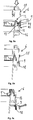
- a respective locking element 9 is mounted together with a respective engagement region 18 on a tab 19 , which is articulated via a film hinge on the side wall 7 of the securing ring 6 and which projects with the engagement region 18 on the underside of the side wall 7.
- a film hinge on the side wall 7 of the securing ring 6 and which projects with the engagement region 18 on the underside of the side wall 7.
- the tab 19 may be connected at their side edges via predetermined breaking points with the side wall 7 of the locking ring 6, the first pivoting of the tab 19 from the in Fig. 4a shown position, so that the tab 19 and the predetermined breaking points form a tamper evidence for the container 1.
- Fig. 5a, b show an example of a locking ring 6, in which, in contrast to the securing rings described above no attack areas 18 are provided for an operator to release the locking elements 9 out of engagement with the underside of the skirt 11.
- the side wall 7 of the locking ring 6 ends in this case, almost directly under the locking elements 9, ie the bottom of the peripheral edge of the locking ring 6 terminates at a distance of less than 10 mm or less than 5 mm from the bottom of the locking elements 9.
- Fig. 5b As this particular in Fig. 5b can be clearly seen, an operator has virtually no chance to act on the locking elements 9 and to release them from the detent position.
- the in Fig. 5a, b Circlip 6 shown, for example, can be used to permanently close disposal containers, such as medical waste containers.
- the release of the locking ring 6 of the container 2 is in principle possible with the aid of a tool, the release of the locking ring 6 is usually not non-destructive.
- Fig. 6a, b show a locking ring 6 with a predetermined breaking element in the form of a tear tab 20 for irreversible separation of the annular, self-contained side wall 7 of the locking ring 6 and the self-contained security area 8.
- the tear tab 20 extends over the entire height of the side wall 7 and over the entire Securing area 8 in order to be able to completely separate the securing ring 6.
- a protruding engagement surface is formed for an operator to facilitate gripping the pull tab 20.
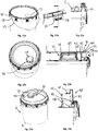
- Fig. 7a, b show a first, lower circlip 6, on which a second, identical upper circlip 6a is stacked.
- the lower securing ring 6 has on its outer side a step 21 which is formed at the transition between the securing area 8 and the side wall 7.
- a horizontal top of the step 21 forms a support surface 22 for supporting the underside of the side wall 7 of the upper locking ring 6a.
- the over the underside of the side wall 7 of the upper locking ring 6a projecting attack areas 18 of the upper locking ring 6a engage in the recesses 17 of the lower locking ring 6, as in Fig. 7a easy to recognize.
- the upper locking ring 6a as desired rest on the support surface 22 of the lower locking ring 6 and on the other hand, by the engagement of the attack areas 18 of the upper locking ring 6a in the recesses 17th the lower securing ring 6 a rotationally secure mounting of the two stacked locking rings 6, 6a are ensured.
- the recesses 17 in this case preferably have a width which is adapted to the width of the engagement areas 18, so that the engagement areas 18 abut with their side edges on the side edges of the recesses 17 almost free of play and the attack areas 18 and thus the upper locking ring 6a laterally relative to fix the lower circlip 6.
- Fig. 8a shows two stacked circlips 6, 6a, like those in Fig. 7a, b shown retaining rings 6, 6a are formed, but in each of which a lid 5 is pre-assembled or held in a form-fitting manner.
- retaining elements 23 in the form of retaining lugs projecting inwards over the side wall 7 are attached to a respective securing ring 6, 6a.
- the cover 5 is in this case received in a form-fitting manner between the respective holding elements 23 and the securing region 8.
- the securing area 8 has for this purpose a U-shaped portion 24 , which surrounds the edge 15 of the lid 5 at its upper side.
- a radially inner leg 25 of the U-shaped portion 24 in this case forms a lateral contact surface for the radially inner edge of the above the lid mirror protruding edge 15 of the lid 5.
- the preassembled cover 5 is located with the underside of the free end of its radially outside lying edge on a support surface which is formed on the upper side of the holding element 23.
- the retaining element 23 is formed on an elastically deformable portion of the side wall 7 in the form of an elastically deformable tongue portion 26 which is mounted in a recess 27 of the side wall 7 forming a window (see also FIG Fig. 7a ).
- the holding member 23 is in this case attached to the free end of the tongue portion 26 and has an inlet slope on which the skirt 11 when sliding the locking ring 6 with the preassembled cover 5 can slide along to under elastic deformation of the tongue portion 26, the holding member 23 to the outside to move the release position.
- the recess 27, in which the tongue portion 26 is formed on the securing portion 8 extends at least as far inward as the holding member 23 to the demolding of the locking ring 6 in the To simplify production in an injection molding process.
- the lid 5 Due to the elastic expansion of the securing ring 7 in the horizontal direction when pushed onto the container 2, the lid 5 can extend elastically horizontally in the region of its clamping profile 14 and thus engage in the groove 13 of the engaging portion 12 of the container 2, as in Fig. 8b is shown.
- the sliding of the locking ring 6 on the container 2 can be done manually or mechanically, both with and without a preassembled cover 5, by after placing the securing ring 6 on the edge 10 of the container 2, an in vertical direction acting force is applied. For this purpose, it is usually necessary to properly orient the snap ring 6, as described below with reference to Fig. 9 is pictured.
- the container 2 two support points 28 for the support of the two ends of a metallic support bracket 29 in the example shown.
- the mounting bracket 29 may also be formed of plastic.
- the securing ring 7 has at two points in the example shown diametrically opposite arranged along the side wall 6 downwardly open, substantially semicircular recesses 30 for receiving the support points 28 and the ends of the support bracket 29. For the sliding of the locking ring 6, it is necessary to position this in the correct direction in the circumferential direction on the container 2, so that the support points 28 can be received by the recesses 30.
- knob-shaped projections 31 are formed on the circumferential side wall 7 of the locking ring, which prevent a rider 1 during transport in a pallet composite.
- two knob-shaped projections 31 are formed on the skirt 11 of the container 2, which are adapted in shape and distance from each other to the shape and spacing of the knob-shaped projections 31 on the side wall 7 of the locking ring 6. In this way, a ride in a pallet composite can be prevented, in which both containers 1, which are secured with a securing ring 6 for transport, as well as containers are transported without a locking ring 6 on a common pallet.
- the cover 5 in the vicinity of its outer edge 15 on the lid mirror upwardly projecting stiffening elements 32 , which are arranged substantially circular. Deformed by the retaining ring 6 secured cover 5 due to an internal pressure in the container 2, this bulges in a not secured by the locking ring 6, radially inner region upwards.
- the stiffening elements 32 are pressed radially outward in the direction of the U-shaped portion 24 of the securing portion 8, more precisely against the radially inner leg 25, as shown in FIG Fig. 10 indicated by an arrow.
- the stiffening elements 32 thus form an additional clamping contour for the cover 5, since a self-locking effect is created by the stiffening elements 32 when the lid 5 bulges, which additionally fixes the lid 5 on the securing ring 6.
- Fig. 11a c show a container 1, in which in the lid 5, more precisely in the region of the lid mirror, a lid opening 33 is formed.
- the lid opening 33 serves to receive a lid adapter for emptying contents from the container 2, as will be described in more detail below.
- the lid opening 33 if it is provided with a suitable lid adapter, in principle also serve to fill the container 2.
- To pour the contents over the lid opening 33 or over the lid adapter it makes sense to align the lid opening 33 with respect to the support points 28 of the support bracket 29, typically such that the lid opening 33 in the middle between the two support points 28th is arranged. In order to achieve this, it is necessary to align the cover 5 in the correct direction relative to the securing ring 6 in the circumferential direction.
- the orientation of the Circlip 6 in the circumferential direction relative to the container 2 is defined by the recesses 30 for receiving the support points 28.
- Indexierelement 34 is formed in the form of a nose, in one of the locking ring 6, more precisely on the side wall 7, formed Indexierrome 35 engages.
- the width of the Indexierelements 34 in the circumferential direction is in this case adapted to the width of the indexing window 35, so that the orientation of the lid 5 relative to the retaining ring 6 can not be practically changed and pouring of the contents through the lid opening 33 as desired centrally between the support points 28 for the mounting bracket 29 can be done.
- Indexierrome 35 one of the recesses 27, in which the resilient tongue portion 26 is formed, can be used by the width of the recess 27 is increased.
- a lid adapter 36 is used, which is closed by a screw cap 37 .
- the lid adapter 36 has an in Fig. 12b to be recognized stub 38 which extends upwards from the lid mirror and having a spout opening 39 to empty the container 2.
- a container 2a of another container on the container 1 it is necessary to create a free space for the upwardly projecting nozzle 38.
- the in Fig. 12a, b Circlip 6 shown a stack area 40 .
- the stacking area 40 is above the securing area 8, more precisely over the top of the U-shaped Subarea 24 of the backup area 8, above about.
- a support surface 41 for the support of the bottom 3 of the further container 2a is formed.
- the support surface 41 of the stacking portion 40 extends at the same height with the top of the rotary closure 37 of the lid adapter 36. In this way, the bottom 3 of the other container 2a is not only on the annular peripheral support surface 41, but the container 2a is additionally supported by the lid adapter 36 and the top of the rotary closure 37.
- the annular circumferential stacking area 40 is integrally formed with the remaining locking ring 6.
- the stacking area 40 in this case adjoins inwardly against the U-shaped subregion 24 of the securing area 8. More specifically, a first outer sidewall 42 of the stacking portion 40 extends upwardly from the inner leg 25 of the U-shaped portion.
- the stack area 40 is substantially U-shaped in cross-section and, in addition to the horizontally extending support surface 41, has a second, inner side wall 43 , which forms the second leg of the U-shaped cross section of the stack area 40.
- the inner side wall 43 of the stacking area 40 extends downwards so far that the free end of the inner side wall 43 rests on the upper side of the lid 5 in order to support the stacking area 40 on the lid 5.
- At the horizontal bearing surface 41 of the stacking area 40 closes at the in Fig. 12a b shown radially outwardly a circumferential, above the support surface 41 projecting collar portion 44 at.
- the collar region 44 serves for the lateral fixing of the position of the further container 2a parked on the support surface 41.
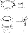
- Fig. 13a, b show a container 1, in which the securing ring 6 also has a stacking area, which is, however, designed in the form of a stacking ring 40.
- the stacking ring 40 is detachably connected to the securing area 8, more precisely to the U-shaped portion 24 of the securing area 8.
- the U-shaped portion 24 has on its inside a circumferential, in cross-section U-shaped groove 45 , in which a free end of the first outer side wall 42 of the stacking ring 40 is received, as in Fig. 13b can be seen.
- the stacking ring 40 has four engagement openings 46 which are formed on the second, radially inner side wall 43 of the stacking ring 40.
- the engagement openings 46 serve to lift the stacking ring 40 from the securing area 8 of the securing ring 6. This may be favorable, for example, when filling material is to be emptied out of the container 2 via the pouring opening 39 formed on the lid adapter 36.
- Fig. 14a, b show a retaining ring 6, on which another, identical retaining ring 6a is stacked.
- the locking ring 6 is as in Fig. 12a, b shown formed and has a stacking area 40.
- the two retaining rings 6, 6a are in this case in connection with the above Fig. 7a, b way described above stacked, ie the upper locking ring 6a rests on the support surface 22 of the lower locking ring 6 and a respective attack area 18 of the upper locking ring 6a engages in a recess 17 of the lower locking ring 6 a.
- use is made of the fact that the two stacking regions 40 of the stacked securing rings 6, 6a have a sufficiently small height so that they do not abut against one another in the stacked state.
- Fig. 15a, b show two stacked circlips 6, 6a, in which, in contrast to the in Fig. 14a, b shown in each case a cover 5 is held, and in the context of the above in connection with Fig. 8a, b described way.
- the upper locking ring 6a is not with the bottom of the circumferential side wall 7, but rather with the bottom of the downward over the side wall 7 projecting attack areas 18 on the support surface 22 of the lower locking ring 6, ie the upper locking ring 6a is opposite the in Fig. 14a shown upper locking ring 6a twisted in the circumferential direction.
- the height of the collar region 44 of the stacking region 40 is selected such that the lid 5 held in the upper securing ring 6a rests on the upper side of the collar region 44, ie the upper side of the collar region 44 forms a support surface for the cover 5 of the upper securing ring 6a.
- stiffening elements 47 are formed on the step 21 of the securing portion 8, on which the support surface 22 is formed, which are formed in the form of stiffening ribs. Between each two adjacent arranged stiffening elements 47, a free space 48 is formed, which has a width which is chosen so that the downwardly projecting engagement portion 18 of the stacked on the circlip 6 upper circlip 6a is fixed in its lateral position.
- the clearance 48 may be adapted, for example, to the width of a respective inwardly projecting beyond the side wall 7 latching element 9, which is formed on the inside of the engagement region 18, so that the latching element 9 can engage in the free space 48 as possible without play.
- the shape of the stiffening elements 47 can be adapted to the shape of the latching elements 9 or the engagement areas 18 in order to achieve a lateral fixation during the stacking.
- Fig. 16 shows a container 1, which has a stacking area 40 which is integrally formed with the securing area 8.
- a pouring trough 49 is formed on the stacking area 40. If the lid adapter 36 is aligned correctly with the aid of the indexing described above for the securing ring 6, the container 2 can be emptied precisely via the pouring trough 49.
- Fig. 17 shows a container 1, in which on the securing ring 6, a band-shaped support bracket 50 is formed, which is attached to two support points 51 on opposite sides of the locking ring 6.
- the mounting bracket 50 is also formed in the example shown from plastic and made in one piece with the retaining ring 6.
- a support bracket 29 which is attached to the support points 28 on the outside of the edge 10 of the container 2.
- Fig. 18 shows a container 1 with a retaining ring 6, which has a downwardly over the inwardly projecting, annular securing portion 8 projecting cover 58 .
- the cover portion 58 is radially inwardly adjacent to the securing portion 8 and has a circumferential, conical side wall projecting downwardly beyond the U-shaped securing portion 8 and into a plane, in horizontal Direction extending cover surface 59 passes.
- the flat cover surface 59 is located at the level of the lid mirror and cover a downwardly projecting, extending into the interior of the container 2 trough-shaped portion 60 of the lid 5 completely.
- the locking ring 6 with the cover 58 thus engages in the in Fig. 18 Example shown, the entire cover 5 from above. Between the cover surface 59 at the level of the lid mirror and the top of the trough-shaped portion 60, a gap 61 is formed in the objects, such as tools, can be stored, which are useful for an operator of the container 1.
- the covering area 58 or the covering area 59 does not have to completely cover the trough-shaped subarea 60, but that in certain applications a partial covering is sufficient.
- the cover portion 58 may also be used to cover one or more portions 60 of the lid 5 which project downwardly and which have a geometry other than a trough-shaped geometry.
- the cover portion 58 may be molded to the securing portion 8 as shown in FIG Fig. 18 is shown, but it is also a detachable attachment to the security area 8 and at the U-shaped portion 24 possible, as described above in connection with the stack area 40.
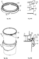
- Fig. 19 shows a container 1, which differs from the containers 1 described above essentially in that it has a rectangular basic shape, and in that on the lid 5 of the container 1, two cover adapter 36 are attached.
- the snap ring 6 has, as in the examples described above, a stacking area 40 for stacking two or more of the containers 2 one above the other.
- Fig. 20a, b show the in Fig. 19 illustrated container 2, in which the screw caps 37 were removed from the Deckeladaptern 36, in an upside down on the upper side of the side wall 4 of another, empty container 2a launched position.
- the retaining ring 6 More precisely the U-shaped portion 24 of the securing portion 8 of the container 2 disposed upside down, a bearing surface 52 which is formed on the upper side of the middle leg of the U-shaped portion.
- the stacking area 40 of the securing ring 6 protrudes into an opening 53 , which is formed on the upper side of the further container 2a.
- a container 1 has been described with a locking ring 6, which is formed from plastic.
- plastic as a material for the circlip 6 is due to the elastic properties, in particular with regard to the possibility of deformation, when pushing and pulling the locking ring 6 on the edge 10 of the container 2 advantageous. But it is also possible to produce the retaining ring 6 of other materials, such as metal.
- Fig. 21a, b show a locking ring 6, which was made of rolled metal.
- the circlip 6 also has a self-contained, circumferential side wall 7, are formed on the recesses 30 for the support points 28 of a support bracket 29.
- the Circlip 6 also has a self-contained, circumferential and inwardly over the side wall 7 projecting securing area 8.
- a latching edge 55 is formed to the retaining ring 6 at the edge of a in Fig. 22a, b shown container 2 to fix.
- the inwardly beyond the side wall 7 projecting securing area 8 has a substantially U-shaped portion 24 which engages around the lid 5 and this secures the container 2.
- a depression 56 is formed directly next to the U-shaped subregion 24, which forms a bearing surface 22 for supporting a further securing ring 6a, more precisely its locking edge 55.
- both two retaining rings 6 and two or more provided with retaining rings 6 container 1 can be stacked.
- the securing ring 6 can in particular serve to cover an opening tab 57 formed on the edge 10 of the container 2, which in FIG Fig. 22a is shown on the upper container 2a.
- the locking edge 55 by means of a tool from engagement under the skirt 11 to solve.
- Fig. 23a, b and Fig. 24a, b show circlips 6, which differ from the in Fig. 22a, b , and Fig. 23a, b essentially differ in that they have a stacking area 40, which, as in the above-described securing rings 6, the Plastic are connected to the security area 8, more precisely to the U-shaped portion 24 of the security area 8, connect and extend from the securing area 8 upwards and there have a support surface 41 for the bottom 3 of a (further) container 2.
- An inner side wall 43 of the stacking portion 40 extends further down than the top of the U-shaped portion 24 to put the stacking portion 40 on the lid 5 of the container 1 secured to the circlip 6 and thereby to support, as shown in FIG Fig. 24b can be seen.
- Fig. 24b is formed by the stacking area 40 a space for over the top of the lid 5 protruding components, for example in the form of Deckeladaptern 36.
- the lid 5 and the container 2 are formed from plastic, since the elasticity of the plastic material simplifies the sliding of the metallic locking ring 6 onto the container 2.
- the plastic material of the container 2, the lid 5 and possibly the securing ring 6 may in particular be polyethylene, polypropylene, polyamides, PET or polyolefins.
- the securing ring 6 can also be produced as a composite or as a combination of plastics and, for example, metallic materials.
- the U-shaped securing region 8 can be produced, for example, in the roll-forming method from tinplate, while the side wall 7 of the securing ring 6 is formed with the latching rim 55 or with the latching elements 9 and the possibly existing stacking region 40 made of plastic.
- the expression of the plastic geometry and the connection with the metal component can take place during an injection molding process.
- a high level of safety during transport of a container 1 can be achieved, which makes it possible to achieve the requirements for UN approval for hazardous substances.
- the containers 1 described above are, in particular, accessible to bucket and canister filling systems, ie they can be filled manually or automatically and emptied again. In this case, if necessary, a substitution of wide-neck barrel applications take place, in which a cover is screwed on for transport protection or secured with a metallic clamping ring.
- lid adapters 36 substitution of canister applications is possible, particularly when the lid adapters 36 are connected to the foil bags 54 described above.
- the use of foil bags 54 is particularly advantageous for use in multi-component applications.
Landscapes
- Engineering & Computer Science (AREA)
- Mechanical Engineering (AREA)
- Closures For Containers (AREA)
Priority Applications (1)
| Application Number | Priority Date | Filing Date | Title |
|---|---|---|---|
| PL19160118T PL3552983T3 (pl) | 2018-03-19 | 2019-02-28 | Zasobnik z pierścieniem zabezpieczającym do zabezpieczania pokrywy podczas transportu |
Applications Claiming Priority (1)
| Application Number | Priority Date | Filing Date | Title |
|---|---|---|---|
| DE102018106314.8A DE102018106314A1 (de) | 2018-03-19 | 2018-03-19 | Sicherungsring zur Transportsicherung eines Deckels und Gebinde |
Publications (3)
| Publication Number | Publication Date |
|---|---|
| EP3552983A2 true EP3552983A2 (fr) | 2019-10-16 |
| EP3552983A3 EP3552983A3 (fr) | 2019-12-25 |
| EP3552983B1 EP3552983B1 (fr) | 2021-04-07 |
Family
ID=65685136
Family Applications (1)
| Application Number | Title | Priority Date | Filing Date |
|---|---|---|---|
| EP19160118.6A Active EP3552983B1 (fr) | 2018-03-19 | 2019-02-28 | Récipient avec bague de sécurité destinée à la sécurité d'un couvercle pour le transport |
Country Status (5)
| Country | Link |
|---|---|
| EP (1) | EP3552983B1 (fr) |
| DE (1) | DE102018106314A1 (fr) |
| DK (1) | DK3552983T3 (fr) |
| ES (1) | ES2871103T3 (fr) |
| PL (1) | PL3552983T3 (fr) |
Families Citing this family (1)
| Publication number | Priority date | Publication date | Assignee | Title |
|---|---|---|---|---|
| DE202019005273U1 (de) * | 2019-12-31 | 2020-02-26 | August Berger Metallwarenfabrik Gmbh | Spannring |
Family Cites Families (16)
| Publication number | Priority date | Publication date | Assignee | Title |
|---|---|---|---|---|
| DD38150A (fr) | ||||
| US3817419A (en) * | 1972-02-22 | 1974-06-18 | Continental Can Co | Latch to secure a closure on a container |
| CH624356A5 (en) * | 1977-11-16 | 1981-07-31 | Vogel Bmw Ag | Container with lid |
| DE3908099A1 (de) * | 1989-03-13 | 1990-09-27 | Schuetz Werke Gmbh Co Kg | Fass |
| DE8910359U1 (de) | 1989-08-30 | 1989-10-19 | Latza GmbH, 5952 Attendorn | Behälterverschluß eines Metallbehälters |
| DE9012138U1 (de) | 1990-07-24 | 1990-10-18 | Stebler & Co AG, Nunningen | Spannring zum Festhalten eines Deckels in einem Eimer und Vorrichtung zum Schliessen dieses Spannringes |
| DE9306741U1 (de) * | 1993-05-06 | 1993-10-14 | Mauser-Werke GmbH, 50321 Brühl | Spundfaß mit Inliner |
| WO1994027880A1 (fr) * | 1993-05-21 | 1994-12-08 | Beierling, Uwe | Corps creux a couvercle a fermeture amovible |
| DE9417502U1 (de) | 1994-10-31 | 1994-12-15 | Siepe GmbH, 50170 Kerpen | Spannringverschluß für Behälter, insbesondere für Fäßer |
| DE10005299A1 (de) | 1999-02-07 | 2001-01-25 | Impress Gmbh & Co Ohg | Verschließen von eimerförmigen Behältern |
| FR2801873B1 (fr) * | 1999-12-03 | 2002-02-15 | Corepe | Recipient a ouverture totale pour divers liquides tels que peintures et vernis |
| EP1976767A1 (fr) * | 2005-12-30 | 2008-10-08 | CROWN Packaging Technology, Inc. | Emballage contenant / fermeture à étanchéité améliorée |
| DE202009016507U1 (de) * | 2009-12-08 | 2010-06-24 | Impress Group Bv | Behälter umfassend einen wiederverschließbaren Deckel mit einem elastischen Ring |
| SG194743A1 (en) * | 2011-05-09 | 2013-12-30 | Abbott Lab | Container and closure |
| SE538415C2 (sv) * | 2011-09-20 | 2016-06-21 | Emballator Ulricehamns Bleck Ab | Behållare med lock |
| US8550268B1 (en) * | 2012-07-10 | 2013-10-08 | Owens-Brockway Glass Container Inc. | Package with glass container and glass closure |
-
2018
- 2018-03-19 DE DE102018106314.8A patent/DE102018106314A1/de not_active Withdrawn
-
2019
- 2019-02-28 ES ES19160118T patent/ES2871103T3/es active Active
- 2019-02-28 DK DK19160118.6T patent/DK3552983T3/da active
- 2019-02-28 EP EP19160118.6A patent/EP3552983B1/fr active Active
- 2019-02-28 PL PL19160118T patent/PL3552983T3/pl unknown
Also Published As
| Publication number | Publication date |
|---|---|
| ES2871103T3 (es) | 2021-10-28 |
| PL3552983T3 (pl) | 2021-10-11 |
| DE102018106314A1 (de) | 2019-09-19 |
| DK3552983T3 (da) | 2021-05-10 |
| EP3552983B1 (fr) | 2021-04-07 |
| EP3552983A3 (fr) | 2019-12-25 |
Similar Documents
| Publication | Publication Date | Title |
|---|---|---|
| DE3043899C2 (fr) | ||
| EP4403486A1 (fr) | Bouchon imperdable présentant un angle d'ouverture stabilisé | |
| EP1747151A1 (fr) | Couvercle à l' épreuve des manipulations | |
| EP4061736B1 (fr) | Fermeture de récipient | |
| DE8814315U1 (de) | Mischvorrichtung | |
| EP0639138A1 (fr) | Fut en plastique. | |
| DE2215778A1 (de) | Behälterverschluß | |
| EP0675051B1 (fr) | Capuchon à vis avec un anneau soudé | |
| DE102005038929A1 (de) | Abgabeverschluß | |
| WO2005087604A1 (fr) | Bouchon rotatif de securite destine a une bouteille a plusieurs compartiments, notamment a une bouteille a deux compartiments | |
| DE8228681U1 (de) | Blechdeckel fuer eine Dose fuer fluessiges Fuellgut | |
| EP3552983B1 (fr) | Récipient avec bague de sécurité destinée à la sécurité d'un couvercle pour le transport | |
| EP2070826B1 (fr) | Récipient doté d'un élément de fermeture à ouverture facile | |
| WO1998045189A1 (fr) | Element soude verseur en plastique | |
| EP3981703B1 (fr) | Récipient pourvu de couvercle pouvant être ajuster par pression | |
| EP0115249B1 (fr) | Récipient en matière plastique avec couvercle | |
| DE202009012302U1 (de) | Behälter mit Bördelrändern | |
| EP4037989B1 (fr) | Fermeture de récipient | |
| DE102018003627A1 (de) | Behälter für Anstrichmittel mit einer nachgiebigen Tasche | |
| EP1218255A1 (fr) | Procede d'etancheification d'une ouverture a verser d'un recipient, ainsi que recipient dote d'une ouverture a verser etancheifiee | |
| WO2011160831A1 (fr) | Dispositif de versement à ouverture automatique | |
| EP4144660B1 (fr) | Seau pourvu de fond et de paroi latérale en feuille, ainsi que récipient | |
| EP3543171B1 (fr) | Adaptateur de couvercle, couvercle, contenant et procédé de vidage d'au moins un sachet en film | |
| EP0436083A1 (fr) | Embout de soutirage en matière plastique | |
| DE602004010508T2 (de) | Zapfen für Getränkebehälter |
Legal Events
| Date | Code | Title | Description |
|---|---|---|---|
| PUAI | Public reference made under article 153(3) epc to a published international application that has entered the european phase |
Free format text: ORIGINAL CODE: 0009012 |
|
| STAA | Information on the status of an ep patent application or granted ep patent |
Free format text: STATUS: THE APPLICATION HAS BEEN PUBLISHED |
|
| AK | Designated contracting states |
Kind code of ref document: A2 Designated state(s): AL AT BE BG CH CY CZ DE DK EE ES FI FR GB GR HR HU IE IS IT LI LT LU LV MC MK MT NL NO PL PT RO RS SE SI SK SM TR |
|
| AX | Request for extension of the european patent |
Extension state: BA ME |
|
| PUAL | Search report despatched |
Free format text: ORIGINAL CODE: 0009013 |
|
| AK | Designated contracting states |
Kind code of ref document: A3 Designated state(s): AL AT BE BG CH CY CZ DE DK EE ES FI FR GB GR HR HU IE IS IT LI LT LU LV MC MK MT NL NO PL PT RO RS SE SI SK SM TR |
|
| AX | Request for extension of the european patent |
Extension state: BA ME |
|
| RIC1 | Information provided on ipc code assigned before grant |
Ipc: B65D 45/30 20060101AFI20191120BHEP |
|
| STAA | Information on the status of an ep patent application or granted ep patent |
Free format text: STATUS: REQUEST FOR EXAMINATION WAS MADE |
|
| 17P | Request for examination filed |
Effective date: 20200417 |
|
| RBV | Designated contracting states (corrected) |
Designated state(s): AL AT BE BG CH CY CZ DE DK EE ES FI FR GB GR HR HU IE IS IT LI LT LU LV MC MK MT NL NO PL PT RO RS SE SI SK SM TR |
|
| STAA | Information on the status of an ep patent application or granted ep patent |
Free format text: STATUS: EXAMINATION IS IN PROGRESS |
|
| 17Q | First examination report despatched |
Effective date: 20200806 |
|
| GRAP | Despatch of communication of intention to grant a patent |
Free format text: ORIGINAL CODE: EPIDOSNIGR1 |
|
| STAA | Information on the status of an ep patent application or granted ep patent |
Free format text: STATUS: GRANT OF PATENT IS INTENDED |
|
| INTG | Intention to grant announced |
Effective date: 20201215 |
|
| GRAS | Grant fee paid |
Free format text: ORIGINAL CODE: EPIDOSNIGR3 |
|
| GRAA | (expected) grant |
Free format text: ORIGINAL CODE: 0009210 |
|
| STAA | Information on the status of an ep patent application or granted ep patent |
Free format text: STATUS: THE PATENT HAS BEEN GRANTED |
|
| AK | Designated contracting states |
Kind code of ref document: B1 Designated state(s): AL AT BE BG CH CY CZ DE DK EE ES FI FR GB GR HR HU IE IS IT LI LT LU LV MC MK MT NL NO PL PT RO RS SE SI SK SM TR |
|
| REG | Reference to a national code |
Ref country code: GB Ref legal event code: FG4D Free format text: NOT ENGLISH |
|
| REG | Reference to a national code |
Ref country code: CH Ref legal event code: EP Ref country code: AT Ref legal event code: REF Ref document number: 1379432 Country of ref document: AT Kind code of ref document: T Effective date: 20210415 |
|
| REG | Reference to a national code |
Ref country code: DE Ref legal event code: R096 Ref document number: 502019001151 Country of ref document: DE |
|
| REG | Reference to a national code |
Ref country code: DK Ref legal event code: T3 Effective date: 20210504 |
|
| REG | Reference to a national code |
Ref country code: IE Ref legal event code: FG4D Free format text: LANGUAGE OF EP DOCUMENT: GERMAN |
|
| REG | Reference to a national code |
Ref country code: SE Ref legal event code: TRGR |
|
| REG | Reference to a national code |
Ref country code: NL Ref legal event code: FP |
|
| REG | Reference to a national code |
Ref country code: NO Ref legal event code: T2 Effective date: 20210407 |
|
| REG | Reference to a national code |
Ref country code: LT Ref legal event code: MG9D |
|
| REG | Reference to a national code |
Ref country code: ES Ref legal event code: FG2A Ref document number: 2871103 Country of ref document: ES Kind code of ref document: T3 Effective date: 20211028 |
|
| PG25 | Lapsed in a contracting state [announced via postgrant information from national office to epo] |
Ref country code: BG Free format text: LAPSE BECAUSE OF FAILURE TO SUBMIT A TRANSLATION OF THE DESCRIPTION OR TO PAY THE FEE WITHIN THE PRESCRIBED TIME-LIMIT Effective date: 20210707 Ref country code: LT Free format text: LAPSE BECAUSE OF FAILURE TO SUBMIT A TRANSLATION OF THE DESCRIPTION OR TO PAY THE FEE WITHIN THE PRESCRIBED TIME-LIMIT Effective date: 20210407 Ref country code: HR Free format text: LAPSE BECAUSE OF FAILURE TO SUBMIT A TRANSLATION OF THE DESCRIPTION OR TO PAY THE FEE WITHIN THE PRESCRIBED TIME-LIMIT Effective date: 20210407 Ref country code: FI Free format text: LAPSE BECAUSE OF FAILURE TO SUBMIT A TRANSLATION OF THE DESCRIPTION OR TO PAY THE FEE WITHIN THE PRESCRIBED TIME-LIMIT Effective date: 20210407 |
|
| PG25 | Lapsed in a contracting state [announced via postgrant information from national office to epo] |
Ref country code: RS Free format text: LAPSE BECAUSE OF FAILURE TO SUBMIT A TRANSLATION OF THE DESCRIPTION OR TO PAY THE FEE WITHIN THE PRESCRIBED TIME-LIMIT Effective date: 20210407 Ref country code: PT Free format text: LAPSE BECAUSE OF FAILURE TO SUBMIT A TRANSLATION OF THE DESCRIPTION OR TO PAY THE FEE WITHIN THE PRESCRIBED TIME-LIMIT Effective date: 20210809 Ref country code: LV Free format text: LAPSE BECAUSE OF FAILURE TO SUBMIT A TRANSLATION OF THE DESCRIPTION OR TO PAY THE FEE WITHIN THE PRESCRIBED TIME-LIMIT Effective date: 20210407 Ref country code: GR Free format text: LAPSE BECAUSE OF FAILURE TO SUBMIT A TRANSLATION OF THE DESCRIPTION OR TO PAY THE FEE WITHIN THE PRESCRIBED TIME-LIMIT Effective date: 20210708 Ref country code: IS Free format text: LAPSE BECAUSE OF FAILURE TO SUBMIT A TRANSLATION OF THE DESCRIPTION OR TO PAY THE FEE WITHIN THE PRESCRIBED TIME-LIMIT Effective date: 20210807 |
|
| REG | Reference to a national code |
Ref country code: DE Ref legal event code: R097 Ref document number: 502019001151 Country of ref document: DE |
|
| PG25 | Lapsed in a contracting state [announced via postgrant information from national office to epo] |
Ref country code: EE Free format text: LAPSE BECAUSE OF FAILURE TO SUBMIT A TRANSLATION OF THE DESCRIPTION OR TO PAY THE FEE WITHIN THE PRESCRIBED TIME-LIMIT Effective date: 20210407 Ref country code: SK Free format text: LAPSE BECAUSE OF FAILURE TO SUBMIT A TRANSLATION OF THE DESCRIPTION OR TO PAY THE FEE WITHIN THE PRESCRIBED TIME-LIMIT Effective date: 20210407 Ref country code: CZ Free format text: LAPSE BECAUSE OF FAILURE TO SUBMIT A TRANSLATION OF THE DESCRIPTION OR TO PAY THE FEE WITHIN THE PRESCRIBED TIME-LIMIT Effective date: 20210407 Ref country code: RO Free format text: LAPSE BECAUSE OF FAILURE TO SUBMIT A TRANSLATION OF THE DESCRIPTION OR TO PAY THE FEE WITHIN THE PRESCRIBED TIME-LIMIT Effective date: 20210407 Ref country code: SM Free format text: LAPSE BECAUSE OF FAILURE TO SUBMIT A TRANSLATION OF THE DESCRIPTION OR TO PAY THE FEE WITHIN THE PRESCRIBED TIME-LIMIT Effective date: 20210407 |
|
| PLBE | No opposition filed within time limit |
Free format text: ORIGINAL CODE: 0009261 |
|
| STAA | Information on the status of an ep patent application or granted ep patent |
Free format text: STATUS: NO OPPOSITION FILED WITHIN TIME LIMIT |
|
| 26N | No opposition filed |
Effective date: 20220110 |
|
| PG25 | Lapsed in a contracting state [announced via postgrant information from national office to epo] |
Ref country code: IS Free format text: LAPSE BECAUSE OF FAILURE TO SUBMIT A TRANSLATION OF THE DESCRIPTION OR TO PAY THE FEE WITHIN THE PRESCRIBED TIME-LIMIT Effective date: 20210807 Ref country code: AL Free format text: LAPSE BECAUSE OF FAILURE TO SUBMIT A TRANSLATION OF THE DESCRIPTION OR TO PAY THE FEE WITHIN THE PRESCRIBED TIME-LIMIT Effective date: 20210407 |
|
| PG25 | Lapsed in a contracting state [announced via postgrant information from national office to epo] |
Ref country code: MC Free format text: LAPSE BECAUSE OF FAILURE TO SUBMIT A TRANSLATION OF THE DESCRIPTION OR TO PAY THE FEE WITHIN THE PRESCRIBED TIME-LIMIT Effective date: 20210407 |
|
| PG25 | Lapsed in a contracting state [announced via postgrant information from national office to epo] |
Ref country code: LU Free format text: LAPSE BECAUSE OF NON-PAYMENT OF DUE FEES Effective date: 20220228 |
|
| PG25 | Lapsed in a contracting state [announced via postgrant information from national office to epo] |
Ref country code: IE Free format text: LAPSE BECAUSE OF NON-PAYMENT OF DUE FEES Effective date: 20220228 |
|
| PG25 | Lapsed in a contracting state [announced via postgrant information from national office to epo] |
Ref country code: MK Free format text: LAPSE BECAUSE OF FAILURE TO SUBMIT A TRANSLATION OF THE DESCRIPTION OR TO PAY THE FEE WITHIN THE PRESCRIBED TIME-LIMIT Effective date: 20210407 Ref country code: CY Free format text: LAPSE BECAUSE OF FAILURE TO SUBMIT A TRANSLATION OF THE DESCRIPTION OR TO PAY THE FEE WITHIN THE PRESCRIBED TIME-LIMIT Effective date: 20210407 |
|
| PG25 | Lapsed in a contracting state [announced via postgrant information from national office to epo] |
Ref country code: HU Free format text: LAPSE BECAUSE OF FAILURE TO SUBMIT A TRANSLATION OF THE DESCRIPTION OR TO PAY THE FEE WITHIN THE PRESCRIBED TIME-LIMIT; INVALID AB INITIO Effective date: 20190228 |
|
| PG25 | Lapsed in a contracting state [announced via postgrant information from national office to epo] |
Ref country code: MT Free format text: LAPSE BECAUSE OF FAILURE TO SUBMIT A TRANSLATION OF THE DESCRIPTION OR TO PAY THE FEE WITHIN THE PRESCRIBED TIME-LIMIT Effective date: 20210407 |
|
| PGFP | Annual fee paid to national office [announced via postgrant information from national office to epo] |
Ref country code: DE Payment date: 20250225 Year of fee payment: 7 |
|
| PGFP | Annual fee paid to national office [announced via postgrant information from national office to epo] |
Ref country code: DK Payment date: 20250219 Year of fee payment: 7 |
|
| PGFP | Annual fee paid to national office [announced via postgrant information from national office to epo] |
Ref country code: ES Payment date: 20250318 Year of fee payment: 7 |
|
| PGFP | Annual fee paid to national office [announced via postgrant information from national office to epo] |
Ref country code: SE Payment date: 20250219 Year of fee payment: 7 |
|
| PGFP | Annual fee paid to national office [announced via postgrant information from national office to epo] |
Ref country code: NO Payment date: 20250218 Year of fee payment: 7 |
|
| PGFP | Annual fee paid to national office [announced via postgrant information from national office to epo] |
Ref country code: BE Payment date: 20250218 Year of fee payment: 7 Ref country code: AT Payment date: 20250217 Year of fee payment: 7 Ref country code: CH Payment date: 20250301 Year of fee payment: 7 |
|
| PGFP | Annual fee paid to national office [announced via postgrant information from national office to epo] |
Ref country code: FR Payment date: 20250220 Year of fee payment: 7 |
|
| PGFP | Annual fee paid to national office [announced via postgrant information from national office to epo] |
Ref country code: IT Payment date: 20250228 Year of fee payment: 7 Ref country code: GB Payment date: 20250220 Year of fee payment: 7 |
|
| PG25 | Lapsed in a contracting state [announced via postgrant information from national office to epo] |
Ref country code: TR Free format text: LAPSE BECAUSE OF FAILURE TO SUBMIT A TRANSLATION OF THE DESCRIPTION OR TO PAY THE FEE WITHIN THE PRESCRIBED TIME-LIMIT Effective date: 20210407 |
|
| PGFP | Annual fee paid to national office [announced via postgrant information from national office to epo] |
Ref country code: PL Payment date: 20251107 Year of fee payment: 8 |
|
| REG | Reference to a national code |
Ref country code: CH Ref legal event code: U11 Free format text: ST27 STATUS EVENT CODE: U-0-0-U10-U11 (AS PROVIDED BY THE NATIONAL OFFICE) Effective date: 20260301 |
|
| PGFP | Annual fee paid to national office [announced via postgrant information from national office to epo] |
Ref country code: NL Payment date: 20260218 Year of fee payment: 8 |