EP3552931A1 - Steighilfe - Google Patents
Steighilfe Download PDFInfo
- Publication number
- EP3552931A1 EP3552931A1 EP19161269.6A EP19161269A EP3552931A1 EP 3552931 A1 EP3552931 A1 EP 3552931A1 EP 19161269 A EP19161269 A EP 19161269A EP 3552931 A1 EP3552931 A1 EP 3552931A1
- Authority
- EP
- European Patent Office
- Prior art keywords
- profile
- climbing aid
- profile elements
- recess
- elements
- Prior art date
- Legal status (The legal status is an assumption and is not a legal conclusion. Google has not performed a legal analysis and makes no representation as to the accuracy of the status listed.)
- Granted
Links
Images


Classifications
-
- B—PERFORMING OPERATIONS; TRANSPORTING
- B62—LAND VEHICLES FOR TRAVELLING OTHERWISE THAN ON RAILS
- B62D—MOTOR VEHICLES; TRAILERS
- B62D55/00—Endless track vehicles
- B62D55/08—Endless track units; Parts thereof
- B62D55/18—Tracks
- B62D55/26—Ground engaging parts or elements
- B62D55/27—Ground engaging parts or elements having different types of crampons for progression over varying ground
-
- B—PERFORMING OPERATIONS; TRANSPORTING
- B62—LAND VEHICLES FOR TRAVELLING OTHERWISE THAN ON RAILS
- B62D—MOTOR VEHICLES; TRAILERS
- B62D55/00—Endless track vehicles
- B62D55/08—Endless track units; Parts thereof
- B62D55/18—Tracks
- B62D55/26—Ground engaging parts or elements
- B62D55/28—Ground engaging parts or elements detachable
- B62D55/283—Ground engaging parts or elements detachable and movable, e.g. around an axis or perpendicularly to the track
-
- B—PERFORMING OPERATIONS; TRANSPORTING
- B62—LAND VEHICLES FOR TRAVELLING OTHERWISE THAN ON RAILS
- B62D—MOTOR VEHICLES; TRAILERS
- B62D55/00—Endless track vehicles
- B62D55/08—Endless track units; Parts thereof
- B62D55/18—Tracks
- B62D55/26—Ground engaging parts or elements
- B62D55/28—Ground engaging parts or elements detachable
Definitions
- the invention relates to a climbing aid for a machine with a crawler, comprising a base body which is formed from each other connected to a lap joint profile elements, wherein the profile elements have a carrier profile on which a climbing aid profile element is arranged, which projects beyond the carrier profile, and wherein the profile elements of the base body in the region of the lap joint are positively connected to each other.
- the invention relates to a crawler for a machine, with chain plates, which have an upper surface, wherein the top has a profiling with elevations, and with at least one climbing aid, which is arranged between two elevations of the profiling of the top of the chain plates, and U-shaped Holding elements for arranging the climbing aid on the crawler, which engage around the side edges of the chain plates.
- the present invention has for its object to improve such a non-slip device in terms of mechanical strength.
- This object of the invention is achieved in the initial climbing aid characterized in that for the formation of the positive connection of the profile elements, at least one of these profile elements frontally has a recess and the profile elements are pushed into each other in the region of this recess.
- the advantage here is that by the telescoping of the two profile elements, the positive engagement produced by a higher transverse stiffness, whereby the climbing aid after it is mounted with its longitudinal extent transverse to the direction of travel, higher forces in the direction of travel can be suspended.
- higher security of the connection of the two profile elements in the lap joint against unintentional loosening in operation of the climbing aid can be achieved because a relative movement of the profile elements in the direction of travel can be better prevented each other.
- this positive connection in the production of climbing aid is easy to represent.
- both the form-fitting forming profile elements frontally have a recess, whereby the depth of the recesses (viewed in the longitudinal direction of the climbing aid) can be made smaller in the individual profile elements. It can thus be achieved by the recess less material weakening in the profile elements.
- a recess of the positive connection in one of the carrier profiles and the further recess is formed in one of the climbing aid profile elements.
- the profile elements lie flat against each other in the lap joint, whereby the lap joint of the profile elements can be made simpler.
- connection areas of the climbing aid can be provided that the overlapping joint forming surfaces and / or the form-fitting surfaces of the profile elements are provided with a friction-increasing coating.
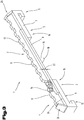
- Fig. 1 to 3 is a preferred embodiment of a climbing aid 1 shown.
- the climbing aid 1 also referred to as anti-skid device, is provided for a crawler, not shown, of a machine, such as an excavator or a snowcat.
- crawlers have from each other via hinge pins hingedly connected chain links and screwed on these chain links chain plates.
- the chain plates have on a top, which comes into contact with the ground on which the machine is in contact, a profiling with surveys, for example, with transverse to the chain longitudinal direction, protruding webs.
- the profiling can also be done differently, but with the restriction that the profiling does not interfere with the assembly of the climbing aid on the track.
- the crawler may be insufficiently supported.
- the climbing aid 1 can be mounted on the track.
- the climbing aid 1 is arranged between two surveys, for example, between two immediately adjacent, transverse to the direction of webs, the profiling.
- the climbing aid 1 comprises one or consists of a base body which is formed from each other connected to a lap joint 2 profile elements 3, 4.
- more than two profile elements 3, 4 may be provided, for example, three or four, so that more al a lap joint 2 may be formed.
- the embodiment with only two profile elements 3, 4 is the preferred.
- the first profile elements 3 has a first carrier profile 5 and the second profile elements 4 a second carrier profile 6.
- the first carrier profile 5 is executed in two parts in the illustrated embodiment, and has on a first carrier profile part 7, a second carrier profile part 8, which is connected to the first carrier profile part 7, in particular is materially connected, preferably connected by welding.
- second support section 5 is preferably made in one piece, but may also have several parts.
- the two carrier profiles 5, 6 holding elements 9, 10, which are preferably formed integrally with the carrier profiles 5, 6.
- These holding elements 9, 10 are in particular U-shaped, so that the two carrier profiles 5, 6, the side regions of the respective chain plate on which the climbing aid 1 is arranged, can be arranged encompassing on both sides.
- the two carrier profiles 5, 6 are preferably made of a flat steel by appropriate forming, but can at least partially but also by another method, e.g. a casting process.
- a first climbing aid profile element 11 and on the second carrier profile 6, a second climbing aid profile element 12 is arranged on the first carrier profile 5, a first climbing aid profile element 11 and on the second carrier profile 6, a second climbing aid profile element 12 is arranged.
- the two climbing aid profile element 11, 12 are connected to the respective carrier profile 5, 6, in particular materially connected, preferably welded.
- the two climbing aid profile elements 11, 12 are arranged rotated by 90 ° on the respective carrier profile 5, 6, so lie with a side end face on the support profiles 5, 6, as shown in FIGS. 1 to 3 is apparent.
- the two climbing aid profile elements 11, 12 are in particular likewise produced from a flat material by machining, can also be produced by another method, e.g. a casting process. They each have a profiling with elevations 13 and extend beyond the carrier profiles 5, 6 in the vertical direction. With this profiling, which also dominates the profiling of the chain plates in the vertical direction, the caterpillar track will find a better grip during operation as it can dig deeper into the ground.
- FIGS. 1 to 3 illustrated shape of the profiling of the climbing aid profile elements 11, 12 has no limiting character, but may also be designed differently, for example, with triangular elevations, etc.
- climbing aid 1 is conventionally mounted on the track. Since preferably all climbing aids are identical, only a climbing aid 1 is described in this description. However, these embodiments can also be applied to the other climbing aids 1 of the caterpillar track.
- the two profile elements 3, 4 are interconnected. Preferably, they are bolted together by screws 14.
- two screws 14 are provided. Preferably, these are arranged diagonally offset from each other, as shown in the Fig. 2 and 3 is apparent. It can thus be achieved a higher security of the screw.
- the screwing can be carried out by means of nuts or by means of thread in the respective lower profile element 4.
- the screwing of the two profile elements 3, 4 with each other off-center (based on a longitudinal extension 15 of the climbing aid 1). But it can also be performed in the middle.
- At least one support profile 16 is arranged on the underside of the first carrier profile 5 and is connected to the first carrier profile 5, via which the climbing aid 1 can additionally be supported on the upper side of the chain plate of the endless track. With only one support profile 16, this is arranged at least approximately centrally (relative to the longitudinal extent 16) on the climbing aid 1.
- two or three or more support profiles 16 can be provided.
- a height 17 of the at least one support profile 16 depends on the material thickness of the carrier profiles 5, 6.
- An end face 18 of the at least one support profile 16 is at least approximately aligned with a bottom 19 (next to the U-shaped holding elements 9, 10) of the carrier profiles. 5 , 6 arranged.
- the profile elements 3, 4 in the lap joint 2 are positively connected with each other.
- the recess 21 is formed exclusively in the first profile part 3.
- the recess 21 can also be formed exclusively in the second profile part 4.
- the two profile parts 3, 4 are pushed into each other in the region of the recess 21 to form the positive connection, as for example Fig. 3 is apparent.
- the recess 21 extends in the embodiment of the climbing aid 1 after Fig. 4 through an entire thickness 22 ( Fig. 3 ) of the carrier profile 3 in the region of the positive connection (viewed in the vertical direction). Furthermore, the recess 21 extends in the direction of the longitudinal extent 15 (FIG. Fig. 2 The size of the depth 23 may be adapted to the respective requirements of the climbing aid 1 and, for example, between 2% and 10% of the total length of the climbing aid 1 in the direction of the longitudinal extent 15 amount.
- the shape of the recess 21 depends on the shape of the second profile part 4 in the region in which it is pushed into the recess 21.
- the recess may have a rectangular shape - viewed in plan view.
- both the form-fitting forming profile elements 3, 4 each end face a recess 21, as shown in Fig. 5 is shown, which shows a side view of a section of a further embodiment of the climbing aid 1.
- Fig. 5 shows a side view of a section of a further embodiment of the climbing aid 1.
- the above statements apply to both recesses 21, although the (total) depth 23 (FIG. Fig. 4 ) of the recess 21 is now divided into two recesses 21.
- the partition may be selected from a range of 60:40 to 40:60, and 50:50, for example.
- the numbers are in% based on the total depth of the recesses in the horizontal direction.
- the positive connection between the two profile parts 3, 4 can be formed over the at least one recess 21 on the front side of any suitable location.
- the recess 21 may be formed in the carrier profile 6 of the second profile part 4.
- the carrier profile 5 of the first profile part 3 may have a vertically downwardly projecting web to form the positive connection, which engages in the recess 21 of the carrier profile 6 of the second profile part 3.
- a recess 21 of the positive connection in one of the carrier profiles 5, 6 and the further recess 21 in one of the climbing aid profile elements 11, 12 is formed.
- the recess 21 in the climbing aid profile element 12 extends from the footprint 24 (also from Fig. 3 visible) on the carrier profile 6 of the second profile element 4 via a vertical height 25 which at least approximately corresponds to the thickness 22 of the carrier profile 5 of the first profile element 3 in this area.
- the height 25 is dimensioned so that the telescoping of the two profile elements 3, 4 is possible and at the same time the positive connection between the profile elements 3, 4 is formed.
- the height 25 will therefore only be slightly larger than the thickness 22.
- the profile elements 3, 4 lie flat against each other in the lap joint 2.
- the surfaces forming the overlap joint 2 and / or the surfaces forming the positive connection the profile elements 3, 4 are provided with a friction-increasing coating.
- This coating can be performed, for example, resin-based, for example, be a paint.
- Hard particles, such as corundum particles or diamond particles, etc., can be used in the coating to increase the friction.
- the above statements apply to the connection of the two profile elements 3, 4 also for, the number two exceeding number of profile elements.
- the in the Fig. 1 to 3 shown right lap joint as the illustrated and described left lap joint 2 with the frontal form fit between the profile elements 3, 4 executed.
- At least one slot may be provided in one of the profile elements 3, 4, as in the DE 20 2012 100 868 U1 is described.
- the two U-shaped holding elements 9, 10 are pushed from opposite sides to the side edges of the chain plates between two adjacent elevations of the profile of the chain plates and then pushed the two profile elements 3, 4 to form the positive connection. Subsequently, the two profile elements 3, 4 are screwed together in the trained lap joint with at least one screw 14.
- ice claws can be provided for particularly harsh winter conditions. These ice claws may for example be formed plate-shaped, and be formed at its front end to the elevations 13 of the climbing aid profile elements 11, 12 similar elevations. The ice claws can be arranged at least orthogonal to the climbing aid profile elements 11, 12 on the climbing aid profile elements 11, 12.
- plate-shaped protective elements 26 in the lateral areas of the climbing aid and with the climbing aid profile elements 11, 12 and / or the carrier profiles 5, 6 to connect, like this for example Fig. 3 is apparent.
- These protective elements 26 may be formed, for example, a trapezoidal shape.
- the described separable positive connection of the two profile elements 3, 4 with each other in the form-fitting in addition also be designed non-positively.
- the exemplary embodiments show or describe possible design variants of the climbing aid 1, wherein it should be noted at this point that combinations of the individual design variants are also possible with one another.
Landscapes
- Engineering & Computer Science (AREA)
- Chemical & Material Sciences (AREA)
- Combustion & Propulsion (AREA)
- Transportation (AREA)
- Mechanical Engineering (AREA)
- Joining Of Building Structures In Genera (AREA)
- Road Paving Structures (AREA)
Abstract
Description
- Die Erfindung betrifft eine Steighilfe für eine Maschine mit einer Raupenkette, umfassend einen Grundkörper, der aus miteinander an einem Überlappstoß verbundenen Profilelementen gebildet ist, wobei die Profilelemente ein Trägerprofil aufweisen, auf dem ein Steighilfe-Profilelement angeordnet ist, das über das Trägerprofil vorragt, und wobei die Profilelemente des Grundkörpers im Bereich des Überlappstoßes formschlüssig miteinander verbunden sind.
- Weiter betrifft die Erfindung eine Raupenkette für eine Maschine, mit Kettenplatten, die eine Oberseite aufweisen, wobei die Oberseite eine Profilierung mit Erhebungen aufweist, sowie mit zumindest einer Steighilfe, die zwischen zwei Erhebungen der Profilierung der Oberseite der Kettenplatten angeordnet ist, und U-förmige Halteelemente zur Anordnung der Steighilfe auf der Raupenkette aufweist, die die Seitenränder der Kettenplatten umgreifen.
- Die Bodenhaftung von Raupenfahrzeugen, wie beispielsweise Baggern, leidet bei schlechten Bodenverhältnissen bzw. steilen Geländen, weil sich die Zwischenräume zwischen den vorstehenden Querstegen der Kettenplatten der Raupenkette innerhalb kurzer Zeit mit aufgenommenem Material füllen und dann nicht mehr in den Boden eindringen, sodass sie unwirksam werden. Um diesem Umstand Rechnung zu tragen, wurden im Stand der Technik bereits Steighilfen vorgeschlagen. So ist beispielsweise aus der
DE 20 2012 100 868 U1 eine Gleitschutzvorrichtung für eine Raupenkette bekannt, deren Kettenplatten vorstehende, quer zur Kettenlängsrichtung verlaufende Stege aufweisen, mit Trägern für über die Stege vorstehende Stollen zwischen je zwei benachbarten Stegen ausgewählter Kettenplatten, wobei die Träger jeweils zwei die Seitenränder der Kettenplatten umgreifende, miteinander lösbar verbundene, U-förmige Halterungen bilden. Die U-förmigen Halterungen der Träger umfassen einander in Trägerlängsrichtung der Höhe nach überlappende und im Überlappungsbereich mit gegen die zugehörige U-förmige Halterung abfallenden Keilflächen aneinander liegende Schenkel, die im Überlappungsbereich über eine Langlochverbindung verschraubt sind. - Der vorliegenden Erfindung liegt die Aufgabe zugrunde, eine derartige Gleitschutzvorrichtung hinsichtlich der mechanischen Belastbarkeit zu verbessern.
- Diese Aufgabe der Erfindung wird bei der eingangs Steighilfe dadurch gelöst, dass für die Ausbildung der formschlüssigen Verbindung der Profilelemente, zumindest eines dieser Profilelemente stirnseitig eine Ausnehmung aufweist und die Profilelemente im Bereich dieser Ausnehmung ineinandergeschoben sind.
- Weiter wird die Aufgabe der Erfindung mit der eingangs genannten Raupenkette gelöst, bei der die Steighilfe erfindungsgemäß ausgebildet ist.
- Von Vorteil ist dabei, dass durch das Ineinanderschieben der beiden Profilelemente, der dadurch erzeugte Formschluss eine höhere Quersteifigkeit aufweist, wodurch die Steighilfe, nachdem sie mit ihrer Längserstreckung quer zur Fahrtrichtung montiert ist, höheren Kräften in Fahrtrichtung ausgesetzt werden kann. Zudem kann mit diesem Formschluss eine höhere Sicherheit der Verbindung der beiden Profilelemente im Überlappstoß gegen unbeabsichtigtes Lösen im Betrieb der Steighilfe erreicht werden, da eine Relativbewegung der Profilelemente in Fahrtrichtung zueinander besser verhindert werden kann. Darüber hinaus ist dieser Formschluss in der Produktion der Steighilfe einfach darstellbar.
- Gemäß einer bevorzugten Ausführungsvariante der Steighilfe kann vorgesehen sein, dass beide den Formschluss ausbildende Profilelemente stirnseitig eine Ausnehmung aufweisen, wodurch die Tiefe der Ausnehmungen (in Längsrichtung der Steighilfe betrachtet) in den einzelnen Profilelementen geringer ausgeführt sein kann. Es kann damit eine geringere Materialschwächung in den Profilelementen durch die Ausnehmung erreicht werden.
- Nach einer weiteren bevorzugten Ausführungsvariante der Steighilfe kann vorgesehen sein, dass eine Ausnehmung der formschlüssigen Verbindung in einem der Trägerprofile und die weitere Ausnehmung in einem der Steighilfe-Profilelemente ausgebildet ist. Diese Ausführungsvariante erlaubt eine konstruktiv einfache Lösung des Formschlusses mit bereits vorhandenen Elementen der Steighilfe.
- Es kann nach einer anderen Ausführungsvariante der Steighilfe auch vorgesehen sein, dass die Profilelemente im Überlappstoß flach aneinander anliegen, wodurch der Überlappstoß der Profilelemente einfacher ausgeführt sein kann.
- Zur Erhöhung der mittels des Form- und/oder Kraftschlusses übertragbaren Kräfte in Verbindungsbereichen der Steighilfe kann vorgesehen sein, dass die den Überlappstoß bildenden Oberflächen und/oder die den Formschluss ausbildenden Oberflächen der Profilelemente mit einer reibungserhöhenden Beschichtung versehen sind.
- Zum besseren Verständnis der Erfindung wird diese anhand der nachfolgenden Figur näher erläutert.
- Es zeigt in vereinfachter, schematischer Darstellung:
- Fig.1
- eine Steighilfe in Seitenansicht;
- Fig.2
- die Steighilfe nach
Fig. 1 in Draufsicht; - Fig.3
- die Steighilfe nach
Fig. 1 in Schrägansicht; - Fig.4
- einen Ausschnitt aus der Steighilfe im Verbindungsbereich der Steighilfe mit getrennten Profilelementen;
- Fig. 5
- einen Ausschnitt aus einer Ausführungsvariante der Steighilfe im Verbindungsbereich mit getrennten Profilelementen.
- Einführend sei festgehalten, dass in den unterschiedlich beschriebenen Ausführungsformen gleiche Teile mit gleichen Bezugszeichen bzw. gleichen Bauteilbezeichnungen versehen werden, wobei die in der gesamten Beschreibung enthaltenen Offenbarungen sinngemäß auf gleiche Teile mit gleichen Bezugszeichen bzw. gleichen Bauteilbezeichnungen übertragen werden können. Auch sind die in der Beschreibung gewählten Lageangaben, wie z.B. oben, unten, seitlich usw. auf die unmittelbar beschriebene sowie dargestellte Figur bezogen und sind diese Lageangaben bei einer Lageänderung sinngemäß auf die neue Lage zu übertragen.
- In den
Fig. 1 bis 3 ist eine bevorzugte Ausführungsvariante einer Steighilfe 1 dargestellt. - Die Steighilfe 1, auch als Gleitschutzvorrichtung bezeichenbar, ist für eine nicht dargestellte Raupenkette einer Maschine, wie beispielsweise einen Bagger oder eine Pistenraupe, vorgesehen. Derartige Raupenketten weisen aus miteinander über Gelenkbolzen gelenkig verbundene Kettenglieder und auf diesen Kettengliedern aufgeschraubten Kettenplatten auf. Die Kettenplatten weisen an einer Oberseite, die mit dem Boden, auf dem die Maschine steht, in Berührung kommt, eine Profilierung mit Erhebungen auf, beispielsweise mit quer zur Kettenlängsrichtung verlaufenden, vorstehende Stege. Die Profilierung kann aber auch anders ausgeführt sei, allerdings mit der Einschränkung, dass die Profilierung die Montage der Steighilfe auf der Raupenkette nicht stört.
- Prinzipiell sind derartige Raupenketten aus dem Stand der Technik bekannt. Es sei dazu beispielsweise auf
Fig. 1 der voranstehend genanntenDE 20 2012 100 868 U1 verwiesen. - Bei aufgeweichten oder gefrorenen Böden kann die Raupenkette unter Umständen nur einen unzureichenden Halt aufweisen. Zur Verbesserung dieses Halts kann die Steighilfe 1 an der Raupenkette montiert werden. Die Steighilfe 1 wird dazu zwischen zwei Erhebungen, beispielsweise zwischen zwei unmittelbar benachbarten, quer zur Fahrtrichtung verlaufenden Stegen, der Profilierung angeordnet.
- Die Steighilfe 1 umfasst einen bzw. besteht aus einem Grundkörper, der aus miteinander an einem Überlappstoß 2 verbundenen Profilelementen 3, 4 gebildet ist.
- Prinzipiell können auch mehr als zwei Profilelemente 3, 4 vorgesehen werden, beispielsweise drei oder vier, sodass auch mehr al ein Überlappstoß 2 ausgebildet sein kann. Die Ausführung mit nur zwei Profilelementen 3, 4 ist jedoch die bevorzugte.
- Das erste Profilelemente 3 weist ein erstes Trägerprofil 5 und das zweite Profilelemente 4 ein zweites Trägerprofil 6 auf. Das erste Trägerprofil 5 ist in der dargestellten Ausführungsvariante zweigeteilt ausgeführt, und weist auf einem ersten Trägerprofilteil 7 ein zweites Trägerprofilteil 8 auf, das mit dem ersten Trägerprofilteil 7 verbunden ist, insbesondere stoffschlüssig verbunden ist, vorzugsweise durch Schweißen verbunden ist.
- Da zweite Trägerprofil 5 ist vorzugsweise einteilig ausgeführt, kann aber auch mehrere Teile aufweisen.
- In den Seitenbereichen weisen die beiden Trägerprofile 5, 6 Haltelemente 9, 10 auf, die vorzugsweise einstückig mit den Trägerprofilen 5, 6 ausgebildet sind. Diese Halteelemente 9, 10 sind insbesondere U-förmig ausgebildet, sodass die beiden Trägerprofile 5, 6 die Seitenbereiche der jeweilige Kettenplatte, an der die Steighilfe 1 angeordnet ist, beidseitig umgreifend angeordnet werden können.
- Die beiden Trägerprofile 5, 6 sind vorzugsweise aus einem Flachstahl durch entsprechendes Umformen hergestellt, können zumindest teilweise aber auch nach einem anderen Verfahren, z.B. einem Gussverfahren, hergestellt worden sein.
- Auf dem ersten Trägerprofil 5 ist ein erstes Steighilfe-Profilelement 11 und auf dem zweiten Trägerprofil 6 ist ein zweites Steighilfe-Profilelement 12 angeordnet. Die beiden Steighilfe-Profilelement 11, 12 sind mit dem jeweiligen Trägerprofil 5, 6 verbunden, insbesondere stoffschlüssig verbunden, vorzugsweise verschweißt. Insbesondere sind die beiden Steighilfe-Profilelemente 11, 12 um 90 ° gedreht auf dem jeweiligen Trägerprofil 5, 6 angeordnet, liegen also mit einer Seitenstirnfläche auf den Trägerprofilen 5, 6 auf, wie dies aus den
Figuren 1 bis 3 ersichtlich ist. - Die beiden Steighilfe-Profilelemente 11, 12 sind insbesondere ebenfalls aus einem Flachmaterial durch spanendes Bearbeiten hergestellt, könne auch nach einem anderen Verfahren, z.B. einem Gussverfahren, hergestellt worden sein. Sie weisen jeweils eine Profilierung mit Erhebungen 13 auf und überragen die Trägerprofile 5, 6 in vertikaler Richtung. Mithilfe dieser Profilierung, die auch die Profilierung der Kettenplatten in vertikaler Richtung überragt, findet de Raupenkette im Betrieb einen besseren Halt, da sie sich weiter in den Boden eingraben kann.
- Es sei darauf hingewiesen, dass die in den
Figuren 1 bis 3 dargestellte Form der Profilierung der Steighilfe-Profilelemente 11, 12 keinen einschränkenden Charakter hat, sondern auch anders ausgeführt sein kann, beispielsweise, mit dreieckförmigen Erhebungen, etc. - Des Weiteren sei der Vollständigkeit halber erwähnt, dass an der Raupenkette übelicherweise mehr als eine Steighilfe 1 montiert wird. Da vorzugsweise alle Steighilfen gleich ausgebildet sind, wird in dieser Beschreibung nur eine Steighilfe 1 beschrieben. Diese Ausführungen können aber auch auf die weiteren Steighilfen 1 der Raupenkette angewandt werden.
- Im Überlappstoß 2 sind die beiden Profilelemente 3, 4 miteinander verbunden. Vorzugsweise sind sie miteinander über Schrauben 14 miteinander verschraubt. Insbesondere werden zwei Schrauben 14 vorgesehen. Vorzugsweise sind diese diagonal zueinander versetzt angeordnet, wie dies aus den
Fig. 2 und3 ersichtlich ist. Es kann damit eine höhere Sicherheit der Verschraubung erreicht werden. - Die Verschraubung kann mittels Muttern oder mittels Gewinde in dem jeweils unten angeordneten Profilelement 4 ausgeführt sein.
- Vorzugsweise erfolgt die Verschraubung der beiden Profilelemente 3, 4 miteinander außermittig (bezogen auf eine Längserstreckung 15 der Steighilfe 1). Sie kann aber auch mittig ausgeführt sein.
- Es kann weiter vorgesehen sein, dass an der Unterseite des ersten Trägerprofils 5 zumindest ein Stützprofil 16 angeordnet und mit dem ersten Trägerprofil 5 verbunden ist, über das sich die Steighilfe 1 zusätzlich an der Oberseite des Kettenplatte der Raupenkette abstützen kann. Bei nur einem Stützprofil 16 ist dieses zumindest annähernd mittig (bezogen auf die Längserstreckung 16) an der Steighilfe 1 angeordnet.
- Bei Bedarf können auch zwei oder drei oder mehr Stützprofile 16 vorgesehen werden.
- Eine Höhe 17 des zumindest einen Stützprofils 16 richtet sich dabei nach der Materialstärke der Trägerprofile 5, 6. Eine Stirnfläche 18 des zumindest einen Stützprofils 16 ist zumindest annähernd fluchtend mit einer Unterseite 19 (neben den U-förmigen Haltelementen 9, 10) der Trägerprofile 5, 6 angeordnet.
- Zusätzlich zur kraftschlüssigen Verbindung der Profilelemente 3, 4 im Überlappstoß 2 sind diese formschlüssig miteinander verbunden. Dazu ist in zumindest einem der beiden Profilelemente 3, 4 in einer Stirnseite 21 eine Ausnehmung 21 vorgesehen, wie dies die in
Fig. 4 dargestellte Draufsicht auf einen Ausschnitt aus der Steighilfe 1 zeigt. In der dargestellten Ausführungsvariante der Steighilfe 1 ist die Ausnehmung 21 ausschließlich in der ersten Profilteil 3 ausgebildet. Die Ausnehmung 21 kann alternativ aber auch ausschließlich im zweiten Profilteil 4 ausgebildet sein. - Die beiden Profilteile 3, 4 sind im Bereich der Ausnehmung 21 zur Ausbildung des Formschlusses ineinandergeschoben, wie dies z.B. aus
Fig. 3 ersichtlich ist. - Die Ausnehmung 21 erstreckt sich bei der Ausführungsvariante der Steighilfe 1 nach
Fig. 4 durch eine gesamte Dicke 22 (Fig. 3 ) des Trägerprofils 3 im Bereich des Formschlusses (in vertikaler Richtung betrachtet). Weiter erstreckt sich die Ausnehmung 21 in Richtung der Längserstreckung 15 (Fig. 2 ) der Steighilfe 1 beginnend an der Stirnseite 20 des ersten Profilteils 3 über eine Tiefe 23. Die Größe der Tiefe 23 kann an die jeweiligen Erfordernisse der Steighilfe 1 angepasst sein und beispielsweise zwischen 2 % und 10 % der Gesamtlänge der Steighilfe 1 in Richtung der Längserstreckung 15 betragen. - Die Form der Ausnehmung 21 richtet sich nach der Form des zweiten Profilteils 4 in dem Bereich, in dem dieser in die Ausnehmung 21 hineingeschoben wird. Beispielsweise kann die Ausnehmung eine rechteckförmige Form - in Draufsicht betrachtet - aufweisen.
- Entsprechendes gilt, wenn die Ausnehmung 21 ausschließlich in dem zweiten Profilteil 4 ausgebildet ist.
- Gemäß einer Ausführungsvariante der Steighilfe 1 kann auch vorgesehen sein, dass beide den Formschluss ausbildende Profilelemente 3, 4 stirnseitig je eine Ausnehmung 21 aufweisen, wie dies in
Fig. 5 dargestellt ist, die in Seitenansicht einen Ausschnitt aus einer weiteren Ausführungsvariante der Steighilfe 1 zeigt. Es gelten in diesem Fall für beiden Ausnehmungen 21 das voranstehenden Ausführungen, wobei sich jedoch die (Gesamt) Tiefe 23 (Fig. 4 ) der Ausnehmung 21 nun auf zwei Ausnehmungen 21 aufteilt. Die Aufteilung kann beispielsweise ausgewählt sein aus einem Bereich von 60 : 40 bis 40 : 60, und z.B. 50 : 50 betragen. Die Zahlen sind dabei in % bezogen auf die Gesamttiefe der Ausnehmungen in horizontaler Richtung. - Prinzipiell kann der Formschluss zwischen den beiden Profilteilen 3, 4 über die zumindest eine Ausnehmung 21 an stirnseitig jeder geeigneten Stelle ausgebildet sein. Beispielsweise kann die Ausnehmung 21 im Trägerprofil 6 des zweiten Profilteils 4 ausgebildet sein. Das Trägerprofil 5 des ersten Profilteils 3 kann zur Ausbildung des Formschlusses einen vertikal nach unten vorragenden Steg aufweisen, der in die Ausnehmung 21 des Trägerprofils 6 des zweiten Profilteils 3 eingreift.
- In der bevorzugten Ausführungsvariante der Steighilfe 1 ist jedoch eine Ausnehmung 21 der formschlüssigen Verbindung in einem der Trägerprofile 5, 6 und die weitere Ausnehmung 21 in einem der Steighilfe-Profilelemente 11, 12 ausgebildet ist. In der konkret in
Fig. 5 dargestellten Ausführungsvariante der Steighilfe 1 ist eine Ausnehmung 21 im Trägerprofil 5 des ersten Profilteils 3 und die zweite Ausnehmung 21 im Steighilfe-Profilelement 12 des zweiten Profilteils 4. Die Ausnehmung 21 im Steighilfe-Profilelement 12 erstreckt sich dabei von der Aufstandsfläche 24 (auch ausFig. 3 ersichtlich) auf dem Trägerprofil 6 des zweiten Profilelements 4 über eine vertikale Höhe 25, die zumindest annähernd der Dicke 22 des Trägerprofils 5 des ersten Profilelements 3 in diesem Bereich entspricht. - Mit "zumindest annähernd der Dicke 22 entspricht" ist gemeint, dass die Höhe 25 so bemessen ist, dass das Ineinanderschieben der beiden Profilelemente 3, 4 möglich ist und gleichzeitig der Formschluss zwischen den Profilelementen 3, 4 ausgebildet wird. Die Höhe 25 wird also nur geringfügig größer sein als die Dicke 22.
- Nach einer anderen Ausführungsvariante der Steighilfe 1, die in den
Fig. 1 bis 3 ebenfalls dargestellt ist, kann vorgesehen sein, dass die Profilelemente 3, 4 im Überlappstoß 2 flach aneinander anliegen. - Es besteht jedoch auch die Möglichkeit der Ausbildung eines zusätzlichen Formschlusses zwischen den beiden Profilelementen 3, 4 über Keilflächen, wie dies in der voranstehend genannten
DE 20 2012 100 868 U1 ausgeführt ist, auf die in diesem Zusammenhang zur Vermeidung von Wiederholungen Bezug genommen wird. - Nach einer weiteren Ausführungsvariante der Steighilfe 1 kann vorgesehen sein, dass die den Überlappstoß 2 bildenden Oberflächen und/oder die den Formschluss ausbildenden Oberflächen der Profilelemente 3, 4 mit einer reibungserhöhenden Beschichtung versehen sind. Diese Beschichtung kann beispielsweise kunstharzbasierend ausgeführt sein, z.B. ein Lack sein. In der Beschichtung können zur Erhöhung der Reibung Hartpartikel, wie beispielsweise Korundpartikel oder Diamantpartikel, etc..
- Sollte die Steighilfe 1, wie voranstehend ausgeführt, mehr als zwei Profileelemente 3, 4 aufweisen, gelten die voranstehenden Ausführungen zur Verbindung der beiden Profilelemente 3, 4 auch für die, die Anzahl zwei übersteigenden Anzahl an Profilelementen. Beispielsweise könnte - wenngleich nicht bevorzugt - der in den
Fig. 1 bis 3 dargestellte rechte Überlappstoß wie der dargestellte und beschriebene linke Überlappstoß 2 mit dem stirnseitigen Formschluss zwischen den Profilelementen 3, 4 ausgeführt sein. - Zur relativen Verstellbarkeit der Profilelemente 3, 4 in der Längserstreckung 15 der Steighilfe 1 zueinander, kann in einem der Profilelemente 3, 4 zumindest ein Langloch vorgesehen sein, wie dies in der
DE 20 2012 100 868 U1 beschrieben ist. - Zur Montage der Steighilfe 1 werden zunächst die beiden U-förmigen Halteelemente 9, 10 von gegenüberliegenden Seiten auf die Seitenränder der Kettenplatten zwischen zwei benachbarten Erhebungen der Profilierung der Kettenplatten aufgeschoben und dann die beiden Profilelemente 3, 4 zur Ausbildung des Formschlusses ineinander geschoben. Anschließend werden die beiden Profilelemente 3, 4 im ausgebildeten Überlappstoß mit zumindest einer Schraube 14 miteinander verschraubt.
- Ergänzend zu den Erhebungen 13 der Steighilfe-Profilelemente 11, 12 können für besonders harte Winterbedingungen Eiskrallen vorgesehen werden. Diese Eiskrallen können beispielsweise plattenförmig ausgebildet sein, und an ihrem vorderen Ende mit zu den Erhebungen 13 der Steighilfe-Profilelemente 11, 12 ähnlichen Erhebungen ausgebildet sein. Die Eiskrallen können zumindest orthogonal zu den Steighilfe-Profilelementen 11, 12 auf den Steighilfe-Profilelementen 11, 12 angeordnet werden.
- Es ist weiter möglich, in den Seitenbereichen der Steighilfe plattenförmige Schutzelemente 26 anzuordnen und mit den Steighilfe-Profilelementen 11, 12 und/oder den Trägerprofilen 5, 6 zu verbinden, wie dies beispielsweise aus
Fig. 3 ersichtlich ist. Diese Schutzelemente 26 können beispielsweise eine trapezförmig ausgebildet sein. - Gegebenenfalls kann die beschriebene trennbare formschlüssige Verbindung der beiden Profilelementen 3, 4 miteinander im Formschluss zusätzlich auch kraftschlüssig ausgeführt sein.
- Die Ausführungsbeispiele zeigen bzw. beschreiben mögliche Ausführungsvarianten der Steighilfe 1, wobei an dieser Stelle bemerkt sei, dass auch Kombinationen der einzelnen Ausführungsvarianten untereinander möglich sind.
- Der Ordnung halber sei abschließend darauf hingewiesen, dass zum besseren Verständnis des Aufbaus der Steighilfe 1diese bzw. deren Bestandteile nicht zwingenderweise maßstäblich dargestellt sind.
-
- 1
- Steighilfe
- 2
- Überlappstoß
- 3
- Profilelement
- 4
- Profilelement
- 5
- Trägerprofil
- 6
- Trägerprofil
- 7
- Trägerprofilteil
- 8
- Trägerprofilteil
- 9
- Halteelement
- 10
- Halteelement
- 11
- Steighilfe-Profilelement
- 12
- Steighilfe-Profilelement
- 13
- Erhebung
- 14
- Schraube
- 15
- Längserstreckung
- 16
- Stützprofil
- 17
- Höhe
- 18
- Stirnfläche
- 19
- Unterseite
- 20
- Stirnseite
- 21
- Ausnehmung
- 22
- Dicke
- 23
- Tiefe
- 24
- Aufstandsfläche
- 25
- Höhe
- 26
- Schutzelement
Claims (6)
- Steighilfe (1) für eine Maschine mit einer Raupenkette, umfassend einen Grundkörper, der aus miteinander an einem Überlappstoß (2) verbundenen Profilelementen (3, 4) gebildet ist, wobei die Profilelemente (3, 4) ein Trägerprofil (5, 6) aufweisen, auf dem ein Steighilfe-Profilelement (11, 12) angeordnet ist, das über das Trägerprofil (5, 6) vorragt, und wobei die Profilelemente (3, 4) des Grundkörpers im Bereich des Überlappstoßes (2) formschlüssig miteinander verbunden sind, dadurch gekennzeichnet, dass für die Ausbildung der formschlüssigen Verbindung der Profilelemente (3, 4), zumindest eines dieser Profilelemente (3, 4) stirnseitig eine Ausnehmung (21) aufweist und die Profilelemente (3, 4) im Bereich dieser Ausnehmung (21) ineinandergeschoben sind.
- Steighilfe (1) nach Anspruch 1, dadurch gekennzeichnet, dass beide den Formschluss ausbildende Profilelemente (3, 4) stirnseitig eine Ausnehmung (21) aufweisen.
- Steighilfe (1) nach Anspruch 2, dadurch gekennzeichnet, dass eine Ausnehmung (21) der formschlüssigen Verbindung in einem der Trägerprofile (5, 6) und die weitere Ausnehmung (21) in einem der Steighilfe-Profilelemente (11, 12) ausgebildet ist.
- Steighilfe (1) nach Anspruch 1 oder 2, dadurch gekennzeichnet, dass die Profilelemente (3, 4) im Überlappstoß (2) flach aneinander anliegen.
- Steighilfe (1) nach einem der Ansprüche 1 bis 3, dadurch gekennzeichnet, dass die den Überlappstoß (2) bildenden Oberflächen und/oder die den Formschluss ausbildenden Oberflächen der Profilelemente (3, 4) mit einer reibungserhöhenden Beschichtung versehen sind.
- Raupenkette für eine Maschine, mit Kettenplatten, die eine Oberseite aufweisen, wobei die Oberseite eine Profilierung mit Erhebungen aufweist, sowie mit zumindest einer Steighilfe (1), die zwischen zwei Erhebungen der Profilierung der Oberseite der Kettenplatten angeordnet ist, und U-förmige Halteelemente (9, 10) zur Anordnung der Steighilfe (1) auf der Raupenkette aufweist, die die Seitenränder der Kettenplatten umgreifen, dadurch gekennzeichnet, dass die Steighilfe (1) nach einem der vorhergehenden Ansprüche gebildet ist.
Applications Claiming Priority (1)
| Application Number | Priority Date | Filing Date | Title |
|---|---|---|---|
| ATA50237/2018A AT520750B1 (de) | 2018-03-21 | 2018-03-21 | Steighilfe |
Publications (2)
| Publication Number | Publication Date |
|---|---|
| EP3552931A1 true EP3552931A1 (de) | 2019-10-16 |
| EP3552931B1 EP3552931B1 (de) | 2020-09-23 |
Family
ID=65724248
Family Applications (1)
| Application Number | Title | Priority Date | Filing Date |
|---|---|---|---|
| EP19161269.6A Active EP3552931B1 (de) | 2018-03-21 | 2019-03-07 | Steighilfe |
Country Status (2)
| Country | Link |
|---|---|
| EP (1) | EP3552931B1 (de) |
| AT (1) | AT520750B1 (de) |
Cited By (2)
| Publication number | Priority date | Publication date | Assignee | Title |
|---|---|---|---|---|
| WO2022130419A1 (de) * | 2020-12-17 | 2022-06-23 | Esto Srl | Gleitschutzvorrichtung zum ausrüsten einer raupenkette |
| US11390341B2 (en) * | 2015-12-24 | 2022-07-19 | Jb Innovations Limited | Device to enhance the traction of a tracked vehicle |
Families Citing this family (1)
| Publication number | Priority date | Publication date | Assignee | Title |
|---|---|---|---|---|
| AT525915B1 (de) | 2022-09-05 | 2023-09-15 | Christoph Hettegger Ing Rupert | Traktionshilfe |
Citations (4)
| Publication number | Priority date | Publication date | Assignee | Title |
|---|---|---|---|---|
| US2701169A (en) * | 1954-08-18 | 1955-02-01 | Edgar M Cannon | Mud lug for endless traction track links |
| US7901015B1 (en) * | 2007-03-23 | 2011-03-08 | Deloren E. Anderson | Traction cleats for tracked construction equipment |
| DE202012100868U1 (de) * | 2011-04-14 | 2012-03-29 | Rupert Hettegger | Gleitschutzvorrichtung für eine Raupenkette |
| CN205574091U (zh) * | 2016-03-17 | 2016-09-14 | 浙江永鼎机械科技股份有限公司 | 一种橡胶履带及其防滑齿 |
-
2018
- 2018-03-21 AT ATA50237/2018A patent/AT520750B1/de not_active IP Right Cessation
-
2019
- 2019-03-07 EP EP19161269.6A patent/EP3552931B1/de active Active
Patent Citations (4)
| Publication number | Priority date | Publication date | Assignee | Title |
|---|---|---|---|---|
| US2701169A (en) * | 1954-08-18 | 1955-02-01 | Edgar M Cannon | Mud lug for endless traction track links |
| US7901015B1 (en) * | 2007-03-23 | 2011-03-08 | Deloren E. Anderson | Traction cleats for tracked construction equipment |
| DE202012100868U1 (de) * | 2011-04-14 | 2012-03-29 | Rupert Hettegger | Gleitschutzvorrichtung für eine Raupenkette |
| CN205574091U (zh) * | 2016-03-17 | 2016-09-14 | 浙江永鼎机械科技股份有限公司 | 一种橡胶履带及其防滑齿 |
Cited By (2)
| Publication number | Priority date | Publication date | Assignee | Title |
|---|---|---|---|---|
| US11390341B2 (en) * | 2015-12-24 | 2022-07-19 | Jb Innovations Limited | Device to enhance the traction of a tracked vehicle |
| WO2022130419A1 (de) * | 2020-12-17 | 2022-06-23 | Esto Srl | Gleitschutzvorrichtung zum ausrüsten einer raupenkette |
Also Published As
| Publication number | Publication date |
|---|---|
| AT520750A4 (de) | 2019-07-15 |
| EP3552931B1 (de) | 2020-09-23 |
| AT520750B1 (de) | 2019-07-15 |
Similar Documents
| Publication | Publication Date | Title |
|---|---|---|
| EP3552931B1 (de) | Steighilfe | |
| EP0544236A1 (de) | Laufflächenprofil für einen Fahrzeugreifen | |
| EP3708473A1 (de) | Steighilfe | |
| DE2715104A1 (de) | Vorrichtung zur befestigung einer schiene, insbesondere einer eisenbahnschiene, an einem traeger | |
| AT524130B1 (de) | Steighilfe | |
| DE4406105B4 (de) | Befestigungsanordnung für eine Schiene | |
| DE3624109C1 (de) | Triebstockstange fuer den Vorschub eines im Untertageeinsatz befindlichen Walzenladers | |
| DE102008026661B4 (de) | Verkehrsleitwand | |
| DE102012223844A1 (de) | Temporäre hilfsbrücken-abstützeinrichtung für gleisabschnitte | |
| DE1658492C3 (de) | Befestigung aus Betongitterplatten, insbesondere für Fahrbahnen | |
| DE2522838A1 (de) | Kettenfahrzeug | |
| EP0583684B1 (de) | Tragplatte für Brücken und Rampen | |
| EP2333160A1 (de) | Verkehrsleiteinrichtung | |
| DE102009028904A1 (de) | Leitplanke oder Schutzplanke, bestehend aus einem einzigen Element oder aus mehreren in Längsrichtung aneinandergekoppelten Elementen | |
| AT525915B1 (de) | Traktionshilfe | |
| DE3426098A1 (de) | Bodenbelagelement | |
| DE102021133653B3 (de) | Verschiebeschutzvorrichtung für Flächenbelagelemente | |
| EP3299519B1 (de) | Brückenelement einer verlegbaren brücke und bodenkontaktelement für ein brückenelement | |
| DE102009015929A1 (de) | Verlegerahmen für Steinplatten | |
| DE102004020101A1 (de) | Bankettplatte | |
| DE19801917C1 (de) | Auflagepolster für eine Gleiskette | |
| DE3125690A1 (de) | Fahrbahn aus bodenbelagsplatten | |
| DE10251110A1 (de) | Fahrbahnplatte | |
| EP0952260A1 (de) | Beton-Formstein | |
| DE102005016926A1 (de) | Fahrwerk für ein Nutzfahrzeug mit hoher Masse, insbsondere für ein im Torfabbau einsetzbares Nutzfahrzeug |
Legal Events
| Date | Code | Title | Description |
|---|---|---|---|
| PUAI | Public reference made under article 153(3) epc to a published international application that has entered the european phase |
Free format text: ORIGINAL CODE: 0009012 |
|
| STAA | Information on the status of an ep patent application or granted ep patent |
Free format text: STATUS: THE APPLICATION HAS BEEN PUBLISHED |
|
| AK | Designated contracting states |
Kind code of ref document: A1 Designated state(s): AL AT BE BG CH CY CZ DE DK EE ES FI FR GB GR HR HU IE IS IT LI LT LU LV MC MK MT NL NO PL PT RO RS SE SI SK SM TR |
|
| AX | Request for extension of the european patent |
Extension state: BA ME |
|
| STAA | Information on the status of an ep patent application or granted ep patent |
Free format text: STATUS: REQUEST FOR EXAMINATION WAS MADE |
|
| 17P | Request for examination filed |
Effective date: 20191121 |
|
| RAX | Requested extension states of the european patent have changed |
Extension state: BA Payment date: 20191121 Extension state: ME Payment date: 20191121 |
|
| RBV | Designated contracting states (corrected) |
Designated state(s): AL AT BE BG CH CY CZ DE DK EE ES FI FR GB GR HR HU IE IS IT LI LT LU LV MC MK MT NL NO PL PT RO RS SE SI SK SM TR |
|
| RIC1 | Information provided on ipc code assigned before grant |
Ipc: B62D 55/28 20060101AFI20200305BHEP |
|
| GRAP | Despatch of communication of intention to grant a patent |
Free format text: ORIGINAL CODE: EPIDOSNIGR1 |
|
| STAA | Information on the status of an ep patent application or granted ep patent |
Free format text: STATUS: GRANT OF PATENT IS INTENDED |
|
| INTG | Intention to grant announced |
Effective date: 20200512 |
|
| GRAJ | Information related to disapproval of communication of intention to grant by the applicant or resumption of examination proceedings by the epo deleted |
Free format text: ORIGINAL CODE: EPIDOSDIGR1 |
|
| GRAP | Despatch of communication of intention to grant a patent |
Free format text: ORIGINAL CODE: EPIDOSNIGR1 |
|
| GRAJ | Information related to disapproval of communication of intention to grant by the applicant or resumption of examination proceedings by the epo deleted |
Free format text: ORIGINAL CODE: EPIDOSDIGR1 |
|
| STAA | Information on the status of an ep patent application or granted ep patent |
Free format text: STATUS: REQUEST FOR EXAMINATION WAS MADE |
|
| INTG | Intention to grant announced |
Effective date: 20200626 |
|
| GRAP | Despatch of communication of intention to grant a patent |
Free format text: ORIGINAL CODE: EPIDOSNIGR1 |
|
| INTC | Intention to grant announced (deleted) | ||
| STAA | Information on the status of an ep patent application or granted ep patent |
Free format text: STATUS: GRANT OF PATENT IS INTENDED |
|
| GRAS | Grant fee paid |
Free format text: ORIGINAL CODE: EPIDOSNIGR3 |
|
| GRAA | (expected) grant |
Free format text: ORIGINAL CODE: 0009210 |
|
| STAA | Information on the status of an ep patent application or granted ep patent |
Free format text: STATUS: THE PATENT HAS BEEN GRANTED |
|
| INTG | Intention to grant announced |
Effective date: 20200806 |
|
| AK | Designated contracting states |
Kind code of ref document: B1 Designated state(s): AL AT BE BG CH CY CZ DE DK EE ES FI FR GB GR HR HU IE IS IT LI LT LU LV MC MK MT NL NO PL PT RO RS SE SI SK SM TR |
|
| AX | Request for extension of the european patent |
Extension state: BA ME |
|
| REG | Reference to a national code |
Ref country code: GB Ref legal event code: FG4D Free format text: NOT ENGLISH |
|
| REG | Reference to a national code |
Ref country code: CH Ref legal event code: EP |
|
| REG | Reference to a national code |
Ref country code: IE Ref legal event code: FG4D Free format text: LANGUAGE OF EP DOCUMENT: GERMAN |
|
| REG | Reference to a national code |
Ref country code: DE Ref legal event code: R096 Ref document number: 502019000244 Country of ref document: DE Ref country code: AT Ref legal event code: REF Ref document number: 1316129 Country of ref document: AT Kind code of ref document: T Effective date: 20201015 |
|
| REG | Reference to a national code |
Ref country code: CH Ref legal event code: NV Representative=s name: ABP PATENT NETWORK AG, CH |
|
| REG | Reference to a national code |
Ref country code: SE Ref legal event code: TRGR |
|
| PG25 | Lapsed in a contracting state [announced via postgrant information from national office to epo] |
Ref country code: HR Free format text: LAPSE BECAUSE OF FAILURE TO SUBMIT A TRANSLATION OF THE DESCRIPTION OR TO PAY THE FEE WITHIN THE PRESCRIBED TIME-LIMIT Effective date: 20200923 Ref country code: BG Free format text: LAPSE BECAUSE OF FAILURE TO SUBMIT A TRANSLATION OF THE DESCRIPTION OR TO PAY THE FEE WITHIN THE PRESCRIBED TIME-LIMIT Effective date: 20201223 Ref country code: GR Free format text: LAPSE BECAUSE OF FAILURE TO SUBMIT A TRANSLATION OF THE DESCRIPTION OR TO PAY THE FEE WITHIN THE PRESCRIBED TIME-LIMIT Effective date: 20201224 Ref country code: FI Free format text: LAPSE BECAUSE OF FAILURE TO SUBMIT A TRANSLATION OF THE DESCRIPTION OR TO PAY THE FEE WITHIN THE PRESCRIBED TIME-LIMIT Effective date: 20200923 |
|
| PG25 | Lapsed in a contracting state [announced via postgrant information from national office to epo] |
Ref country code: LV Free format text: LAPSE BECAUSE OF FAILURE TO SUBMIT A TRANSLATION OF THE DESCRIPTION OR TO PAY THE FEE WITHIN THE PRESCRIBED TIME-LIMIT Effective date: 20200923 Ref country code: RS Free format text: LAPSE BECAUSE OF FAILURE TO SUBMIT A TRANSLATION OF THE DESCRIPTION OR TO PAY THE FEE WITHIN THE PRESCRIBED TIME-LIMIT Effective date: 20200923 |
|
| REG | Reference to a national code |
Ref country code: NO Ref legal event code: T2 Effective date: 20200923 |
|
| REG | Reference to a national code |
Ref country code: NL Ref legal event code: MP Effective date: 20200923 |
|
| REG | Reference to a national code |
Ref country code: LT Ref legal event code: MG4D |
|
| PG25 | Lapsed in a contracting state [announced via postgrant information from national office to epo] |
Ref country code: SM Free format text: LAPSE BECAUSE OF FAILURE TO SUBMIT A TRANSLATION OF THE DESCRIPTION OR TO PAY THE FEE WITHIN THE PRESCRIBED TIME-LIMIT Effective date: 20200923 Ref country code: LT Free format text: LAPSE BECAUSE OF FAILURE TO SUBMIT A TRANSLATION OF THE DESCRIPTION OR TO PAY THE FEE WITHIN THE PRESCRIBED TIME-LIMIT Effective date: 20200923 Ref country code: CZ Free format text: LAPSE BECAUSE OF FAILURE TO SUBMIT A TRANSLATION OF THE DESCRIPTION OR TO PAY THE FEE WITHIN THE PRESCRIBED TIME-LIMIT Effective date: 20200923 Ref country code: RO Free format text: LAPSE BECAUSE OF FAILURE TO SUBMIT A TRANSLATION OF THE DESCRIPTION OR TO PAY THE FEE WITHIN THE PRESCRIBED TIME-LIMIT Effective date: 20200923 Ref country code: PT Free format text: LAPSE BECAUSE OF FAILURE TO SUBMIT A TRANSLATION OF THE DESCRIPTION OR TO PAY THE FEE WITHIN THE PRESCRIBED TIME-LIMIT Effective date: 20210125 Ref country code: EE Free format text: LAPSE BECAUSE OF FAILURE TO SUBMIT A TRANSLATION OF THE DESCRIPTION OR TO PAY THE FEE WITHIN THE PRESCRIBED TIME-LIMIT Effective date: 20200923 |
|
| PG25 | Lapsed in a contracting state [announced via postgrant information from national office to epo] |
Ref country code: AL Free format text: LAPSE BECAUSE OF FAILURE TO SUBMIT A TRANSLATION OF THE DESCRIPTION OR TO PAY THE FEE WITHIN THE PRESCRIBED TIME-LIMIT Effective date: 20200923 Ref country code: ES Free format text: LAPSE BECAUSE OF FAILURE TO SUBMIT A TRANSLATION OF THE DESCRIPTION OR TO PAY THE FEE WITHIN THE PRESCRIBED TIME-LIMIT Effective date: 20200923 Ref country code: PL Free format text: LAPSE BECAUSE OF FAILURE TO SUBMIT A TRANSLATION OF THE DESCRIPTION OR TO PAY THE FEE WITHIN THE PRESCRIBED TIME-LIMIT Effective date: 20200923 Ref country code: IS Free format text: LAPSE BECAUSE OF FAILURE TO SUBMIT A TRANSLATION OF THE DESCRIPTION OR TO PAY THE FEE WITHIN THE PRESCRIBED TIME-LIMIT Effective date: 20210123 |
|
| REG | Reference to a national code |
Ref country code: DE Ref legal event code: R097 Ref document number: 502019000244 Country of ref document: DE |
|
| PG25 | Lapsed in a contracting state [announced via postgrant information from national office to epo] |
Ref country code: SK Free format text: LAPSE BECAUSE OF FAILURE TO SUBMIT A TRANSLATION OF THE DESCRIPTION OR TO PAY THE FEE WITHIN THE PRESCRIBED TIME-LIMIT Effective date: 20200923 |
|
| PLBE | No opposition filed within time limit |
Free format text: ORIGINAL CODE: 0009261 |
|
| STAA | Information on the status of an ep patent application or granted ep patent |
Free format text: STATUS: NO OPPOSITION FILED WITHIN TIME LIMIT |
|
| PG25 | Lapsed in a contracting state [announced via postgrant information from national office to epo] |
Ref country code: DK Free format text: LAPSE BECAUSE OF FAILURE TO SUBMIT A TRANSLATION OF THE DESCRIPTION OR TO PAY THE FEE WITHIN THE PRESCRIBED TIME-LIMIT Effective date: 20200923 Ref country code: SI Free format text: LAPSE BECAUSE OF FAILURE TO SUBMIT A TRANSLATION OF THE DESCRIPTION OR TO PAY THE FEE WITHIN THE PRESCRIBED TIME-LIMIT Effective date: 20200923 |
|
| 26N | No opposition filed |
Effective date: 20210624 |
|
| PG25 | Lapsed in a contracting state [announced via postgrant information from national office to epo] |
Ref country code: MC Free format text: LAPSE BECAUSE OF FAILURE TO SUBMIT A TRANSLATION OF THE DESCRIPTION OR TO PAY THE FEE WITHIN THE PRESCRIBED TIME-LIMIT Effective date: 20200923 |
|
| REG | Reference to a national code |
Ref country code: BE Ref legal event code: MM Effective date: 20210331 |
|
| PG25 | Lapsed in a contracting state [announced via postgrant information from national office to epo] |
Ref country code: LU Free format text: LAPSE BECAUSE OF NON-PAYMENT OF DUE FEES Effective date: 20210307 Ref country code: IE Free format text: LAPSE BECAUSE OF NON-PAYMENT OF DUE FEES Effective date: 20210307 |
|
| PG25 | Lapsed in a contracting state [announced via postgrant information from national office to epo] |
Ref country code: BE Free format text: LAPSE BECAUSE OF NON-PAYMENT OF DUE FEES Effective date: 20210331 |
|
| PG25 | Lapsed in a contracting state [announced via postgrant information from national office to epo] |
Ref country code: NL Free format text: LAPSE BECAUSE OF NON-PAYMENT OF DUE FEES Effective date: 20200923 Ref country code: CY Free format text: LAPSE BECAUSE OF FAILURE TO SUBMIT A TRANSLATION OF THE DESCRIPTION OR TO PAY THE FEE WITHIN THE PRESCRIBED TIME-LIMIT Effective date: 20200923 |
|
| P01 | Opt-out of the competence of the unified patent court (upc) registered |
Effective date: 20230601 |
|
| PG25 | Lapsed in a contracting state [announced via postgrant information from national office to epo] |
Ref country code: HU Free format text: LAPSE BECAUSE OF FAILURE TO SUBMIT A TRANSLATION OF THE DESCRIPTION OR TO PAY THE FEE WITHIN THE PRESCRIBED TIME-LIMIT; INVALID AB INITIO Effective date: 20190307 |
|
| GBPC | Gb: european patent ceased through non-payment of renewal fee |
Effective date: 20230307 |
|
| PG25 | Lapsed in a contracting state [announced via postgrant information from national office to epo] |
Ref country code: GB Free format text: LAPSE BECAUSE OF NON-PAYMENT OF DUE FEES Effective date: 20230307 |
|
| PG25 | Lapsed in a contracting state [announced via postgrant information from national office to epo] |
Ref country code: GB Free format text: LAPSE BECAUSE OF NON-PAYMENT OF DUE FEES Effective date: 20230307 |
|
| PG25 | Lapsed in a contracting state [announced via postgrant information from national office to epo] |
Ref country code: MK Free format text: LAPSE BECAUSE OF FAILURE TO SUBMIT A TRANSLATION OF THE DESCRIPTION OR TO PAY THE FEE WITHIN THE PRESCRIBED TIME-LIMIT Effective date: 20200923 |
|
| PG25 | Lapsed in a contracting state [announced via postgrant information from national office to epo] |
Ref country code: TR Free format text: LAPSE BECAUSE OF FAILURE TO SUBMIT A TRANSLATION OF THE DESCRIPTION OR TO PAY THE FEE WITHIN THE PRESCRIBED TIME-LIMIT Effective date: 20200923 |
|
| PG25 | Lapsed in a contracting state [announced via postgrant information from national office to epo] |
Ref country code: MT Free format text: LAPSE BECAUSE OF FAILURE TO SUBMIT A TRANSLATION OF THE DESCRIPTION OR TO PAY THE FEE WITHIN THE PRESCRIBED TIME-LIMIT Effective date: 20200923 |
|
| PGFP | Annual fee paid to national office [announced via postgrant information from national office to epo] |
Ref country code: IT Payment date: 20250306 Year of fee payment: 7 |
|
| PGFP | Annual fee paid to national office [announced via postgrant information from national office to epo] |
Ref country code: CH Payment date: 20250429 Year of fee payment: 7 |
|
| PGFP | Annual fee paid to national office [announced via postgrant information from national office to epo] |
Ref country code: SE Payment date: 20260323 Year of fee payment: 8 |
|
| PGFP | Annual fee paid to national office [announced via postgrant information from national office to epo] |
Ref country code: NO Payment date: 20260325 Year of fee payment: 8 Ref country code: DE Payment date: 20260320 Year of fee payment: 8 |
|
| PGFP | Annual fee paid to national office [announced via postgrant information from national office to epo] |
Ref country code: AT Payment date: 20260302 Year of fee payment: 8 |
|
| PGFP | Annual fee paid to national office [announced via postgrant information from national office to epo] |
Ref country code: FR Payment date: 20260327 Year of fee payment: 8 |