EP3552876A1 - Ergonomisch verbesserter verabreichungsträger und verfahren dafür - Google Patents
Ergonomisch verbesserter verabreichungsträger und verfahren dafür Download PDFInfo
- Publication number
- EP3552876A1 EP3552876A1 EP19178113.7A EP19178113A EP3552876A1 EP 3552876 A1 EP3552876 A1 EP 3552876A1 EP 19178113 A EP19178113 A EP 19178113A EP 3552876 A1 EP3552876 A1 EP 3552876A1
- Authority
- EP
- European Patent Office
- Prior art keywords
- horizontal
- rectangular frames
- vehicle
- bays
- delivery
- Prior art date
- Legal status (The legal status is an assumption and is not a legal conclusion. Google has not performed a legal analysis and makes no representation as to the accuracy of the status listed.)
- Granted
Links
Images


Classifications
-
- B—PERFORMING OPERATIONS; TRANSPORTING
- B60—VEHICLES IN GENERAL
- B60P—VEHICLES ADAPTED FOR LOAD TRANSPORTATION OR TO TRANSPORT, TO CARRY, OR TO COMPRISE SPECIAL LOADS OR OBJECTS
- B60P1/00—Vehicles predominantly for transporting loads and modified to facilitate loading, consolidating the load, or unloading
- B60P1/02—Vehicles predominantly for transporting loads and modified to facilitate loading, consolidating the load, or unloading with parallel up-and-down movement of load supporting or containing element
-
- B—PERFORMING OPERATIONS; TRANSPORTING
- B60—VEHICLES IN GENERAL
- B60P—VEHICLES ADAPTED FOR LOAD TRANSPORTATION OR TO TRANSPORT, TO CARRY, OR TO COMPRISE SPECIAL LOADS OR OBJECTS
- B60P1/00—Vehicles predominantly for transporting loads and modified to facilitate loading, consolidating the load, or unloading
- B60P1/36—Vehicles predominantly for transporting loads and modified to facilitate loading, consolidating the load, or unloading using endless chains or belts thereon
- B60P1/38—Vehicles predominantly for transporting loads and modified to facilitate loading, consolidating the load, or unloading using endless chains or belts thereon forming the main load-transporting element or part thereof
-
- B—PERFORMING OPERATIONS; TRANSPORTING
- B60—VEHICLES IN GENERAL
- B60P—VEHICLES ADAPTED FOR LOAD TRANSPORTATION OR TO TRANSPORT, TO CARRY, OR TO COMPRISE SPECIAL LOADS OR OBJECTS
- B60P3/00—Vehicles adapted to transport, to carry or to comprise special loads or objects
- B60P3/007—Vehicles adapted to transport, to carry or to comprise special loads or objects for delivery of small articles, e.g. milk, frozen articles
-
- G—PHYSICS
- G06—COMPUTING OR CALCULATING; COUNTING
- G06Q—INFORMATION AND COMMUNICATION TECHNOLOGY [ICT] SPECIALLY ADAPTED FOR ADMINISTRATIVE, COMMERCIAL, FINANCIAL, MANAGERIAL OR SUPERVISORY PURPOSES; SYSTEMS OR METHODS SPECIALLY ADAPTED FOR ADMINISTRATIVE, COMMERCIAL, FINANCIAL, MANAGERIAL OR SUPERVISORY PURPOSES, NOT OTHERWISE PROVIDED FOR
- G06Q10/00—Administration; Management
- G06Q10/08—Logistics, e.g. warehousing, loading or distribution; Inventory or stock management
- G06Q10/083—Shipping
- G06Q10/0833—Tracking
Definitions
- the present subject matter relates to delivery vehicles. More particularly, the present subject matter relates to delivery vehicles having multiple tiers of storage which may be accessed for loading and delivery purposes through rear or side doors.
- Multi-tier storage of cargo or product is known in the art.
- a variety of arrangements have been developed to overcome certain disadvantages of fixed tiers for multi-tier storage as disclosed in U.S. Pat. No. 2,779,487 to Harris , U.S. Pat. No. 2,832,636 to Black , U.S. Pat. No.
- a conventional delivery or direct-store-delivery (DSD) individual may generally be responsible for driving a pre-stocked route delivery vehicle from a warehouse to customers, unloading various product from the vehicle, delivering the product into customers' places of business, stocking shelves and displays within the customers' locations, and retrieving company merchandise including point-of-sale material, delivery containers, and damaged product.
- DSD direct-store-delivery
- These individuals typically work eight to ten hours per day delivering to a variety of locations such as, but not limited to, grocery stores, convenience stores, hospitals, schools, and the like where, during a typical day, the individual may manually lift 200 to 600 cases of product, one at a time, and place the product onto a hand truck or other device. Upon transferring the hand truck into a customer's location, the individual may then manually unload the product therefrom onto shelves and/or into storage areas. This entire process provides a large number of inefficiencies into a distribution system.
- conventional delivery vehicles are generally tall and contain deep and high cargo bays. These conventional bays are often seven feet high, forty inches wide and forty inches deep. Thus, the dimensions of the bay alone provide ergonomic issues such as removing product, opening/closing doors, and other ergonomic issues related to tall vehicles. Additional issues may also relate to performance, productivity, capacity and/or payload issues.
- an individual must perform repeated, extended, and elevated reaches to access and lift product out of vehicular bays.
- individuals must use repeated, extended and elevated reaches to open and close large, heavy bay doors.
- the vehicle employed for delivery may require an individual to reach up and pull beverages down, lift a load from high elevations to the ground, and may require an individual to lift empty containers up into the vehicle. Each of these movements places considerable stress on the individual's shoulders, elbows and lower back. This repetitive motion induces excess strain and sprain on the individual which is the principle condition of injury for 60% of reported injuries in the industry.
- conventional delivery vehicle designs limit the number of cases that are placed onto the vehicle. In certain instances, a labor agreement may also limit the case payload to less than half of the vehicle capacity. Additionally, conventional delivery vehicle designs limit the number of different stock keeping units (SKU) that are placed onto a vehicle. As the number of SKUs being offered by many delivery and distribution companies have tripled in recent years, the conventional delivery vehicle design has remained unchanged thereby introducing a large inefficiency in the distribution system. Further, as case size proliferation is growing in many industries, an additional limitation is also introduced using conventional delivery vehicle capacities.
- SKU stock keeping units
- each bay was utilized for a single customer stop thereby reducing the number of door opening/closing events.
- the build-by-stop process fails to address other ergonomic issues and also reduces the capacity of delivery vehicles.
- different delivery technologies have been introduced for use in conjunction with rear load deliveries such as external elevators, different carts, hand trucks, etc. While these technologies may reduce many of the ergonomic issues associated with certain delivery vehicles, this transition to a rear delivery introduces additional limitations in that not all customer locales accept rear-end load vehicles, any creation of customer specific orders may add significant cost to the warehouse operation, the additional cost to purchase, store, and maintain the new delivery equipment, and the current trend towards smaller order quantities is generally making these technologies obsolete.
- a delivery vehicle comprising a bay having two parallel rectangular frames, each frame having two horizontal members and two vertical members and each of the frames opposing and facing the other, wherein at least two of the vertical members include a linear gear affixed to a portion of the length of the respective vertical member.
- the bay further includes a holding structure engaged by both of the rectangular frames.
- the holding structure may include a first horizontal frame adjacent each of the vertical members of the two rectangular frames at corners of the first horizontal frame, and a first motor adaptable to engage a shaft, the shaft having a gear on opposing ends thereof, each gear rotatably engaged to the linear gear of a respective vertical member.
- the bay may also include a first belt positioned between the lower horizontal members of the two rectangular frames wherein operation of the first motor provides vertical movement of the holding structure within the confines of the two rectangular frames and operation of the first belt provides lateral movement within the confines of the two rectangular frames.
- the first horizontal frame may be partitioned into a plurality of horizontal bins.
- a second belt can be positioned between the lower horizontal members of the two rectangular frames, wherein operation of the second belt provides lateral movement within the confines of the two rectangular frames.
- Each of the belts can be positioned to provide lateral movement from a separate horizontal bin.
- the holding structure can further comprise a second horizontal frame adjacent each of the vertical members of the two rectangular frames at corners of the second horizontal frame, wherein operation of the first motor collapses the second horizontal frame into the first horizontal frame.
- the collapsing of the second horizontal frame into the first horizontal frame can be automatic or manual.
- a second motor can be provided and adaptable to engage another shaft, the another shaft having a gear on opposing ends thereof, each gear rotatably engaged to the linear gear of a respective vertical member, the linear gears engaged by the second motor opposing the linear gears engaged by the first motor. Operation of the first belt can be effected by another motor.
- the first motor can be an electric motor or hydraulic motor.
- the bay can be a rear-loaded or side-loaded bay.
- a plurality of bays can be provided, wherein adjacent bays share one rectangular frame. The rectangular frames can be collapsible. The access to the bay can be via a roll-up or swing door.
- the present subject matter provides a system for delivery of products from a wheeled vehicle having one or more delivery bays.
- the system may include vertical frames in at least one of the bays, the frames carrying a holding structure providing vertical movement of the products within the vehicle and may include a belt assembly providing lateral movement of the products within the vehicle.
- the holding structure further may comprise a collapsible horizontal frame adjacent the vertical frames.
- An additional embodiment of the present subject matter may provide a delivery vehicle comprising a plurality of bays, at least one of the plural bays including two rectangular frames, each frame having two horizontal members and two vertical members and each frame opposing and facing the other.
- the vehicle may also include a holding structure engaged by both of the rectangular frames, the structure comprising a plurality of trays wherein the structure is adaptable to provide vertical movement of the plural trays within the confines of the two rectangular frames.
- the vehicle may further include one or more mechanisms positioned between the lower horizontal members of the two rectangular frames, the one or more mechanisms adaptable to provide lateral movement within the confines of the two rectangular frames.
- one of more of the following can be provided:
- the plural trays can be partitioned into a plurality of horizontal bins and wherein each of the one or more mechanisms are positioned to provide lateral movement from a separate horizontal bin.
- Two or more bays can be provided. Adjacent bays may share one rectangular frame.
- the rectangular frames may be collapsible.
- a further embodiment of the present subject matter provides a method for loading products in a vehicle or delivering products to an individual from the vehicle.
- the method may include the steps of operating one or more mechanisms and imparting vertical and lateral motion to a product within a bay of the vehicle using the one or more mechanisms.
- An exemplary vehicle may include at least one bay having two rectangular frames, each frame with two horizontal members and two vertical members and each frame opposing and facing the other.
- the vehicle may also include a holding structure engaged by both of the rectangular frames, the structure comprising one or more horizontal trays having the product contained thereon.
- a first of the one or more mechanisms may be a motor and wherein the step of imparting further comprises collapsing or telescoping the one or more horizontal trays in a vertical motion using the motor.
- a first of the one or more mechanisms may be a belt and wherein the step of imparting further comprises laterally moving the product from the one or more horizontal trays using the belt. At least one of the vertical and lateral motion may be automatic.
- Yet another embodiment of the present subject matter may provide a method for tracking the delivery of products to a customer.
- the method may include the steps of assigning a code to identify a product, loading the product into a delivery vehicle having one or more delivery bays, the one or more delivery bays having vertical frames carrying a holding structure and having a belt assembly.
- the method may further include unloading the product from the delivery vehicle and tracking the delivery of the product using the code where at least one of the loading or unloading further comprises providing vertical movement of the product using the holding structure and providing lateral movement using the belt assembly with the one or more delivery bays of the vehicle.
- At least one of the vertical or horizontal movements may be automatic and may be a function of the assigned code.
- truck or a side-bay delivery vehicle may include rear-loaded or combination side-bay and/or rear-bay or rear-loaded vehicles (e.g., hybrid), trucks, vans and other such wheeled vehicles.
- rear-loaded or combination side-bay and/or rear-bay or rear-loaded vehicles e.g., hybrid
- trucks, vans and other such wheeled vehicles may include rear-loaded or combination side-bay and/or rear-bay or rear-loaded vehicles (e.g., hybrid), trucks, vans and other such wheeled vehicles.
- beverage containers, cases and the like may reference beverage containers, cases and the like; however, this also should not limit the scope of the claims appended herewith as embodiments of the present subject matter are equally applicable to containers, cases, product, and/or cargo for delivery vehicles in the dairy industry, vending machine industry, bakery industry, snack food industry, and any industry, whether consumable or otherwise, that may utilize a side-bay and/or rear-loaded delivery vehicle.
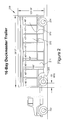
- FIG. 1 is a depiction of a side-bay delivery vehicle according to an embodiment of the present subject matter.
- an exemplary side-bay delivery vehicle 100 may include ten bays 110, five bays on one side of the vehicle 100 and five bays (not shown) on the opposite side of the vehicle 100. Any one or several of these bays may be standard, insulated, isolated and/or access thereto may be achieved via a side roll-up or swing door. While not shown, and dependent upon the configuration thereof, any number of these bays 110 may be accessible via a rear roll-up or swing door. Table 2 below provides typical capacity, payload and weight data for such a vehicle 100.
- each bay 110 may be approximately fifty two inches wide with eight bays 111 having a height of approximately eighty two inches and the two bays 112 overlying the rear axle 104 having an approximate height of fifty nine inches.
- a typical body weight of the vehicle 100 may be 3,180 pounds and may provide a capacity of 1,170 cases of 12-oz cans thereby resulting in a payload of approximately 25,230 lbs.
- the weight distribution of a fully loaded vehicle 100 between the front axle 102 and rear axle 104 may be approximately 32.6% on the front axle 102 and 67.4% on the rear axle 104.
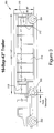
- FIG. 2 is a depiction of a side-bay delivery vehicle according to another embodiment of the present subject matter.
- an exemplary side-bay delivery vehicle 200 may include sixteen bays 210, eight bays on one side of the vehicle 200 and eight bays (not shown) on the opposite side of the vehicle 200. Any one or several of these bays may be standard, insulated, isolated and/or access thereto may be achieved via a side roll-up or swing door. While not shown, and dependent upon the configuration thereof, any number of these bays 210 may be accessible via a rear roll-up or swing door. Table 3 below provides typical capacity, payload and weight data for such a vehicle 200.
- each bay 210 may be approximately forty inches wide with two bays 211 having a height of approximately one hundred inches and the remaining fourteen bays 214 having an approximate height of sixty eight inches.
- a typical body weight of the vehicle 200 may be 9,872 pounds and may provide a capacity of 1,512 cases of 12-oz cans thereby resulting in a payload of approximately 32,552 lbs.
- the weight distribution of a fully loaded vehicle 200 between the front axle 202, drive axle(s) 203 and rear axle(s) 204 may be approximately 15.4% on the front axle 202, 42.1% on the drive axle(s) 203 and 42.5% on the rear axle(s) 204.
- FIG. 3 is a depiction of a side-bay delivery vehicle according to a further embodiment of the present subject matter.
- an exemplary side-bay delivery vehicle 300 may include sixteen bays 310, eight bays on one side of the vehicle 300 and eight bays (not shown) on the opposite side of the vehicle 300. Any one or several of these bays may be standard, insulated, isolated and/or access thereto may be achieved via a side roll-up or swing door. While not shown, and dependent upon the configuration thereof, any number of these bays 310 may be accessible via a rear roll-up or swing door. Table 4 below provides typical capacity, payload and weight data for such a vehicle 300.
- each bay 310 may be approximately forty inches wide with four bays 312 having a height of approximately thirteen inches and the remaining twelve bays 314 having an approximate height of eighty two inches.
- a typical body weight of the vehicle 300 may be 9,033 pounds and may provide a capacity of 1,472 cases of 12-oz cans thereby resulting in a payload of approximately 31,712 lbs.
- the weight distribution of a fully loaded vehicle 300 between the front axle 302, drive axle(s) 303 and rear axle(s) 304 may be approximately 14.3% on the front axle 302, 41.3% on the drive axle(s) 303 and 44.4% on the rear axle(s) 304.
- the tandem axle may have 3 full height bays, 3 short bays and 1 1 ⁇ 2 width bay over the king pin plate on each side. 14 bay This trailer may have 4 full height bays and 3 short bays on each side. 14.5 bay This trailer may have 5 full height bays, 2 short bays and 1 half bay on each side. 16 bay May come in either single or tandem axle.
- the single axle is a common trailer in use today.
- the tandem axles may have 4 full height bays and 4 short bays on each side.
- 18 bay May come in either single or tandem axle.
- the single axle may have 6 full height bays and 3 short bays on each side.
- the tandem axle may have 5 full height bays and 4 short bays on each side. 20 bay Tandem axle.
- This trailer may have 6 full height bays and 4 short bays on each side. 22 bay Tandem axle. This trailer may have 7 full height bays and 4 short bays on each side. 24 bay Tandem axle. This trailer may have 7 full height bays and 5 short bays on each side. Stretch These trailers may come in different sizes (16 bay most common). They may generally be modified by extending the king pin about 12 inches forward to allow enough clearance to convert one of the two short bays over the king pin plate in a standard trailer to a full height bay. Combination These trailers generally have one of the following: multiple bay widths, both roll-up and swing doors, and standard and insulated/isolated bays.
- the width of exemplary bays may vary, e.g. , from less than forty inches to over fifty two inches at full width and that certain exemplary vehicles may also provide multiple bay widths and/or may provide bays with fractions or multiples of full width bays.
- the height of exemplary bays may vary, e.g. , from less than eighty two inches to over ninety inches at full height and that certain exemplary vehicles may also provide multiple bay heights and/or may provide bays with fractions or multiples of full height bays.
- the depth of exemplary bays may vary, e.g.
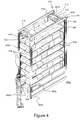
- Figure 4 is a perspective view of one embodiment of the present subject matter.
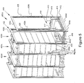
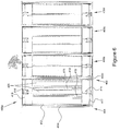
- Figure 5 is a perspective view of another embodiment of the present subject matter.
- Figure 6 is a top plan view of the embodiment of Figure 5 .
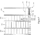
- Figure 7 is a front plan view of the embodiment of Figure 5 .
- Figure 8 is an additional perspective view of the embodiment of Figure 5 .
- vehicular walls have been omitted in Figures 4-8 .
- Figures 5-8 depict embodiments having multiple frames and/or bays 400a-400d
- Figure 4 depicts an embodiment having a single bay 400a.
- any of the exemplary delivery vehicles depicted in Figures 1-3 and/or described above may include in any one or several of its respective bays a first rectangular frame 402 and a second rectangular frame 404.
- these rectangular frames 402, 404 may be substantially parallel and oppose and face the other and may each include two vertical members 402a, 402b, 404a, 404b, respectively, and may each include two horizontal members 402c, 402d, 404c, 404d, respectively.
- adjacent bays may or may not share a rectangular frame.
- Exemplary bays may be standard bays, insulated bays or isolated bays depending upon the desired design. Further, it is envisioned that these rectangular frames may be collapsible upon and/or telescope with the other rectangular frames. In such an embodiment, the rectangular frames may be movably affixed to a track mechanism whereby once product in a first set of frames or a bay has been depleted, an adjacent bay or frame may collapse upon the first frame and the product in the adjacent frame(s) delivered as discussed further below.
- any or each of the vertical members 402a, 402b, 404a, 404b may include a linear gear 406 affixed thereto.
- the linear gear 406 may extend along any portion or the entire length of the respective vertical member.
- Confined within the two rectangular frames 402, 404 may be a holding structure 410.
- the holding structure 410 is preferably engaged by both of the rectangular frames 402, 404 and may include a horizontal frame 412 or tray adjacent each of the vertical members 402a, 402b, 404a, 404b of the rectangular frames 402, 404 at corners of the horizontal frame 412.
- any number of the horizontal frames 412 may be partitioned into a number of horizontal bins 413.
- the horizontal frame 412 may include three bins. Additional embodiments of the horizontal frame 412 may include one, two, four or more bins.
- the holding structure 410 may also include one or more motors 414, 415 that engages a respective shaft 416, 417.
- the motor(s) 414, 415 may be removably affixed to a motor holding assembly 440, 441 which is affixed to an uppermost horizontal frame 412 or tray.
- Exemplary motors may be, but are not limited to electric motors, hydraulic motors and the like.
- Each end of the shaft 416, 417 may accept a gear 419 which rotatably engages the linear gear 406 of a respective and/or adjacent vertical member 402a, 402b, 404a, 404b.
- the shaft 416, 417 may extend through perforations or holes in a portion of the assembly 440, 441.
- each frame may include an affixed guide pin or rod 460, the distal end thereof 462 being bulbous or having a stop.
- the guide pin 460 may extend through holes 464 in each frame 412 contained within the same bay 400a.
- the motor(s) 414, 415 is actuated to increase, for example, the height of the holding structure 410, the upper most frame increases its height, engaging the stop at the distal end 462 of the rod 460 affixed to a second frame immediately below the upper most frame. As this second frame also increases its height, it will eventually engage the stop of the distal end 462 of another rod 460, this another rod 460 affixed to a third frame immediately below the second frame, and so forth. The same will hold true but in reverse when the frames collapse upon each other.
- the length of the guide pins 460 are adjustable to alter the final height or distance between adjacent frames, and the size of the stops or bulbous distal ends 462 of the pins 460 may vary to ensure that only a predetermined frame engage or allow the raising/lowering of a respective frame.
- Confined within the two rectangular frames 402, 404 may also be one or more belts 420.
- the belt(s) 420 may be positioned between the lower horizontal members 402d, 404d of the two rectangular frames 402, 404.
- a corresponding number of belts 420 would be positioned between the respective frames 402, 404.
- Figure 4 provides a depiction of three bins 413 with the respective horizontal frame 412 and a corresponding number of belts 420, one for each bin. This example, however, should not limit the scope of the claims appended herewith as it is envisioned that any number of belts may be utilized for any number of respective horizontal frames 412 and their respective bins 413.
- operation of the motor(s) 414, 415 may provide vertical movement of the holding structure 410 within the confines of the two rectangular frames 402, 404, and operation of the belt(s) 420 may provide a lateral or horizontal movement within the confines of the rectangular frames 402, 404 and therefore movement of product or cargo from the respective horizontal frame 412 or bin 413 to an individual.
- the movement of each belt 420 may be independent of the others and such movement may be effected by a motor, electric, hydraulic or otherwise. It is envisioned that operation of the motors 414, 415 and hence the vertical movement be automated or manual. Additionally, it is envisioned that operation of the belt(s) 420 also be automated or manual.
- the holding structure may be collapsed (automatically or manually), bringing the next level of product to the lower level.
- embodiments of the present subject matter have been described as utilizing the holding structure above, the claims appended herewith should not be so limited as other mechanical assemblies are also envisioned such as pulley mechanisms, chain or chained mechanisms, hydraulic mechanisms and lifts, and so forth.
- access to the bays 400a-400d in Figures 4-8 may be interpreted as a side-access
- the claims appended herewith should not be so limited as an embodiment having one or more bays may be included in a vehicle having only rear-access to the cargo therein. Of course, access to the bays 400a-400d may be via a roll-up or swing door.
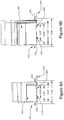
- Figures 9A and 9B are illustrations of horizontal frames according to embodiments of the present subject matter.
- an exemplary horizontal frame 412 or tray may include ridges or raised portions 910 to keep cargo or product 920 situated on the horizontal frame 412.
- a separating ridge 912 may be provided between bins 413 to keep product in adjacent bins from interfering with each other.
- the horizontal frame 412 and separate bins 413 may provide an opening 930 in which a belt 420 can contact product 920 situated on the horizontal frame 412 or bin 413 and provide lateral movement of such product 920.
- the width of the opening 930 may be adjustable to accommodate product ( e.g. , cases and the like) of varying dimensions.
- the width of the opening 930 may also be fixed and not adjustable.
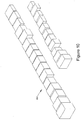
- Figure 10 is a perspective view of exemplary dimensions of product 920 or cargo embodiments of the present subject matter may accommodate. With reference to Figures 9A, 9B and 10 , it is apparent that through the adjustment of the width opening 930, embodiments of the present subject matter may accept, accommodate and deliver to an individual product 920 or cargo having a wide variety of dimensions.
- the product 920 illustrated in Figures 9A, 9B and 10 are exemplary only and should not limit the scope of the claims appended herewith.
- Table 6 below provides common dimensions for certain beverage products utilized in the industry.
- 24pk can 172 2.5 23.7 10.8 16.1 Lite 12pk ln2 166 2.4 26.2 10.5 15.5 High Life 12pk ln2 165 2.4 28.6 10.5 15.5 Lite 18pk can 162 2.4 31.0 7.9 15.6 Lite 20/12 lnnr 160 2.4 33.3 10.3 12.9 Lite Fridge 12pk can 138 2.0 35.4 10.8 16.1 Best Ice 24pk can 125 1.9 37.2 10.8 16.1 Red Bull Energy Drink 123 1.8 39.1 9.0 13.0 Corona 6pk ln/4 122 1.8 40.9 11.0 16.0 High Life 40 oz nr 12 106 1.6 42.4 11.8 15.4 Best Ice 12pk can 2 96 1.4 43.8 7.9 10.5 Icehouse 24oz can/12 88 1.3 45.1 9.0 12.0 Best 24pk cans 85 1.3 46.4 10.8 16.1 Icehouse 24pk can 81 1.2 47.6 10.8 16.1 Icehouse 12pk ln 2 74 1.1 48.7
- 12pk can 2 70 1.0 50.8 7.9 10.5 Icehouse 18/12 lnnr 69 1.0 51.8 7.8 15.0 High Life Fridge pack (2/12) 67 1.0 52.8 10.8 16.1 Canada Dry Ginger Ale 8/2L 66 1.0 53.8 10.0 19.0 High Life 6pk ln 4 65 1.0 54.7 10.5 15.5 Icehouse 6pk ln 63 0.9 55.7 10.5 15.5
- FIG 11 is a block diagram of one embodiment of the present subject matter.
- a method 1100 for loading products in a vehicle and/or delivering products to an individual or customer may include at step 1110, operating one or more mechanisms and at step 1120 imparting vertical and lateral motion to a product within a bay of the vehicle using the one or more mechanisms.
- Exemplary vehicles may include any of the aforementioned and described delivery vehicles and may include at least one bay having two exemplary rectangular frames as described above, each frame with two horizontal members and two vertical members and each frame opposing and facing the other.
- the bay may also include an exemplary holding structure as described above engaged by both of the rectangular frames, the structure comprising one or more horizontal trays having the product contained thereon.
- one of the mechanisms may be a motor, the operation of which would collapse or telescope the one or more horizontal trays in a vertical motion.
- one of the mechanisms may be a belt, the operation of which would laterally move the product from the one or more horizontal trays.
- this lateral and/or vertical movement may be automatic or manual.
- FIG 12 is a block diagram of another embodiment of the present subject matter.
- a method 1200 for tracking the delivery of products to a customer may include at step 1210 assigning a code to identify a product and at step 1220 loading the product into a delivery vehicle.
- the vehicle may include one or more delivery bays having vertical frames carrying a holding structure and having a belt assembly as described above.
- Exemplary codes may be, but are not limited to a Stock-Keeping Unit (SKU), an Universal Product Code (UPC), an European Article Number (EAN), a Global Trade Item Number (GTIN), Price look-up (PLU) code, and an Australian Product Number (APN).
- SKU Stock-Keeping Unit
- UPC Universal Product Code
- EAN European Article Number
- GTIN Global Trade Item Number
- PLU Price look-up
- the method 1200 may further include at step 1230 unloading the product from the delivery vehicle and at step 1240 tracking the delivery of the product using the code.
- steps 1220 or 1230 may include providing vertical movement of the product using the holding structure and providing lateral movement using the belt assembly with the one or more delivery bays of the vehicle.
- either or both of the vertical or horizontal movement may be automatic or manual.
- any such automated or automatic movement may be a function of the assigned code.
- an individual or operator may, upon unloading (or loading) product within a bay in the vehicle, input into a handheld device or device affixed to the vehicle, a specific SKU or series of SKUs.
- the device would communicate wirelessly or via a wired connection with a database or memory unit and the location of the product(s) corresponding to the SKU or series of SKUs would be found. Depending upon such location, the product(s) would then be delivered (or loaded), automatically or manually, to (or from) the individual or operator in accordance with the vertical and lateral movement described in previous paragraphs.
- embodiments of the present subject matter may overcome the limitations in the current delivery industry (e.g. , delivering product for the beverage, dairy, vending machine, bakery, snack food, etc., industries) and provide a dynamic solution that keeps pace with and accommodates growing product portfolios and/or package dimensions and increasing customer demands.
- Other aspects of embodiments of the present subject matter are to improve performance, increase delivery vehicle capacity, maximize cubic space available on a delivery vehicle, and reduce cost of product deliveries by providing a material change to the design of delivery vehicles.
- embodiments of the present subject matter may provide products to a delivery driver at ground or waist level in a forward most position, thus minimizing the number of door openings/closings and eliminating the excessive strain and stress upon the delivery driver.
Landscapes
- Engineering & Computer Science (AREA)
- Business, Economics & Management (AREA)
- Transportation (AREA)
- Mechanical Engineering (AREA)
- Economics (AREA)
- Health & Medical Sciences (AREA)
- Public Health (AREA)
- Marketing (AREA)
- Tourism & Hospitality (AREA)
- Human Resources & Organizations (AREA)
- Development Economics (AREA)
- Operations Research (AREA)
- Quality & Reliability (AREA)
- Strategic Management (AREA)
- Entrepreneurship & Innovation (AREA)
- Physics & Mathematics (AREA)
- General Business, Economics & Management (AREA)
- General Physics & Mathematics (AREA)
- Theoretical Computer Science (AREA)
- Management, Administration, Business Operations System, And Electronic Commerce (AREA)
- Warehouses Or Storage Devices (AREA)
- Handcart (AREA)
Applications Claiming Priority (3)
| Application Number | Priority Date | Filing Date | Title |
|---|---|---|---|
| US13/187,871 US9073470B2 (en) | 2011-07-21 | 2011-07-21 | Ergonomically improved delivery vehicle and method |
| EP12814322.9A EP2734412B1 (de) | 2011-07-21 | 2012-07-19 | Ergonomisch verbesserter verabreichungsträger und verfahren dafür |
| PCT/US2012/047316 WO2013013000A2 (en) | 2011-07-21 | 2012-07-19 | Ergonomically improved delivery vehicle and method |
Related Parent Applications (1)
| Application Number | Title | Priority Date | Filing Date |
|---|---|---|---|
| EP12814322.9A Division EP2734412B1 (de) | 2011-07-21 | 2012-07-19 | Ergonomisch verbesserter verabreichungsträger und verfahren dafür |
Publications (2)
| Publication Number | Publication Date |
|---|---|
| EP3552876A1 true EP3552876A1 (de) | 2019-10-16 |
| EP3552876B1 EP3552876B1 (de) | 2020-12-02 |
Family
ID=47556502
Family Applications (2)
| Application Number | Title | Priority Date | Filing Date |
|---|---|---|---|
| EP19178113.7A Active EP3552876B1 (de) | 2011-07-21 | 2012-07-19 | Ergonomisch verbesserter verabreichungsträger und verfahren dafür |
| EP12814322.9A Active EP2734412B1 (de) | 2011-07-21 | 2012-07-19 | Ergonomisch verbesserter verabreichungsträger und verfahren dafür |
Family Applications After (1)
| Application Number | Title | Priority Date | Filing Date |
|---|---|---|---|
| EP12814322.9A Active EP2734412B1 (de) | 2011-07-21 | 2012-07-19 | Ergonomisch verbesserter verabreichungsträger und verfahren dafür |
Country Status (5)
| Country | Link |
|---|---|
| US (2) | US9073470B2 (de) |
| EP (2) | EP3552876B1 (de) |
| JP (1) | JP6030129B2 (de) |
| CA (1) | CA2842428C (de) |
| WO (1) | WO2013013000A2 (de) |
Families Citing this family (20)
| Publication number | Priority date | Publication date | Assignee | Title |
|---|---|---|---|---|
| DE102015111033A1 (de) * | 2015-07-08 | 2017-01-12 | Deutsche Post Ag | Vorrichtung und Verfahren zur flexiblen Abholung und/oder Einlieferung einer Sendung |
| CN105083092B (zh) * | 2015-07-10 | 2017-04-19 | 芜湖市海洋物流有限公司 | 一种物流用自动化运输装卸车 |
| CN105059403A (zh) * | 2015-07-31 | 2015-11-18 | 谢子聪 | 用于电动乘用车动力电池更换的移动加电车的厢体系统 |
| CN105236162B (zh) * | 2015-09-06 | 2017-11-24 | 巨石集团有限公司 | 一种托盘自动卸车装置 |
| WO2017120090A1 (en) * | 2016-01-06 | 2017-07-13 | Russell David Wayne | System and method for autonomous shelving units |
| CN106570667B (zh) * | 2016-10-25 | 2020-08-21 | 北京印刷学院 | 一种基于车-快递柜-无人机的快递配送方法 |
| CN106541880B (zh) * | 2016-10-25 | 2019-04-12 | 北京印刷学院 | 一种智能运输装置 |
| CN106570666B (zh) * | 2016-10-25 | 2020-08-21 | 北京印刷学院 | 一种应用于快递运输装置的智能控制系统 |
| CN106429162A (zh) * | 2016-12-08 | 2017-02-22 | 成都天航智虹企业管理咨询有限公司 | 一种配送箱 |
| CN106671853A (zh) * | 2016-12-30 | 2017-05-17 | 重庆大学 | 一种快递运载装置 |
| WO2018231756A1 (en) * | 2017-06-16 | 2018-12-20 | Walmart Apollo, Llc | Systems and methods for loading totes using hydraulic lifts |
| NO347820B1 (en) | 2018-01-09 | 2024-04-08 | Autostore Tech As | Automated storage and retrieval system, a container handling vehicle which can operate on an automated storage and retrieval system and a method of operating an automated storage and retrieval system |
| CN107972552A (zh) * | 2018-01-15 | 2018-05-01 | 钦州学院 | 一种快速装卸蜂箱的养蜂车 |
| CN108791925A (zh) * | 2018-06-15 | 2018-11-13 | 南通嗨森无人机科技有限公司 | 一种民用快递载重无人机 |
| WO2020102900A1 (en) * | 2018-11-20 | 2020-05-28 | Advanced Intelligent Systems Inc. | Systems, methods, and storage units for article transport and storage |
| CO2019010919A1 (es) * | 2019-10-01 | 2021-04-08 | Pontificia Univ Javeriana | Mecanismo de carga y descarga de materiales para un contenedor |
| EP3974251B1 (de) * | 2020-09-25 | 2023-11-29 | Jungheinrich Aktiengesellschaft | Zustellfahrzeug |
| KR20220045637A (ko) * | 2020-10-06 | 2022-04-13 | 현대자동차주식회사 | 카고의 택배물 적재구조 및 적재 방법 |
| DE102021133322A1 (de) | 2021-12-15 | 2023-06-15 | Ford Global Technologies, Llc | Automobil mit Regal im Laderaum |
| DE102022125465A1 (de) * | 2022-10-04 | 2024-04-04 | Ford Global Technologies Llc | Regalsystem und Verfahren zum Betreiben eines Regals |
Citations (9)
| Publication number | Priority date | Publication date | Assignee | Title |
|---|---|---|---|---|
| US2779487A (en) | 1955-01-14 | 1957-01-29 | Francis D Harris | Vehicle mounted handling device for pallet stacks |
| US2832636A (en) | 1956-02-06 | 1958-04-29 | Trailmoblie Inc | Elevating system for trailer center deck |
| US3929371A (en) | 1974-07-01 | 1975-12-30 | Louis J Gibson | Support means for stacks of articles |
| US4139109A (en) | 1977-07-29 | 1979-02-13 | Murphy Robert P | Load lift assembly for trucks |
| US4701086A (en) | 1986-02-10 | 1987-10-20 | Atlantis Projects Inc. | Transportation van having load elevating platform located therein |
| DE8907876U1 (de) * | 1989-06-28 | 1989-08-31 | Karosseriebau Heinrichs GmbH, 4720 Beckum | Fahrbarer Warenbehälter |
| US5092721A (en) | 1988-11-28 | 1992-03-03 | Coterie, Ltd. | Double drop trailer with two lifts |
| US5931262A (en) | 1995-06-07 | 1999-08-03 | Greenlaw; Robert J. | Delivery vehicle with multi-tier storage of cargo |
| DE19809291A1 (de) * | 1998-03-05 | 1999-09-09 | Unterberg | Fahrzeug, insbesondere Transportfahrzeug zur Aufnahme von Gegenständen |
Family Cites Families (15)
| Publication number | Priority date | Publication date | Assignee | Title |
|---|---|---|---|---|
| DE2340692C3 (de) * | 1973-08-10 | 1982-11-04 | Maschinenfabrik Fahr Ag Gottmadingen, 7702 Gottmadingen | Fahrbares Gerät zum selbsttätigen Aufnehmen, Speichern und Abgeben von Stückgütern, insbesondere Heu- oder Strohballen |
| US4033620A (en) * | 1975-09-04 | 1977-07-05 | Blake Robert L | Bee hive carrier and transport means |
| US4294332A (en) * | 1979-04-13 | 1981-10-13 | Ready Delbert L | Scaffold with gear drive |
| GB8617088D0 (en) | 1986-07-14 | 1986-08-20 | Hydraroll Ltd | Load handling system |
| US5054295A (en) * | 1990-08-21 | 1991-10-08 | Goulooze Gene D | Transport with variable volume, independently cooled compartments |
| JPH04110243A (ja) * | 1990-08-30 | 1992-04-10 | Anritsu Corp | 荷物用車両の荷台 |
| JP2961294B2 (ja) * | 1994-06-30 | 1999-10-12 | 良三 太田 | エレベーター |
| JPH0812092A (ja) * | 1994-07-04 | 1996-01-16 | Kouritsu Gijutsu Kenkyusho:Kk | 車両積載物品収納装置および物品収納・排出方法 |
| US6033002A (en) * | 1995-07-26 | 2000-03-07 | Clare; Scott | Collapsible material carrier and hidden storage system for vehicle beds |
| JP2000296995A (ja) * | 1999-04-08 | 2000-10-24 | Toho Kenzai:Kk | 上下動積みおろし装置 |
| ITBO20020728A1 (it) * | 2002-11-19 | 2004-05-20 | Resta Srl | Dispositivo per l'immagazzinamento temporaneo di manufatti, |
| US7036861B2 (en) * | 2003-02-10 | 2006-05-02 | Steffens Enterprises, Inc. | Cargo compartment organizer |
| EP1741594B2 (de) | 2005-07-07 | 2014-11-26 | Omar-S.R.L. | Vorrichtung und Verfahren zur Förderung von Paletten |
| JP3133872U (ja) * | 2007-05-15 | 2007-07-26 | 住友金属物流株式会社 | 長尺品の段積み輸送用保定装置 |
| US9096375B2 (en) * | 2009-04-10 | 2015-08-04 | Symbotic, LLC | Storage and retrieval system |
-
2011
- 2011-07-21 US US13/187,871 patent/US9073470B2/en active Active
-
2012
- 2012-07-19 EP EP19178113.7A patent/EP3552876B1/de active Active
- 2012-07-19 CA CA2842428A patent/CA2842428C/en active Active
- 2012-07-19 EP EP12814322.9A patent/EP2734412B1/de active Active
- 2012-07-19 WO PCT/US2012/047316 patent/WO2013013000A2/en not_active Ceased
- 2012-07-19 JP JP2014521756A patent/JP6030129B2/ja active Active
-
2015
- 2015-06-01 US US14/727,387 patent/US10507754B2/en active Active
Patent Citations (9)
| Publication number | Priority date | Publication date | Assignee | Title |
|---|---|---|---|---|
| US2779487A (en) | 1955-01-14 | 1957-01-29 | Francis D Harris | Vehicle mounted handling device for pallet stacks |
| US2832636A (en) | 1956-02-06 | 1958-04-29 | Trailmoblie Inc | Elevating system for trailer center deck |
| US3929371A (en) | 1974-07-01 | 1975-12-30 | Louis J Gibson | Support means for stacks of articles |
| US4139109A (en) | 1977-07-29 | 1979-02-13 | Murphy Robert P | Load lift assembly for trucks |
| US4701086A (en) | 1986-02-10 | 1987-10-20 | Atlantis Projects Inc. | Transportation van having load elevating platform located therein |
| US5092721A (en) | 1988-11-28 | 1992-03-03 | Coterie, Ltd. | Double drop trailer with two lifts |
| DE8907876U1 (de) * | 1989-06-28 | 1989-08-31 | Karosseriebau Heinrichs GmbH, 4720 Beckum | Fahrbarer Warenbehälter |
| US5931262A (en) | 1995-06-07 | 1999-08-03 | Greenlaw; Robert J. | Delivery vehicle with multi-tier storage of cargo |
| DE19809291A1 (de) * | 1998-03-05 | 1999-09-09 | Unterberg | Fahrzeug, insbesondere Transportfahrzeug zur Aufnahme von Gegenständen |
Also Published As
| Publication number | Publication date |
|---|---|
| EP2734412A2 (de) | 2014-05-28 |
| JP6030129B2 (ja) | 2016-11-24 |
| CA2842428C (en) | 2022-01-04 |
| US20150336497A1 (en) | 2015-11-26 |
| EP3552876B1 (de) | 2020-12-02 |
| US9073470B2 (en) | 2015-07-07 |
| CA2842428A1 (en) | 2013-01-24 |
| WO2013013000A3 (en) | 2013-04-18 |
| EP2734412B1 (de) | 2019-06-05 |
| WO2013013000A2 (en) | 2013-01-24 |
| US10507754B2 (en) | 2019-12-17 |
| US20130024392A1 (en) | 2013-01-24 |
| EP2734412A4 (de) | 2015-11-18 |
| JP2014524869A (ja) | 2014-09-25 |
Similar Documents
| Publication | Publication Date | Title |
|---|---|---|
| EP3552876B1 (de) | Ergonomisch verbesserter verabreichungsträger und verfahren dafür | |
| US3879053A (en) | Mobile display cart | |
| US9580097B2 (en) | Apparatus and method for efficiently transporting various articles | |
| US20200231381A1 (en) | Object handling system and method | |
| US3628807A (en) | Mobile merchandiser cart | |
| US9061719B2 (en) | Transport trailer and method | |
| US20240286841A1 (en) | Warehousing system and control method thereof | |
| US20170225601A1 (en) | Vehicle insert and method of vehicle loading and unloading | |
| US12134518B2 (en) | Transport rack cartridge (TRC) | |
| US4093086A (en) | Warehousing system | |
| EP1931552B1 (de) | Vorrichtung für den transport von produkten in kisten oder behältern | |
| US20170210561A1 (en) | Palletized storage and distribution system | |
| US10889407B2 (en) | Convertible pallet for use as a cart | |
| US3861704A (en) | Standard bulk cart | |
| US20090245991A1 (en) | Transport Trailer and Method | |
| JP2000159117A (ja) | 入庫又は出庫作業用の台車 | |
| US12145411B2 (en) | Pallet train | |
| US20240409313A1 (en) | An assembly, a storage module and an automated storage and retrieval system | |
| Shaffer et al. | Unloading and receiving produce in retail food stores | |
| RU28471U1 (ru) | Торговое оборудование (варианты), контейнер для товаров | |
| WO2023107424A2 (en) | Mobile package transfer rack | |
| Bouma | Methods of increasing productivity in modern grocery warehouses | |
| Brown | Manual Materials Handling in the Frozen Food Delivery Industry: Depalletizing | |
| GB2519064A (en) | Twin container box van | |
| GB2640248A (en) | Goods collecting apparatus |
Legal Events
| Date | Code | Title | Description |
|---|---|---|---|
| PUAI | Public reference made under article 153(3) epc to a published international application that has entered the european phase |
Free format text: ORIGINAL CODE: 0009012 |
|
| STAA | Information on the status of an ep patent application or granted ep patent |
Free format text: STATUS: THE APPLICATION HAS BEEN PUBLISHED |
|
| AC | Divisional application: reference to earlier application |
Ref document number: 2734412 Country of ref document: EP Kind code of ref document: P |
|
| AK | Designated contracting states |
Kind code of ref document: A1 Designated state(s): AL AT BE BG CH CY CZ DE DK EE ES FI FR GB GR HR HU IE IS IT LI LT LU LV MC MK MT NL NO PL PT RO RS SE SI SK SM TR |
|
| STAA | Information on the status of an ep patent application or granted ep patent |
Free format text: STATUS: REQUEST FOR EXAMINATION WAS MADE |
|
| 17P | Request for examination filed |
Effective date: 20200109 |
|
| RBV | Designated contracting states (corrected) |
Designated state(s): AL AT BE BG CH CY CZ DE DK EE ES FI FR GB GR HR HU IE IS IT LI LT LU LV MC MK MT NL NO PL PT RO RS SE SI SK SM TR |
|
| GRAP | Despatch of communication of intention to grant a patent |
Free format text: ORIGINAL CODE: EPIDOSNIGR1 |
|
| STAA | Information on the status of an ep patent application or granted ep patent |
Free format text: STATUS: GRANT OF PATENT IS INTENDED |
|
| INTG | Intention to grant announced |
Effective date: 20200811 |
|
| GRAS | Grant fee paid |
Free format text: ORIGINAL CODE: EPIDOSNIGR3 |
|
| GRAA | (expected) grant |
Free format text: ORIGINAL CODE: 0009210 |
|
| STAA | Information on the status of an ep patent application or granted ep patent |
Free format text: STATUS: THE PATENT HAS BEEN GRANTED |
|
| AC | Divisional application: reference to earlier application |
Ref document number: 2734412 Country of ref document: EP Kind code of ref document: P |
|
| AK | Designated contracting states |
Kind code of ref document: B1 Designated state(s): AL AT BE BG CH CY CZ DE DK EE ES FI FR GB GR HR HU IE IS IT LI LT LU LV MC MK MT NL NO PL PT RO RS SE SI SK SM TR |
|
| REG | Reference to a national code |
Ref country code: GB Ref legal event code: FG4D |
|
| REG | Reference to a national code |
Ref country code: AT Ref legal event code: REF Ref document number: 1340560 Country of ref document: AT Kind code of ref document: T Effective date: 20201215 Ref country code: CH Ref legal event code: EP |
|
| REG | Reference to a national code |
Ref country code: IE Ref legal event code: FG4D |
|
| REG | Reference to a national code |
Ref country code: DE Ref legal event code: R096 Ref document number: 602012073589 Country of ref document: DE |
|
| REG | Reference to a national code |
Ref country code: CH Ref legal event code: NV Representative=s name: E. BLUM AND CO. AG PATENT- UND MARKENANWAELTE , CH |
|
| PG25 | Lapsed in a contracting state [announced via postgrant information from national office to epo] |
Ref country code: GR Free format text: LAPSE BECAUSE OF FAILURE TO SUBMIT A TRANSLATION OF THE DESCRIPTION OR TO PAY THE FEE WITHIN THE PRESCRIBED TIME-LIMIT Effective date: 20210303 Ref country code: NO Free format text: LAPSE BECAUSE OF FAILURE TO SUBMIT A TRANSLATION OF THE DESCRIPTION OR TO PAY THE FEE WITHIN THE PRESCRIBED TIME-LIMIT Effective date: 20210302 Ref country code: FI Free format text: LAPSE BECAUSE OF FAILURE TO SUBMIT A TRANSLATION OF THE DESCRIPTION OR TO PAY THE FEE WITHIN THE PRESCRIBED TIME-LIMIT Effective date: 20201202 Ref country code: RS Free format text: LAPSE BECAUSE OF FAILURE TO SUBMIT A TRANSLATION OF THE DESCRIPTION OR TO PAY THE FEE WITHIN THE PRESCRIBED TIME-LIMIT Effective date: 20201202 |
|
| REG | Reference to a national code |
Ref country code: NL Ref legal event code: MP Effective date: 20201202 |
|
| REG | Reference to a national code |
Ref country code: AT Ref legal event code: MK05 Ref document number: 1340560 Country of ref document: AT Kind code of ref document: T Effective date: 20201202 |
|
| PG25 | Lapsed in a contracting state [announced via postgrant information from national office to epo] |
Ref country code: BG Free format text: LAPSE BECAUSE OF FAILURE TO SUBMIT A TRANSLATION OF THE DESCRIPTION OR TO PAY THE FEE WITHIN THE PRESCRIBED TIME-LIMIT Effective date: 20210302 Ref country code: SE Free format text: LAPSE BECAUSE OF FAILURE TO SUBMIT A TRANSLATION OF THE DESCRIPTION OR TO PAY THE FEE WITHIN THE PRESCRIBED TIME-LIMIT Effective date: 20201202 Ref country code: LV Free format text: LAPSE BECAUSE OF FAILURE TO SUBMIT A TRANSLATION OF THE DESCRIPTION OR TO PAY THE FEE WITHIN THE PRESCRIBED TIME-LIMIT Effective date: 20201202 Ref country code: PL Free format text: LAPSE BECAUSE OF FAILURE TO SUBMIT A TRANSLATION OF THE DESCRIPTION OR TO PAY THE FEE WITHIN THE PRESCRIBED TIME-LIMIT Effective date: 20201202 |
|
| PG25 | Lapsed in a contracting state [announced via postgrant information from national office to epo] |
Ref country code: NL Free format text: LAPSE BECAUSE OF FAILURE TO SUBMIT A TRANSLATION OF THE DESCRIPTION OR TO PAY THE FEE WITHIN THE PRESCRIBED TIME-LIMIT Effective date: 20201202 Ref country code: HR Free format text: LAPSE BECAUSE OF FAILURE TO SUBMIT A TRANSLATION OF THE DESCRIPTION OR TO PAY THE FEE WITHIN THE PRESCRIBED TIME-LIMIT Effective date: 20201202 |
|
| REG | Reference to a national code |
Ref country code: LT Ref legal event code: MG9D |
|
| PG25 | Lapsed in a contracting state [announced via postgrant information from national office to epo] |
Ref country code: PT Free format text: LAPSE BECAUSE OF FAILURE TO SUBMIT A TRANSLATION OF THE DESCRIPTION OR TO PAY THE FEE WITHIN THE PRESCRIBED TIME-LIMIT Effective date: 20210405 Ref country code: RO Free format text: LAPSE BECAUSE OF FAILURE TO SUBMIT A TRANSLATION OF THE DESCRIPTION OR TO PAY THE FEE WITHIN THE PRESCRIBED TIME-LIMIT Effective date: 20201202 Ref country code: LT Free format text: LAPSE BECAUSE OF FAILURE TO SUBMIT A TRANSLATION OF THE DESCRIPTION OR TO PAY THE FEE WITHIN THE PRESCRIBED TIME-LIMIT Effective date: 20201202 Ref country code: EE Free format text: LAPSE BECAUSE OF FAILURE TO SUBMIT A TRANSLATION OF THE DESCRIPTION OR TO PAY THE FEE WITHIN THE PRESCRIBED TIME-LIMIT Effective date: 20201202 Ref country code: SM Free format text: LAPSE BECAUSE OF FAILURE TO SUBMIT A TRANSLATION OF THE DESCRIPTION OR TO PAY THE FEE WITHIN THE PRESCRIBED TIME-LIMIT Effective date: 20201202 Ref country code: SK Free format text: LAPSE BECAUSE OF FAILURE TO SUBMIT A TRANSLATION OF THE DESCRIPTION OR TO PAY THE FEE WITHIN THE PRESCRIBED TIME-LIMIT Effective date: 20201202 Ref country code: CZ Free format text: LAPSE BECAUSE OF FAILURE TO SUBMIT A TRANSLATION OF THE DESCRIPTION OR TO PAY THE FEE WITHIN THE PRESCRIBED TIME-LIMIT Effective date: 20201202 |
|
| PG25 | Lapsed in a contracting state [announced via postgrant information from national office to epo] |
Ref country code: AT Free format text: LAPSE BECAUSE OF FAILURE TO SUBMIT A TRANSLATION OF THE DESCRIPTION OR TO PAY THE FEE WITHIN THE PRESCRIBED TIME-LIMIT Effective date: 20201202 |
|
| REG | Reference to a national code |
Ref country code: DE Ref legal event code: R097 Ref document number: 602012073589 Country of ref document: DE |
|
| PG25 | Lapsed in a contracting state [announced via postgrant information from national office to epo] |
Ref country code: IS Free format text: LAPSE BECAUSE OF FAILURE TO SUBMIT A TRANSLATION OF THE DESCRIPTION OR TO PAY THE FEE WITHIN THE PRESCRIBED TIME-LIMIT Effective date: 20210402 |
|
| PLBE | No opposition filed within time limit |
Free format text: ORIGINAL CODE: 0009261 |
|
| STAA | Information on the status of an ep patent application or granted ep patent |
Free format text: STATUS: NO OPPOSITION FILED WITHIN TIME LIMIT |
|
| PG25 | Lapsed in a contracting state [announced via postgrant information from national office to epo] |
Ref country code: AL Free format text: LAPSE BECAUSE OF FAILURE TO SUBMIT A TRANSLATION OF THE DESCRIPTION OR TO PAY THE FEE WITHIN THE PRESCRIBED TIME-LIMIT Effective date: 20201202 |
|
| 26N | No opposition filed |
Effective date: 20210903 |
|
| PG25 | Lapsed in a contracting state [announced via postgrant information from national office to epo] |
Ref country code: SI Free format text: LAPSE BECAUSE OF FAILURE TO SUBMIT A TRANSLATION OF THE DESCRIPTION OR TO PAY THE FEE WITHIN THE PRESCRIBED TIME-LIMIT Effective date: 20201202 Ref country code: DK Free format text: LAPSE BECAUSE OF FAILURE TO SUBMIT A TRANSLATION OF THE DESCRIPTION OR TO PAY THE FEE WITHIN THE PRESCRIBED TIME-LIMIT Effective date: 20201202 |
|
| PG25 | Lapsed in a contracting state [announced via postgrant information from national office to epo] |
Ref country code: ES Free format text: LAPSE BECAUSE OF FAILURE TO SUBMIT A TRANSLATION OF THE DESCRIPTION OR TO PAY THE FEE WITHIN THE PRESCRIBED TIME-LIMIT Effective date: 20201202 |
|
| PG25 | Lapsed in a contracting state [announced via postgrant information from national office to epo] |
Ref country code: MC Free format text: LAPSE BECAUSE OF FAILURE TO SUBMIT A TRANSLATION OF THE DESCRIPTION OR TO PAY THE FEE WITHIN THE PRESCRIBED TIME-LIMIT Effective date: 20201202 |
|
| REG | Reference to a national code |
Ref country code: BE Ref legal event code: MM Effective date: 20210731 |
|
| PG25 | Lapsed in a contracting state [announced via postgrant information from national office to epo] |
Ref country code: IS Free format text: LAPSE BECAUSE OF FAILURE TO SUBMIT A TRANSLATION OF THE DESCRIPTION OR TO PAY THE FEE WITHIN THE PRESCRIBED TIME-LIMIT Effective date: 20210402 Ref country code: LU Free format text: LAPSE BECAUSE OF NON-PAYMENT OF DUE FEES Effective date: 20210719 |
|
| PG25 | Lapsed in a contracting state [announced via postgrant information from national office to epo] |
Ref country code: IE Free format text: LAPSE BECAUSE OF NON-PAYMENT OF DUE FEES Effective date: 20210719 Ref country code: BE Free format text: LAPSE BECAUSE OF NON-PAYMENT OF DUE FEES Effective date: 20210731 |
|
| PG25 | Lapsed in a contracting state [announced via postgrant information from national office to epo] |
Ref country code: CY Free format text: LAPSE BECAUSE OF FAILURE TO SUBMIT A TRANSLATION OF THE DESCRIPTION OR TO PAY THE FEE WITHIN THE PRESCRIBED TIME-LIMIT Effective date: 20201202 |
|
| PG25 | Lapsed in a contracting state [announced via postgrant information from national office to epo] |
Ref country code: HU Free format text: LAPSE BECAUSE OF FAILURE TO SUBMIT A TRANSLATION OF THE DESCRIPTION OR TO PAY THE FEE WITHIN THE PRESCRIBED TIME-LIMIT; INVALID AB INITIO Effective date: 20120719 |
|
| PG25 | Lapsed in a contracting state [announced via postgrant information from national office to epo] |
Ref country code: MK Free format text: LAPSE BECAUSE OF FAILURE TO SUBMIT A TRANSLATION OF THE DESCRIPTION OR TO PAY THE FEE WITHIN THE PRESCRIBED TIME-LIMIT Effective date: 20201202 |
|
| PG25 | Lapsed in a contracting state [announced via postgrant information from national office to epo] |
Ref country code: TR Free format text: LAPSE BECAUSE OF FAILURE TO SUBMIT A TRANSLATION OF THE DESCRIPTION OR TO PAY THE FEE WITHIN THE PRESCRIBED TIME-LIMIT Effective date: 20201202 |
|
| PG25 | Lapsed in a contracting state [announced via postgrant information from national office to epo] |
Ref country code: MT Free format text: LAPSE BECAUSE OF FAILURE TO SUBMIT A TRANSLATION OF THE DESCRIPTION OR TO PAY THE FEE WITHIN THE PRESCRIBED TIME-LIMIT Effective date: 20201202 |
|
| PGFP | Annual fee paid to national office [announced via postgrant information from national office to epo] |
Ref country code: DE Payment date: 20250728 Year of fee payment: 14 |
|
| PGFP | Annual fee paid to national office [announced via postgrant information from national office to epo] |
Ref country code: IT Payment date: 20250721 Year of fee payment: 14 |
|
| PGFP | Annual fee paid to national office [announced via postgrant information from national office to epo] |
Ref country code: GB Payment date: 20250722 Year of fee payment: 14 |
|
| PGFP | Annual fee paid to national office [announced via postgrant information from national office to epo] |
Ref country code: FR Payment date: 20250725 Year of fee payment: 14 |
|
| PGFP | Annual fee paid to national office [announced via postgrant information from national office to epo] |
Ref country code: CH Payment date: 20250801 Year of fee payment: 14 |