EP3552691A1 - Vorrichtung und verfahren zur deionisation eines fluids mit darin gelösten ionen, insbesondere von wasser - Google Patents
Vorrichtung und verfahren zur deionisation eines fluids mit darin gelösten ionen, insbesondere von wasser Download PDFInfo
- Publication number
- EP3552691A1 EP3552691A1 EP19151873.7A EP19151873A EP3552691A1 EP 3552691 A1 EP3552691 A1 EP 3552691A1 EP 19151873 A EP19151873 A EP 19151873A EP 3552691 A1 EP3552691 A1 EP 3552691A1
- Authority
- EP
- European Patent Office
- Prior art keywords
- fluid
- production phase
- concentrate
- deionization module
- deionization
- Prior art date
- Legal status (The legal status is an assumption and is not a legal conclusion. Google has not performed a legal analysis and makes no representation as to the accuracy of the status listed.)
- Granted
Links
Images
Classifications
-
- C—CHEMISTRY; METALLURGY
- C02—TREATMENT OF WATER, WASTE WATER, SEWAGE, OR SLUDGE
- C02F—TREATMENT OF WATER, WASTE WATER, SEWAGE, OR SLUDGE
- C02F1/00—Treatment of water, waste water, or sewage
- C02F1/46—Treatment of water, waste water, or sewage by electrochemical methods
- C02F1/469—Treatment of water, waste water, or sewage by electrochemical methods by electrochemical separation, e.g. by electro-osmosis, electrodialysis, electrophoresis
- C02F1/4691—Capacitive deionisation
-
- B—PERFORMING OPERATIONS; TRANSPORTING
- B01—PHYSICAL OR CHEMICAL PROCESSES OR APPARATUS IN GENERAL
- B01D—SEPARATION
- B01D61/00—Processes of separation using semi-permeable membranes, e.g. dialysis, osmosis or ultrafiltration; Apparatus, accessories or auxiliary operations specially adapted therefor
- B01D61/42—Electrodialysis; Electro-osmosis ; Electro-ultrafiltration; Membrane capacitive deionization
- B01D61/422—Electrodialysis
-
- B—PERFORMING OPERATIONS; TRANSPORTING
- B01—PHYSICAL OR CHEMICAL PROCESSES OR APPARATUS IN GENERAL
- B01D—SEPARATION
- B01D61/00—Processes of separation using semi-permeable membranes, e.g. dialysis, osmosis or ultrafiltration; Apparatus, accessories or auxiliary operations specially adapted therefor
- B01D61/42—Electrodialysis; Electro-osmosis ; Electro-ultrafiltration; Membrane capacitive deionization
- B01D61/428—Membrane capacitive deionization
-
- B—PERFORMING OPERATIONS; TRANSPORTING
- B01—PHYSICAL OR CHEMICAL PROCESSES OR APPARATUS IN GENERAL
- B01D—SEPARATION
- B01D61/00—Processes of separation using semi-permeable membranes, e.g. dialysis, osmosis or ultrafiltration; Apparatus, accessories or auxiliary operations specially adapted therefor
- B01D61/42—Electrodialysis; Electro-osmosis ; Electro-ultrafiltration; Membrane capacitive deionization
- B01D61/44—Ion-selective electrodialysis
- B01D61/46—Apparatus therefor
- B01D61/48—Apparatus therefor having one or more compartments filled with ion-exchange material, e.g. electrodeionisation
-
- C—CHEMISTRY; METALLURGY
- C02—TREATMENT OF WATER, WASTE WATER, SEWAGE, OR SLUDGE
- C02F—TREATMENT OF WATER, WASTE WATER, SEWAGE, OR SLUDGE
- C02F1/00—Treatment of water, waste water, or sewage
- C02F1/46—Treatment of water, waste water, or sewage by electrochemical methods
- C02F1/469—Treatment of water, waste water, or sewage by electrochemical methods by electrochemical separation, e.g. by electro-osmosis, electrodialysis, electrophoresis
- C02F1/4693—Treatment of water, waste water, or sewage by electrochemical methods by electrochemical separation, e.g. by electro-osmosis, electrodialysis, electrophoresis electrodialysis
- C02F1/4695—Treatment of water, waste water, or sewage by electrochemical methods by electrochemical separation, e.g. by electro-osmosis, electrodialysis, electrophoresis electrodialysis electrodeionisation
-
- B—PERFORMING OPERATIONS; TRANSPORTING
- B01—PHYSICAL OR CHEMICAL PROCESSES OR APPARATUS IN GENERAL
- B01D—SEPARATION
- B01D2311/00—Details relating to membrane separation process operations and control
- B01D2311/06—Specific process operations in the permeate stream
-
- B—PERFORMING OPERATIONS; TRANSPORTING
- B01—PHYSICAL OR CHEMICAL PROCESSES OR APPARATUS IN GENERAL
- B01D—SEPARATION
- B01D2311/00—Details relating to membrane separation process operations and control
- B01D2311/25—Recirculation, recycling or bypass, e.g. recirculation of concentrate into the feed
-
- B—PERFORMING OPERATIONS; TRANSPORTING
- B01—PHYSICAL OR CHEMICAL PROCESSES OR APPARATUS IN GENERAL
- B01D—SEPARATION
- B01D2311/00—Details relating to membrane separation process operations and control
- B01D2311/26—Further operations combined with membrane separation processes
- B01D2311/2623—Ion-Exchange
-
- B—PERFORMING OPERATIONS; TRANSPORTING
- B01—PHYSICAL OR CHEMICAL PROCESSES OR APPARATUS IN GENERAL
- B01D—SEPARATION
- B01D2311/00—Details relating to membrane separation process operations and control
- B01D2311/26—Further operations combined with membrane separation processes
- B01D2311/2626—Absorption or adsorption
-
- B—PERFORMING OPERATIONS; TRANSPORTING
- B01—PHYSICAL OR CHEMICAL PROCESSES OR APPARATUS IN GENERAL
- B01D—SEPARATION
- B01D2313/00—Details relating to membrane modules or apparatus
- B01D2313/30—Specific dilution or de-ionizing chambers
-
- C—CHEMISTRY; METALLURGY
- C02—TREATMENT OF WATER, WASTE WATER, SEWAGE, OR SLUDGE
- C02F—TREATMENT OF WATER, WASTE WATER, SEWAGE, OR SLUDGE
- C02F2209/00—Controlling or monitoring parameters in water treatment
- C02F2209/05—Conductivity or salinity
-
- C—CHEMISTRY; METALLURGY
- C02—TREATMENT OF WATER, WASTE WATER, SEWAGE, OR SLUDGE
- C02F—TREATMENT OF WATER, WASTE WATER, SEWAGE, OR SLUDGE
- C02F2209/00—Controlling or monitoring parameters in water treatment
- C02F2209/05—Conductivity or salinity
- C02F2209/055—Hardness
-
- C—CHEMISTRY; METALLURGY
- C02—TREATMENT OF WATER, WASTE WATER, SEWAGE, OR SLUDGE
- C02F—TREATMENT OF WATER, WASTE WATER, SEWAGE, OR SLUDGE
- C02F2209/00—Controlling or monitoring parameters in water treatment
- C02F2209/42—Liquid level
-
- C—CHEMISTRY; METALLURGY
- C02—TREATMENT OF WATER, WASTE WATER, SEWAGE, OR SLUDGE
- C02F—TREATMENT OF WATER, WASTE WATER, SEWAGE, OR SLUDGE
- C02F2303/00—Specific treatment goals
- C02F2303/16—Regeneration of sorbents, filters
-
- C—CHEMISTRY; METALLURGY
- C02—TREATMENT OF WATER, WASTE WATER, SEWAGE, OR SLUDGE
- C02F—TREATMENT OF WATER, WASTE WATER, SEWAGE, OR SLUDGE
- C02F2307/00—Location of water treatment or water treatment device
- C02F2307/12—Location of water treatment or water treatment device as part of household appliances such as dishwashers, laundry washing machines or vacuum cleaners
-
- C—CHEMISTRY; METALLURGY
- C02—TREATMENT OF WATER, WASTE WATER, SEWAGE, OR SLUDGE
- C02F—TREATMENT OF WATER, WASTE WATER, SEWAGE, OR SLUDGE
- C02F5/00—Softening water; Preventing scale; Adding scale preventatives or scale removers to water, e.g. adding sequestering agents
- C02F5/08—Treatment of water with complexing chemicals or other solubilising agents for softening, scale prevention or scale removal, e.g. adding sequestering agents
- C02F5/10—Treatment of water with complexing chemicals or other solubilising agents for softening, scale prevention or scale removal, e.g. adding sequestering agents using organic substances
Definitions
- the invention relates to a device for the deionization of a fluid with ions dissolved therein, in particular for the electrochemical deionization of water, according to the preamble of claim 1.
- the invention further relates to a method for the deionization of a fluid, in particular for the electrochemical deionization of water, according to the preamble of Claim 7.
- Electrodeionization is a combination of ion exchange and electrodialysis in which the fluid to be demineralized (bpsw, water with ions dissolved therein) is fed to an electrodeionization module (EDI module) to remove the fluid (s) dissolved in the fluid from the fluid to remove.
- EDI electrodeionization
- CDI capacitive deionization
- MCDI membrane-capacitive deionization
- the fluid flows continuously into the Elektrodenionisationsmodul and therein perpendicular to an applied in the module electric field through chambers, each bounded by an anion exchange membrane and a cation exchange membrane and filled with a mixed bed ion exchanger.
- the electric field leads to a charge migration of the dissolved ions to the respective electrode.
- the ion exchange membranes thereby allow the passage of anions, while preventing cations from penetrating, and vice versa.
- concentrate formation (diffusion of ions through ion exchange membranes) takes place during diluate production, with the concentrate produced during diluate production being immediately removed or stored in concentrate chambers of the electrodialysis cell.
- the fluid to be deionized is carried out between two electrodes (anode and cathode), via which an electrical potential difference is applied.
- Anions dissolved in the fluid migrate due to the potential difference to the positively poled anode and cations dissolved in the fluid migrate to the negatively poled cathode.
- electrodes can be formed from a porous material, for example porous carbon, and the ions (anions or cations) accumulate in the pores of the respective electrodes.
- membrane-capacitive deionization ion exchange membranes are arranged on the electrodes. At the cathode is a cation exchange membrane and at the anode an anion exchange membrane is arranged.
- the ions accumulate on the ion exchange membranes or electrodes during a dilute production phase in which the anode is positively poled and the cathode is negatively poled, whereby the ions are removed from the fluid.
- the freed from the ionic fluid is removed as a diluate.
- the polarity of the electrodes is reversed during a regeneration or concentrate production phase, whereby the ions adhering to the electrodes or the ion exchange membranes detach and are dissolved in the fluid flowing through the module during the concentrate production phase.
- a concentrate of the fluid having a high concentration of ions dissolved therein is produced during the concentrate production phase, while the electrodes or the ion exchange membranes are regenerated for subsequent diluate production phases.
- the concentrate of the fluid having a high concentration of the ions dissolved therein, produced in the electrodeionization or capacitive deionization processes during the concentrate production phase, is discharged as scrap.
- the fluid contained in the discarded concentrate can not be used to produce a diluate and therefore reduces the yield of the deionization process.
- the effluent from the deionization cell When the measured salt concentration is below the set lower set point, the effluent from the deionization cell is removed as dilute (fully deionized) water, and if the measured salt concentration is above the set upper setpoint, the effluent from the deionization cell is rejected and discharged as effluent ,
- the yield of deionization ie the proportion of the supplied feedwater stream, which could be completely deionized (according to the specification of the lower target value of the salt concentration)
- the yield of deionization ie the proportion of the supplied feedwater stream, which could be completely deionized (according to the specification of the lower target value of the salt concentration)
- the capacitive deionization cell is regenerated, a substantial amount of concentrate is produced which must be rejected as scrap and is not available as a diluate, because during the concentrate production phase water is passed into the deionization cell and there salted to the concentrate.
- the object of the invention is to further improve the yield in an apparatus and a method for deionizing a fluid with ions dissolved therein.
- the device according to the invention comprises at least one deionization module, which is operable for deionization of a fluid with dissolved ions in a diluate production phase and for regeneration in a concentrate production phase, and a supply device for introducing a feed stream of the fluid into the deionization module and a discharge device for discharging the at least partially deionized Fluids from the deionization module as Diluatstrom or as recycling stream.
- the apparatus further comprises a controller adapted to discharge the deionized fluid from the deionization module as a dilute stream in the dilute production phase when the deionized fluid meets a predetermined quality level or else only partially deionized fluid from the deionization module is recycled as recycling stream back into the deionization module so that the only partially deionized fluid in the deionization module can be further deionized.
- the apparatus further comprises a buffer connected to the deionization module, into which the recycling stream is passed and intermediately stored, wherein the control device of the apparatus according to the invention is set up such that it at least substantially discharges the deionization module for regeneration in the concentrate production phase Fluid in the Deionisationsmodul operates.
- At least substantially no flow of the deionization module through the fluid takes place during the concentrate production phase in which the deionization module is regenerated.
- the concentrate production phase therefore, at least substantially only the volume of the fluid is in the deionization module which was already contained in the deionization module at the beginning of the concentrate production phase.
- This volume of fluid is salted out during the concentrate production phase by detaching the ions deposited on the electrodes or membranes of the deionization module by applying an electrical voltage of opposite polarity compared to the polarity of the electrodes during the dilute production phase and in the volume of the fluid which is in the deionization module during the concentrate production phase.
- a highly concentrated concentrate is generated during the concentrate production phase in the deionization module, which can be discharged after completion of the concentration production phase as rejects (wastewater) and, for example, directed into a drainage channel.
- the volume of the concentrate formed during the concentrate production phase corresponds at least substantially only to the volume of the fluid which was already in the deionization module at the beginning of the concentrate production phase.
- the concentrate production phase at least substantially no further fluid is introduced into the deionization module. Due to the small volume of the concentrate formed in the deionization module during the concentrate production phase, the yield of the completely or largely deionized fluid is markedly increased.
- the buffer has a much larger storage volume compared to the Deionisationsmodul.
- the Aufhahmevolumen the buffer is by a factor between 10 and 2000 greater than the receiving volume of Deionisationsmoduls.
- the ratio of the Aufhahmevolumen the buffer and the deionization module is between 100 and 1000.
- a volume of the fluid in the buffer is passed into the deionization module, which corresponds to the uptake volume (capacity) of the deionization module.
- the volume of fluid used to remove the concentrate from the deionization module is expediently recycled to the intermediate diluent production phase in the concentrate production phase, and from there to the deionization module, so that this volume of the fluid is deionized in the subsequent diluate production phase in the deionization module and depleted Diluatstrom can be removed from the Deionisationsmodul.
- the fluid in the deionization module can be deionized by means of electrolytic, electrodialytic, capacitive or membrane-capacitive processes during the diluate production phase by removing the ions dissolved in the fluid from the deionization module Fluid, for example, by adsorption to electrodes or ion exchange membranes of Deionisationsmoduls be removed.
- a deionization module is correspondingly provided, in which an electrolytic, electrodialytic, capacitive or membrane-capacitive deionization process can be carried out.
- the deionization module can be, for example, an electrodeionization module (EDI), a capacitive deionization module (CDI) or a membrane-capacitive deionization module (MCDI) and contain at least one deionization cell.
- EDI electrodeionization module
- CDI capacitive deionization module
- MCDI membrane-capacitive deionization module
- EDI electrodeionization module
- CDI capacitive deionization module
- MCDI membrane-capacitive deionization module
- the deionized fluid in this case a promotion of the fluid in a cycle (recycle operation), i. in the diluate production phase, the deionized fluid is removed from the deionization module as a diluate stream when the deionized fluid meets a given quality level and otherwise recirculated back into the deionization module as a recycle stream.
- the given quality value may be, for example, a nominal value for the conductivity (conductance) and / or the total salt concentration and / or the hardness of the fluid (expressed by dH or the content of hardness-forming ions, in particular calcium and magnesium ions ) and / or the concentration of at least one ion dissolved in the fluid (and in particular the hardness-forming ions, such as calcium and magnesium ions) act.
- the only partially deionized fluid is removed from the deionization module as a recycling stream, passed into the buffer and returned from there to the deionization module to remove the residual content of the ions dissolved in the fluid and to completely de-ionize the fluid.
- a complete deionization to be achieved is defined by the given quality value.
- the device expediently contains a measuring device, for example a conductivity sensor, a device for detecting the pH and / or the redox potential and / or the hardness of the fluid or a sensor for detecting the total salt concentration or the concentration of at least one dissolved in the fluid ions.
- the measured value detected by the measuring device is compared in the control device with the predetermined quality value in order to determine whether the quality value is met and to control whether the fluid is discharged as Diluatstrom or as a recycling stream from the Deionisationsmodul.
- the removal of the diluate stream preferably takes place only as long as the predetermined quality value is maintained and until a predetermined mean volume level in the buffer is undershot.
- the diluate stream can be fed to a diluate tank and stored therein for later use or fed directly to a use of the diluate.
- the diluate stream is preferably removed from the deionization module in batch mode during the diluate production phase and stored in a diluate tank or fed directly to a use of the diluate.
- Efficient removal of the fluid which has been sown in the deionization module during the concentrate production phase as a concentrate stream can be achieved if fluid is passed from the intermediate storage, preferably in stages, into the deionization module during or after the concentrate production phase.
- the concentrate salted up in the deionization module during the concentrate production phase is displaced and thereby removed from the deionization module.
- the introduction of the fluid into the deionization module is effected by gravity, by arranging the intermediate store above the deionization module.
- the fluid can also be conveyed by means of a pump from the buffer into the deionization module.
- concentrate formation takes place already during diluate production.
- the concentrate formed during the diluate production phase is first temporarily stored in concentrate chambers of the deionization module and removed only during regeneration.
- Concentrate production phase is understood to be the phase in which the cached concentrate is removed as concentrate stream for regeneration of the electrodialysis cell (s).
- CDI capacitive deionization module
- MCDI membrane-capacitive deionization module
- the discharged after completion of the concentrate production phase concentrate stream can be passed as waste (wastewater) in a spout or fed to a conditioning.
- the removal of the concentrate stream from the deionization module is carried out expediently by displacement of fluid from the buffer and until a predetermined lower volume level is reached in the buffer.
- the yield can be optimized and it is ensured that only as little fluid as possible from the intermediate store, which has already been partially deionized, is discarded as scrap and can no longer be used to produce diluate.
- a new diluate production phase can be started again, in which the level of the (already partially deionized) fluid in the buffer is refilled to an upper volume level.
- a conditioning agent acts as a complexing agent for metal ions or - atoms and / or for hardness-forming ions, in particular calcium and magnesium ions.
- the conditioning agent complexes the metal ions or atoms and / or the hardness-forming ions and prevents the hardness-forming ions from precipitating as lime or from the metallic ions or atoms being able to accumulate in the deionization module and thereby contaminate it, for example Lime deposits or by corrosion.
- the conditioning agent is preferably an acidic, aqueous solution which contains in particular organic acids, such as, for example, citric and / or lactic acid, and / or complexing agents, in particular for the complex formation of calcium and magnesium ions.
- organic acids such as, for example, citric and / or lactic acid
- complexing agents in particular for the complex formation of calcium and magnesium ions.
- Such conditioning agents are available, for example, as rinse aids for dishwashers and are available at low cost.
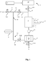
- FIG. 1 a first embodiment of a device according to the invention for the deionization of a fluid with ions dissolved therein is shown with reference to a flow chart. It is assumed below that the device is used for the deionization of water. However, the device may also be used in a similar manner to remove ions from other fluids.
- the device comprises a feed device 2 for supplying a feed stream F of the water to be deionized.
- the feed stream F is expediently first supplied to a treatment device 19, in which the water is treated by softening.
- the pre-treatment device 19 is designed so that a full softening of the water can take place.
- the treatment device 19 may be, for example, a water softener with ion exchangers or a reverse osmosis system.
- sodium salts sodium chloride, sulfate, nitrate, - bicarbonate
- These salts have very high solubilities.
- the yields obtainable by the process according to the invention are determined by the corresponding solubility limits of these salts.
- the device further comprises a line circuit 14, which is connected via a supply line 9 with a valve V9 arranged therein with the supply device 2.
- a Deionisationsmodul 1 a discharge device 15, a buffer 3 and (optionally) a pump 11 are arranged.
- the prepared water coming from the supply device 2 is introduced via the supply line 9 as a feed stream F with open valve V9 in the line circuit 14 and flows there first in the buffer 3 and downstream of the buffer 3 in the Deionisationsmodul 1.
- the feed stream F of the water thereby promoted by the pump 11.
- the water is at least partially deionized by the remaining ions that still in the already treated (especially fully softened) water are removed by electrochemical means from the water.
- EDI electrodeionization
- CDI capacitive Deionisationsmodul
- MCDI membramkapazitives Deionisationsmodul
- the outlet of the deionization module 1 is connected to a discharge device 15.
- the discharge device 15 contains a first discharge line 10, which is part of the line circuit 14, and a second discharge line 16, which leads away from the line circuit 14.
- a valve V10 and a measuring device 4 are arranged in the first discharge line 10.
- a valve V16 is arranged in the second discharge line 16.
- the first discharge line 10 serves for the removal of a diluate stream P and a recycling stream R.
- the second discharge line 16 is used for the removal of a concentrate stream K.
- the measuring device 4 can also be connected via a branch line to the first discharge line 10.
- the measuring device 4 is a measuring device for detecting one or more parameters of the at least partially deionized water in the deionization module 1.
- the measuring device 4 may in particular be a measuring device for detecting the conductivity (conductance) of the water. In the following it is assumed that the measuring device 4 detects the conductivity of the water.
- the measuring device 4 other parameters of the water capture, such as the total salt concentration, the pH, the redox potential, the hardness of the water and / or the concentration of at least one dissolved in water ion.
- the first discharge line 10 of the discharge device 15 branches off at a branching point into a diluate line 5 and a recycling line 6, wherein the recycling line 6 is part of the line circuit 14 and leads away the diluate line 5 from the line circuit 14.
- a valve V5 and V6 is arranged in each case.
- the diluate line 5 serves to discharge a diluate stream P from the line circuit 14.
- the recycling line 6 serves to return a recycling stream R through the line circuit 14 to the intermediate store 3.
- the measuring device 4 is coupled to a control device (not illustrated here) of the device and transmits the detected measured value or the measured values to the control device.
- the control device controls, depending on the measured value or the measured values, the position of the valves V5, V6, V9, V10 and V16.
- the buffer 3 is used for temporarily storing only partially deionized water.
- the buffer 3 has, compared to the Deionisationsmodul 1 on a much larger recording volume.
- the uptake volume of the deionization module 1 is preferably in the range from 170 to 1500 ml.
- the uptake volume of the deionization module 1 is thus substantially smaller than the uptake volume of the buffer 3 and is preferably within the range from 0.05% to 10%, preferably in the range of 0.1% to 1.0% of the receiving volume of the buffer 3.
- a feed stream F is fed from the supply device 2 via the line 9 with the valve V9 open into the temporary store 3 until it has been filled to an upper volume level a.
- the water is introduced into the deionization module 1 during a diluate production phase and is at least partially deionized therein.
- an electrical voltage is applied to the electrodes of the deionization module 1 (for example a CDI module or a MCDI module) during the diluate production phase, the anode being positive and the cathode being negatively polarized.
- the at least partially deionized water in the deionization module 1 is conducted into the first discharge line 10 of the discharge device 15 when the valve V10 is open and the valve V16 is closed.
- the measuring device 4 detects the conductivity (conductance) of the introduced water and transmits the detected measured value to the control device.
- the control device compares the measured value (conductivity of the water) detected by the measuring device 4 with a predetermined desired value for the conductivity. When the measured values detected by the measuring device 4 are below the predetermined nominal value of the conductivity, the water is discharged as diluate flow P from the line circuit 14 with the valve V5 open and the valve V6 closed, and either a diluate tank not shown here or directly using the deionized water Diluate fed.
- the only partially deionized water is conducted via the recycling line 6 through the recycling circuit 14 to the intermediate store 3 with the valve V5 closed and the valve V6 open, and temporarily stored therein.
- the buffer 3 has a level measurement 17, which detects the volume level 7 of the water stored in the buffer 3.
- the level measurement 17 is coupled to the control device and forwards the detected volume level 7 of the water in the buffer 3 to the control device.
- the (partially deionized) water fed into the intermediate storage 3 as recycling stream R is introduced into the deionization module 1 either by the pump 11 or by gravity, if necessary several times in the circulation, where a (further) deionization of the already partially deionized Water takes place until the conductivity of the water has detected by the measuring device 4 measured value, which is below the predetermined setpoint.
- the water is considered to be completely deionized and is discharged from the discharge circuit 15 via the diluate line 5 from the line circuit 14 as diluate stream P.
- the volume of the water in the buffer 3 is lowered from the upper level a to a middle level b.
- the corresponding difference volume (Va-Vb) thus corresponds to the (pumped-out) diluate volume.
- a limit value of an average volume level b is predetermined in the control device and the delivery of the diluate flow P takes place only until the predetermined limit value of the mean volume level b has fallen below.
- the promotion is turned off.
- the line circuit 14 via the feeding device 2 again a feed stream F of processed, in particular fully softened water, fed to the buffer 3 to replenish the upper volume level a.
- the water present in it after replenishment of the buffer 3 is then circulated again in the recycling mode, if necessary several times, in the line circuit 14 and deionized in the deionization module 1 until the predetermined nominal value for the conductivity is undershot.
- the valves V10, V5, V6, V9 and V16 are closed in a concentrate production phase and the deionization module 1 is operated with reversed polarity of the electrodes in comparison to the diluate production phase.
- the ions deposited on the electrodes and / or ion exchange membranes of the deionization module 1 during the dilute production phase dissolve, for example by electro-desorption, and diffuse into the water which is in the deionization module during the concentrate production phase.
- no water is passed into the deionization module 1.
- the removal of the concentrate from the deionization module 1 is expediently carried out until the concentrate has been completely removed from the deionization module 1.
- the volume level of the water is lowered in the buffer 3, in particular from the middle level b to a lower level c.
- the level difference Vb-Vc corresponds to the Aufhahmevolumen the Deionisations owned 1 and the volume of the concentrate generated during the concentrate formation phase.
- the valve V16 is closed.
- a new diluate production phase can be initiated by opening the valve V16 and opening the valves 10 and V6 and operating the deionization module 1 again in reverse polarity of the electrodes, ie with positively polarized anode and negatively polarized cathode becomes.
- the water which has been used for discharging the concentrate from the deionization module 1 is first partially deionized in the deionization module 1 and recycled via the line circuit 14 as recycling stream R back into the buffer 3 and from there to the deionization module 1 for further deionization.
- Va is the upper volume level
- Vb is the mean volume level
- Vc is the lower volume level.
- the concentrate removal system (removal line 16) has the lowest possible volume and low pressure difference.
- the described yield control via a level regulation of the buffer 3 allows a simple and flexible adjustment of the yield of different salt concentrations (or solubility limits) of the feedwater (feed flow F) over the upper volume level Va and the mean volume level Vb (possibly also over the lower Volume level Vc).
- the (controllable) volume of the diluate production phase which results from the difference between the upper volume level Va and the mean volume level Vb, (ie Va-Vb), ultimately determines the concentration in the chambers and / or at the electrodes of the deionization module 1 (Formula ( 3)).
- Vb-Vc volume difference of volume levels b and c (middle and lower levels) Vb-Vc becomes equal to or only slightly greater than the volume of equipment (uptake volume) of deionization module 1 (eg, a CDI module or MCDI module , each with a plurality of cells) and chosen to be significantly smaller than the volume of the buffer 3.
- deionization module 1 eg, a CDI module or MCDI module , each with a plurality of cells
- the volume difference of the volume levels b and c (middle and lower level) Vb-Vc also provides at least part of the volume of the discharge line 16 in addition to the volume of the device (holding volume) of the deionization module 1.
- deposits can be avoided by highly oversaturated concentrates when the concentrate is removed immediately after the deionization module, in particular at valve V16.
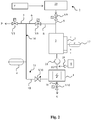
- FIG. 2 a second embodiment of a device according to the invention for the deionization of a fluid with ions dissolved therein is shown with reference to a flow chart.
- This embodiment of the invention is particularly suitable for use in dishwashers for the salt-free deionization of dishwashing water.
- the one for this used device essentially corresponds to the device of FIG. 1 and additionally contains a metering device 8 with which a conditioning agent is metered into the deionization module 1 during and / or after the concentrate production phase in order to prevent precipitations in the concentrate formed during the concentrate production phase in the deionization module 1.
- the conditioning agent acts as a complexing agent for metal ions or atoms and / or for hardness-forming ions, in particular calcium and magnesium ions and carbonate ions.
- the conditioning agent is an acidic, aqueous solution containing in particular organic acids, such as citric and / or lactic acid and / or complexing agents, in particular for the complexation of calcium and magnesium ions.
- the conditioning agent is metered during and / or after a concentrate production phase by means of the metering device 8 at a metering point 19 in the line circuit 14.
- a metering pump 18 is provided, which pumps the conditioning agent from a storage container to the metering point 19.
- the metering point 19 is preferably located upstream of the deionization module 1, as in FIG FIG. 2 shown.
- the addition of the conditioning agent in the Deionisationsmodul 1 prevents metal ions and hardness-forming ions precipitate as salts and accumulate in Deionisationsmodul 1 and this can contaminate it.
- the embodiment of FIG. 2 is particularly suitable for use in dishwashers, because here a rinse aid is metered into the dishwashing water in order to improve the drying of the dishes in the dishwasher, and this from time to time a rinse aid, eg. As an aqueous solution, in a reservoir of Dishwasher is added.
- a rinse aid eg. As an aqueous solution, in a reservoir of Dishwasher is added.
- the deionization module 1 is preferably designed as an MCDI module.
- a conditioning agent for example a rinse aid
- the metered volume of the conditioning agent must be taken into account in the buffer 3 in the level control 7.
- a conditioning agent for example a rinse aid
- the device according to the invention and the method according to the invention can also be used for other applications, such as e.g. for the deionization of swimming pool water.
Landscapes
- Engineering & Computer Science (AREA)
- Chemical & Material Sciences (AREA)
- Water Supply & Treatment (AREA)
- Chemical Kinetics & Catalysis (AREA)
- Health & Medical Sciences (AREA)
- Life Sciences & Earth Sciences (AREA)
- Urology & Nephrology (AREA)
- Analytical Chemistry (AREA)
- Hydrology & Water Resources (AREA)
- General Chemical & Material Sciences (AREA)
- Environmental & Geological Engineering (AREA)
- Electrochemistry (AREA)
- Organic Chemistry (AREA)
- Molecular Biology (AREA)
- Water Treatment By Electricity Or Magnetism (AREA)
Abstract
Description
- Die Erfindung betrifft eine Vorrichtung zur Deionisation eines Fluids mit darin gelösten Ionen, insbesondere zur elektrochemischen Deionisation von Wasser, nach dem Oberbegriff des Anspruchs 1. Die Erfindung betrifft ferner ein Verfahren zur Deionisation eines Fluids, insbesondere zur elektrochemischen Deionisation von Wasser, nach dem Oberbegriff des Anspruchs 7.
- Aus dem Stand der Technik sind verschiedene Verfahren zur Entsalzung bzw. Deionisation (Demineralisierung) von Flüssigkeiten, insbesondere von Wasser, bekannt, wie z.B. die Elektrodeionisation (EDI), die kapazitive Deionisation (CDI) und die membran-kapazitive Deionisation (MCDI). Bei der Elektrodeionisation handelt es sich um eine Kombination aus Ionenaustausch und Elektrodialyse, wobei das zu demineralisierende Fluid (bpsw. Wasser mit darin gelösten Ionen) einem Elektrodeionisationsmodul (EDI-Modul) zugeführt wird, um die im Fluid gelösten Stoffe (Ionen) aus dem Fluid zu entfernen. Das Fluid fließt dabei kontinuierlich in das Elektrodeionisationsmodul und darin senkrecht zu einem im Modul anliegenden elektrischen Feld durch Kammern, die jeweils von einer Anionenaustauschermembran und einer Kationenaustauschermembran begrenzt und mit einem Mischbettionenaustauscher gefüllt sind. Durch das elektrische Feld kommt es zu einer Ladungswanderung der gelösten Ionen zur jeweiligen Elektrode. Die Ionenaustauschermembranen erlauben dabei den Durchtritt von Anionen, während Kationen an der Durchdringung gehindert werden, und umgekehrt. Bei der Elektrodialyse findet schon bei der Diluatproduktion eine Konzentratbildung (Diffusion von Ionen durch Ionenaustauschermembranen) statt, wobei das während der Diluatproduktion erzeugte Konzentrat unmittelbar abgeführt oder in Konzentratkammern der Elektrodialysezelle gespeichert wird.
- Bei der kapazitiven Deionisation wird das zu deionisierende Fluid zwischen zwei Elektroden (Anode und Kathode) durchgeführt, über die eine elektrische Potentialdifferenz angelegt ist. In dem Fluid gelöste Anionen wandern aufgrund der Potentialdifferenz zur positiv gepolten Anode und im Fluid gelösten Kationen wandern zur negativ gepolten Kathode. Die Elektroden können dabei aus einem porösen Material, bspw. poröser Kohlenstoff, gebildet sein und die Ionen (Anionen bzw. Kationen) sammeln sich in der Poren der jeweiligen Elektroden an. Bei der membran-kapazitiven Deionisation sind an den Elektroden Ionenaustauschermembrane angeordnet. An der Kathode ist dabei eine Kationenaustauschermembran und an der Anode ist eine Anionenaustauschermembran angeordnet.
- Bei der kapazitiven bzw. der membrankapazitiven Deionisation sammeln sich die Ionen während einer Diluatproduktionsphase, in der die Anode positiv gepolt und die Kathode negativ gepolt ist, an den Ionenaustauschermembranen bzw. den Elektroden an, wodurch die Ionen aus dem Fluid entfernt werden. Das von den Ionen befreite Fluid wird als Diluat abgeführt. Zur Regenerierung der Elektroden bzw. der Ionenaustauschermembrane wird die Polung der Elektroden während einer Regenerierungs- bzw. Konzentratproduktionsphase umgekehrt, wodurch sich die an den Elektroden bzw. den Ionenaustauschermembranen haftenden Ionen ablösen und in dem während der Konzentratproduktionsphase durch das Modul strömende Fluid gelöst werden. Dadurch wird während der Konzentratproduktionsphase ein Konzentrat des Fluids mit einer hohen Konzentration darin gelöster Ionen erzeugt, während die Elektroden bzw. die Ionenaustauschermembranen für nachfolgende Diluatproduktionsphasen regeneriert werden.
- Das in den Elektrodeionisations- bzw. kapazitiven Deionisations-Verfahren während der Konzentratproduktionsphase erzeugte Konzentrat des Fluids mit einer hohen Konzentration der darin gelösten Ionen wird als Ausschuss abgeführt. Das in dem als Ausschuss abgeführten Konzentrat enthaltene Fluid kann nicht zur Erzeugung eines Diluats verwendet werden und verringert deshalb die Ausbeute des Deionisationsverfahrens.
- Zur Verbesserung der Ausbeute eines kapazitiven Deionisationsverfahrens schlägt die
EP 2 739 573 B1 eine Vorrichtung zur Rückgewinnung von deionisiertem Wasser aus einem Speisewasserstrom vor, in der der Speisewasserstrom in eine kapazitive Deionisierungszelle geleitet und darin bei Anlegung einer elektrischen Spannung an die Deionisierungszelle während einer Diluatproduktionsphase deionisiert wird, wobei während der Diluatproduktionsphase die Salzkonzentration des aus der Deionisierungszelle austretenden Wassers gemessen wird und über ein Mehrwegeventil, in Abhängigkeit der gemessenen Salzkonzentration, ein Recycling durch eine Rückführung des nur teilweise deionisierten Wassers in die Deionisierungszelle erfolgt, wenn die gemessene Salzkonzentration zwischen einem festgelegten unteren und einem oberen Sollwert liegt. Wenn die gemessene Salzkonzentration unter dem festgelegten unteren Sollwert liegt, wird das aus der Deionisierungszelle austretende Wasser als Diluatstrom (vollständig deionisiertes Wasser) abgeführt und wenn die gemessene Salzkonzentration über dem festgelegten oberen Sollwert liegt, wird das aus der Deionisierungszelle austretende Wasser zurückgewiesen und als Abwasser abgeführt. - Mit dieser Vorrichtung kann die Ausbeute der Deionisation, also der Anteil des zugeführten Speisewasserstroms, der (gemäß der Vorgabe des unteren Sollwerts der Salzkonzentration) vollständig deionisiert werden konnte, erhöht werden. Allerdings wird auch bei dieser Vorrichtung während einer Konzentratproduktionsphase, in der die kapazitive Deionisierungszelle regeneriert wird, eine erhebliche Menge von Konzentrat erzeugt, das als Ausschuss verworfen werden muss und nicht als Diluat zur Verfügung steht, weil während der Konzentratproduktionsphase Wasser in die Deionisierungszelle geleitet und dort zum Konzentrat aufgesalzt wird.
- Hiervon ausgehend liegt der Erfindung die Aufgabe zugrunde, die Ausbeute in einer Vorrichtung und einem Verfahren zur Deionisation eines Fluids mit darin gelösten Ionen weiter zu verbessern.
- Diese Aufgabe wird mit einer Vorrichtung mit den Merkmalen des Anspruchs 1 und einem Verfahren mit den Merkmalen des Anspruchs 7 gelöst. Bevorzugte Ausführungsformen der Vorrichtung und des Verfahrens sind in den abhängigen Ansprüchen aufgezeigt.
- Die erfindungsgemäße Vorrichtung umfasst wenigstens ein Deionisationsmodul, welches zur Deionisation eines Fluids mit darin gelösten Ionen in einer Diluatproduktionsphase und zur Regenerierung in einer Konzentratproduktionsphase betreibbar ist, sowie eine Zufuhreinrichtung zum Einleiten eines Feedstroms des Fluids in das Deionisationsmodul und eine Abfuhreinrichtung zum Abführen des zumindest teilweise deionisierten Fluids aus dem Deionisationsmodul als Diluatstrom oder als Recyclingstrom. Die Vorrichtung umfasst weiterhin eine Steuereinrichtung, welche so eingerichtet ist, dass sie das deionisierte Fluid aus dem Deionisationsmodul als Diluatstrom in der Diluatproduktionsphase abführt, wenn das deionisierte Fluid einen vorgegebenen Qualitätswert erfüllt, oder andernfalls das nur teilweise deionisierte Fluid aus dem Deionisationsmodul als Recyclingstrom zurück in das Deionisationsmodul leitet, so dass das nur teilweise deionisierte Fluid in dem Deionisationsmodul weiter deionisiert werden kann. Gemäß der Erfindung umfasst die Vorrichtung weiterhin einen mit dem Deionisationsmodul in Verbindung stehenden Zwischenspeicher, in den der Recyclingstrom geleitet und zwischengespeichert wird, wobei die Steuereinrichtung der erfindungsgemäßen Vorrichtung so eingerichtet ist, dass sie das Deionisationsmodul zur Regenerierung in der Konzentratproduktionsphase zumindest im Wesentlichen ohne Einleitung von Fluid in das Deionisationsmodul betreibt.
- In der erfindungsgemäßen Vorrichtung und dem erfindungsgemäßen Verfahren erfolgt während der Konzentratproduktionsphase, in der das Deionisationsmodul regeneriert wird, zumindest im Wesentlichen keine Anströmung des Deionisationsmoduls durch das Fluid. Während der Konzentratproduktionsphase befindet sich deshalb zumindest im Wesentlichen nur das Volumen des Fluids in dem Deionisationsmodul, das bereits zu Beginn der Konzentratproduktionsphase in dem Deionisationsmodul enthalten war. Dieses Volumen des Fluids wird während der Konzentratproduktionsphase aufgesalzt, indem die an den Elektroden bzw. Membranen des Desionisationsmoduls angelagerten Ionen durch Anlegen einer elektrischen Spannung mit entgegengesetzter Polarität, verglichen mit der Polung der Elektroden während der Diluatproduktionsphase, abgelöst werden und sich in dem Volumen des Fluids, das sich während der Konzentratproduktionsphase im Deionisationsmodul befindet, lösen. Dadurch wird während der Konzentratproduktionsphase in dem Deionisationsmodul ein hochkonzentriertes Konzentrat erzeugt, welches nach Beendigung der Konzentrationsproduktionsphase als Ausschuss (Abwasser) abgeführt und beispielsweise in einen Abflusskanal geleitet werden kann.
- Das Volumen des während der Konzentratproduktionsphase gebildeten Konzentrats entspricht dabei zumindest im Wesentlichen nur dem Volumen des Fluids, das sich bereits zu Beginn der Konzentratproduktionsphase im Deionisationsmodul befunden hat. Während der Konzentratproduktionsphase wird zumindest im Wesentlichen kein weiteres Fluid in das Deionisationsmodul eingeleitet. Aufgrund des geringen Volumens des während der Konzentratproduktionsphase in dem Deionisationsmodul gebildeten Konzentrats wird die Ausbeute des vollständig bzw. weitgehend deionisierten Fluids deutlich erhöht.
- Zur Erhöhung der Ausbeute trägt dabei bei, dass der Zwischenspeicher im Vergleich zu dem Deionisationsmodul ein wesentlich größeres Aufnahmevolumen aufweist. Bevorzugt ist das Aufhahmevolumen des Zwischenspeichers um einen Faktor zwischen 10 und 2000 größer als das Aufnahmevolumen des Deionisationsmoduls. Besonders bevorzugt liegt das Verhältnis der Aufhahmevolumen des Zwischenspeichers und des Deionisationsmoduls zwischen 100 und 1000.
Das in dem Zwischenspeicher gespeicherte Fluid, welches als teilweise deionisierter Recyclingstrom während der Diluatproduktionsphase in den Zwischenspeicher geleitet und dort zwischengespeichert worden ist, kann nach Beendigung der Konzentratproduktionsphase verwendet werden, um das sich im Deionisationsmodul befindliche Konzentrat durch Verdrängung aus dem Deionisationsmodul als Konzentratstrom abzuleiten. Hierfür kann das sich im Zwischenspeicher befindliche Fluid nach Beendigung der Konzentratproduktionsphase beispielsweise durch eine Pumpe oder schwerkraftbedingt in das Deionisationsmodul eingeleitet werden, um das sich darin befindliche Konzentrat zu verdrängen und auszuleiten. - Zum Abführen des Konzentrats aus dem Deionisationsmodul nach Beendigung der Konzentratproduktionsphase ist es zur Aufrechterhaltung einer möglichst hohen Ausbeute vorteilhaft, wenn das sich im Zwischenspeicher befindliche Fluid nach der Konzentrationsproduktionsphase stufenweise in das Deionisationsmodul eingeleitet wird, um das sich darin befindliche Konzentrat durch Verdrängung abzuführen. Zweckmäßig wird hierfür nach Beendigung der Konzentratproduktionsphase ein Volumen des sich im Zwischenspeicher befindlichen Fluids in das Deionisationsmodul geleitet, welches dem Aufhahmevolumen (Kapazität) des Deionisationsmoduls entspricht. Das zum Abführen des Konzentrats aus dem Deionisationsmodul verwendete Volumen des Fluids wird zweckmäßig in der der Konzentratproduktionsphase nachfolgenden Diluatproduktionsphase wieder als Recyclingstrom in den Zwischenspeicher und von dort in das Deionisationsmodul geleitet, so dass dieses Volumen des Fluids in der nachfolgenden Diluatproduktionsphase in dem Deionisationsmodul deionisiert und als Diluatstrom aus dem Deionisationsmodul abgeführt werden kann.
- In dem erfindungsgemäßen Verfahren kann das Fluid in dem Deionisationsmodul mittels elektrolytischer, elektrodialytischer, kapazitiver oder membrankapazitiver Verfahren während der Diluatproduktionsphase deionisiert werden, indem die im Fluid gelösten Ionen aus dem Fluid bspw. durch Adsorption an Elektroden oder Ionenaustauschermembranen des Deionisationsmoduls, entfernt werden. In der erfindungsgemäßen Vorrichtung ist entsprechend ein Deionisationsmodul vorgesehen, in dem ein elektrolytisches, elektrodialytisches, kapazitives oder membrankapazitives Deionisationsverfahren durchführbar ist. Das Deionisationsmodul kann bspw. ein Elektrodeionisationsmodul (EDI), ein kapazitives Deionisationsmodul (CDI) oder ein membrankapazitives Deionisationsmodul (MCDI) sein und wenigstens eine Deionisationszelle enthalten. Bevorzugt sind zur Erhöhung der Diluatmenge, die pro Zeiteinheit erzeugt werden kann, mehrere Deionisationszellen in dem Deionisationsmodul enthalten, die parallel betrieben werden.
- Gemäß der Erfindung erfolgt dabei eine Förderung des Fluids in einem Kreislauf (Recycle-Betrieb), d.h. in der Diluatproduktionsphase wird das deionisierte Fluid aus dem Deionisationsmodul als Diluatstrom abgeführt, wenn das deionisierte Fluid einen vorgegebenen Qualitätswert erfüllt, und ansonsten im Kreislaufbetrieb wieder als Recyclingstrom zurück in das Deionisationsmodul geleitet. Bei dem vorgegebenen Qualitätswert kann es sich bspw. um einen Sollwert für die Leitfähigkeit (Leitwert) und/oder die Gesamt-Salzkonzentration und/oder die Härte des Fluids (ausgedrückt durch dH oder den Gehalt an härtebildenden Ionen, insbeondere Calcium- und Magnesium-Ionen) und/oder die Konzentration wenigstens eines im Fluid gelösten Ions (und dabei insbesondere der härtebildenden Ionen, wie Calcium- und Magnesium-Ionen) handeln. Wenn der vorgegebene Qualitätswert nicht erreicht wird, also bspw. ein als Obergrenze definierter Sollwert für die Salzkonzentration oder die Leitfähigkeit überschritten ist, wird das nur teilweise deionisierte Fluid aus dem Deionisationsmodul als Recyclingstrom abgeführt, in den Zwischenspeicher geleitet und von dort zurück in das Deionisationsmodul geführt, um den Restgehalt der im Fluid gelösten Ionen zu entfernen und das Fluid vollständig zu deionisieren. Eine zu erzielende vollständige Deionisation wird dabei durch den vorgegebenen Qualitätswert definiert.
- Zur Erfassung des Qualitätswerts enthält die erfindungsgemäße Vorrichtung zweckmäßig eine Messeinrichtung, bspw. einen Leitfähigkeitssensor, eine Einrichtung zur Erfassung des pH-Werts und/oder des Redoxpotentials und/oder der Härte des Fluids oder einen Sensor zur Erfassung der gesamten Salzkonzentration oder der Konzentration wenigstens eines im Fluid gelösten Ions. Der von der Messeinrichtung erfasste Messwert wird in der Steuereinrichtung mit dem vorgegebenen Qualitätswert verglichen, um fest zu stellen, ob der Qualitätswert erfüllt ist und um zu steuern, ob das Fluid als Diluatstrom oder als Recyclingstrom aus dem Deionisationsmodul abgeführt wird.
- Während der Diluatproduktionsphase erfolgt die Abführung des Diluatstroms bevorzugt nur solange, wie der vorgegebene Qualitätswert eingehalten wird und bis ein vorgegebenes mittleres Volumenniveau im Zwischenspeicher unterschritten wird. Der Diluatstrom kann dabei einem Diluattank zugeführt und darin für eine spätere Verwendung gespeichert oder direkt einer Verwendung des Diluats zugeführt werden. Der Diluatstrom wird während der Diluatproduktionsphase bevorzugt im Batchbetrieb aus dem Deionisationsmodul abgeführt und in einem Diluattank gespeichert oder direkt einer Verwendung des Diluats zugeführt.
- Eine effiziente Abführung des während der Konzentratproduktionsphase in dem Deionisationsmodul aufgesalzten Fluids als Konzentratstrom kann erreicht werden, wenn während oder nach der Konzentratproduktionsphase Fluid aus dem Zwischenspeicher, bevorzugt stufenweise, in das Deionisationsmodul geleitet wird. Dadurch wird das während der Konzentratproduktionsphase in dem Deionisationsmodul aufgesalzte Konzentrat verdrängt und dadurch aus dem Deionisationsmodul abgeführt. Zweckmäßig und energiesparend erfolgt dabei die Einleitung des Fluids in das Deionisationsmodul schwerkraftbedingt, indem der Zwischenspeicher oberhalb des Deionisationsmoduls angeordnet wird. Alternativ oder unterstützend kann das Fluid auch mittels einer Pumpe vom Zwischenspeicher in das Deionisationsmodul gefördert werden.
- Beim Einsatz einer oder mehrerer Elektrodialysezelle(n) als Deionisationsmodul in dem erfindungsgemäßen Verfahren findet schon bei der Diluatproduktion auch eine Konzentratbildung (Diffusion von Ionen durch Ionenaustauschermembranen) statt. In dem erfindungsgemäßen Verfahren wird das während der Diluatproduktionsphase gebildete Konzentrat zunächst in Konzentratkammern des Deionisationsmoduls zwischengespeichert und erst bei der Regenerierung abgeführt. Unter Konzentratproduktionsphase wird dabei die Phase verstanden, in der zur Regenerierung der Elektrodialysezelle(n) das zwischengespeicherte Konzentrat als Konzentratstrom abgeführt wird.
- Beim Einsatz eines kapazitiven Deionisationsmoduls (CDI) oder eines membrankapazitiven Deionisationsmoduls (MCDI) finden in der Diluatproduktionsphase des erfindungsgemäßen Verfahrens Adsorptionsvorgänge an den Elektroden statt und die Überführung der Ionen zurück ins Fluid unter Konzentratbildung findet erst bei der Regenerierung während der Konzentratproduktionsphase statt.
- Der nach Beendigung der Konzentratproduktionsphase abgeführte Konzentratstrom kann als Ausschuss (Abwasser) in einen Ausguss geleitet oder einer Konditionierung zugeführt werden. Die Abführung des Konzentratstroms aus dem Deionisationsmodul erfolgt dabei zweckmäßig durch Verdrängung von Fluid aus dem Zwischenspeicher und so lange, bis ein vorgegebenes unteres Volumenniveau im Zwischenspeicher unterschritten wird. Dadurch kann die Ausbeute optimiert werden und es wird sichergestellt, dass nur möglichst wenig Fluid aus dem Zwischenspeicher, das bereits teilweise deionisiert worden ist, als Ausschuss verworfen wird und nicht mehr zur Erzeugung von Diluat genutzt werden kann. Nach Abführung des Konzentrats aus dem Deionisationsmodul kann wieder eine neue Diluatproduktionsphase begonnen werden, in der das Niveau des (bereits teilweise deionisierten) Fluids in dem Zwischenspeicher wieder bis zu einem oberen Volumenniveau aufgefüllt wird.
- Um Ausfällungen in dem Konzentrat, das während der Konzentratproduktionsphase im Deionisationsmodul gebildet worden ist, zu verhindern, wird bevorzugt während und/oder nach der Konzentratproduktionsphase ein Konditionierungsmittel in das Deionisationsmodul dosiert. Das Konditionierungsmittel wirkt dabei als Komplexbildner für Metallionen oder - atome und/oder für härtebildende Ionen, insbesondere Calcium- und Magnesiumionen. Durch das Konditionierungsmittel werden die Metallionen oder -atome und/oder die härtebildenden Ionen komplexiert und es wird dadurch verhindert, dass die härtebildenden Ionen als Kalk ausfällen bzw. dass die metallischen Ionen oder Atome sich im Deionisationsmodul anlagern und dieses dadurch verunreinigen können, bspw. durch Kalkablagerungen oder durch Korrossion.
- Bevorzugt handelt es sich bei dem Konditionierungsmittel um eine saure, wässrige Lösung, die insbesondere organische Säuren, wie z.B. Zitronen- und/oder Milchsäure, und/oder Komplexbildner, insbesondere zur Komplexbildung von Calcium- und Magnesiumionen, enthält. Derartige Konditionierungsmittel stehen bspw. als Klarspüler für Geschirrspülmaschinen zur Verfügung und sind kostengünstig erhältlich.
- Diese und weitere Merkmale sowie Vorteile der erfindungsgemäßen Vorrichtung und des erfindungsgemäßen Verfahrens gehen aus den nachfolgend unter Bezugnahme auf die begleitenden Zeichnungen näher beschriebenen Ausführungsbeispielen hervor. Die Zeichnungen zeigen:
- Figur 1:
- Schematische Darstellung eines ersten Ausführungsbeispiels einer erfindungsgemäßen Vorrichtung anhand eines Fließschemas;
- Figur 2:
- Schematische Darstellung eines zweiten Ausführungsbeispiels einer erfindungsgemäßen Vorrichtung anhand eines Fließschemas;
- In
Figur 1 ist ein erstes Ausführungsbeispiel einer erfindungsgemäßen Vorrichtung zur Deionisation eines Fluids mit darin gelösten Ionen anhand eines Fließschemas gezeigt. Es wird im Folgenden davon ausgegangen, dass die Vorrichtung zur Deionisation von Wasser eingesetzt wird. Die Vorrichtung kann jedoch in entsprechender Weise auch zur Entfernung von Ionen aus anderen Fluiden verwendet werden. - Die Vorrichtung umfasst eine Zufuhreinrichtung 2 zur Zuführung eines Feedstroms F des zu deionisierenden Wassers. Der Feedstrom F wird dabei zweckmäßig zunächst einer Aufbereitungseinrichtung 19 zugeführt, in der das Wasser durch Enthärtung aufbereitet wird. Bevorzugt ist die Voraufbereitungseinrichtung 19 so ausgebildet, dass eine Vollenthärtung des Wassers erfolgen kann. Bei der Aufbereitungseinrichtung 19 kann es sich beispielsweise um eine Enthärtungsanlage mit Ionenaustauschern oder um eine Umkehrosmoseanlage handeln.
- Durch die Voraufbereitung (insb. eine vollständige oder teilweise Enthärtung) des Feedstroms in der Aufbereitungseinrichtung 19 liegen Natriumsalze (Natriumchlorid, -sulfat, -nitrat, - hydrogenkarbonat) im Feedstrom vor. Diese Salze weisen sehr hohe Löslichkeiten auf. Die mit dem erfindungsgemäßen Verfahren erzielbaren Ausbeuten werden dabei durch die entsprechenden Löslichkeitsgrenzen dieser Salze bestimmt.
- Die Vorrichtung umfasst weiterhin einen Leitungskreislauf 14, der über eine Zufuhrleitung 9 mit einem darin angeordneten Ventil V9 mit der Zufuhreinrichtung 2 verbunden ist. In dem Leitungskreislauf 14 sind ein Deionisationsmodul 1, eine Abfuhreinrichtung 15, ein Zwischenspeicher 3 und (optional) eine Pumpe 11 angeordnet.
- Das von der Zufuhreinrichtung 2 kommende, aufbereitete Wasser wird über die Zufuhrleitung 9 als Feedstrom F bei geöffnetem Ventil V9 in den Leitungskreislauf 14 eingeleitet und strömt dort zunächst in den Zwischenspeicher 3 und stromabwärts des Zwischenspeichers 3 in das Deionisationsmodul 1. Der Feedstrom F des Wassers wird dabei von der Pumpe 11 gefördert.
- In dem Deionisationsmodul 1, bei dem es sich beispielsweise um ein Elektrodeionisationsmodul (EDI), ein kapazitives Deionisationsmodul (CDI) oder um ein membramkapazitives Deionisationsmodul (MCDI) handeln kann, wird das Wasser zumindest teilweise deionisiert, indem die restlichen Ionen, die noch in dem bereits aufbereiteten (insbesondere vollenthärteten) Wasser enthalten sind, auf elektrochemischem Wege aus dem Wasser entfernt werden. Hierfür werden beispielsweise die Elektroden eines CDI- bzw. eines MCDI-Moduls während einer Diluatproduktionsphase mit einer elektrischen Spannung beaufschlagt, wobei die Anode positiv und die Kathode negativ gepolt wird.
- Zur Abführung des in dem Deionisationsmodul 1 zumindest teilweise deionisierten Fluids ist der Ausgang des Deionisationsmodul 1 mit einer Abfuhreinrichtung 15 verbunden. Die Abfuhreinrichtung 15 enthält dabei eine erste Abfuhrleitung 10, welche Bestandteil des Leitungskreislaufs 14 ist, sowie eine zweite Abfuhrleitung 16, die von dem Leitungskreislauf 14 wegführt. In der ersten Abfuhrleitung 10 sind ein Ventil V10 sowie eine Messeinrichtung 4 angeordnet. In der zweiten Abfuhrleitung 16 ist ein Ventil V16 angeordnet. Die erste Abfuhrleitung 10 dient der Abfuhr eines Diluatstroms P und eines Recyclingstroms R. Die zweite Abfuhrleitung 16 dient der Abfuhr eines Konzentratstroms K.
- Die Messeinrichtung 4 kann auch über eine Abzweigungsleitung mit der ersten Abfuhrleitung 10 verbunden sein. Bei der Messeinrichtung 4 handelt es sich um ein Messgerät zur Erfassung eines oder mehrerer Parameter des in dem Deionisationsmodul 1 zumindest teilweise deionisierten Wassers. Bei der Messeinrichtung 4 kann es sich insbesondere um ein Messgerät zur Erfassung der Leitfähigkeit (Leitwert) des Wassers handeln. Im Folgenden wird davon ausgegangen, dass die Messeinrichtung 4 die Leitfähigkeit des Wassers erfasst. Alternativ oder ergänzend kann die Messeinrichtung 4 auch andere Parameter des Wassers erfassen, wie z.B. die gesamte Salzkonzentration, den pH-Wert, das Redoxpotential, die Härte des Wassers und/oder die Konzentration wenigstens eines im Wasser gelösten Ions.
- Die erste Abfuhrleitung 10 der Abfuhreinrichtung 15 verzweigt sich an einer Verzweigungsstelle in eine Diluatleitung 5 und eine Recyclingleitung 6, wobei die Recyclingleitung 6 Bestandteil des Leitungskreislaufs 14 ist und die Diluatleitung 5 von dem Leitungskreislauf 14 wegführt. Sowohl in der Diluatleitung 5 als auch in der Recyclingleitung 6 ist jeweils ein Ventil V5 bzw. V6 angeordnet. Die Diluatleitung 5 dient zur Abführung eines Diluatstroms P aus dem Leitungskreislauf 14. Die Recyclingleitung 6 dient zur Rückführung eines Recyclingstroms R durch den Leitungskreislauf 14 in den Zwischenspeicher 3.
- Die Messeinrichtung 4 ist mit einer hier nicht dargestellten Steuereinrichtung der Vorrichtung gekoppelt und übermittelt den erfassten Messwert bzw. die erfassten Messwerte an die Steuereinrichtung. Die Steuereinrichtung steuert, in Abhängigkeit des Messwerts bzw. der Messwerte, die Stellung der Ventile V5, V6, V9, V10 und V16.
- Der Zwischenspeicher 3 dient zum Zwischenspeichern von nur teilweise deionisiertem Wasser. Der Zwischenspeicher 3 weist im Vergleich zu dem Deionisationsmodul 1 ein wesentlich größeres Aufnahmevolumen auf. Das Aufnahmevolumen des Zwischenspeichers 3 liegt bevorzugt im Bereich von 20 bis 300 1. Das Aufhahmevolumen des Deionisationsmoduls 1 liegt bevorzugt im Bereich von 170 bis 1500 ml. Das Aufnahmevolumen des Deionisationsmoduls 1 ist damit wesentlich kleiner als das Aufnahmevolumen des Zwischenspeichers 3 und liegt bevorzugt im Bereich von 0,05 % bis 10 %, bevorzugt im Bereich von 0,1% bis 1,0 % des Aufnahmevolumens des Zwischenspeichers 3.
- Zur Erzeugung von deionisiertem Wasser wird ein Feedstrom F von der Zufuhreinrichtung 2 über die Leitung 9 bei geöffnetem Ventil V9 in den Zwischenspeicher 3 geleitet, bis dieser zu einem oberen Volumenniveau a aufgefüllt ist. Von dort wird das Wasser während einer Diluatproduktionsphase in das Deionisationsmodul 1 eingeleitet und darin zumindest teilweise deionisiert. Dabei liegt an den Elektroden des Deionisationsmoduls 1 (bspw. eines CDI- bzw. eines MCDI-Moduls) während der Diluatproduktionsphase eine elektrische Spannung an, wobei die Anode positiv und die Kathode negativ gepolt ist.
- Das in dem Deionisationsmoduls 1 zumindest teilweise deioniserte Wasser wird bei geöffnetem Ventil V10 und geschlossenem Ventil V16 in die erste Abfuhrleitung 10 der Abfuhreinrichtung 15 geleitet. Die Messeinrichtung 4 erfasst die Leitfähigkeit (Leitwert) des eingeleiteten Wassers und übermittelt den erfassten Messwert an die Steuereinrichtung. Die Steuereinrichtung vergleicht den von der Messeinrichtung 4 erfassten Messwert (Leitwert des Wassers) mit einem vorgegebenen Sollwert für die Leitfähigkeit. Wenn der von der Messeinrichtung 4 erfasste Messwerte unterhalb des vorgegebenen Sollwerts der Leitfähigkeit liegt, wird das Wasser bei geöffnetem Ventil V5 und geschlossenem Ventil V6 als Diluatstrom P aus dem Leitungskreislauf 14 ausgeleitet und entweder einem hier nicht dargestellten Diluattank oder unmittelbar einer Verwendung des deionisierten Wassers als Diluat zugeführt.
- Wenn der von der Messeinrichtung 4 erfasste Messwert dagegen oberhalb des vorgegebenen Sollwerts für die Leitfähigkeit liegt, wird das nur teilweise deionisierte Wasser bei geschlossenem Ventil V5 und geöffnetem Ventil V6 über die Recyclingleitung 6 durch den Leitungskreislauf 14 zum Zwischenspeicher 3 geleitet und darin zwischengespeichert. Der Zwischenspeicher 3 weist eine Niveaumessung 17 auf, welche das Volumenniveau 7 des im Zwischenspeicher 3 gespeicherten Wassers erfasst. Die Niveaumessung 17 ist mit der Steuereinrichtung gekoppelt und leitet das erfasste Volumenniveau 7 des Wassers im Zwischenspeicher 3 an die Steuereinrichtung weiter.
- Das als Recyclingstrom R in den Zwischenspeicher 3 geleitete und dort zwischengespeicherte (teilweise deionisierte) Wasser wird während der Diluatproduktionsphase entweder von der Pumpe 11 oder schwerkraftbedingt, erforderlichenfalls mehrmals im Kreislauf, in das Deionisationsmodul 1 eingeleitet, wo eine (weitere) Deionisation des bereits teilweise deionisierten Wassers erfolgt, bis die Leitfähigkeit des Wassers einen von der Messeinrichtung 4 erfassten Messwert aufweist, der unterhalb des vorgegebenen Sollwerts liegt. Sobald die Leitfähigkeit des Wassers unterhalb des vorgegebenen Sollwerts liegt, gilt das Wasser als vollständig deionisiert und wird von der Abfuhreinrichtung 15 über die Diluatleitung 5 aus dem Leitungskreislauf 14 als Diluatstrom P ausgeleitet. Dadurch wird das Volumen des sich im Zwischenspeicher 3 befindlichen Wassers von dem oberen Niveau a auf ein mittleres Niveau b abgesenkt. Das entsprechende Differenzvolumen (Va - Vb) entspricht somit dem (abgepumpten) Diluatvolumen.
- Bevorzugt ist in der Steuereinrichtung ein Grenzwert eines mittleren Volumenniveaus b vorgegeben und die Förderung des Diluatstroms P erfolgt nur so lange, bis der vorgegebene Grenzwert des mittleren Volumenniveaus b unterschritten ist. Wenn der Grenzwert des mittleren Niveaus b erreicht ist, wird die Förderung abgeschaltet. Danach wird dem Leitungskreislauf 14 über die Zufuhreinrichtung 2 wieder ein Feedstrom F von aufbereitetem, insbesondere voll enthärtetem Wasser, zugeführt, um den Zwischenspeicher 3 wieder auf das obere Volumenniveau a aufzufüllen. Das sich nach Auffüllung des Zwischenspeichers 3 darin befindliche Wasser wird anschließend wieder im Recyclingbetrieb, erforderlichenfalls mehrfach, in dem Leitungskreislauf 14 zirkuliert und in dem Deionisationsmodul 1 so lange deionisiert, bis der vorgegebene Sollwert für die Leitfähigkeit unterschritten wird.
- Zur Regenerierung des Deionisationsmoduls 1 werden in einer Konzentratproduktionsphase die Ventile V10, V5, V6, V9 und V16 geschlossen und das Deionisationsmodul 1 wird, im Vergleich zur Diluatproduktionsphase, mit umgekehrter Polung der Elektroden betrieben. Dadurch lösen sich die an den Elektroden und/oder Ionenaustauschermembranen des Deionisationsmoduls 1 während der Diluatproduktionsphase angelagerten Ionen, beispielsweise durch Elektro-Desorption, und diffundieren in das Wasser, das sich während der Konzentratproduktionsphase in dem Deionisationsmodul befindet. Während der Konzentratproduktionsphase wird erfindungsgemäß kein Wasser in das Deionisationsmodul 1 geleitet. Während der Konzentratproduktionsphase befindet sich deshalb (nur) das Volumen des Wassers innerhalb des Deionisationsmoduls 1, das auch bereits zu Beginn der Konzentratproduktionsphase in dem Deionisationsmodul 1 enthalten war. Dadurch bedingt wird während der Konzentratproduktionsphase nur das geringe Volumen des Wassers zu einem Konzentrat aufgesalzt, das sich bereits zu Beginn der Konzentratproduktionsphase im Deionisationsmodul 1 befunden hat.
- Nach Beendigung der Konzentratproduktionsphase, d.h. nach vollständiger Entfernung der während der Diluatproduktionsphase in dem Deionisationsmodul 1 an den Elektroden bzw. den Ionenaustauschermembranen angelagerten Ionen, wird das während der Konzentratproduktionsphase in dem Deionisationsmodul 1 erzeugte Konzentrat durch die Abfuhrleitung 16 bei geöffnetem Ventil V16 als Konzentratstrom K aus dem Deionisationsmodul 1 abgeführt. Dies erfolgt durch Einleitung von Wasser aus dem Zwischenspeicher 3 in das Deionisationsmodul 1. Durch die schwerkraftbedingte oder durch die Pumpe 11 geförderte Einleitung des Wassers in das Deionisationsmodul 1 wird das sich darin befindliche und während der Konzentratproduktionsphase erzeugte Konzentrat verdrängt und durch die Abfuhrleitung 16 abgeführt.
- Die Abführung des Konzentrats aus dem Deionisationsmodul 1 erfolgt dabei zweckmäßig so lange, bis das Konzentrat vollständig aus dem Deionisationsmodul 1 abgeführt worden ist. Hierfür wird das Volumenniveau des Wassers in dem Zwischenspeicher 3 abgesenkt, insbesondere von dem mittleren Niveau b auf ein unteres Niveau c. Der Niveauunterschied Vb - Vc entspricht dabei dem Aufhahmevolumen der Deionisationseinrichtung 1 bzw. dem Volumen des während der Konzentratbildungsphase erzeugten Konzentrats. Sobald das untere Niveau c erreicht ist, wird das Ventil V16 geschlossen.
- Nach Abfuhr des Konzentratstroms K aus dem Deionisationsmodul 1 kann eine neue Diluatproduktionsphase eingeleitet werden, indem das Ventil V16 geschlossen und die Ventile 10 und V6 geöffnet und das Deionisationsmodul 1 wieder in umgekehrter Polung der Elektroden, also mit positiv gepolter Anode und negativ gepolter Kathode, betrieben wird. Dabei wird das Wasser, das zum Ausleiten des Konzentrats aus dem Deionisationsmodul 1 verwendet worden ist, zunächst im Deionisationsmodul 1 teilweise deionisiert und über den Leitungskreislauf 14 als Recyclingstrom R wieder zurück in den Zwischenspeicher 3 und von dort zur weiteren Deionisierung in das Deionisationsmodul 1 geleitet.
- Erfolgt nach einer Diluatproduktionsphase (in der eine Deionisation bzw. Entsalzung des Wassers erfolgt mit einem erzeugten Diluatvolumen von VDiluat erfolgt) unmittelbar eine Konzentratproduktionsphase (in der eine Konzentraterzeugung mit einem Konzentratvolumen VKonzentrat durch Aufsalzung des im Deionisationsmodul befindlichen Wassers und dadurch eine Regenerierung des Deionisationsmodul erfolgt), so beträgt die Ausbeute A


- Das Konzentratabfuhrsystem (Abfuhrleitung 16) weist ein möglichst geringes Volumen und geringe Druckdifferenz auf.
- Die beschriebene Ausbeutesteuerung über eine Niveau-Regulierung des Zwischenspeichers 3 ermöglicht eine einfache und flexible Anpassung der Ausbeute an verschiedene Salzkonzentrationen (bzw. Löslichkeitsgrenzen) des Speisewassers (Feedstrom F) über das obere Volumenniveau Va und das mittlere Volumenniveau Vb (ggf. auch über das untere Volumenniveau Vc). Das (steuerbare) Volumen der Diluatproduktionsphase, das sich aus der Differenz des oberen Volumenniveaus Va und des mittleren Volumenniveaus Vb, (also Va-Vb) ergibt, bestimmt letztendlich die Aufkonzentrierung in den Kammern und/oder an den Elektroden des Deionisationsmoduls 1 (Formel (3)).
- Mit der erfindungsgemäßen Vorrichtung und dem erfindungsgemäßen Verfahren sind hohe Ausbeuten von mehr als 90 %, bevorzugt von mehr als 95% und besonders bevorzugt von mehr als 99 % realisierbar. Um diese hohen Ausbeuten zu erzielen, wird die Volumendifferenz der Volumenniveaus b und c (mittleres und unteres Niveau) Vb - Vc gleich groß oder nur geringfügig größer als das Gerätevolumen (Aufnahmevolumen) des Deionisationsmoduls 1 (z.B. ein CDI-Modul oder ein MCDI-Modul, jeweils mit einer Mehrzahl von Zellen) und deutlich kleiner als das Volumen des Zwischenspeichers 3 gewählt. Die Volumendifferenz der Volumenniveaus b und c (mittleres und unteres Niveau) Vb - Vc sieht dabei neben dem Gerätevolumen (Aufhahmevolumen) des Deionisationsmoduls 1 auch zumindest einen Teil des Volumens der Abfuhrleitung 16 vor. Dadurch können Ablagerungen durch hoch übersättigte Konzentrate bei Abfuhr des Konzentrats unmittelbar nach dem Deionisationsmodul, insbesondere am Ventil V16, vermieden werden.
- In
Figur 2 ist ein zweites Ausführungsbeispiel einer erfindungsgemäßen Vorrichtung zur Deionisation eines Fluids mit darin gelösten Ionen anhand eines Fließschemas gezeigt. Dieses Ausführungsbeispiel der Erfindung eignet sich besonders zur Verwendung in Geschirrspülmaschinen zur salzfreien Deionisierung von Geschirrspülwasser. Die hierfür eingesetzte Vorrichtung entspricht im Wesentlichen der Vorrichtung vonFigur 1 und enthält zusätzlich noch eine Dosiereinrichtung 8, mit der während und/oder nach der Konzentratproduktionsphase ein Konditionierungsmittel in das Deionisationsmodul 1 dosiert wird, um Ausfällungen in dem Konzentrat, das während der Konzentratproduktionsphase im Deionisationsmodul 1 gebildet worden ist, zu verhindern. Das Konditionierungsmittel wirkt dabei als Komplexbildner für Metallionen oder -atome und/oder für härtebildende Ionen, insbesondere Calcium- und Magnesiumionen sowie Carbonat-Ionen. Zweckmäßig handelt es sich bei dem Konditionierungsmittel um eine saure, wässrige Lösung, die insbesondere organische Säuren, wie z.B. Zitronen- und/oder Milchsäure und/oder Komplexbildner, insbesondere zur Komplexierung von Calcium- und Magnesiumionen, enthält. - Das Konditionierungsmittel wird während und/oder nach einer Konzentratproduktionsphase mittels der Dosiereinrichtung 8 an einer Dosierstelle 19 in den Leitungskreislauf 14 eindosiert. Hierfür ist eine Dosierpumpe 18 vorgesehen, die das Konditionierungsmittel aus einem Vorratsbehälter zur Dosierstelle 19 pumpt. Die Dosierstelle 19 befindet sich vorzugsweise stromaufwärts des Deionisationsmoduls 1, wie in
Figur 2 gezeigt. Durch die Zugabe des Konditionierungsmittels in das Deionisationsmodul 1 wird verhindert, dass Metallionen und härtebildende Ionen als Salze ausfällen und sich im Deionisationsmodul 1 anlagern und dieses dadurch verunreinigen können. - Als Konditionierungsmittel können insbesondere handelsübliche Klarspüler für Geschirrspülmaschinen eingesetzt werden. Das Ausführungsbeispiel der
Figur 2 eignet sich dabei besonders zur Verwendung in Geschirrspülmaschinen, weil hier ohnehin ein Klarspüler in das Geschirrspülwasser eindosiert wird, um die Trocknung des Geschirrs in der Geschirrspülmaschine zu verbessern, und hierfür von Zeit zu Zeit ein Klarspülmittel, bspw. als wässrige Lösung, in einen Vorratsbehälter der Geschirrspülmaschine zugegeben wird. Mit der Vorrichtung gemäß dem Ausführungsbeispiel derFigur 2 kann das Geschirrspülwasser in einer Geschirrspülmaschine sehr effizient mit hohen Ausbeuten und salzfrei deionisiert werden. Das Deionisationsmodul 1 ist dabei bevorzugt als MCDI-Modul ausgebildet. - Wenn in das Deionisationsmodul 1 ein Konditionierungsmittel (bspw. ein Klarspüler) zudosiert wird, ist das eindosierte Volumen des Konditionierungsmittels bei der Niveauregulierung 7 in dem Zwischenspeicher 3 zu berücksichtigen. So wird bspw. zum Ausleiten des Konzentrats aus dem Deionisationsmodul 1 nach einer Konzentratproduktionsphase ein etwas höheres Volumen des Wassers benötigt, das aus dem Zwischenspeicher 3 in das Deionisationsmodul 1 abgelassen wird, um das Konzentrat zu verdrängen, weil damit auch das eindosierte Volumen des Konditionierungsmittels durch Verdrängung aus dem Deionisationsmodul 1 entfernt werden muss.
- Neben der Deionisation von Geschirrspülwasser können die erfindungsgemäße Vorrichtung und das erfindungsgemäße Verfahren auch für andere Anwendungen eingesetzt werden, wie z.B. für die Deionisation von Schwimmbadwasser.
Claims (15)
- Vorrichtung zur Deionisation eines Fluids mit darin gelösten Ionen, insbesondere von Wasser, mit wenigstens einem Deionisationsmodul (1), welches zur Deionisation des Fluids in einer Diluatproduktionsphase und zur Regenerierung in einer Konzentratproduktionsphase betreibbar ist, einer Zufuhreinrichtung (2) zum Einleiten eines Feedstroms (F) des Fluids in das wenigstens eine Deionisationsmodul (1), einer Abfuhreinrichtung (15) zum Abführen des zumindest teilweise deionisierten Fluids aus dem Deionisationsmodul (1) als Diluatstrom (P) oder als Recyclingstrom (R) und einer Steuereinrichtung, welche so eingerichtet ist, dass sie das deionisierte Fluid aus dem Deionisationsmodul (1) als Diluatstrom (P) in der Diluatproduktionsphase des Deionisationsmoduls (1) abführt, wenn das deionisierte Fluid einen vorgegebenen Qualitätswert erfüllt, oder andernfalls das nur teilweise deionisierte Fluid aus dem Deionisationsmodul (1) als Recyclingstrom (R) zurück in das Deionisationsmodul (1) leitet, gekennzeichnet durch einen mit dem Deionisationsmodul (1) in Verbindung stehenden Zwischenspeicher (3), in den der Recyclingstrom (R) geleitet und zwischengespeichert wird, wobei die Steuereinrichtung so eingerichtet ist, dass sie das Deionisationsmodul (1) zur Regenerierung in der Konzentratproduktionsphase zumindest im Wesentlichen ohne Einleitung von Fluid in das Deionisationsmodul (1) betreibt.
- Vorrichtung nach Anspruch 1, gekennzeichnet durch einen Leitungskreislauf (14), der mit der Zufuhreinrichtung (2) über eine Leitung (9) zur Zuführung des Feedstroms (F) verbunden ist und in dem das Deionisationsmodul (1), die Abfuhreinrichtung (15), der Zwischenspeicher (3) und wenigstens eine Pumpe (11) angeordnet sind.
- Vorrichtung nach einem der voranstehenden Ansprüche, dadurch gekennzeichnet, dass die Abfuhreinrichtung (15) eine Messeinrichtung (4) zur Erfassung des Qualitätswerts des aus dem Deionisationsmodul abgeführten Fuids umfasst, wobei es sich bei der Messeinrichtung (4) insbesondere um ein Messgerät zur Erfassung des Leitwerts und/oder der Salzkonzentration, und/oder des pH-Werts, und/oder des Redoxpotentials und/oder der Härte des Fluids und/oder der Konzentration wenigstens eines im Fluid gelösten Ions handelt, und/oder dass die Abfuhreinrichtung (15) mit einer Diluatleitung (5) zur Abführung des Diluatstroms (P) sowie mit einer Recyclingleitung (6) zur Zuführung des Recyclingstroms (R) zum Zwischenspeicher (3) in Verbindung steht.
- Vorrichtung nach Anspruch 2 oder 3, dadurch gekennzeichnet, dass die Abfuhreinrichtung (15) mit einer Abfuhrleitung (16) zur Abführung eines Konzentratstroms (K) in Verbindung steht, wobei die Steuereinrichtung so eingerichtet ist, dass sie das während oder nach der Konzentratproduktionsphase aus dem Deionisationsmodul (1) abgeführte Fluid als Konzentratstrom (K) in die Abfuhrleitung (16) leitet.
- Vorrichtung nach einem der voranstehenden Ansprüche, wobei die Steuereinrichtung so eingerichtet ist, dass sie während oder nach der Konzentratproduktionsphase Fluid aus dem Zwischenspeicher (3) insbesondere stufenweise in das Deionisationsmodul (1) leitet, um das darin während der Konzentratproduktionsphase aufgesalzte Fluid als Konzentratstrom (K) abzuführen.
- Vorrichtung nach einem der voranstehenden Ansprüche, dadurch gekennzeichnet, dass das Deionisationsmodul (1) das Fluid elektrochemisch deionisiert und hierfür wenigstens eine Elektrodialysezelle umfasst und/oder als Elektrodeionisationsmodul (EDI), als kapazitives Deionisationsmodul (CDI) oder als membrankapazitives Deionisationsmodul (MCDI) ausgebildet ist.
- Verfahren zur Deionisation eines Fluids, insbesondere von Wasser, wobei ein Feedstrom (F) des Fluids in einer Diluatproduktionsphase in einem Deionisationsmodul (1) durch Entfernung von in dem Fluid gelösten Ionen aus dem Fluid deionisiert und das Deionisationsmodul (1) in einer Konzentratproduktionsphase durch Desorption der Ionen vom Adsorber regeneriert wird und in der Diluatproduktionsphase das deionisierte Fluid aus dem Deionisationsmodul (1) als Diluatstrom (P) abgeführt wird, wenn das deionisierte Fluid einen vorgegebenen Qualitätswert erfüllt, oder andernfalls das nur teilweise deionisierte Fluid aus dem Deionisationsmodul (1) als Recyclingstrom (R) zurück in das Deionisationsmodul (1) geleitet wird, dadurch gekennzeichnet, dass der Recyclingstrom (R) in der Diluatproduktionsphase in einen mit dem Deionisationsmodul (1) in Verbindung stehenden Zwischenspeicher (3) geleitet und darin zwischengespeichert wird und dass das Deionisationsmodul (1) in der Konzentratproduktionsphase ohne Einleitung von Fluid in das Deionisationsmodul (1) regeneriert wird.
- Verfahren nach Anspruch 7, dadurch gekennzeichnet, dass sich während der Konzentratproduktionsphase nur das zu Beginn der Konzentratproduktionsphase im Deionisationsmodul (1) befindliche Volumen des Fluids im Deionisationsmodul (1) befindet.
- Verfahren nach Anspruch 7 oder 8, dadurch gekennzeichnet, dass während der Diluatproduktionsphase der Qualitätswert, insbesondere der Leitwert und/oder die Salzkonzentration, und/oder der pH-Wert, und/oder das Redoxpotential und/oder die Härte des Fluids und/oder der Konzentration wenigstens eines im Fluid gelösten Ions, erfasst und mit einem vorgegebenen Grenzwert verglichen wird.
- Verfahren nach Anspruch 9, dadurch gekennzeichnet, dass der Diluatstrom (P) während der Diluatproduktionsphase im Batchbetrieb aus dem Deionisationsmodul (1) abgeführt und in einem Diluattank gespeichert oder direkt einer Verwendung des Diluats zugeführt wird, insbesondere wenn der als Obergrenze definierte Grenzwert unterschritten wird oder wenn der als Untergrenze definierte Grenzwert überschritten wird.
- Verfahren nach Anspruch 9, dadurch gekennzeichnet, dass während der Diluatproduktionsphase das nur teilweise deionisierte Fluid aus dem Deionisationsmodul (1) als Recyclingstrom (R) zurück in das Deionisationsmodul (1) geführt wird, wenn der als Obergrenze definierte Grenzwert überschritten wird oder wenn der als Untergrenze definierte Grenzwert unterschritten wird.
- Verfahren nach einem der Ansprüche 7 bis 11, dadurch gekennzeichnet, dass während oder nach der Konzentratproduktionsphase Fluid aus dem Zwischenspeicher (3), bevorzugt stufenweise, in das Deionisationsmodul (1) geleitet wird, um das darin während der Konzentratproduktionsphase aufgesalzte Fluid als Konzentratstrom (K) abzuführen.
- Verfahren nach einem der Ansprüche 7 bis 12, dadurch gekennzeichnet, dass während der Diluatproduktionsphase die Abführung des Diluatstroms (P) erfolgt, bis ein vorgegebenes mittleres Volumenniveau (b) im Zwischenspeicher (3) unterschritten wird und/oder dass während der Konzentratproduktionsphase die Abführung des Konzentratstroms (K) aus dem Deionisationsmodul (1) erfolgt, indem das im Zwischenspeicher (3) gespeicherte Volumen des Fluids in das Deionisationsmodul (1) eingeleitet wird, bis ein vorgegebenes unteres Volumenniveau (c) im Zwischenspeicher (3) unterschritten wird.
- Verfahren nach einem der Ansprüche 7 bis 13, dadurch gekennzeichnet, dass während und/oder nach der Konzentratproduktionsphase ein Konditionierungsmittel in das Deionisationsmodul (1) dosiert wird, um Ausfällungen in dem Konzentrat, das während der Konzentratproduktionsphase im Deionisationsmodul (1) gebildet worden ist, zu verhindern, wobei das Konditionierungsmittel als Komplexbildner für Metallionen oder -atome und/oder für härtebildende Ionen, insbesondere Calcium- und Magnesiumionen, wirkt.
- Verfahren nach Anspruch 14, dadurch gekennzeichnet, dass es sich bei dem Konditionierungsmittel um eine saure, wässrige Lösung handelt, die bevorzugt organische Säuren, insbesondere Citronen- und/oder Milchsäure, und/oder Komplexbildner, insbesondere zur Komplexbildung von Calcium- und Magnesiumionen, enthält.
Applications Claiming Priority (1)
| Application Number | Priority Date | Filing Date | Title |
|---|---|---|---|
| DE102018108339.4A DE102018108339B4 (de) | 2018-04-09 | 2018-04-09 | Vorrichtung und Verfahren zur Deionisation eines Fluids mit darin gelösten Ionen, insbesondere von Wasser |
Publications (2)
| Publication Number | Publication Date |
|---|---|
| EP3552691A1 true EP3552691A1 (de) | 2019-10-16 |
| EP3552691B1 EP3552691B1 (de) | 2020-11-25 |
Family
ID=65275931
Family Applications (1)
| Application Number | Title | Priority Date | Filing Date |
|---|---|---|---|
| EP19151873.7A Active EP3552691B1 (de) | 2018-04-09 | 2019-01-15 | Vorrichtung und verfahren zur deionisation eines fluids mit darin gelösten ionen, insbesondere von wasser |
Country Status (2)
| Country | Link |
|---|---|
| EP (1) | EP3552691B1 (de) |
| DE (1) | DE102018108339B4 (de) |
Citations (3)
| Publication number | Priority date | Publication date | Assignee | Title |
|---|---|---|---|---|
| US20120298153A1 (en) * | 2010-02-08 | 2012-11-29 | Enpar Technologies Inc. | Washing appliance with dedicated water-softener |
| DE102012212638A1 (de) * | 2012-07-18 | 2014-05-22 | Premark Feg L.L.C. | Spülmaschine sowie Verfahren zum Betreiben einer Spülmaschine |
| CN106830227A (zh) * | 2017-03-01 | 2017-06-13 | 河海大学 | 一种循环处理的膜电容去离子装置及处理方法 |
Family Cites Families (4)
| Publication number | Priority date | Publication date | Assignee | Title |
|---|---|---|---|---|
| AT395969B (de) | 1991-12-04 | 1993-04-26 | Sgp Va Energie Umwelt | Verfahren zur aufbereitung von wasser oder abwasser, insbesondere zur nitratreduzierung |
| KR101947994B1 (ko) | 2011-05-25 | 2019-02-14 | 코웨이 주식회사 | 수처리 기기 |
| AU2012292237B2 (en) | 2011-08-04 | 2015-06-18 | Unilever Plc | A device and process for improved recovery of deionised water |
| GB201617347D0 (en) | 2016-10-13 | 2016-11-30 | VWS (UK) Limited | Method and apparatus for providing ultrapure water |
-
2018
- 2018-04-09 DE DE102018108339.4A patent/DE102018108339B4/de active Active
-
2019
- 2019-01-15 EP EP19151873.7A patent/EP3552691B1/de active Active
Patent Citations (3)
| Publication number | Priority date | Publication date | Assignee | Title |
|---|---|---|---|---|
| US20120298153A1 (en) * | 2010-02-08 | 2012-11-29 | Enpar Technologies Inc. | Washing appliance with dedicated water-softener |
| DE102012212638A1 (de) * | 2012-07-18 | 2014-05-22 | Premark Feg L.L.C. | Spülmaschine sowie Verfahren zum Betreiben einer Spülmaschine |
| CN106830227A (zh) * | 2017-03-01 | 2017-06-13 | 河海大学 | 一种循环处理的膜电容去离子装置及处理方法 |
Also Published As
| Publication number | Publication date |
|---|---|
| EP3552691B1 (de) | 2020-11-25 |
| DE102018108339A1 (de) | 2019-10-10 |
| DE102018108339B4 (de) | 2022-01-20 |
Similar Documents
| Publication | Publication Date | Title |
|---|---|---|
| DE69720310T2 (de) | Vorrichtung und Verfahren zur Reinigung einer Flüssigkeit mittels Elektrodeionisation | |
| DE69727114T2 (de) | Methode und Apparat zur Verhinderung von Kesselsteinbildung bei der Produktion von deionisiertem Wasser | |
| DE112012004983T5 (de) | Verfahren zum Regenerieren einer Beschichtungsflüssigkeit,Beschichtungsverfahren und Beschichtungsvorrichtung | |
| DE10240350B4 (de) | Vorrichtung und Verfahren zum Regenerieren eines stromlosen Metallabscheidebades | |
| DE2115687B2 (de) | Verfahren zur kontinuierlichen aufbereitung von bei der galvanischen oder stromlosen metallabscheidung anfallenden waschwaessern durch elektrodialyse | |
| DE19752111C1 (de) | Verfahren und Vorrichtung zur Wasserteilentsalzung | |
| DE202022101699U1 (de) | Vorrichtung zur Erfassung der Härte von Wasser | |
| DE202018101907U1 (de) | Vorrichtung zur Deionisation eines Fluids mit darin gelösten Ionen, insbesondere von Wasser | |
| EP3552691B1 (de) | Vorrichtung und verfahren zur deionisation eines fluids mit darin gelösten ionen, insbesondere von wasser | |
| DE102016109771B4 (de) | Verfahren zum Reinigen einer Kunststoffoberfläche | |
| CH642033A5 (en) | Process and equipment for the treatment of waste waters containing heavy metals | |
| DE4405741C1 (de) | Verfahren zur elektrolytischen Abscheidung von Metallen aus Elektrolyten mit Prozeßorganik | |
| WO2007115530A1 (de) | Elektroentionisierungsverfahren zur aufbereitung von bei der chemischen und/oder elektrochemischen oberflächenbehandlung von metallen entstehenden spülwässern | |
| EP4500173A1 (de) | Verfahren zur bestimmung der härte von wasser und vorrichtung zur erfassung der härte von wasser | |
| DE102004038693B4 (de) | Vorrichtung und Verfahren zur Entfernung von Fremdstoffen aus Prozesslösungen und Verfahren zur Regenerierung eines Kationenaustauschers | |
| DE202022101701U1 (de) | Wasserbehandlungsanlage | |
| DE10322120A1 (de) | Verfahren und Vorrichtungen zur Verlängerung der Nutzungsdauer einer Prozesslösung für die chemisch-reduktive Metallbeschichtung | |
| DE102021128696A1 (de) | Vorrichtung zur Desinfektion, insbesondere einer Enthärtungsanlage sowie Verfahren zu deren Betrieb | |
| EP1382573A1 (de) | Vorrichtung zur automatischen Reinigung einer Reaktorkammer in einer Wasseraufbereitungsanlage | |
| DE102016109965A1 (de) | Spülmaschine sowie Verfahren zum Betreiben einer Spülmaschine | |
| DE2534918C3 (de) | Vorrichtung zum Elektrotauchlackieren | |
| DE2009007A1 (de) | ||
| DE102022107575A1 (de) | Wasserbehandlungsanlage und Verfahren zum Betrieb einer Wasserbehandlungsanlage | |
| DE2756574B2 (de) | Galvanisierungseinrichtung mit einer elektrodialytischen Wiederaufbereitungs-Anordnung | |
| DE10247318A1 (de) | Verfahren zur Metallabreicherung in Nitratelektrolyten |
Legal Events
| Date | Code | Title | Description |
|---|---|---|---|
| PUAI | Public reference made under article 153(3) epc to a published international application that has entered the european phase |
Free format text: ORIGINAL CODE: 0009012 |
|
| STAA | Information on the status of an ep patent application or granted ep patent |
Free format text: STATUS: THE APPLICATION HAS BEEN PUBLISHED |
|
| AK | Designated contracting states |
Kind code of ref document: A1 Designated state(s): AL AT BE BG CH CY CZ DE DK EE ES FI FR GB GR HR HU IE IS IT LI LT LU LV MC MK MT NL NO PL PT RO RS SE SI SK SM TR |
|
| AX | Request for extension of the european patent |
Extension state: BA ME |
|
| STAA | Information on the status of an ep patent application or granted ep patent |
Free format text: STATUS: REQUEST FOR EXAMINATION WAS MADE |
|
| 17P | Request for examination filed |
Effective date: 20200416 |
|
| RBV | Designated contracting states (corrected) |
Designated state(s): AL AT BE BG CH CY CZ DE DK EE ES FI FR GB GR HR HU IE IS IT LI LT LU LV MC MK MT NL NO PL PT RO RS SE SI SK SM TR |
|
| GRAP | Despatch of communication of intention to grant a patent |
Free format text: ORIGINAL CODE: EPIDOSNIGR1 |
|
| STAA | Information on the status of an ep patent application or granted ep patent |
Free format text: STATUS: GRANT OF PATENT IS INTENDED |
|
| RIC1 | Information provided on ipc code assigned before grant |
Ipc: B01D 61/42 20060101AFI20200622BHEP Ipc: C02F 5/10 20060101ALN20200622BHEP Ipc: C02F 1/469 20060101ALI20200622BHEP |
|
| RIC1 | Information provided on ipc code assigned before grant |
Ipc: B01D 61/42 20060101AFI20200706BHEP Ipc: C02F 5/10 20060101ALN20200706BHEP Ipc: C02F 1/469 20060101ALI20200706BHEP |
|
| INTG | Intention to grant announced |
Effective date: 20200729 |
|
| GRAJ | Information related to disapproval of communication of intention to grant by the applicant or resumption of examination proceedings by the epo deleted |
Free format text: ORIGINAL CODE: EPIDOSDIGR1 |
|
| STAA | Information on the status of an ep patent application or granted ep patent |
Free format text: STATUS: REQUEST FOR EXAMINATION WAS MADE |
|
| GRAP | Despatch of communication of intention to grant a patent |
Free format text: ORIGINAL CODE: EPIDOSNIGR1 |
|
| STAA | Information on the status of an ep patent application or granted ep patent |
Free format text: STATUS: GRANT OF PATENT IS INTENDED |
|
| GRAS | Grant fee paid |
Free format text: ORIGINAL CODE: EPIDOSNIGR3 |
|
| GRAA | (expected) grant |
Free format text: ORIGINAL CODE: 0009210 |
|
| STAA | Information on the status of an ep patent application or granted ep patent |
Free format text: STATUS: THE PATENT HAS BEEN GRANTED |
|
| INTC | Intention to grant announced (deleted) | ||
| RIC1 | Information provided on ipc code assigned before grant |
Ipc: C02F 5/10 20060101ALN20200930BHEP Ipc: C02F 1/469 20060101ALI20200930BHEP Ipc: B01D 61/42 20060101AFI20200930BHEP |
|
| INTG | Intention to grant announced |
Effective date: 20201019 |
|
| AK | Designated contracting states |
Kind code of ref document: B1 Designated state(s): AL AT BE BG CH CY CZ DE DK EE ES FI FR GB GR HR HU IE IS IT LI LT LU LV MC MK MT NL NO PL PT RO RS SE SI SK SM TR |
|
| RAP1 | Party data changed (applicant data changed or rights of an application transferred) |
Owner name: GRUENBECK WASSERAUFBEREITUNG GMBH |
|
| REG | Reference to a national code |
Ref country code: GB Ref legal event code: FG4D Free format text: NOT ENGLISH |
|
| REG | Reference to a national code |
Ref country code: CH Ref legal event code: EP |
|
| REG | Reference to a national code |
Ref country code: CH Ref legal event code: NV Representative=s name: LUCHS AND PARTNER AG PATENTANWAELTE, CH Ref country code: AT Ref legal event code: REF Ref document number: 1337645 Country of ref document: AT Kind code of ref document: T Effective date: 20201215 |
|
| REG | Reference to a national code |
Ref country code: DE Ref legal event code: R096 Ref document number: 502019000429 Country of ref document: DE |
|
| REG | Reference to a national code |
Ref country code: IE Ref legal event code: FG4D Free format text: LANGUAGE OF EP DOCUMENT: GERMAN |
|
| REG | Reference to a national code |
Ref country code: NL Ref legal event code: FP |
|
| PG25 | Lapsed in a contracting state [announced via postgrant information from national office to epo] |
Ref country code: FI Free format text: LAPSE BECAUSE OF FAILURE TO SUBMIT A TRANSLATION OF THE DESCRIPTION OR TO PAY THE FEE WITHIN THE PRESCRIBED TIME-LIMIT Effective date: 20201125 Ref country code: RS Free format text: LAPSE BECAUSE OF FAILURE TO SUBMIT A TRANSLATION OF THE DESCRIPTION OR TO PAY THE FEE WITHIN THE PRESCRIBED TIME-LIMIT Effective date: 20201125 Ref country code: PT Free format text: LAPSE BECAUSE OF FAILURE TO SUBMIT A TRANSLATION OF THE DESCRIPTION OR TO PAY THE FEE WITHIN THE PRESCRIBED TIME-LIMIT Effective date: 20210325 Ref country code: NO Free format text: LAPSE BECAUSE OF FAILURE TO SUBMIT A TRANSLATION OF THE DESCRIPTION OR TO PAY THE FEE WITHIN THE PRESCRIBED TIME-LIMIT Effective date: 20210225 Ref country code: GR Free format text: LAPSE BECAUSE OF FAILURE TO SUBMIT A TRANSLATION OF THE DESCRIPTION OR TO PAY THE FEE WITHIN THE PRESCRIBED TIME-LIMIT Effective date: 20210226 |
|
| PG25 | Lapsed in a contracting state [announced via postgrant information from national office to epo] |
Ref country code: BG Free format text: LAPSE BECAUSE OF FAILURE TO SUBMIT A TRANSLATION OF THE DESCRIPTION OR TO PAY THE FEE WITHIN THE PRESCRIBED TIME-LIMIT Effective date: 20210225 Ref country code: IS Free format text: LAPSE BECAUSE OF FAILURE TO SUBMIT A TRANSLATION OF THE DESCRIPTION OR TO PAY THE FEE WITHIN THE PRESCRIBED TIME-LIMIT Effective date: 20210325 Ref country code: LV Free format text: LAPSE BECAUSE OF FAILURE TO SUBMIT A TRANSLATION OF THE DESCRIPTION OR TO PAY THE FEE WITHIN THE PRESCRIBED TIME-LIMIT Effective date: 20201125 Ref country code: PL Free format text: LAPSE BECAUSE OF FAILURE TO SUBMIT A TRANSLATION OF THE DESCRIPTION OR TO PAY THE FEE WITHIN THE PRESCRIBED TIME-LIMIT Effective date: 20201125 Ref country code: SE Free format text: LAPSE BECAUSE OF FAILURE TO SUBMIT A TRANSLATION OF THE DESCRIPTION OR TO PAY THE FEE WITHIN THE PRESCRIBED TIME-LIMIT Effective date: 20201125 |
|
| REG | Reference to a national code |
Ref country code: LT Ref legal event code: MG9D |
|
| PG25 | Lapsed in a contracting state [announced via postgrant information from national office to epo] |
Ref country code: HR Free format text: LAPSE BECAUSE OF FAILURE TO SUBMIT A TRANSLATION OF THE DESCRIPTION OR TO PAY THE FEE WITHIN THE PRESCRIBED TIME-LIMIT Effective date: 20201125 |
|
| PG25 | Lapsed in a contracting state [announced via postgrant information from national office to epo] |
Ref country code: LT Free format text: LAPSE BECAUSE OF FAILURE TO SUBMIT A TRANSLATION OF THE DESCRIPTION OR TO PAY THE FEE WITHIN THE PRESCRIBED TIME-LIMIT Effective date: 20201125 Ref country code: RO Free format text: LAPSE BECAUSE OF FAILURE TO SUBMIT A TRANSLATION OF THE DESCRIPTION OR TO PAY THE FEE WITHIN THE PRESCRIBED TIME-LIMIT Effective date: 20201125 Ref country code: SK Free format text: LAPSE BECAUSE OF FAILURE TO SUBMIT A TRANSLATION OF THE DESCRIPTION OR TO PAY THE FEE WITHIN THE PRESCRIBED TIME-LIMIT Effective date: 20201125 Ref country code: SM Free format text: LAPSE BECAUSE OF FAILURE TO SUBMIT A TRANSLATION OF THE DESCRIPTION OR TO PAY THE FEE WITHIN THE PRESCRIBED TIME-LIMIT Effective date: 20201125 Ref country code: CZ Free format text: LAPSE BECAUSE OF FAILURE TO SUBMIT A TRANSLATION OF THE DESCRIPTION OR TO PAY THE FEE WITHIN THE PRESCRIBED TIME-LIMIT Effective date: 20201125 Ref country code: EE Free format text: LAPSE BECAUSE OF FAILURE TO SUBMIT A TRANSLATION OF THE DESCRIPTION OR TO PAY THE FEE WITHIN THE PRESCRIBED TIME-LIMIT Effective date: 20201125 |
|
| REG | Reference to a national code |
Ref country code: DE Ref legal event code: R097 Ref document number: 502019000429 Country of ref document: DE |
|
| PG25 | Lapsed in a contracting state [announced via postgrant information from national office to epo] |
Ref country code: DK Free format text: LAPSE BECAUSE OF FAILURE TO SUBMIT A TRANSLATION OF THE DESCRIPTION OR TO PAY THE FEE WITHIN THE PRESCRIBED TIME-LIMIT Effective date: 20201125 Ref country code: MC Free format text: LAPSE BECAUSE OF FAILURE TO SUBMIT A TRANSLATION OF THE DESCRIPTION OR TO PAY THE FEE WITHIN THE PRESCRIBED TIME-LIMIT Effective date: 20201125 |
|
| PG25 | Lapsed in a contracting state [announced via postgrant information from national office to epo] |
Ref country code: LU Free format text: LAPSE BECAUSE OF NON-PAYMENT OF DUE FEES Effective date: 20210115 |
|
| PLBE | No opposition filed within time limit |
Free format text: ORIGINAL CODE: 0009261 |
|
| STAA | Information on the status of an ep patent application or granted ep patent |
Free format text: STATUS: NO OPPOSITION FILED WITHIN TIME LIMIT |
|
| PG25 | Lapsed in a contracting state [announced via postgrant information from national office to epo] |
Ref country code: FR Free format text: LAPSE BECAUSE OF NON-PAYMENT OF DUE FEES Effective date: 20210125 Ref country code: AL Free format text: LAPSE BECAUSE OF FAILURE TO SUBMIT A TRANSLATION OF THE DESCRIPTION OR TO PAY THE FEE WITHIN THE PRESCRIBED TIME-LIMIT Effective date: 20201125 |
|
| 26N | No opposition filed |
Effective date: 20210826 |
|
| PG25 | Lapsed in a contracting state [announced via postgrant information from national office to epo] |
Ref country code: SI Free format text: LAPSE BECAUSE OF FAILURE TO SUBMIT A TRANSLATION OF THE DESCRIPTION OR TO PAY THE FEE WITHIN THE PRESCRIBED TIME-LIMIT Effective date: 20201125 |
|
| PG25 | Lapsed in a contracting state [announced via postgrant information from national office to epo] |
Ref country code: ES Free format text: LAPSE BECAUSE OF FAILURE TO SUBMIT A TRANSLATION OF THE DESCRIPTION OR TO PAY THE FEE WITHIN THE PRESCRIBED TIME-LIMIT Effective date: 20201125 Ref country code: IE Free format text: LAPSE BECAUSE OF NON-PAYMENT OF DUE FEES Effective date: 20210115 |
|
| PGFP | Annual fee paid to national office [announced via postgrant information from national office to epo] |
Ref country code: DE Payment date: 20220308 Year of fee payment: 4 |
|
| PG25 | Lapsed in a contracting state [announced via postgrant information from national office to epo] |
Ref country code: IS Free format text: LAPSE BECAUSE OF FAILURE TO SUBMIT A TRANSLATION OF THE DESCRIPTION OR TO PAY THE FEE WITHIN THE PRESCRIBED TIME-LIMIT Effective date: 20210325 |
|
| PG25 | Lapsed in a contracting state [announced via postgrant information from national office to epo] |
Ref country code: CY Free format text: LAPSE BECAUSE OF FAILURE TO SUBMIT A TRANSLATION OF THE DESCRIPTION OR TO PAY THE FEE WITHIN THE PRESCRIBED TIME-LIMIT Effective date: 20201125 |
|
| PG25 | Lapsed in a contracting state [announced via postgrant information from national office to epo] |
Ref country code: HU Free format text: LAPSE BECAUSE OF FAILURE TO SUBMIT A TRANSLATION OF THE DESCRIPTION OR TO PAY THE FEE WITHIN THE PRESCRIBED TIME-LIMIT; INVALID AB INITIO Effective date: 20190115 |
|
| REG | Reference to a national code |
Ref country code: DE Ref legal event code: R119 Ref document number: 502019000429 Country of ref document: DE |
|
| GBPC | Gb: european patent ceased through non-payment of renewal fee |
Effective date: 20230115 |
|
| PG25 | Lapsed in a contracting state [announced via postgrant information from national office to epo] |
Ref country code: GB Free format text: LAPSE BECAUSE OF NON-PAYMENT OF DUE FEES Effective date: 20230115 Ref country code: DE Free format text: LAPSE BECAUSE OF NON-PAYMENT OF DUE FEES Effective date: 20230801 |
|
| PG25 | Lapsed in a contracting state [announced via postgrant information from national office to epo] |
Ref country code: MK Free format text: LAPSE BECAUSE OF FAILURE TO SUBMIT A TRANSLATION OF THE DESCRIPTION OR TO PAY THE FEE WITHIN THE PRESCRIBED TIME-LIMIT Effective date: 20201125 |
|
| PG25 | Lapsed in a contracting state [announced via postgrant information from national office to epo] |
Ref country code: MT Free format text: LAPSE BECAUSE OF FAILURE TO SUBMIT A TRANSLATION OF THE DESCRIPTION OR TO PAY THE FEE WITHIN THE PRESCRIBED TIME-LIMIT Effective date: 20201125 |
|
| REG | Reference to a national code |
Ref country code: NL Ref legal event code: PD Owner name: GRUENBECK AG; DE Free format text: DETAILS ASSIGNMENT: CHANGE OF OWNER(S), CHANGE OF LEGAL ENTITY; FORMER OWNER NAME: GRUENBECK WASSERAUFBEREITUNG GMBH Effective date: 20241205 |
|
| REG | Reference to a national code |
Ref country code: BE Ref legal event code: PD Owner name: GRUENBECK AG; DE Free format text: DETAILS ASSIGNMENT: CHANGE OF OWNER(S), CHANGE OF LEGAL ENTITY; FORMER OWNER NAME: GRUENBECK WASSERAUFBEREITUNG GMBH Effective date: 20241121 |
|
| PGFP | Annual fee paid to national office [announced via postgrant information from national office to epo] |
Ref country code: NL Payment date: 20250122 Year of fee payment: 7 |
|
| REG | Reference to a national code |
Ref country code: AT Ref legal event code: HC Ref document number: 1337645 Country of ref document: AT Kind code of ref document: T Owner name: GRUENBECK AG, DE Effective date: 20250120 |
|
| PGFP | Annual fee paid to national office [announced via postgrant information from national office to epo] |
Ref country code: AT Payment date: 20250120 Year of fee payment: 7 Ref country code: CH Payment date: 20250201 Year of fee payment: 7 Ref country code: BE Payment date: 20250121 Year of fee payment: 7 |
|
| PGFP | Annual fee paid to national office [announced via postgrant information from national office to epo] |
Ref country code: IT Payment date: 20250131 Year of fee payment: 7 |
|
| PG25 | Lapsed in a contracting state [announced via postgrant information from national office to epo] |
Ref country code: TR Free format text: LAPSE BECAUSE OF FAILURE TO SUBMIT A TRANSLATION OF THE DESCRIPTION OR TO PAY THE FEE WITHIN THE PRESCRIBED TIME-LIMIT Effective date: 20201125 |