EP3552650A1 - Maskenwulst - Google Patents
Maskenwulst Download PDFInfo
- Publication number
- EP3552650A1 EP3552650A1 EP19168981.9A EP19168981A EP3552650A1 EP 3552650 A1 EP3552650 A1 EP 3552650A1 EP 19168981 A EP19168981 A EP 19168981A EP 3552650 A1 EP3552650 A1 EP 3552650A1
- Authority
- EP
- European Patent Office
- Prior art keywords
- region
- support
- area
- mask bead
- support structure
- Prior art date
- Legal status (The legal status is an assumption and is not a legal conclusion. Google has not performed a legal analysis and makes no representation as to the accuracy of the status listed.)
- Granted
Links
Images


Classifications
-
- A—HUMAN NECESSITIES
- A61—MEDICAL OR VETERINARY SCIENCE; HYGIENE
- A61M—DEVICES FOR INTRODUCING MEDIA INTO, OR ONTO, THE BODY; DEVICES FOR TRANSDUCING BODY MEDIA OR FOR TAKING MEDIA FROM THE BODY; DEVICES FOR PRODUCING OR ENDING SLEEP OR STUPOR
- A61M16/00—Devices for influencing the respiratory system of patients by gas treatment, e.g. ventilators; Tracheal tubes
- A61M16/06—Respiratory or anaesthetic masks
- A61M16/0605—Means for improving the adaptation of the mask to the patient
- A61M16/0616—Means for improving the adaptation of the mask to the patient with face sealing means comprising a flap or membrane projecting inwards, such that sealing increases with increasing inhalation gas pressure
- A61M16/0622—Means for improving the adaptation of the mask to the patient with face sealing means comprising a flap or membrane projecting inwards, such that sealing increases with increasing inhalation gas pressure having an underlying cushion
-
- A—HUMAN NECESSITIES
- A61—MEDICAL OR VETERINARY SCIENCE; HYGIENE
- A61M—DEVICES FOR INTRODUCING MEDIA INTO, OR ONTO, THE BODY; DEVICES FOR TRANSDUCING BODY MEDIA OR FOR TAKING MEDIA FROM THE BODY; DEVICES FOR PRODUCING OR ENDING SLEEP OR STUPOR
- A61M16/00—Devices for influencing the respiratory system of patients by gas treatment, e.g. ventilators; Tracheal tubes
- A61M16/06—Respiratory or anaesthetic masks
- A61M16/0683—Holding devices therefor
-
- A—HUMAN NECESSITIES
- A61—MEDICAL OR VETERINARY SCIENCE; HYGIENE
- A61M—DEVICES FOR INTRODUCING MEDIA INTO, OR ONTO, THE BODY; DEVICES FOR TRANSDUCING BODY MEDIA OR FOR TAKING MEDIA FROM THE BODY; DEVICES FOR PRODUCING OR ENDING SLEEP OR STUPOR
- A61M16/00—Devices for influencing the respiratory system of patients by gas treatment, e.g. ventilators; Tracheal tubes
- A61M16/06—Respiratory or anaesthetic masks
- A61M16/0605—Means for improving the adaptation of the mask to the patient
- A61M16/0616—Means for improving the adaptation of the mask to the patient with face sealing means comprising a flap or membrane projecting inwards, such that sealing increases with increasing inhalation gas pressure
-
- A—HUMAN NECESSITIES
- A61—MEDICAL OR VETERINARY SCIENCE; HYGIENE
- A61M—DEVICES FOR INTRODUCING MEDIA INTO, OR ONTO, THE BODY; DEVICES FOR TRANSDUCING BODY MEDIA OR FOR TAKING MEDIA FROM THE BODY; DEVICES FOR PRODUCING OR ENDING SLEEP OR STUPOR
- A61M16/00—Devices for influencing the respiratory system of patients by gas treatment, e.g. ventilators; Tracheal tubes
- A61M16/06—Respiratory or anaesthetic masks
- A61M16/0605—Means for improving the adaptation of the mask to the patient
- A61M16/0611—Means for improving the adaptation of the mask to the patient with a gusset portion
-
- A—HUMAN NECESSITIES
- A61—MEDICAL OR VETERINARY SCIENCE; HYGIENE
- A61M—DEVICES FOR INTRODUCING MEDIA INTO, OR ONTO, THE BODY; DEVICES FOR TRANSDUCING BODY MEDIA OR FOR TAKING MEDIA FROM THE BODY; DEVICES FOR PRODUCING OR ENDING SLEEP OR STUPOR
- A61M2205/00—General characteristics of the apparatus
- A61M2205/02—General characteristics of the apparatus characterised by a particular materials
- A61M2205/0216—Materials providing elastic properties, e.g. for facilitating deformation and avoid breaking
-
- A—HUMAN NECESSITIES
- A61—MEDICAL OR VETERINARY SCIENCE; HYGIENE
- A61M—DEVICES FOR INTRODUCING MEDIA INTO, OR ONTO, THE BODY; DEVICES FOR TRANSDUCING BODY MEDIA OR FOR TAKING MEDIA FROM THE BODY; DEVICES FOR PRODUCING OR ENDING SLEEP OR STUPOR
- A61M2210/00—Anatomical parts of the body
- A61M2210/06—Head
- A61M2210/0618—Nose
Definitions
- a mask is used in respiratory and sleep therapy where a patient is supplied with breathing gas by a flow or pressure source.
- a mask represents the interface between patient and device. It usually consists of a mask body with a mask bead and is fixed by means of a harness and possibly with an additional forehead support on the head of the patient.
- the mask body is usually made of a relatively rigid plastic and the mask bead, which rests on the face, or on parts of the patient's face, consisting of a relatively thin, soft material, preferably made of a skin-friendly silicone, a thermoplastic elastomer (TPE) or Polyurethane and usually has a sealing lip to ensure adequate sealing and prevent leakage.
- TPE thermoplastic elastomer
- a mask bead The function of a mask bead is, among other things, to gently support the weight of the mask body against the face.
- the mask bead has a strength which allows the mask body to be supported and yet, by the relatively soft material of the mask bead, to protect the sensitive parts of the patient's face.
- conventional mask beads are formed from a relatively thin, soft, lower strength material to provide maximum comfort to both a patient wearing a corresponding mask and to achieve high conformability of the mask bead to the patient's facial contour.
- the present invention is a masking bead for a patient interface comprising a nose bridge region, at least one side region, a base region, a mask bead connection and a support region to the patient, wherein the support region extends from the side regions and the base region and the nose bridge region to the opening the support area is designed as a sealing lip which surrounds the central opening, which serves at least the insertion of a nose of the patient.
- the mask bead according to the invention can be used both for nasal masks and for full face masks.
- the masking ridge can be divided into the nose bridge area, side area and base area areas.
- the nose bridge area is the area of the mask bead which has a curvature which has an angle of> 180 °.
- the nose bridge region typically has a wall thickness of 0.2 to 0.7 mm.
- the nasal bridge region usually extends from the support region in the direction of the mask bead connection.
- a region of the mask bead which is formed on a side of the mask bead opposite the nasal bridge region and has a substantially linear configuration, is referred to as the base region.
- the base region has a wall thickness of 0.5 - 1.2 mm.
- the base region generally extends from the support region in the direction of the mask bead connection.
- a region of the mask bead is referred to, which extends on each side of the opening of the mask bead between the nose bridge region and the base region, wherein the two side regions to each other a tapered or have conical shape.
- the side area has a wall thickness of 1.2 - 2.5 mm.
- the side regions each extend from the support region in the direction of the mask bead connection.
- the mask bead may have a double lip structure.
- the nasal bridge area and the base area each adjoin the side areas, wherein transition areas are formed between the nasal bridge area and the side areas and the base area and side areas.
- a transition region is an area in which the shape of the mask bead changes.
- the transition region between the bridge of the nose and the respective adjacent side region is the region in which the angle of the mask bead changes from a curved shape which has an angle of more than 180 ° into a linear shape.
- the transition area between the base area and the side area is in each case the area in which the mask bead changes from a tapered shape at an angle of more than 90 ° into a linear course.
- the mask bead is formed from at least one elastic material and comprises at least one support structure, wherein the support structure is formed in the mask bead in regions facing the support region and partially facing the mask bead connection.
- the support structure may have different distances to the support area in their course.
- the support structure at a vertex of the nose bridge region may have a greater distance from the support region than at a lateral region of the nose bridge region.
- the support structure may have at least two different distances to the support area in at least one side region of the mask bead.
- the support structure in a middle region of a side region may have a greater distance from the support region than at the transition points to the nose bridge region or to the base region.
- the support area may, for example, have a wall thickness in the range of 0.2-0.75 mm.
- the support area has the same wall thickness as the nose bridge area, the side areas or the base area.
- the mask bead is made of a skin-friendly material, preferably made of silicone in a Shore hardness range between 35 to 65 Shore A, preferably 40-60 Shore A.
- the mask bead can be produced in one piece or produced in a multi-component injection molding process, for example in the 2K process.
- the mask bead is made from materials of various degrees of hardness, for example, a softer material is injected onto a harder material.
- a mask bead can be produced with different material properties, whereby a mask bead can be produced, which is sufficiently stiff and yet yielding.
- the support structure can be produced in a 2K process.
- the mask bead may be formed of at least two, for example, five different material thicknesses.
- the contact of the different components is preferably achieved via adhesion of the materials, alternatively or additionally, mechanical contact points can enhance the adhesion (positive connection).
- the support structure is usually integrally formed in the mask bead.
- the support structure may be formed as an element applied to an inner or outer wall of the mask bead.
- the support structure is usually designed to have a wall thickness which differs from the wall thickness of the surrounding mask bead or of the individual areas (nose bridge area, side areas, base area).
- the support structure has a wall thickness which is in a range between 1 12 and 1 8th . especially 1 10 . is formed stronger than the wall thickness of the surrounding Maskenwulstes or the corresponding areas.
- the support structure at a 1 10 stronger design compared to the surrounding material in the nasal bridge region of the mask bead have a wall thickness in the range between 0.33 - 0.77 mm.
- the support structure is formed completely filled.
- the support structure may be formed at least partially filled.
- the support structure may have a homogeneously filled structure.
- the support structure may have an internal shape that supports the support function of the support structure.
- the support structure may be formed as a sealing structure, which is adapted to seal the mask bead, on the support area opposite a face of a patient.
- the support structure surrounds the opening at least two-thirds or completely.
- the nasal bridge region and the side regions of the mask bead generally have the support structure, while the base region of the mask bead is free of support structure. Due to the border of the opening of the mask bead with the support structure at least two-thirds, the mask bead can be optimally supported.
- the support structure is also formed in the base area. The complete border provides a particularly even distribution of weight on facial areas of the patient.
- the support structure has at least two reinforcement points and at least one connection structure between two reinforcement points.
- the support structure is formed continuously, wherein the support structure comprises at least two reinforcement points and at least one connecting structure connecting the two reinforcement points. The formation of the support structure enhances the strength of the mask bead.
- the connection structure may be linear or curved. Alternatively, the connection structure may have a corrugated, serrated or curved structure.
- the support structure may have a continuous wall thickness.
- the support structure has different wall thicknesses in the individual areas.
- the support structure has one each 1 12 to 1 8th . especially one 1 10 stronger wall thickness than the respective area in which it is formed.
- the support structure also has a constant width throughout.
- the width of the support structure is the cross section of the support structure of the mask bead in the applied state in the horizontal direction.
- the width of the support structure may be different.
- the width of the support structure may be reduced in the region of at least one reinforcement point.
- the at least one connecting structure is formed as a sheet, wherein the sheet is formed from the support area forward.
- the arc extends from a reinforcement point via the nose bridge region to a second reinforcement point.
- the reinforcement points are each arranged at a transition between nose bridge area to side area.
- the arc extends from one reinforcement point over the side region of the mask bead to another reinforcement point formed at the transition of the side region to the base region of the mask bead.
- the arc extends from the reinforcement point at the transition of the side region over the base region of the mask bead to a further reinforcement point, which is formed at the transition of the base region to the side region of the mask bead.
- the arcuate configuration of the connection structure allows a particularly stable and uniform distribution of the weight of the mask body. The arch gives a strength to a region of the mask bead over which it forms, and can therefore also be called a structure giving strength.
- the reinforcement points are arranged in the mask bead in the area of the support area or on the support area.
- the reinforcement points are usually formed without contact to the support region of the mask bead. Due to the non-contact design, the support structure is not directly against the patient's face, whereby the areas which come into direct contact with the patient can be provided with a softer or thinner material.
- the reinforcement points of the support structure may be formed adjacent to the support area or in the support area.
- a support element is formed that widens in the direction of the mask bead connection.
- the support element is set up to support the pressure acting on the support structure by the weight of the mask bead in the applied state of the mask bead.
- the support element acts together with the support structure stabilizing for the Maskenwulst.
- the support element is usually from the connection structure, which is formed for example as a bow from.
- the support element may have an hourglass-shaped structure.
- the support element may be formed as a spacer element, which is set up to provide a distance between the support structure and the mask bead connection.
- the support element is formed centrally or laterally starting from the connection structure.
- a central arrangement of the support element is a uniform derivative of a pressure of the support structure.
- a central arrangement of the support also allows the formation of equal adjustment areas.
- the adjustment areas may have U-shaped or V-shaped bending areas.
- the central arrangement of the support element is particularly stable, wherein the adjustment region is formed both in the direction of the nose bridge region and in the direction of the base region uniformly adjustable or tiltable with respect to a vertical of the mask bead in the applied state. This offers the advantage that the mask bead can be adapted to a facial contour of the patient, in particular a nasal bridge form of the patient.
- a lateral arrangement of the support element allows the formation of two different sized adjustment ranges.
- the adjustment areas may have U-shaped or V-shaped bending areas.
- the lateral arrangement of the support element thus makes it possible to form a first, larger adjustment range and a second, smaller adjustment range, wherein the first adjustment range is preferably formed in the region of the nose bridge region and the second adjustment region is preferably formed in the region of the base region.
- the mask bead Due to the configuration of two different sized adjustment ranges, the mask bead can be tilted to varying degrees along the perpendicular of the mask bead in the applied state. This offers the advantage that due to the larger adjustment range in the area of the nose bridge area, the mask bead is more tiltable in this area and thus adaptable to a larger number of different facial contours or nose bridge contours.
- At least one bend region is formed on at least one transition of the support structure to the support element.
- the bend region may be U-shaped or V-shaped.
- the bend region is preferably formed at an adjustment range, so that the setting of the adjustment range is effected by the movement of the bend region.
- Kinking or compression of the kinked area is usually accomplished by placing, fastening and adjusting the masking bead on the patient's face. Upon buckling of the buckling portion, the adjustment portion is compressed so as to bulge toward the outside of the mask bead.
- the larger the setting range and the larger the pressure the larger the curvature can be.
- the kink area can be reduced by reducing the wall thickness be formed of the support structure or the support element.
- the bending region can be formed by a spring structure.
- the bend region may be formed by means of a softer material compared to the material of the support structure or of the support element.
- At least one of the bending regions is formed by a reduction in the thickness of the support structure.
- a V-shaped formed buckling region is formed.
- Particularly advantageous is the embodiment with a lateral bend region, by a laterally arranged support element.
- at least one of the bending regions may be formed by reducing the width of the support structure.
- the support structure and at least one bend region form at least one adjustment region.
- the adjustment range generally has a wall thickness between 0.2 and 0.7 mm, in particular between 0.3 and 0.5 mm.
- the bend region is preferably formed by the support structure and the support element. Due to the mobility of the bending region of the adjustable adjustment range is formed. The stronger the kink area is formed, the larger the adjustment range can be set or tilted.
- the reinforcement points are formed at the transition of the nose bridge area to the side area and / or at the transition of the base area to the side area.
- the reinforcement points are arranged in the nasal bridge area, in the lateral area or in the base area.
- the mask bead comprises two to eight reinforcement points, preferably four reinforcement points.
- the reinforcement points of the support structure are arranged in at least one side region.
- connection structure is formed over the nose bridge region of the mask bead, wherein the reinforcement points bounding the connection structure are arranged on the one side region of the mask bead separated by the opening.
- the arrangement of the reinforcement points respectively laterally of the opening offers the advantage that a stable support structure can be formed over the bridge of the nose.
- connection structure is formed over a side region of the mask bead, wherein the reinforcement points delimiting the connection structure are arranged on a common side region of the mask bead.
- the arrangement of the reinforcement points on a common side or a common side region offers the advantage that a stable support structure can be formed over an insensitive side region.
- the support structure in each case a 1/12 to 1/8, in particular a 1/10 thicker wall thickness, as the respective area in which it is formed.
- the support structure may have different wall thicknesses.
- the support structure has a smaller wall thickness in a part of the support structure which is formed adjacent to the nose bridge area than in a part of the support structure which is formed adjacent to the base area.
- the support structure has a wall thickness between 2 mm and 1.8 mm and the surrounding mask bead wall has a wall thickness of 1.6 mm.
- the support structure has at least two reinforcement points and at least one connection structure between two reinforcement points, wherein the at least one connection structure is formed as a sheet, wherein the sheet is formed from the support area forwards.
- At least one bend region is formed on at least one transition of the support structure to the support element, the support structure and the at least one bend region forming at least one adjustment region, the adjustment region having a wall thickness between 0.2 mm and 0.7 mm, in particular between 0 , 3 mm and 0.5 mm.
- the present invention further relates to a masking bead for a patient interface comprising a nose bridge area, at least one side area, a base area, a mask bead terminal and a support area to the patient, wherein the support area extends from the side areas and the base area and the nose bridge area to the opening the support area is designed as a sealing lip which surrounds the central opening, which serves at least the insertion of a nose of the patient.
- the mask bead comprises at least one support structure and at least one bend region, wherein the support structure and the at least one bend region form at least one adjustment region, wherein the adjustment region has a wall thickness between 0.2 and 0.7, in particular between 0.3 and 0.5 mm ,
- the present invention further relates to a masking ridge for a patient interface comprising a nose bridge region, at least one side region, a base region, a mask bead connection and a support region to the patient, the support region extending from the side regions and the base region and the nose bridge region towards the opening, wherein the support area is designed as a sealing lip which surrounds the central opening, which serves at least the insertion of a nose of the patient.
- the mask bead comprises at least one support structure, wherein the support structure has a wall thickness between 2 mm and 1.8 mm, the nose bridge area has a wall thickness of 0.2-0.7 mm, in particular 0.35 mm, the base area has a wall thickness of 0 , 5 - 1.2 mm, in particular 0.6 mm and the side region has a wall thickness of 1.2 - 2.5 mm, in particular of 1.6 mm.
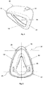
- FIG. 1 shows a perspective side view of a Maskwulstes invention 10 with a support structure - not shown.
- a contact area 14 surrounding an opening 15, a nose bridge area 11, a side area 12 and a base area 13 of the mask bead 10 are illustrated.
- the support region 14 is designed as a sealing lip and surrounds the entire opening 15.
- the mask bead has different wall thicknesses in the nose bridge region 11, in the side region 12 and in the base region 13.
- FIG. 2 shows a schematic plan view of the mask bead 10 according to the invention with a representation of a nose bridge region 11, two side regions 12 and a base region 13 of the mask bead 10.
- the nose bridge region 11 is an area which is located opposite the base region 13. Between the nose bridge region 11 and the base region 13, the two side regions 12 are separated by the opening 15.
- the opening 15 is adapted to at least partially receive a nose of a patient.
- the nose bridge region 11 is a region of the mask bead 10 in which it has a curvature which has an angle of> 180 °.
- the base region 13 is a region of the mask bead 10, which is formed opposite the nose bridge region 11 and has a substantially linear shape.
- the side portion 12 is a portion of the mask bead 10 extending between the nasal bridge portion 11 and the base portion 13.
- the mask bead 10 thus has two side regions 12, which are arranged separated by the opening 15 opposite one another.
- the two side regions 12 have a conical shape to each other.
- the various regions are connected to one another by transition regions 25.
- the transition region 25 between the nasal bridge region 11 and a side region 12 is the region where the angle of the mask bead 10 changes from a curved shape to a linear shape.
- the transition region 25 between the base region and the side region is the region in which the mask bead changes from the conical shape at an angle of more than 90 ° into a linear course.
- the nose bridge area 11, the side area 12 and the base area 13 are formed in an approximate size ratio of 1: 1: 3.
- the size ratios can be chosen differently.
- FIG. 3 Shown is the nose bridge area 11, the side area 12, the base area 13 and the support area 14.
- the support area 14 extends circumferentially around an opening (not shown) of the mask bead 10.
- a mask bead connection 21 is formed, which is adapted to connect the mask bead 10 to a hose system or, for example, a forehead support.
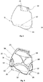
- FIG. 4 shows an axial section in the longitudinal direction of the in the FIGS. 1 to 3
- Masking bead 10 according to the invention shown with a support structure 16 and a support member 19.
- the longitudinal section thus shows an interior view of the mask bead 10 in the applied state in the vertical direction. Shown is the mask bead 10 with the mask bead wall 24, the nose bridge region 11, the side region 12, the base region 13 and the mask bead connection 21.
- the support structure 16 comprises at least two reinforcement points 17, which are respectively arranged in a transition region 25 of the nose bridge region 11 to the side region 12 and the side region 12 to the base region 13, and an arcuate connecting structure 20 which between the reinforcing points 17 is arranged.
- the support structure 16 is formed without contact with the support region 14.
- the support structure 16 is formed integrally with the mask bead wall 24. It has a thicker wall than the mask wall wall 24 surrounding it in the individual areas (Nose bridge area 11, side areas 12, base area 13). In general, the support structure has a 1 10 thicker wall thickness than the surrounding mask bead wall 24.
- the support structure 16 is formed as a thickened sheet strand integrally formed in the mask bead 10.
- the support structure 16 may be rounded, oval or edged.
- a support element 19 is shown, which is arranged in the region of a vertex of the connection structure 20 and extends from the support structure 16 in the form of an hourglass in the direction of the mask bead connection 21.
- the support member 19 is formed integrally with the mask bead wall 24.
- the support element 19 generally has the same wall thickness as the support structure 16. However, the wall thickness of the support element 19 may also differ from the wall thickness of the support structure 16.
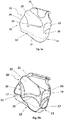
- FIG. 2 shows a perspective side view of the mask bead 10 according to the invention, wherein the mask bead wall 24, the nose bridge region 11, the side region 12, the base region 13 and the support region 14 and the mask bead connection 21 are shown.
- adjustment ranges 22 are shown.
- the adjustment regions 22 are formed by the support structure (not shown) and at least one support element (not shown).
- the adjustment regions 22 have buckling regions 23, which are U-shaped or V-shaped.
- the adjustment regions 22 are formed integrally in the mask bead wall 24 and have the same wall thickness as the mask bead wall 24. However, in a further embodiment, they can also have different wall thicknesses.
- the adjustment regions 22 are configured to form a curvature when pressure is exerted on the mask bead 10, as a result of which the distance between the support structure 16 (not shown) and the mask bead connection 21 is reduced.
- the curvature can be formed circumferentially around the mask bead in the region of the adjustment region 22.
- the adjustment portions 22 have a different shape, so there is a first, larger adjustment range and a second smaller adjustment range.
- the expression of the adjustment regions 22 is determined by the arrangement of the support element 19. In the FIG.
- the mask bead 10 according to the invention is shown, wherein in the present embodiment, the adjustment regions 22 are formed by a support element 19 (not shown) arranged laterally on the connection structure 16.
- FIG. 5b shows a longitudinal section through the in the FIG. 5a Shown are the arched structure 16, the reinforcing points 17 and the connecting structure 20.
- the support member 19 is shown, wherein the support member 19 does not expand from an apex of the connection structure 20 starting hourglass, but from a lateral Section of the arcuate connecting structure 20 is formed.
- the adjustment regions 22 are bounded by the support structure 16, the support element 22 and the mask bead connection 21.
- the adjustment regions 23 may be formed of a more elastic, thinner or different material than the surrounding regions of the mask bead 10.
- the adjustment region 23 may have internal stiffening structures, which may be formed, for example, by different material hardnesses.
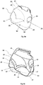
- FIG. 6a 3 shows a further alternative embodiment of the mask bead 10 according to the invention with the mask bead connection 21, the support structure (not shown), the support element (not shown), two bend regions 23 and two adjustment regions 22.
- the first and the second adjustment portion 22 are determined by the position of the - not shown -Ab spalements on the - support structure, not shown.
- the first and second adjustment portions 22 are configured to form a bulge of the mask bead wall 24 under pressure.
- the Einstellberieche each have buckling regions 23, which are formed in the present embodiment v-shaped.
- the buckling regions 23 may also be U-shaped.
- FIG. 6b shows an axial longitudinal section through in the FIG. 6a shown embodiment of the mask bead 10 according to the invention with the support structure 16, the support member 19, two adjustment areas 22 and two buckling areas 23 in not bent state.
- the mask bead 10 according to the invention has the support element 19, which extends in the manner of an hourglass from the support structure 16 in the direction of the mask bead connection 21.
- the support structure 16 has the reinforcement points 17 and an arc-shaped connecting structure 20.
- the support structure 16 has a reduction / reduction of the wall thickness.
- FIG. 6c shows an axial longitudinal section through in the FIGS. 6a and 6b shown embodiment of the mask bead 10 according to the invention with the support structure 16, the support member 19, adjustment areas 22 and two kink areas 23 in kinked state.
- the support structure 16 in FIG. 6b described reduction of the wall thickness and the support member 19 is arranged laterally on the connecting structure 20 of the support structure 16, whereby a first, large adjustment range and a second, smaller adjustment range 22 are formed.
- Shown is the mask bead 10 according to the invention in a bent state, that is, the mask bead 10 is acted upon in the applied state, a pressure.
- Shown is that the mask bead wall 24 is formed curved in this bent state.
- FIG. 7 shows a longitudinal section through an embodiment of a mask bead 10 according to the invention.
- the nose bridge area 11, the side area 12, the base area 13 and the support area 14 are shown. Shown is also the support structure 16.
- the support structure 16 has a wall thickness between 1.8 mm to 2 mm.
- the wall thickness of the support structure 16 may vary.
- a part of the support structure 16, which is formed adjacent to the nasal bridge portion 11 a smaller wall thickness, for example, 1.6 mm, as a part of the support structure 16, for example, 2.0 mm, which is adjacent to the base portion 13, is formed.
- the mask bead 10 has different wall thicknesses.
- the nose bridge region 11 has a wall thickness of 0.2-0.7 mm, in particular 0.35 mm.
- the side region 12 has a smaller wall thickness than the surrounding support structures 16. In the present embodiment, the side region 12 has a wall thickness of 1.6 mm.
- the base region 13 generally has a greater wall thickness than the nose bridge region 11 formed opposite thereto.
- the base area usually has a wall thickness of 0.5 - 1.2 mm.
- the base portion 13 has a wall thickness of 0.6 mm.
- FIG. 8 shows a perspective view of the opening 15 of - Fig. 7
- the mask ridge 10 has a different wall thickness, wherein the difference between the wall thickness of the support structure 16 and the mask ridge wall 24 surrounding it is low is, in particular between 0.2 mm and 0.4 mm.
- FIG. 9 shows a perspective view of the opening 15 of the mask bead 10 according to the invention with the support area 14. Also shown are the nose bridge area 11, the side areas 12 and the base area 13, which are arranged around the opening 15.
- the support region 14 extends circumferentially around the opening 15 and is formed as a sealing lip.
Landscapes
- Health & Medical Sciences (AREA)
- Emergency Medicine (AREA)
- Pulmonology (AREA)
- Engineering & Computer Science (AREA)
- Anesthesiology (AREA)
- Biomedical Technology (AREA)
- Heart & Thoracic Surgery (AREA)
- Hematology (AREA)
- Life Sciences & Earth Sciences (AREA)
- Animal Behavior & Ethology (AREA)
- General Health & Medical Sciences (AREA)
- Public Health (AREA)
- Veterinary Medicine (AREA)
- Respiratory Apparatuses And Protective Means (AREA)
Abstract
Description
- Masken werden im Bereich der Beatmung und der Schlaftherapie eingesetzt, wo ein Patient mittels einer Flow- oder Druckquelle mit Atemgas versorgt wird. Eine Maske stellt die Schnittstelle zwischen Patient und Gerät dar. Sie besteht meistens aus einem Maskenkörper mit einem Maskenwulst und wird mittels einer Bänderung und eventuell mit einer zusätzlichen Stirnabstützung am Kopf des Patienten fixiert. Der Maskenkörper besteht in der Regel aus einem relativ steifen Kunststoff und der Maskenwulst, der am Gesicht, bzw. an Gesichtspartien des Patienten anliegt, bestehend aus einem relativ dünnen, weichen Material, vorzugsweise aus einem hautfreundlichen Silikon, einem thermoplastischen Elastomer (TPE) oder aus Polyurethan und besitzt in der Regel eine Dichtlippe, um eine ausreichende Abdichtung zu gewährleisten und Leckagen zu verhindern.
- Die Funktion eines Maskenwulstes besteht unter anderem darin, das Gewicht des Maskenkörpers sanft gegen das Gesicht abzustützen. Hierfür weist der Maskenwulst eine Festigkeit auf, die es erlaubt, den Maskenkörper abzustützen und dennoch, durch das relativ weiche Material des Maskenwulstes, die empfindlichen Gesichtspartien des Patienten zu schützen.
- Wie eingehend beschrieben werden herkömmliche Maskenwülste aus einem relativ dünnen, weichen Material mit einer geringeren Festigkeit gebildet, um sowohl einem Patienten beim Tragen einer entsprechenden Maske einen höchstmöglichen Komfort bereitzustellen als auch eine hohe Anpassungsfähigkeit des Maskenwulstes an die Gesichtskontur des Patienten zu erzielen.
- Die aus dem Stand der Technik bekannten Lösungen weisen jedoch den Nachteil auf, dass die Verringerung der Festigkeit des Materials des Maskenwulstes auch zu einer Verringerung der Abstützfunktion des Maskenwulstes führt. Somit können zwar durch die Verringerung der Festigkeit des Materials der Komfort und die Anpassbarkeit des Maskenwulstes an die Gesichtskontur des Patienten verbessert werden, gleichzeitig verschlechtert eine Verringerung der Festigkeit jedoch auch die Abstützfunktion des Maskenwulstes.
- Es ist daher Aufgabe der vorliegenden Erfindung, einen Maskenwulst bereitstellen, der sowohl den Tragekomfort für einen Patienten und die Anpassbarkeit des Maskenwulstes an die Gesichtskontur des Patienten verbessert als auch gleichzeitig die Abstützfunktion des Maskenwulstes verbessert.
- Diese Aufgabe wird durch einen Maskenwulst gemäß dem erfindungsgemäßen Anspruch 1 gelöst.
- Gegenstand der vorliegenden Erfindung ist ein Maskenwulst für ein Patienteninterface bestehend aus einem Nasenrückenbereich, mindestens einem Seitenbereich, einem Basisbereich, einem Maskenwulstanschluss und einem Auflagebereich zum Patienten, wobei der Auflagebereich sich ausgehend von den Seitenbereichen und dem Basisbereich sowie dem Nasenrückenbereich zur Öffnung hin erstreckt, wobei der Auflagebereich als Dichtlippe ausgeführt ist, welche die zentrale Öffnung umrandet, die zumindest der Einführung einer Nase des Patienten dient. Der erfindungsgemäßen Maskenwulst ist sowohl für Nasalmasken als auch für Fullfacemasken einsetzbar.
- Der Maskenwulst kann in die Bereiche Nasenrückenbereich, Seitenbereiche und Basisbereich eingeteilt werden.
- Als Nasenrückenbereich wird der Bereich des Maskenwulstes bezeichnet, der eine Wölbung aufweist, die einen Winkel >180° aufweist. Der Nasenrückenbereich weist typischerweise eine Wandstärke von 0,2 - 0,7 mm auf. Der Nasenrückenbereich erstreckt sich in der Regel von dem Auflagebereich in Richtung des Maskenwulstanschlusses.
- Als Basisbereich wird ein Bereich des Maskenwulstes bezeichnet, der an einer, dem Nasenrückenbereich gegenüberliegenden, Seite des Maskenwulstes ausgebildet ist und eine im Wesentlichen lineare Ausprägung aufweist. Beispielsweise weist der Basisbereich eine Wandstärke von 0,5 - 1,2 mm auf. Der Basisbereich erstreckt sich in der Regel von dem Auflagebereich in Richtung des Maskenwulstanschlusses.
- Als Seitenbereich wird jeweils ein Bereich des Maskenwulstes bezeichnet, der sich auf jeder Seite der Öffnung des Maskenwulstes zwischen dem Nasenrückenbereich und dem Basisbereich erstreckt, wobei die beiden Seitenbereiche zueinander eine zulaufende bzw. konische Form aufweisen. Beispielsweise weist der Seitenbereich eine Wandstärke von 1,2 - 2,5 mm auf. Die Seitenbereiche erstrecken sich jeweils von dem Auflagebereich in Richtung des Maskenwulstanschlusses. Optional kann der Maskenwulst eine Doppellippenstruktur aufweisen.
- Der Nasenrückenbereich und der Basisbereich grenzen jeweils an die Seitenbereiche an, wobei zwischen Nasenrückenbereich und Seitenbereichen und Basisbereich und Seitenbereichen jeweils Übergangsbereiche ausgebildet sind. Ein Übergangsbereich ist dabei ein Bereich, in dem sich der Verlauf der Form des Maskenwulstes ändert. Der Übergangsbereich zwischen Nasenrückenbereich und dem jeweiligen angrenzenden Seitenbereich ist der Bereich, in dem der Winkel des Maskenwulstes von einer gebogenen Form, die einen Winkel von über 180° aufweist, in eine lineare Form übergeht. Der Übergangsbereich zwischen Basisbereich und Seitenbereich ist jeweils der Bereich, in dem der Maskenwulst von einer konisch zulaufenden Form in einem Winkel von über 90° in einen linearen Verlauf übergeht.
- Erfindungsgemäß ist der Maskenwulst aus mindestens einem elastischen Material ausgebildet und umfasst mindestens eine Stützstruktur, wobei die Stützstruktur in dem Maskenwulst bereichsweise zum Auflagebereich weisend und bereichsweise zum Maskenwulstanschluss weisend ausgebildet ist. Dabei kann die Stützstruktur in ihrem Verlauf unterschiedliche Abstände zum Auflagebereich aufweisen. Beispielsweise kann die Stützstruktur an einem Scheitelpunkt des Nasenrückenbereichs einen größeren Abstand zum Auflagebereich aufweisen als an einem seitlichen Bereich des Nasenrückenbereichs. Auch kann die Stützstruktur in mindestens einem Seitenbereich des Maskenwulstes mindestens zwei verschiedene Abstände zum Auflagebereich aufweisen. Beispielsweise kann die Stützstruktur in einem mittleren Bereich eines Seitenbereichs einen größeren Abstand zum Auflagebereich aufweisen als an den Übergangspunkten zum Nasenrückenbereich oder zum Basisbereich. Der Auflagebereich kann abweichend von dem Nasenrückenbereich, den Seitenbereichen oder dem Basisbereich beispielsweise eine Wandstärke im Bereich von 0,2 - 0,75 mm aufweisen. Alternativ weist der Auflagebereich die gleiche Wandstärke auf, wie der Nasenrückenbereich, die Seitenbereiche oder der Basisbereich.
- Der Maskenwulst ist aus einem hautfreundlichen Material, bevorzugt aus Silikon in einem Shore-Härtebereich zwischen 35 bis 65 Shore A, bevorzugt 40-60 Shore A, ausgebildet.
- Der Maskenwulst kann einteilig hergestellt werden oder in einem Mehrkomponenten-Spritzgussverfahren, beispielsweise im 2K-Verfahren, hergestellt sein. Bei der Herstellung im 2K-Verfahren wird der Maskenwulst aus Materialien mit verschiedenen Härtegraden hergestellt, dabei wird beispielsweise ein weicheres Material an ein härteres Material angespritzt. Durch die Herstellung im Mehrkomponentenverfahren kann ein Maskenwulst mit unterschiedlichen Materialeigenschaften hergestellt werden, wodurch ein Maskenwulst herstellbar ist, der hinreichend steif und trotzdem nachgiebig ist. Beispielsweise ist die Stützstruktur in einem 2K-Verfahren herstellbar. Der Maskenwulst kann aus mindestens zwei, beispielsweise fünf verschiedenen Materialstärken ausgebildet sein. Der Kontakt der unterschiedlichen Komponenten wird bevorzugt über eine Haftung der Materialien erreicht, alternativ oder zusätzlich können mechanische Kontaktstellen die Haftung verstärken (Formschluss).
- Die Stützstruktur ist in der Regel in dem Maskenwulst integral ausgebildet. Alternativ kann die Stützstruktur als ein auf eine Innen- oder Außenwand des Maskenwulstes aufgebrachtes Element ausgebildet sein. Die Stützstruktur ist in der Regel ausgebildet, eine Wandstärke aufzuweisen, die sich von der Wandstärke des umgebenden Maskenwulstes bzw. der einzelnen Bereiche (Nasenrückenbereich, Seitenbereiche, Basisbereich), unterscheidet. Insbesondere weist die Stützstruktur eine Wandstärke auf, die in einem Bereich zwischen


- Typischerweise ist die Stützstruktur vollständig gefüllt ausgebildet. In einer alternativen Ausführungsform kann die Stützstruktur zumindest teilweise gefüllt ausgebildet sein. Die Stützstruktur kann eine homogen gefüllte Struktur aufweisen. Alternativ kann die Stützstruktur eine interne Formgebung aufweisen, die die Stützfunktion der Stützstruktur unterstützt. Optional kann die Stützstruktur als Dichtstruktur ausgebildet sein, die eingerichtet ist, den Maskenwulst, an dem Auflagebereich gegenüber einem Gesicht eines Patienten abzudichten.
- In einer Weiterbildung der Erfindung umgibt die Stützstruktur die Öffnung zumindest zu zwei Drittel oder vollständig. Bei einer Ausgestaltung, bei der die Stützstruktur zumindest zu zwei Drittel die Öffnung des Maskenwulstes umgibt, weisen in der Regel der Nasenrückenbereich und die Seitenbereiche des Maskenwulstes die Stützstruktur auf, während der Basisbereich des Maskenwulstes stützstrukturfrei ausgebildet ist. Durch die Umrandung der Öffnung des Maskenwulstes mit der Stützstruktur zumindest zu zwei Drittel, kann der Maskenwulst optimal abgestützt werden. Bei der vollständigen Umrandung der Öffnung des Maskenwulstes mit der Stützstruktur ist die Stützstruktur zudem in dem Basisbereich ausgebildet. Die vollständige Umrandung liefert eine besonders gleichmäßige Verteilungsmöglichkeit von Gewicht auf Gesichtsbereiche des Patienten.
- In Ausgestaltung weist die Stützstruktur mindestens zwei Verstärkungspunkte und mindestens eine Verbindungsstruktur zwischen zwei Verstärkungspunkten auf. In der Regel ist die Stützstruktur durchgängig ausgebildet, wobei die Stützstruktur mindestens zwei Verstärkungspunkte und mindestens eine die beiden Verstärkungspunkte verbindende Verbindungstruktur umfasst. Durch die Ausbildung der Stützstruktur wird die Festigkeit des Maskenwulstes verstärkt. Die Verbindungstruktur kann linear oder gebogen ausgebildet sein. Alternativ kann die Verbindungstruktur eine gewellte, gezackte oder geschwungene Struktur aufweisen.
- Die Stützstruktur kann eine durchgehend gleiche Wandstärke aufweisen. In der Regel weist die Stützstruktur in den einzelnen Bereichen unterschiedliche Wandstärken auf. In der Regel weist die Stützstruktur jeweils eine


- In der Regel weist die Stützstruktur zudem eine durchgehend gleiche Breite auf. Die Breite der Stützstruktur ist der Querschnitt der Stützstruktur des Maskenwulstes in angelegtem Zustand in horizontaler Richtung. Optional kann die Breite der Stützstruktur unterschiedlich ausgebildet sein. Beispielsweise kann die Breite der Stützstruktur im Bereich mindestens eines Verstärkungspunktes verringert ausgebildet sein.
- In einer weiteren Ausgestaltung ist die mindestens eine Verbindungsstruktur als Bogen ausgebildet, wobei der Bogen von dem Auflagebereich fortweisend ausgebildet ist. Der Bogen erstreckt sich dabei beispielsweise von einem Verstärkungspunkt über den Nasenrückenbereich zu einem zweiten Verstärkungspunkt. Vorzugsweise sind die Verstärkungspunkte jeweils an einem Übergang zwischen Nasenrückenbereich zu Seitenbereich angeordnet. Optional oder zusätzlich erstreckt sich der Bogen von einem Verstärkungspunkt über den Seitenbereich des Maskenwulstes zu einem weiteren Verstärkungspunkt, der an dem Übergang des Seitenbereichs zum Basisbereich des Maskenwulstes ausgebildet ist. Alternativ oder zusätzlich erstreckt sich der Bogen von dem Verstärkungspunkt am Übergang des Seitenbereichs über den Basisbereich des Maskenwulstes zu einem weiteren Verstärkungspunkt, der an dem Übergang des Basisbereichs zum Seitenbereich des Maskenwulstes ausgebildet ist. Die bogenförmige Ausgestaltung der Verbindungsstruktur ermöglicht eine besonders stabile und gleichmäßige Verteilung des Gewichts des Maskenkörpers. Der Bogen verleiht einem Bereich des Maskenwulstes, über den er sich ausbildet, eine Festigkeit und kann daher auch als festigkeitsgebende Struktur bezeichnet werden.
- In einer Weiterbildung des erfindungsgemäßen Maskenwulstes, sind die Verstärkungspunkte im Maskenwulst im Bereich des Auflagebereichs oder an dem Auflagebereich anliegend angeordnet. Die Verstärkungspunkte sind in der Regel berührungsfrei zu dem Auflagebereich des Maskenwulstes ausgebildet. Durch die berührungsfreie Ausgestaltung liegt die Stützstruktur nicht direkt an das Gesicht des Patienten an, wodurch die Bereiche, die direkt mit dem Patienten in Berührung kommen, mit einem weicheren bzw. dünneren Material versehen werden können. Alternativ können die Verstärkungspunkte der Stützstruktur an den Auflagebereich anliegend bzw. im Auflagebereich ausgebildet sein.
- In einer weiteren Weiterbildung ist ausgehend von mindestens einer Verbindungsstruktur der Stützstruktur ein Abstützelement ausgebildet, dass sich in Richtung des Maskenwulstanschlusses aufweitet. Das Abstützelement ist eingerichtet, den durch das Gewicht des Maskenwulstes auf die Stützstruktur wirkenden Druck im angelegten Zustand des Maskenwulstes abzustützen. Somit wirkt das Abstützelement zusammen mit der Stützstruktur stabilisierend für den Maskenwulst. Das Abstützelement geht in der Regel von der Verbindungsstruktur, die beispielsweise als Bogen ausgebildet ist, ab. Das Abstützelement kann eine sanduhrförmige Struktur aufweisen. Das Abstützelement kann als Abstandselement ausgebildet sein, welches eingerichtet ist, einen Abstand zwischen der Stützstruktur und dem Maskenwulstanschluss bereitzustellen.
- In Ausgestaltung ist das Abstützelement mittig oder seitlich von der Verbindungstruktur ausgehend ausgebildet. Bei einer mittigen Anordnung des Abstützelements erfolgt eine gleichmäßige Ableitung eines Drucks der Stützstruktur. Eine mittige Anordnung des Abstützelements ermöglicht zudem die Ausbildung gleich großer Einstellbereiche. Die Einstellbereiche können u-förmige oder v-förmige Knickbereiche aufweisen. Die mittige Anordnung des Abstützelements ist besonders stabil, wobei der Einstellbereich sowohl in Richtung des Nasenrückenbereichs als auch in Richtung des Basisbereichs gleichmäßig einstellbar bzw. kippbar in Bezug zu einer Senkrechten des Maskenwulstes in angelegtem Zustand ausgebildet ist. Dies bietet den Vorteil, dass der Maskenwulst an eine Gesichtskontur des Patienten, insbesondere eine Nasenrückenform des Patienten, anpassbar ist.
- Eine seitliche Anordnung des Abstützelements ermöglicht die Ausbildung zweier unterschiedlich großer Einstellbereiche. Die Einstellbereiche können u-förmige oder v-förmige Knickbereiche aufweisen. Die seitliche Anordnung des Abstützelements ermöglicht somit eine Ausbildung eines ersten, größeren Einstellbereichs und eines zweiten, kleineren Einstellbereichs, wobei der erste Einstellbereich vorzugsweise im Bereich des Nasenrückenbereichs ausgebildet und der zweite Einstellbereich vorzugsweise im Bereich des Basisbereichs ausgebildet ist. Durch die Ausgestaltung zweier unterschiedlich großer Einstellbereiche kann der Maskenwulst entlang der Senkrecht des Maskenwulstes in angelegtem Zustand unterschiedlich stark gekippt werden. Dies bietet den Vorteil, dass durch den größeren Einstellbereich im Bereich des Nasenrückenbereichs der Maskenwulst in diesem Bereich stärker kippbar ist und damit an eine größere Anzahl an verschiedenen Gesichtskonturen bzw. Nasenrückenkonturen, anpassbar ist.
- In einer erfindungsgemäßen Weiterbildung ist an mindestens einem Übergang der Stützstruktur zu dem Abstützelement mindestens ein Knickbereich ausgebildet. Der Knickbereich kann u-förmig oder v-förmig ausgebildet sein. Der Knickbereich ist vorzugsweise an einem Einstellbereich ausgebildet, sodass durch die Bewegung des Knickbereichs die Einstellung des Einstellbereichs erfolgt. Ein Knicken bzw. Zusammendrücken des Knickbereichs erfolgt zumeist durch das Aufsetzen, Befestigen und Einstellen des Maskenwulstes an dem Patientengesicht. Bei dem Knicken des Knickbereichs wird der Einstellbereich derart zusammengedrückt, dass dieser sich zu der Außenseite des Maskenwulstes hin wölbt. Je größer der Einstellbereich und je größer der Druck, desto größer kann die Wölbung ausfallen. Der Knickbereich kann durch eine Verringerung der Wandstärke der Stützstruktur oder des Abstützelements ausgebildet sein. Alternativ kann der Knickbereich durch eine Federstruktur ausgebildet sein. Alternativ kann der Knickbereich mittels eines weicheren Materials im Vergleich zu dem Material der Stützstruktur oder des Abstützelements ausgebildet sein.
- In einer weiteren Weiterbildung ist mindestens einer der Knickbereiche durch eine Verringerung der Stärke der Stützstruktur ausgebildet. Durch die Verringerung der Wandstärke der Stützstruktur wird ein v-förmige ausgebildeter Knickbereich ausgebildet. Besonders vorteilhaft ist dabei die Ausgestaltung mit einem seitlichen Knickbereich, durch ein seitlich angeordnetes Abstützelement. Alternativ kann mindestens einer der Knickbereiche durch eine Verringerung der Breite der Stützstruktur ausgebildet sein.
- In Ausgestaltung bilden die Stützstruktur und mindestens ein Knickbereich mindestens einen Einstellbereich aus. Der Einstellbereich weist in der Regel eine Wandstärke zwischen 0,2 und 0,7 mm auf, insbesondere zwischen 0,3 und 0,5 mm. Der Knickbereich wird vorzugsweise durch die Stützstruktur und das Abstützelement ausgebildet. Durch die Beweglichkeit des Knickbereichs wird der einstellbare Einstellbereich ausgebildet. Je stärker der Knickbereich ausgebildet ist, desto größer kann der Einstellbereich eingestellt bzw. gekippt werden.
- In einer weiteren Ausgestaltung sind die Verstärkungspunkte am Übergang des Nasenrückenbereichs zum Seitenbereich und/oder am Übergang des Basisbereichs zum Seitenbereich ausgebildet. Alternativ sind die Verstärkungspunkte im Nasenrückenbereich, im Seitenbereich oder im Basisbereich angeordnet. In der Regel umfasst der Maskenwulst zwei bis acht Verstärkungspunkte, vorzugsweise vier Verstärkungspunkte.
- In Ausgestaltung sind die Verstärkungspunkte der Stützstruktur in mindestens einem Seitenbereich angeordnet.
- In weiterer Ausgestaltung ist mindestens eine Verbindungstruktur über den Nasenrückenbereich des Maskenwulstes ausgebildet, wobei die die Verbindungstruktur begrenzenden Verstärkungspunkte an die einem Seitenbereich des Maskenwulstes, separiert durch die Öffnung, angeordnet sind. Die Anordnung der Verstärkungspunkte jeweils seitlich der Öffnung bietet den Vorteil, dass eine stabile Stützstruktur über den Nasenrückenbereich ausgebildet werden kann.
- In einer weiteren Weiterbildung der Erfindung ist mindestens eine Verbindungstruktur über einem Seitenbereich des Maskenwulstes ausgebildet, wobei die die Verbindungstruktur begrenzenden Verstärkungspunkte auf einem gemeinsamen Seitenbereich des Maskenwulstes angeordnet sind. Die Anordnung der Verstärkungspunkte auf einer gemeinsamen Seite bzw. einem gemeinsamen Seitenbereich bietet den Vorteil, dass eine stabile Stützstruktur über einen unempfindlichen Seitenbereich ausgebildet werden kann.
- In Ausgestaltung weist die Stützstruktur jeweils eine 1/12 bis 1/8, insbesondere eine 1/10 stärkere Wandstärke auf, als der jeweilige Bereich, in dem sie ausgebildet ist. Die Stützstruktur kann dabei unterschiedliche Wandstärken aufweisen. Optional weist die Stützstruktur in einem Teil der Stützstruktur, der benachbart zu dem Nasenrückenbereich ausgebildet ist, eine geringere Wandstärke auf, als in einem Teil der Stützstruktur, der benachbart zu dem Basisbereich ausgebildet ist.
- In einer Weiterbildung weist die Stützstruktur eine Wandstärke zwischen 2 mm und 1,8 mm auf und die umgebende Maskenwulstwand weist eine Wandstärke von 1,6 mm auf. Dabei weist die Stützstruktur in dem Teil der Stützstruktur, der benachbart zu dem Nasenrückenbereich ausgebildet ist, eine Wandstärke von 1,8 mm auf und in dem Teil der Stützstruktur, der benachbart zu dem Basisbereich ausgebildet ist, eine Wandstärke von 2 mm.
- In Ausgestaltung weist die Stützstruktur mindestens zwei Verstärkungspunkte und mindestens eine Verbindungsstruktur zwischen zwei Verstärkungspunkten auf, wobei die mindestens eine Verbindungsstruktur als Bogen ausgebildet ist, wobei der Bogen von dem Auflagebereich fortweisend ausgebildet ist.
- In einer Weiterbildung ist an mindestens einem Übergang der Stützstruktur zu dem Abstützelement mindestens ein Knickbereich ausgebildet, wobei die Stützstruktur und der mindestens eine Knickbereich mindestens einen Einstellbereich ausbilden, wobei der Einstellbereich eine Wandstärke zwischen 0,2 mm und 0,7 mm, insbesondere zwischen 0,3 mm und 0,5 mm aufweist.
- Die vorliegende Erfindung betrifft ferner einen Maskenwulst für ein Patienteninterface bestehend aus einem Nasenrückenbereich, mindestens einem Seitenbereich, einem Basisbereich, einem Maskenwulstanschluss und einem Auflagebereich zum Patienten, wobei der Auflagebereich sich ausgehend von den Seitenbereichen und dem Basisbereich sowie dem Nasenrückenbereich zur Öffnung hin erstreckt, wobei der Auflagebereich als Dichtlippe ausgeführt ist, welche die zentrale Öffnung umrandet, die zumindest der Einführung einer Nase des Patienten dient.
- Erfindungsgemäß umfasst der Maskenwulst mindestens eine Stützstruktur und mindestens einen Knickbereich, wobei die Stützstruktur und der mindestens eine Knickbereich mindestens einen Einstellbereich ausbilden, wobei der Einstellbereich eine Wandstärke zwischen 0,2 und 0,7, insbesondere zwischen 0,3 und 0,5 mm aufweist.
- Die vorliegende Erfindung betrifft des Weiteren einen Maskenwulst für ein Patienteninterface bestehend aus einem Nasenrückenbereich, mindestens einem Seitenbereich, einem Basisbereich, einem Maskenwulstanschluss und einem Auflagebereich zum Patienten, wobei der Auflagebereich sich ausgehend von den Seitenbereichen und dem Basisbereich sowie dem Nasenrückenbereich zur Öffnung hin erstreckt, wobei der Auflagebereich als Dichtlippe ausgeführt ist, welche die zentrale Öffnung umrandet, die zumindest der Einführung einer Nase des Patienten dient.
- Erfindungsgemäß umfasst der Maskenwulst mindestens eine Stützstruktur, wobei die Stützstruktur eine Wandstärke zwischen 2 mm und 1,8 mm aufweist, der Nasenrückenbereich eine Wandstärke von 0,2 - 0,7 mm, insbesondere 0,35 mm aufweist, der Basisbereich eine Wandstärke von 0,5 - 1,2 mm, insbesondere 0,6 mm aufweist und der Seitenbereich eine Wandstärke von 1,2 - 2,5 mm, insbesondere von 1,6 mm aufweist.
- Im Folgenden werden anhand von stark vereinfachten schematischen Darstellungen bevorzugte Ausführungsbeispiele der Erfindung näher erläutert. Es zeigt:
- Fig. 1
- eine perspektivische Seitenansicht eines erfindungsgemäßen Maskenwulstes mit einer -nicht gezeigten- Stützstruktur.
- Fig. 2
- eine schematische Draufsicht auf den erfindungsgemäßen Maskenwulst mit einer Darstellung eines Nasenrückenbereichs, zwei Seitenbereichen und einem Basisbereich,
- Fig. 3
- zeigt eine Seitenansicht des erfindungsgemäßen Maskenwulstes,
- Fig. 4
- zeigt einen Längsschnitt des erfindungsgemäßen Maskenwulstes mit einer Stützstruktur und einem Abstützelement,
- Fig. 5a
- zeigt eine Seitenansicht auf eine weitere Ausführungsform des erfindungsgemäßen Maskenwulstes mit der -nicht sichtbaren - Stützstruktur, dem -nicht sichtbaren -Abstützelement, zwei Einstellbereichen und zwei Knickbereichen,
- Fig. 5b
- zeigt einen Längsschnitt durch die in der
Figur 5a gezeigten Ausführungsform des erfindungsgemäßen Maskenwulstes mit der Stützstruktur, dem Abstützelement, zwei Knickbereichen und zwei Einstellbereichen, - Fig. 6a
- zeigt eine weitere alternative Ausführungsform des erfindungsgemäßen Maskenwulstes mit der -nicht gezeigten- Stützstruktur, dem -nicht gezeigten-Abstützelement, zwei Knickbereichen und zwei Einstellbereichen,
- Fig. 6b
- zeigt einen Längsschnitt durch die in der
Figur 6a gezeigten Ausführungsform des erfindungsgemäßen Maskenwulstes mit der Stützstruktur, dem Abstützelement, zwei Einstellbereichen sowie zwei Knickbereichen in nicht genicktem Zustand, - Fig. 6c
- zeigt einen Längsschnitt durch die in der
Figur 6a und 6b gezeigten Ausführungsform des erfindungsgemäßen Maskenwulstes mit der Stützstruktur, dem Abstützelement, zwei Einstellbereichen sowie zwei Knickbereichen in genicktem Zustand, - Fig. 7
- zeigt einen Längsschnitt durch eine Ausführungsform eines erfindungsgemäßen Maskenwulstes,
- Fig. 8
- zeigt eine perspektivische Ansicht auf eine Öffnung des erfindungsgemäßen Maskenwulstes,
- Fig. 9
- zeigt eine perspektivische Ansicht auf die Öffnung des erfindungsgemäßen Maskenwulstes mit einem Auflagebereich.
- In den Figuren weisen dieselben konstruktiven Elemente jeweils dieselben Bezugsziffern auf.
-
Figur 1 zeigt eine perspektivische Seitenansicht eines erfindungsgemäßen Maskenwulstes 10 mit einer - nicht gezeigten - Stützstruktur. Dabei sind ein, eine Öffnung 15 umgebender Auflagebereich 14, ein Nasenrückenbereich 11, ein Seitenbereich 12 sowie ein Basisbereich 13 des Maskenwulstes 10 dargestellt. Der Auflagebereich 14 ist als Dichtlippe ausgebildet und umrandet die gesamte Öffnung 15. Der Maskenwulst weist im Nasenrückenbereich 11, im Seitenbereich 12 und im Basisbereich 13 unterschiedliche Wandstärken auf. -
Figur 2 zeigt eine schematische Draufsicht auf den erfindungsgemäßen Maskenwulst 10 mit einer Darstellung eines Nasenrückenbereichs 11, zwei Seitenbereichen 12 und einem Basisbereich 13 des Maskenwulstes 10. Der Nasenrückenbereich 11 ist ein Bereich, der sich gegenüberliegend dem Basisbereich 13 befindet. Zwischen dem Nasenrückenbereich 11 und dem Basisbereich 13 sind separiert durch die Öffnung 15 jeweils die beiden Seitenbereiche 12 angeordnet. Die Öffnung 15 ist eingerichtet, zumindest teilweise eine Nase eines Patienten aufzunehmen. - Der Nasenrückenbereich 11 ist ein Bereich des Maskenwulstes 10, in dem dieser eine Wölbung aufweist, die einen Winkel > 180° aufweist. Der Basisbereich 13 ist ein Bereich des Maskenwulstes 10, der dem Nasenrückenbereich 11 gegenüberliegend ausgebildet ist und eine im Wesentlichen lineare Ausprägung aufweist. Der Seitenbereich 12 ist ein Bereich des Maskenwulstes 10, der sich zwischen dem Nasenrückenbereich 11 und dem Basisbereich 13 erstreckt. Der Maskenwulst 10 weist somit zwei Seitenbereiche 12 auf, die separiert durch die Öffnung 15 gegenüberliegend zueinander angeordnet sind. Die beiden Seitenbereiche 12 weisen zueinander eine konische Form auf.
- Die verschiedenen Bereiche (Nasenrückenbereich 11, Seitenbereiche 12 und Basisbereich 13) sind durch Übergangsbereiche 25 miteinander verbunden. Der Übergangsbereich 25 zwischen dem Nasenrückenbereich 11 und einem Seitenbereich 12 ist der Bereich, an dem der Winkel des Maskenwulstes 10 von einer gebogenen Form in eine lineare Form übergeht. Der Übergangsbereich 25 zwischen Basisbereich und Seitenbereich ist der Bereich in dem der Maskenwulst von der konisch verlaufenden Form in einem Winkel von über 90° in einen linearen Verlauf übergeht.
- Insgesamt sind in der vorliegenden Ausführungsform der Nasenrückenbereich 11, die Seitenbereich 12 und der Basisbereich 13 in einem ungefähren Größenverhältnis von 1:1:3 ausgebildet. Optional können die Größenverhältnisse anders gewählt sein.
-
Figur 3 zeigt eine Seitenansicht des erfindungsgemäßen Maskenwulstes 10. Gezeigt ist der Nasenrückenbereich 11, der Seitenbereich 12, der Basisbereich 13 und der Auflagebereich 14. Der Auflagebereich 14 erstreckt sich umlaufend um eine - nicht gezeigte - Öffnung des Maskenwulstes 10. Gegenüber dem Auflagebereich 14 ist ein Maskenwulstanschluss 21 ausgebildet, der eingerichtet ist, den Maskenwulst 10 an ein Schlauchsystem oder beispielsweise eine Stirnstütze anzuschließen. -
Figur 4 zeigt einen axialen Schnitt in Längsrichtung des in denFiguren 1 bis 3 gezeigten erfindungsgemäßen Maskenwulstes 10 mit einer Stützstruktur 16 und einem Abstützelement 19. Der Längsschnitt zeigt somit eine Innenansicht des Maskenwulstes 10 in angelegtem Zustand in senkrechter Richtung. Dargestellt ist der Maskenwulst 10 mit der Maskenwulstwand 24, dem Nasenrückenbereich 11, dem Seitenbereich 12, dem Basisbereich 13 und dem Maskenwulstanschluss 21. - In der vorliegenden Ausführungsform des erfindungsgemäßen Maskenwulstes 10 umfasst die Stützstruktur 16 mindestens zwei Verstärkungspunkte 17, die jeweils in einem Übergangsbereich 25 des Nasenrückenbereichs 11 zum Seitenbereich 12 bzw. des Seitenbereichs 12 zum Basisbereich 13 angeordnet sind, sowie eine als Bogen ausgeformte Verbindungsstruktur 20, die zwischen den Verstärkungspunkten 17 angeordnet ist. Die Stützstruktur 16 ist berührungsfrei zu dem Auflagebereich 14 ausgebildet. Die Stützstruktur 16 ist in die Maskenwulstwand 24 integriert ausgebildet. Sie weist eine stärkere Wandstärke auf, als die sie umgehende Maskenwulstwand 24 in den einzelnen Bereichen (Nasenrückenbereich 11, Seitenbereiche 12, Basisbereich 13). In der Regel weist die Stützstruktur eine

- In der
Figur 4 ist ferner ein Abstützelement 19 dargestellt, welches im Bereich eines Scheitelpunktes der Verbindungsstruktur 20 angeordnet ist und sich ausgehend von der Stützstruktur 16 sanduhrförmig in Richtung des Maskenwulstanschlusses 21 erstreckt. In der vorliegenden Ausführungsform ist das Abstützelement 19 in die Maskenwulstwand 24 integriert ausgebildet. Das Abstützelement 19 weist in der Regel die gleiche Wandstärke wie die Stützstruktur 16 auf. Die Wandstärke des Abstützelements 19 kann sich jedoch auch von der Wandstärke der Stützstruktur 16 unterscheiden. - In der
Figur 5a ist eine perspektivische Seitenansicht des erfindungsgemäßen Maskenwulstes 10 dargestellt, wobei die Maskenwulstwand 24, der Nasenrückenbereich 11, der Seitenbereich 12, der Basisbereich 13 sowie der Auflagebereich 14 und der Maskenwulstanschluss 21 gezeigt sind. - Ferner sind Einstellbereiche 22 dargestellt. Die Einstellbereiche 22 werden durch die - nicht gezeigte - Stützstruktur und mindestens ein - nicht gezeigtes - Abstützelement gebildet. Die Einstellbereiche 22 weisen Knickbereiche 23 auf, die u- förmig oder v-förmig ausgebildet sind.
- Die Einstellbereiche 22 sind in der Maskenwulstwand 24 integriert ausgebildet und weisen dieselbe Wandstärke auf, wie die Maskenwulstwand 24. Sie können in einer weiteren Ausführungsform jedoch auch unterschiedliche Wandstärken aufweisen. Die Einstellbereiche 22 sind eingerichtet, bei einer Druckausübung auf den Maskenwulst 10 eine Wölbung auszubilden, wodurch der Abstand zwischen der -nicht gezeigten - Stützstruktur 16 und dem Maskenwulstanschluss 21 verringert wird. Die Wölbung kann umlaufend um den Maskenwulst im Bereich des Einstellbereichs 22 ausgebildet sein. In der vorliegenden Ausführungsform weisen die Einstellbereiche 22 eine unterschiedliche Ausprägung aus, so gibt es einen ersten, größeren Einstellbereich und einen zweiten kleineren Einstellbereich. Die Ausprägung der Einstellbereiche 22 ist durch die Anordnung des Abstützelements 19 bedingt. In der
Figur 5a ist somit der erfindungsgemäße Maskenwulst 10 dargestellt, wobei in der vorliegenden Ausführungsform die Einstellbereiche 22 durch ein - nicht gezeigtes - seitlich an der Verbindungsstruktur 16 angeordnetes Abstützelement 19 ausgebildet werden. Das Abstützelement 19 gibt zusammen mit der Stützstruktur 16 die Form des Knickbereichs 23 vor. -
Figur 5b zeigt einen Längsschnitt durch die in derFigur 5a gezeigten Ausführungsform des erfindungsgemäßen Maskenwulstes 10. Dargestellt sind die gewölbeförmige Struktur 16, die die Verstärkungspunkte 17 und die Verbindungsstruktur 20. Zudem ist das Abstützelement 19 dargestellt, wobei sich das Abstützelement 19 nicht von einem Scheitelpunkt der Verbindungsstruktur 20 ausgehend sanduhrförmig aufweitet, sondern von einem seitlichen Abschnitt der bogenförmig ausgebildeten Verbindungsstruktur 20 ausgebildet ist. Die Einstellbereiche 22 werden durch die Stützstruktur 16, das Abstützelement 22 und den Maskenwulstanschluss 21 begrenzt. Die Einstellbereiche 23 können aus einem elastischeren, dünneren oder anderen Material ausgebildet sein, als die diese umgebenen Bereiche des Maskenwulstes 10. Die Einstellbereich 23 können über interne Versteifungsstrukturen verfügen, die beispielsweise durch unterschiedliche Materialhärten ausgebildet sein können. -
Figur 6a zeigt eine weitere alternative Ausführungsform des erfindungsgemäßen Maskenwulstes 10 mit dem Maskenwulstanschluss 21, der -nicht gezeigten- Stützstruktur, dem - nicht gezeigten - Abstützelement, zwei Knickbereichen 23 und zwei Einstellbereichen 22. - Dargestellt ist eine Ausführungsform mit zwei unterschiedlich großen Einstellbereichen 22, einem ersten und einem zweiten Einstellbereich 22. Der erste und der zweite Einstellbereich 22 werden durch die Lage des - nicht gezeigten -Abstützelements an der - nicht gezeigten -Stützstruktur bestimmt. Der erste und der zweite Einstellbereich 22 sind eingerichtet, unter Druck eine Wölbung der Maskenwulstwand 24 auszubilden. Die Einstellberieche weisen jeweils Knickbereiche 23 auf, die in der vorliegende Ausführungsform v-förmig ausgebildet sind. Optional können die Knickbereiche 23 auch u-förmig ausgebildet sein.
-
Figur 6b zeigt einen axialen Längsschnitt durch die in derFigur 6a gezeigten Ausführungsform des erfindungsgemäßen Maskenwulstes 10 mit der Stützstruktur 16, dem Abstützelement 19, zwei Einstellbereichen 22 sowie zwei Knickbereichen 23 in nicht genicktem Zustand. Der erfindungsgemäße Maskenwulst 10 weist das Abstützelement 19 auf, welches sich sanduhrförmig von der Stützstruktur 16 in Richtung des Maskenwulstanschlusses 21 erstreckt. Die Stützstruktur 16 weist die Verstärkungspunkte 17 sowie eine bogenförmig ausgestaltete Verbindungsstruktur 20 auf. Am Übergang der Stützstruktur 16 zum Abstützelement 19 wird der Knickbereich 23 ausgebildet. Im Bereich des Knickbereichs 23 weist die Stützstruktur 16 eine Verringerung/Reduzierung der Wandstärke auf. Durch die Reduzierung der Wandstärke der Stützstruktur 16 kann der Knickbereich 23 vergrößert werden, sodass der durch den Knickbereich 23 gebildete Einstellbereich 22 vergrößert wird. -
Figur 6c zeigt einen axialen Längsschnitt durch die in derFigur 6a und 6b gezeigten Ausführungsform des erfindungsgemäßen Maskenwulstes 10 mit der Stützstruktur 16, dem Abstützelement 19, Einstellbereichen 22 sowie zwei Knickbereichen 23 in geknicktem Zustand. Dabei weist die Stützstruktur 16 die inFigur 6b beschriebene Reduzierung der Wandstärke auf und das Abstützelement 19 ist seitlich an der Verbindungsstruktur 20 der Stützstruktur 16 angeordnet, wodurch ein erster, großer Einstellbereich und ein zweiter, kleinerer Einstellbereich 22 ausgebildet sind. Gezeigt ist der erfindungsgemäße Maskenwulst 10 in geknicktem Zustand, d.h. auf den Maskenwulst 10 ist in angelegtem Zustand ein Druck beaufschlagt. Gezeigt ist, dass die Maskenwulstwand 24 in diesem geknickten Zustand gewölbt ausgebildet ist. Somit ist der Abstand zwischen der Stützstruktur 16 und dem Maskenwulstanschluss 21 verringert worden, sodass die überschüssige Maskenwulstwand 24 nach außen gewölbt wird. -
Figur 7 zeigt einen Längsschnitt durch eine Ausführungsform eines erfindungsgemäßen Maskenwulstes 10. Dabei sind der Nasenrückenbereich 11, der Seitenbereich 12, der Basisbereich 13 sowie der Auflagebereich 14 dargestellt. Gezeigt ist auch die Stützstruktur 16. - In der vorliegenden Ausführungsform weist die Stützstruktur 16 eine Wandstärke zwischen 1,8 mm bis 2 mm auf. Die Wandstärke der Stützstruktur 16 kann dabei variieren. So kann ein Teil der Stützstruktur 16, der benachbart zu dem Nasenrückenbereich 11 ausgebildet ist, eine geringere Wandstärke, beispielsweise 1,6 mm aufweisen, als ein Teil der Stützstruktur 16, mit beispielsweise 2,0 mm, der benachbart zum Basisbereich 13, ausgebildet ist.
- Wie in der
Figur 7 dargestellt weist der Maskenwulst 10 unterschiedliche Wandstärken auf. So weist der Nasenrückenbereich 11 eine Wandstärke von 0,2 - 0,7 mmm, insbesondere von 0,35 mm auf. Der Seitenbereich 12 weist eine geringere Wandstärke auf, als die ihn umgebenden Stützstrukturen 16. In der vorliegenden Ausführungsform weist der Seitenbereich 12 eine Wandstärke von 1,6 mm auf. - Der Basisbereich 13 weist in der Regel eine stärkere Wandstärke als diesem gegenüberliegen ausgebildeten Nasenrückenbereich 11 auf. Der Basisbereich weist in der Regel eine Wandstärke von 0,5 - 1,2 mm auf. In der vorliegenden Ausführungsform weist der Basisbereich 13 eine Wandstärke von 0,6 mm auf.
-
Figur 8 zeigt eine perspektivische Ansicht auf die Öffnung 15 des - inFig. 7 gezeigten - erfindungsgemäßen Maskenwulstes 10. Dargestellt ist der Nasenrückenbereich 11, sowie die Seitenbereiche 12 und der Basisbereich 13 sowie der Auflagebereich 14. Der Maskenwulst 10 weist eine unterschiedliche Wandstärke auf, wobei die Differenz zwischen der Wandstärke der Stützstruktur 16 und der diese umgebenden Maskenwulstwand 24 gering ist, insbesondere zwischen 0,2 mm und 0,4 mm beträgt. -
Figur 9 zeigt eine perspektivische Ansicht auf die Öffnung 15 des erfindungsgemäßen Maskenwulstes 10 mit dem Auflagebereich 14. Dargestellt sind zudem der Nasenrückenbereich 11, die Seitenbereiche 12 sowie der Basisbereich 13, die um die Öffnung 15 angeordnet sind. Der Auflagebereich 14 erstreckt sich umlaufend um die Öffnung 15 und ist als Dichtlippe ausgebildet. -
- 10
- Maskenwulst
- 11
- Nasenrückenbereich
- 12
- Seitenbereich
- 13
- Basisbereich
- 14
- Auflagebereich
- 15
- Öffnung
- 16
- Stützstruktur
- 17
- Verstärkungspunkte
- 18
- Verbindungsstruktur
- 19
- Abstützelement
- 20
- Bogen
- 21
- Maskenwulstanschluss
- 22
- Einstellbereich
- 23
- Knickbereich
- 24
- Maskenwulstwand
- 25
- Übergangsbereich
Claims (15)
- Maskenwulst (10) für ein Patienteninterface bestehend aus einem Nasenrückenbereich (11), mindestens einem Seitenbereich (12), einem Basisbereich (13), einem Maskenwulstanschluss (21) und einem Auflagebereich (14) zum Patienten, wobei der Auflagebereich (14) sich ausgehend von den Seitenbereichen (12) und dem Basisbereich (13) sowie dem Nasenrückenbereich (11) zur Öffnung (15) hin erstreckt, wobei der Auflagebereich (14) als Dichtlippe ausgeführt ist, welche die zentrale Öffnung (15) umrandet, die zumindest der Einführung einer Nase des Patienten dient, dadurch gekennzeichnet, dass der Maskenwulst (10) aus mindestens einem elastischen Material ausgebildet ist und mindestens eine Stützstruktur (16) umfasst, wobei die Stützstruktur (16) in dem Maskenwulst (10) bereichsweise zum Auflagebereich (14) weisend und bereichsweise zum Maskenwulstanschluss (21) weisend ausgebildet ist.
- Maskenwulst (10) nach einem der voranstehenden Ansprüche, dadurch gekennzeichnet, dass die Stützstruktur (16) die Öffnung (15) zumindest zu zwei Drittel oder vollständig umgibt.
- Maskenwulst (10) nach einem der voranstehenden Ansprüche, dadurch gekennzeichnet, dass die Stützstruktur (16) mindestens zwei Verstärkungspunkte (17) und mindestens eine Verbindungsstruktur (18) zwischen zwei Verstärkungspunkten (17) aufweist.
- Maskenwulst (10) nach einem der voranstehenden Ansprüche, dadurch gekennzeichnet, dass die mindestens eine Verbindungsstruktur (18) als Bogen (20) ausgebildet ist, wobei der Bogen (20) von dem Auflagebereich (14) fortweisend ausgebildet ist.
- Maskenwulst (10) nach einem der voranstehenden Ansprüche, dadurch gekennzeichnet, dass die Verstärkungspunkte (17) im Maskenwulst (10) im Bereich des Auflagebereichs (14) oder an dem Auflagebereich (14) anliegend angeordnet sind.
- Maskenwulst (10) nach einem der voranstehenden Ansprüche, dadurch gekennzeichnet, dass ausgehend von mindestens einer Verbindungsstruktur (18) der Stützstruktur (16) ein Abstützelement (19) ausgebildet ist, das sich in Richtung eines Maskenwulstanschlusses (21) aufweitet.
- Maskenwulst (10) nach einem der voranstehenden Ansprüche, dadurch gekennzeichnet, dass das Abstützelement (19) mittig oder seitlich von der Verbindungsstruktur (18) ausgehend ausgebildet ist.
- Maskenwulst (10) nach einem der voranstehenden Ansprüche, dadurch gekennzeichnet, dass an mindestens einem Übergang der Stützstruktur (16) zu dem Abstützelement (19) mindestens ein Knickbereich (23) ausgebildet ist.
- Maskenwulst (10) nach einem der voranstehenden Ansprüche, dadurch gekennzeichnet, dass mindestens einer der Knickbereiche (23) durch eine Verringerung der Stärke der Stützstruktur (16) ausgebildet ist.
- Maskenwulst (10) nach einem der voranstehenden Ansprüche, dadurch gekennzeichnet, dass die Stützstruktur (16) und mindestens ein Knickbereich (23) mindestens einen Einstellbereich (22) ausbilden.
- Maskenwulst (10) nach einem der voranstehenden Ansprüche, dadurch gekennzeichnet, dass die Verstärkungspunkte (17) am Übergang des Nasenrückenbereichs (11) zum Seitenbereich (12) und/oder am Übergang des Basisbereichs (13) zum Seitenbereich (12) ausgebildet sind.
- Maskenwulst (10) nach einem der voranstehenden Ansprüche, dadurch gekennzeichnet, dass die Verstärkungspunkte (17) der Stützstruktur (16) in mindestens einem Seitenbereich (12) angeordnet sind.
- Maskenwulst (10) nach einem der voranstehenden Ansprüche, dadurch gekennzeichnet, dass mindestens eine Verbindungsstruktur (18) über den Nasenrückenbereich (11) des Maskenwulstes (10) ausgebildet ist, wobei die die Verbindungsstruktur (18) begrenzenden Verstärkungspunkte (17) an je einem Seitenbereich (12) des Maskenwulstes (10) separiert durch die Öffnung (15) angeordnet sind.
- Maskenwulst (10) nach einem der voranstehenden Ansprüche, dadurch gekennzeichnet, dass mindestens eine Verbindungsstruktur (18) über einem Seitenbereich (12) des Maskenwulstes (10) ausgebildet ist, wobei die die Verbindungsstruktur (18) begrenzenden Verstärkungspunkte (17) auf einem gemeinsamen Seitenbereich (12) des Maskenwulstes (10) angeordnet sind.
- Maskenwulst (10) für ein Patienteninterface bestehend aus einem Nasenrückenbereich (11), mindestens einem Seitenbereich (12), einem Basisbereich (13), einem Maskenwulstanschluss (21) und einem Auflagebereich (14) zum Patienten, wobei der Auflagebereich (14) sich ausgehend von den Seitenbereichen (12) und dem Basisbereich (13) sowie dem Nasenrückenbereich (11) zur Öffnung (15) hin erstreckt, wobei der Auflagebereich (14) als Dichtlippe ausgeführt ist, welche die zentrale Öffnung (15) umrandet, die zumindest der Einführung einer Nase des Patienten dient, dadurch gekennzeichnet, dass der Maskenwulst (10) mindestens eine Stützstruktur (16) umfasst, wobei die Stützstruktur (16) eine Wandstärke zwischen 2 mm und 1,8 mm aufweist, der Nasenrückenbereich eine Wandstärke von 0,2 - 0,7 mm, insbesondere 0,35 mm aufweist, der Basisbereich eine Wandstärke von 0,5 - 1,2 mm, insbesondere 0,6 mm aufweist und der Seitenbereich eine Wandstärke von 1,2 - 2,5 mm, insbesondere von 1,6 mm aufweist.
Applications Claiming Priority (1)
| Application Number | Priority Date | Filing Date | Title |
|---|---|---|---|
| DE102018002998 | 2018-04-12 |
Publications (2)
| Publication Number | Publication Date |
|---|---|
| EP3552650A1 true EP3552650A1 (de) | 2019-10-16 |
| EP3552650B1 EP3552650B1 (de) | 2021-06-23 |
Family
ID=66175266
Family Applications (1)
| Application Number | Title | Priority Date | Filing Date |
|---|---|---|---|
| EP19168981.9A Active EP3552650B1 (de) | 2018-04-12 | 2019-04-12 | Maskenwulst für ein patienteninterface |
Country Status (4)
| Country | Link |
|---|---|
| US (2) | US11679220B2 (de) |
| EP (1) | EP3552650B1 (de) |
| CN (1) | CN110368565B (de) |
| DE (1) | DE102019109752A1 (de) |
Families Citing this family (4)
| Publication number | Priority date | Publication date | Assignee | Title |
|---|---|---|---|---|
| USD784516S1 (en) | 2015-09-25 | 2017-04-18 | Fisher & Paykel Healthcare Limited | Face mask frame |
| USD800895S1 (en) | 2015-09-25 | 2017-10-24 | Fisher & Paykel Healthcare Limited | Face mask cushion |
| USD784515S1 (en) | 2015-09-25 | 2017-04-18 | Fisher & Paykel Healthcare Limited | Headgear |
| US11426551B1 (en) | 2020-06-23 | 2022-08-30 | Lisa M. Butler, Esquire | Nasal ventilation mask |
Citations (11)
| Publication number | Priority date | Publication date | Assignee | Title |
|---|---|---|---|---|
| WO2001062326A1 (de) * | 2000-02-25 | 2001-08-30 | MAP Medizintechnik für Arzt und Patient GmbH & Co. KG | Dichtlippeneinrichtung für eine atemmaske, atemmaske sowie verfahren und formwerkzeug zur herstellung derselben |
| US20020148472A1 (en) * | 1999-05-12 | 2002-10-17 | Respironics, Inc. | Low contact nasal mask and system using same |
| DE102007057091A1 (de) * | 2006-12-06 | 2008-06-12 | Weinmann Geräte für Medizin GmbH + Co. KG | Atemmaske mit einem Füllkörper sowie Herstellungsverfahren |
| EP1982740A2 (de) * | 2007-04-19 | 2008-10-22 | Resmed Limited | Polster und Mechanismus zur Anbringung des Polsters an einem Rahmen für eine Patientenschnittstelle |
| US20120138062A1 (en) * | 2004-11-05 | 2012-06-07 | Koninklijke Philips Electronics N.V. | Respiratory mask seal and mask using same |
| DE102013019149A1 (de) * | 2012-11-29 | 2014-06-05 | Weinmann Geräte für Medizin GmbH + Co. KG | Maskenwulst für ein Patienteninterface |
| US20140283842A1 (en) * | 2011-04-15 | 2014-09-25 | Fisher & Paykel Healthcare Limited | Interface comprising a nasal sealing portion |
| WO2014183167A1 (en) * | 2013-05-14 | 2014-11-20 | Resmed Limited | Oro-nasal patient interface |
| WO2015020535A1 (en) * | 2013-08-05 | 2015-02-12 | Fisher & Paykel Healthcare Limited | Seal for a patient interface, interface assemblies and aspects thereof |
| WO2016032343A1 (en) * | 2014-08-25 | 2016-03-03 | Fisher & Paykel Healthcare Limited | Respiratory mask and related portions, components or sub-assemblies |
| WO2017049360A1 (en) * | 2015-09-23 | 2017-03-30 | Resmed Limited | Patient interface with a seal-forming structure having varying thickness |
Family Cites Families (6)
| Publication number | Priority date | Publication date | Assignee | Title |
|---|---|---|---|---|
| DE20017940U1 (de) * | 2000-10-19 | 2000-12-28 | MAP Medizintechnik für Arzt und Patient GmbH & Co KG, 82152 Planegg | Atemmaske zur Zufuhr eines Atemgases zu einem Maskenanwender sowie Ableitungseinrichtung zur Ableitung von Atemgas |
| WO2006074515A1 (en) * | 2005-01-12 | 2006-07-20 | Resmed Limited | Respiratory masks with gusseted cushions |
| US8245711B2 (en) * | 2005-08-15 | 2012-08-21 | Ric Investments, Llc | Patient interface with adjustable cushion |
| WO2010071453A1 (en) * | 2008-12-17 | 2010-06-24 | Fisher & Paykel Healthcare Limited | Respiratory mask sealing interface |
| GB2562337B (en) * | 2011-07-01 | 2019-02-06 | Fisher & Paykel Healthcare Ltd | Nasal mask interface assembly |
| CN104587580B (zh) * | 2015-02-05 | 2018-03-02 | 深圳瑞之谷医疗科技有限公司 | 面罩 |
-
2019
- 2019-04-10 US US16/380,313 patent/US11679220B2/en active Active
- 2019-04-12 EP EP19168981.9A patent/EP3552650B1/de active Active
- 2019-04-12 CN CN201910292082.4A patent/CN110368565B/zh active Active
- 2019-04-12 DE DE102019109752.5A patent/DE102019109752A1/de active Pending
-
2023
- 2023-05-15 US US18/317,275 patent/US12478754B2/en active Active
Patent Citations (11)
| Publication number | Priority date | Publication date | Assignee | Title |
|---|---|---|---|---|
| US20020148472A1 (en) * | 1999-05-12 | 2002-10-17 | Respironics, Inc. | Low contact nasal mask and system using same |
| WO2001062326A1 (de) * | 2000-02-25 | 2001-08-30 | MAP Medizintechnik für Arzt und Patient GmbH & Co. KG | Dichtlippeneinrichtung für eine atemmaske, atemmaske sowie verfahren und formwerkzeug zur herstellung derselben |
| US20120138062A1 (en) * | 2004-11-05 | 2012-06-07 | Koninklijke Philips Electronics N.V. | Respiratory mask seal and mask using same |
| DE102007057091A1 (de) * | 2006-12-06 | 2008-06-12 | Weinmann Geräte für Medizin GmbH + Co. KG | Atemmaske mit einem Füllkörper sowie Herstellungsverfahren |
| EP1982740A2 (de) * | 2007-04-19 | 2008-10-22 | Resmed Limited | Polster und Mechanismus zur Anbringung des Polsters an einem Rahmen für eine Patientenschnittstelle |
| US20140283842A1 (en) * | 2011-04-15 | 2014-09-25 | Fisher & Paykel Healthcare Limited | Interface comprising a nasal sealing portion |
| DE102013019149A1 (de) * | 2012-11-29 | 2014-06-05 | Weinmann Geräte für Medizin GmbH + Co. KG | Maskenwulst für ein Patienteninterface |
| WO2014183167A1 (en) * | 2013-05-14 | 2014-11-20 | Resmed Limited | Oro-nasal patient interface |
| WO2015020535A1 (en) * | 2013-08-05 | 2015-02-12 | Fisher & Paykel Healthcare Limited | Seal for a patient interface, interface assemblies and aspects thereof |
| WO2016032343A1 (en) * | 2014-08-25 | 2016-03-03 | Fisher & Paykel Healthcare Limited | Respiratory mask and related portions, components or sub-assemblies |
| WO2017049360A1 (en) * | 2015-09-23 | 2017-03-30 | Resmed Limited | Patient interface with a seal-forming structure having varying thickness |
Also Published As
| Publication number | Publication date |
|---|---|
| US12478754B2 (en) | 2025-11-25 |
| CN110368565A (zh) | 2019-10-25 |
| US11679220B2 (en) | 2023-06-20 |
| US20190314594A1 (en) | 2019-10-17 |
| CN110368565B (zh) | 2024-04-26 |
| EP3552650B1 (de) | 2021-06-23 |
| US20230277796A1 (en) | 2023-09-07 |
| DE102019109752A1 (de) | 2019-10-17 |
Similar Documents
| Publication | Publication Date | Title |
|---|---|---|
| EP3552650B1 (de) | Maskenwulst für ein patienteninterface | |
| EP2266652B1 (de) | Dichtlippeneinrichtung für eine Atemmaske | |
| EP3000500B1 (de) | Maskenkissen für eine vollgesichtsmaske | |
| DE19782144B4 (de) | Masken- und Gurtgarnitur | |
| DE69531357T2 (de) | Beatmungsmaske | |
| DE69624405T2 (de) | Nasenmaske | |
| DE29724224U1 (de) | Nasenmaske und dazugehöriges Maskenpolster | |
| EP3949780B1 (de) | Kopfaufhängung für eine kopfbedeckung und kopfbedeckung mit einer kopfaufhängung | |
| DE20321882U1 (de) | Stirnpolster für Atemmaske | |
| DE3829750A1 (de) | Akustische ohrkappe | |
| EP2732839A2 (de) | Vorrichtung zur Positionierung eines Patienten Interfaces | |
| DE202006021260U1 (de) | Polster für Patientenschnittstelle | |
| DE102012006396A1 (de) | Tracheostomietubus | |
| DE10254399B4 (de) | Kopfbandanordnung zur Applikation einer Atemmaske | |
| EP3967351B1 (de) | Maskenwulst mit schlauchdurchführung | |
| EP0600258B1 (de) | Atemschutzmaske mit festem Maskenkörper | |
| EP1718561B1 (de) | Doppelt gebrochenes gebiss für pferde | |
| DE102011006064B4 (de) | Schild | |
| DE2836150A1 (de) | Ventilsauger | |
| AT527232B1 (de) | Medizinische Hilfsvorrichtung | |
| DE69118844T2 (de) | Trachealtubus | |
| EP2601993A1 (de) | Vorrichtung zur Positionierung eines Patienteninterface | |
| DE102006056946B4 (de) | Polsterung für Tracheostomiekanüle | |
| DE202020005711U1 (de) | Gesichtsmaske | |
| DE102022112874A1 (de) | Patientenschnittstelle mit einer dichteinrichtung aufweisend eine stützmembran und eine dichtmembran |
Legal Events
| Date | Code | Title | Description |
|---|---|---|---|
| PUAI | Public reference made under article 153(3) epc to a published international application that has entered the european phase |
Free format text: ORIGINAL CODE: 0009012 |
|
| STAA | Information on the status of an ep patent application or granted ep patent |
Free format text: STATUS: THE APPLICATION HAS BEEN PUBLISHED |
|
| AK | Designated contracting states |
Kind code of ref document: A1 Designated state(s): AL AT BE BG CH CY CZ DE DK EE ES FI FR GB GR HR HU IE IS IT LI LT LU LV MC MK MT NL NO PL PT RO RS SE SI SK SM TR |
|
| AX | Request for extension of the european patent |
Extension state: BA ME |
|
| STAA | Information on the status of an ep patent application or granted ep patent |
Free format text: STATUS: REQUEST FOR EXAMINATION WAS MADE |
|
| 17P | Request for examination filed |
Effective date: 20200403 |
|
| RBV | Designated contracting states (corrected) |
Designated state(s): AL AT BE BG CH CY CZ DE DK EE ES FI FR GB GR HR HU IE IS IT LI LT LU LV MC MK MT NL NO PL PT RO RS SE SI SK SM TR |
|
| GRAP | Despatch of communication of intention to grant a patent |
Free format text: ORIGINAL CODE: EPIDOSNIGR1 |
|
| STAA | Information on the status of an ep patent application or granted ep patent |
Free format text: STATUS: GRANT OF PATENT IS INTENDED |
|
| INTG | Intention to grant announced |
Effective date: 20210325 |
|
| GRAS | Grant fee paid |
Free format text: ORIGINAL CODE: EPIDOSNIGR3 |
|
| GRAA | (expected) grant |
Free format text: ORIGINAL CODE: 0009210 |
|
| STAA | Information on the status of an ep patent application or granted ep patent |
Free format text: STATUS: THE PATENT HAS BEEN GRANTED |
|
| AK | Designated contracting states |
Kind code of ref document: B1 Designated state(s): AL AT BE BG CH CY CZ DE DK EE ES FI FR GB GR HR HU IE IS IT LI LT LU LV MC MK MT NL NO PL PT RO RS SE SI SK SM TR |
|
| REG | Reference to a national code |
Ref country code: GB Ref legal event code: FG4D Free format text: NOT ENGLISH |
|
| REG | Reference to a national code |
Ref country code: CH Ref legal event code: EP |
|
| REG | Reference to a national code |
Ref country code: DE Ref legal event code: R096 Ref document number: 502019001650 Country of ref document: DE Ref country code: AT Ref legal event code: REF Ref document number: 1403754 Country of ref document: AT Kind code of ref document: T Effective date: 20210715 |
|
| REG | Reference to a national code |
Ref country code: IE Ref legal event code: FG4D Free format text: LANGUAGE OF EP DOCUMENT: GERMAN |
|
| REG | Reference to a national code |
Ref country code: NL Ref legal event code: FP |
|
| REG | Reference to a national code |
Ref country code: LT Ref legal event code: MG9D |
|
| PG25 | Lapsed in a contracting state [announced via postgrant information from national office to epo] |
Ref country code: LT Free format text: LAPSE BECAUSE OF FAILURE TO SUBMIT A TRANSLATION OF THE DESCRIPTION OR TO PAY THE FEE WITHIN THE PRESCRIBED TIME-LIMIT Effective date: 20210623 Ref country code: HR Free format text: LAPSE BECAUSE OF FAILURE TO SUBMIT A TRANSLATION OF THE DESCRIPTION OR TO PAY THE FEE WITHIN THE PRESCRIBED TIME-LIMIT Effective date: 20210623 Ref country code: FI Free format text: LAPSE BECAUSE OF FAILURE TO SUBMIT A TRANSLATION OF THE DESCRIPTION OR TO PAY THE FEE WITHIN THE PRESCRIBED TIME-LIMIT Effective date: 20210623 Ref country code: BG Free format text: LAPSE BECAUSE OF FAILURE TO SUBMIT A TRANSLATION OF THE DESCRIPTION OR TO PAY THE FEE WITHIN THE PRESCRIBED TIME-LIMIT Effective date: 20210923 |
|
| PG25 | Lapsed in a contracting state [announced via postgrant information from national office to epo] |
Ref country code: GR Free format text: LAPSE BECAUSE OF FAILURE TO SUBMIT A TRANSLATION OF THE DESCRIPTION OR TO PAY THE FEE WITHIN THE PRESCRIBED TIME-LIMIT Effective date: 20210924 Ref country code: SE Free format text: LAPSE BECAUSE OF FAILURE TO SUBMIT A TRANSLATION OF THE DESCRIPTION OR TO PAY THE FEE WITHIN THE PRESCRIBED TIME-LIMIT Effective date: 20210623 Ref country code: RS Free format text: LAPSE BECAUSE OF FAILURE TO SUBMIT A TRANSLATION OF THE DESCRIPTION OR TO PAY THE FEE WITHIN THE PRESCRIBED TIME-LIMIT Effective date: 20210623 Ref country code: NO Free format text: LAPSE BECAUSE OF FAILURE TO SUBMIT A TRANSLATION OF THE DESCRIPTION OR TO PAY THE FEE WITHIN THE PRESCRIBED TIME-LIMIT Effective date: 20210923 Ref country code: LV Free format text: LAPSE BECAUSE OF FAILURE TO SUBMIT A TRANSLATION OF THE DESCRIPTION OR TO PAY THE FEE WITHIN THE PRESCRIBED TIME-LIMIT Effective date: 20210623 |
|
| PG25 | Lapsed in a contracting state [announced via postgrant information from national office to epo] |
Ref country code: ES Free format text: LAPSE BECAUSE OF FAILURE TO SUBMIT A TRANSLATION OF THE DESCRIPTION OR TO PAY THE FEE WITHIN THE PRESCRIBED TIME-LIMIT Effective date: 20210623 Ref country code: EE Free format text: LAPSE BECAUSE OF FAILURE TO SUBMIT A TRANSLATION OF THE DESCRIPTION OR TO PAY THE FEE WITHIN THE PRESCRIBED TIME-LIMIT Effective date: 20210623 Ref country code: SK Free format text: LAPSE BECAUSE OF FAILURE TO SUBMIT A TRANSLATION OF THE DESCRIPTION OR TO PAY THE FEE WITHIN THE PRESCRIBED TIME-LIMIT Effective date: 20210623 Ref country code: PT Free format text: LAPSE BECAUSE OF FAILURE TO SUBMIT A TRANSLATION OF THE DESCRIPTION OR TO PAY THE FEE WITHIN THE PRESCRIBED TIME-LIMIT Effective date: 20211025 Ref country code: RO Free format text: LAPSE BECAUSE OF FAILURE TO SUBMIT A TRANSLATION OF THE DESCRIPTION OR TO PAY THE FEE WITHIN THE PRESCRIBED TIME-LIMIT Effective date: 20210623 Ref country code: SM Free format text: LAPSE BECAUSE OF FAILURE TO SUBMIT A TRANSLATION OF THE DESCRIPTION OR TO PAY THE FEE WITHIN THE PRESCRIBED TIME-LIMIT Effective date: 20210623 Ref country code: CZ Free format text: LAPSE BECAUSE OF FAILURE TO SUBMIT A TRANSLATION OF THE DESCRIPTION OR TO PAY THE FEE WITHIN THE PRESCRIBED TIME-LIMIT Effective date: 20210623 |
|
| PG25 | Lapsed in a contracting state [announced via postgrant information from national office to epo] |
Ref country code: PL Free format text: LAPSE BECAUSE OF FAILURE TO SUBMIT A TRANSLATION OF THE DESCRIPTION OR TO PAY THE FEE WITHIN THE PRESCRIBED TIME-LIMIT Effective date: 20210623 |
|
| REG | Reference to a national code |
Ref country code: DE Ref legal event code: R097 Ref document number: 502019001650 Country of ref document: DE |
|
| PG25 | Lapsed in a contracting state [announced via postgrant information from national office to epo] |
Ref country code: DK Free format text: LAPSE BECAUSE OF FAILURE TO SUBMIT A TRANSLATION OF THE DESCRIPTION OR TO PAY THE FEE WITHIN THE PRESCRIBED TIME-LIMIT Effective date: 20210623 |
|
| PLBE | No opposition filed within time limit |
Free format text: ORIGINAL CODE: 0009261 |
|
| STAA | Information on the status of an ep patent application or granted ep patent |
Free format text: STATUS: NO OPPOSITION FILED WITHIN TIME LIMIT |
|
| 26N | No opposition filed |
Effective date: 20220324 |
|
| PG25 | Lapsed in a contracting state [announced via postgrant information from national office to epo] |
Ref country code: AL Free format text: LAPSE BECAUSE OF FAILURE TO SUBMIT A TRANSLATION OF THE DESCRIPTION OR TO PAY THE FEE WITHIN THE PRESCRIBED TIME-LIMIT Effective date: 20210623 |
|
| PG25 | Lapsed in a contracting state [announced via postgrant information from national office to epo] |
Ref country code: IT Free format text: LAPSE BECAUSE OF FAILURE TO SUBMIT A TRANSLATION OF THE DESCRIPTION OR TO PAY THE FEE WITHIN THE PRESCRIBED TIME-LIMIT Effective date: 20210623 |
|
| REG | Reference to a national code |
Ref country code: BE Ref legal event code: MM Effective date: 20220430 |
|
| PG25 | Lapsed in a contracting state [announced via postgrant information from national office to epo] |
Ref country code: MC Free format text: LAPSE BECAUSE OF FAILURE TO SUBMIT A TRANSLATION OF THE DESCRIPTION OR TO PAY THE FEE WITHIN THE PRESCRIBED TIME-LIMIT Effective date: 20210623 Ref country code: LU Free format text: LAPSE BECAUSE OF NON-PAYMENT OF DUE FEES Effective date: 20220412 |
|
| PG25 | Lapsed in a contracting state [announced via postgrant information from national office to epo] |
Ref country code: BE Free format text: LAPSE BECAUSE OF NON-PAYMENT OF DUE FEES Effective date: 20220430 |
|
| PG25 | Lapsed in a contracting state [announced via postgrant information from national office to epo] |
Ref country code: IE Free format text: LAPSE BECAUSE OF NON-PAYMENT OF DUE FEES Effective date: 20220412 |
|
| P01 | Opt-out of the competence of the unified patent court (upc) registered |
Effective date: 20230523 |
|
| PG25 | Lapsed in a contracting state [announced via postgrant information from national office to epo] |
Ref country code: HU Free format text: LAPSE BECAUSE OF FAILURE TO SUBMIT A TRANSLATION OF THE DESCRIPTION OR TO PAY THE FEE WITHIN THE PRESCRIBED TIME-LIMIT; INVALID AB INITIO Effective date: 20190412 |
|
| PG25 | Lapsed in a contracting state [announced via postgrant information from national office to epo] |
Ref country code: MK Free format text: LAPSE BECAUSE OF FAILURE TO SUBMIT A TRANSLATION OF THE DESCRIPTION OR TO PAY THE FEE WITHIN THE PRESCRIBED TIME-LIMIT Effective date: 20210623 Ref country code: CY Free format text: LAPSE BECAUSE OF FAILURE TO SUBMIT A TRANSLATION OF THE DESCRIPTION OR TO PAY THE FEE WITHIN THE PRESCRIBED TIME-LIMIT Effective date: 20210623 |
|
| PG25 | Lapsed in a contracting state [announced via postgrant information from national office to epo] |
Ref country code: MT Free format text: LAPSE BECAUSE OF FAILURE TO SUBMIT A TRANSLATION OF THE DESCRIPTION OR TO PAY THE FEE WITHIN THE PRESCRIBED TIME-LIMIT Effective date: 20210623 |
|
| PGFP | Annual fee paid to national office [announced via postgrant information from national office to epo] |
Ref country code: NL Payment date: 20250422 Year of fee payment: 7 |
|
| REG | Reference to a national code |
Ref country code: AT Ref legal event code: MM01 Ref document number: 1403754 Country of ref document: AT Kind code of ref document: T Effective date: 20240412 |
|
| PGFP | Annual fee paid to national office [announced via postgrant information from national office to epo] |
Ref country code: DE Payment date: 20250417 Year of fee payment: 7 |
|
| PGFP | Annual fee paid to national office [announced via postgrant information from national office to epo] |
Ref country code: GB Payment date: 20250423 Year of fee payment: 7 |
|
| PGFP | Annual fee paid to national office [announced via postgrant information from national office to epo] |
Ref country code: FR Payment date: 20250422 Year of fee payment: 7 |
|
| PGFP | Annual fee paid to national office [announced via postgrant information from national office to epo] |
Ref country code: CH Payment date: 20250501 Year of fee payment: 7 |
|
| PG25 | Lapsed in a contracting state [announced via postgrant information from national office to epo] |
Ref country code: AT Free format text: LAPSE BECAUSE OF NON-PAYMENT OF DUE FEES Effective date: 20240412 |
|
| PG25 | Lapsed in a contracting state [announced via postgrant information from national office to epo] |
Ref country code: TR Free format text: LAPSE BECAUSE OF FAILURE TO SUBMIT A TRANSLATION OF THE DESCRIPTION OR TO PAY THE FEE WITHIN THE PRESCRIBED TIME-LIMIT Effective date: 20210623 |