EP3551949B1 - Réfrigérateur ayant des dispositifs électriques étalés - Google Patents
Réfrigérateur ayant des dispositifs électriques étalés Download PDFInfo
- Publication number
- EP3551949B1 EP3551949B1 EP17807813.5A EP17807813A EP3551949B1 EP 3551949 B1 EP3551949 B1 EP 3551949B1 EP 17807813 A EP17807813 A EP 17807813A EP 3551949 B1 EP3551949 B1 EP 3551949B1
- Authority
- EP
- European Patent Office
- Prior art keywords
- refrigeration appliance
- appliance according
- cable harness
- contacts
- plug connector
- Prior art date
- Legal status (The legal status is an assumption and is not a legal conclusion. Google has not performed a legal analysis and makes no representation as to the accuracy of the status listed.)
- Active
Links
Images


Classifications
-
- F—MECHANICAL ENGINEERING; LIGHTING; HEATING; WEAPONS; BLASTING
- F25—REFRIGERATION OR COOLING; COMBINED HEATING AND REFRIGERATION SYSTEMS; HEAT PUMP SYSTEMS; MANUFACTURE OR STORAGE OF ICE; LIQUEFACTION SOLIDIFICATION OF GASES
- F25D—REFRIGERATORS; COLD ROOMS; ICE-BOXES; COOLING OR FREEZING APPARATUS NOT OTHERWISE PROVIDED FOR
- F25D29/00—Arrangement or mounting of control or safety devices
- F25D29/005—Mounting of control devices
-
- F—MECHANICAL ENGINEERING; LIGHTING; HEATING; WEAPONS; BLASTING
- F25—REFRIGERATION OR COOLING; COMBINED HEATING AND REFRIGERATION SYSTEMS; HEAT PUMP SYSTEMS; MANUFACTURE OR STORAGE OF ICE; LIQUEFACTION SOLIDIFICATION OF GASES
- F25D—REFRIGERATORS; COLD ROOMS; ICE-BOXES; COOLING OR FREEZING APPARATUS NOT OTHERWISE PROVIDED FOR
- F25D23/00—General constructional features
-
- H—ELECTRICITY
- H01—ELECTRIC ELEMENTS
- H01R—ELECTRICALLY-CONDUCTIVE CONNECTIONS; STRUCTURAL ASSOCIATIONS OF A PLURALITY OF MUTUALLY-INSULATED ELECTRICAL CONNECTING ELEMENTS; COUPLING DEVICES; CURRENT COLLECTORS
- H01R13/00—Details of coupling devices of the kinds covered by groups H01R12/70 or H01R24/00 - H01R33/00
- H01R13/46—Bases; Cases
-
- F—MECHANICAL ENGINEERING; LIGHTING; HEATING; WEAPONS; BLASTING
- F25—REFRIGERATION OR COOLING; COMBINED HEATING AND REFRIGERATION SYSTEMS; HEAT PUMP SYSTEMS; MANUFACTURE OR STORAGE OF ICE; LIQUEFACTION SOLIDIFICATION OF GASES
- F25D—REFRIGERATORS; COLD ROOMS; ICE-BOXES; COOLING OR FREEZING APPARATUS NOT OTHERWISE PROVIDED FOR
- F25D23/00—General constructional features
- F25D23/06—Walls
- F25D23/065—Details
- F25D23/066—Liners
-
- F—MECHANICAL ENGINEERING; LIGHTING; HEATING; WEAPONS; BLASTING
- F25—REFRIGERATION OR COOLING; COMBINED HEATING AND REFRIGERATION SYSTEMS; HEAT PUMP SYSTEMS; MANUFACTURE OR STORAGE OF ICE; LIQUEFACTION SOLIDIFICATION OF GASES
- F25D—REFRIGERATORS; COLD ROOMS; ICE-BOXES; COOLING OR FREEZING APPARATUS NOT OTHERWISE PROVIDED FOR
- F25D2400/00—General features of, or devices for refrigerators, cold rooms, ice-boxes, or for cooling or freezing apparatus not covered by any other subclass
- F25D2400/40—Refrigerating devices characterised by electrical wiring
-
- H—ELECTRICITY
- H01—ELECTRIC ELEMENTS
- H01B—CABLES; CONDUCTORS; INSULATORS; SELECTION OF MATERIALS FOR THEIR CONDUCTIVE, INSULATING OR DIELECTRIC PROPERTIES
- H01B7/00—Insulated conductors or cables characterised by their form
- H01B7/0045—Cable-harnesses
-
- H—ELECTRICITY
- H01—ELECTRIC ELEMENTS
- H01R—ELECTRICALLY-CONDUCTIVE CONNECTIONS; STRUCTURAL ASSOCIATIONS OF A PLURALITY OF MUTUALLY-INSULATED ELECTRICAL CONNECTING ELEMENTS; COUPLING DEVICES; CURRENT COLLECTORS
- H01R12/00—Structural associations of a plurality of mutually-insulated electrical connecting elements, specially adapted for printed circuits, e.g. printed circuit boards [PCB], flat or ribbon cables, or like generally planar structures, e.g. terminal strips, terminal blocks; Coupling devices specially adapted for printed circuits, flat or ribbon cables, or like generally planar structures; Terminals specially adapted for contact with, or insertion into, printed circuits, flat or ribbon cables, or like generally planar structures
- H01R12/70—Coupling devices
- H01R12/71—Coupling devices for rigid printing circuits or like structures
- H01R12/72—Coupling devices for rigid printing circuits or like structures coupling with the edge of the rigid printed circuits or like structures
- H01R12/721—Coupling devices for rigid printing circuits or like structures coupling with the edge of the rigid printed circuits or like structures cooperating directly with the edge of the rigid printed circuits
-
- H—ELECTRICITY
- H01—ELECTRIC ELEMENTS
- H01R—ELECTRICALLY-CONDUCTIVE CONNECTIONS; STRUCTURAL ASSOCIATIONS OF A PLURALITY OF MUTUALLY-INSULATED ELECTRICAL CONNECTING ELEMENTS; COUPLING DEVICES; CURRENT COLLECTORS
- H01R13/00—Details of coupling devices of the kinds covered by groups H01R12/70 or H01R24/00 - H01R33/00
- H01R13/62—Means for facilitating engagement or disengagement of coupling parts or for holding them in engagement
-
- H—ELECTRICITY
- H01—ELECTRIC ELEMENTS
- H01R—ELECTRICALLY-CONDUCTIVE CONNECTIONS; STRUCTURAL ASSOCIATIONS OF A PLURALITY OF MUTUALLY-INSULATED ELECTRICAL CONNECTING ELEMENTS; COUPLING DEVICES; CURRENT COLLECTORS
- H01R31/00—Coupling parts supported only by co-operation with counterpart
- H01R31/06—Intermediate parts for linking two coupling parts, e.g. adapter
-
- H—ELECTRICITY
- H05—ELECTRIC TECHNIQUES NOT OTHERWISE PROVIDED FOR
- H05K—PRINTED CIRCUITS; CASINGS OR CONSTRUCTIONAL DETAILS OF ELECTRIC APPARATUS; MANUFACTURE OF ASSEMBLAGES OF ELECTRICAL COMPONENTS
- H05K1/00—Printed circuits
- H05K1/02—Details
- H05K1/0286—Programmable, customizable or modifiable circuits
- H05K1/0292—Programmable, customizable or modifiable circuits having a modifiable lay-out, i.e. adapted for engineering changes or repair
-
- H—ELECTRICITY
- H05—ELECTRIC TECHNIQUES NOT OTHERWISE PROVIDED FOR
- H05K—PRINTED CIRCUITS; CASINGS OR CONSTRUCTIONAL DETAILS OF ELECTRIC APPARATUS; MANUFACTURE OF ASSEMBLAGES OF ELECTRICAL COMPONENTS
- H05K1/00—Printed circuits
- H05K1/02—Details
- H05K1/11—Printed elements for providing electric connections to or between printed circuits
- H05K1/117—Pads along the edge of rigid circuit boards, e.g. for pluggable connectors
Definitions
- the present invention relates to a refrigeration appliance with a plurality of spatially spaced electrical devices, in particular distributed at different locations in an appliance housing.
- EP 1 167 902 A2 describes such an electrical device in which connecting cables for the individual electrical devices are plugged into a central distribution box. The cabling of such a device involves a considerable amount of work, as the appropriate cable must be selected for each electrical device, laid individually and connected to the distribution box and electrical device. For this reason, it has become common practice in many areas to use device-specific pre-assembled cable harnesses in order to supply electrical devices distributed in an electrical device with electrical energy and/or to transmit signals between the electrical devices.
- connection points of a wiring harness are conventionally populated with connectors of different types, each of which only mates with the complementary connectors of the electrical devices for which they are intended.
- a disadvantage of the wiring harness arises from the fact that the electrical devices to be installed in a given location on the device housing can vary from one device to another. For example, electrical devices that are functionally identical and are obtained from different sources and can be used optionally in the manufacture of the same model of electrical device can differ in the electrical connections they require. If different models of electrical device are manufactured based on the same device housing, the electrical devices to be installed in a given location on the device housing can vary from model to model. In both cases, the connector of the wiring harness placed at this installation location must have the connections required in each case. The consequence of this is that many different models of the wiring harness must be manufactured and kept on hand in order to select the right wiring harness for each individual electrical device to be manufactured, taking into account the electrical equipment to be installed in it. This variety of models increases the cost of the wiring harnesses and increases the effort and probability of errors when assembling the electrical devices.
- wires that extend between more than two connection points.
- Such wires can be implemented as Y-junctions, where at least two wire sections are connected to one another at a branch of the wiring harness, but implementing such branches is complex and expensive.
- Another way to form such a wire is to connect two wire sections to the same contact of a connector at a connection point of the wiring harness, but this increases the space required by the contacts and makes the connectors bulky.
- the object of the invention is to provide a refrigeration appliance in which, despite a complex structure with electrical devices distributed over different installation locations and despite the possibility that the electrical devices of an installation location can vary from one appliance to the next, the variety of models of the required cable harnesses can be reduced.
- the object is achieved in that, in a refrigeration appliance with a plurality of electrical devices arranged distributed in a device housing and a cable harness supplying the electrical devices, at least one first connection point of the cable harness has a connector on the cable harness side and those electrical devices which are supplied via the first connection point are connected to the harness-side connector are connected via a device-side connector and an adapter plugged into both connectors, the adapter having a conductor that connects at least two contacts of the device-side connector to one another.
- An adaptation to the electrical devices to be connected at the individual installation locations can be done by inserting the adapter between the cable harness-side connector and the electrical devices at at least one of these installation locations. Since the adaptation to the existing ones at the installation site electrical devices via the adapter, the wiring harness-side connector can be the same regardless of the devices to be installed. This significantly reduces the model variety of the wiring harness.
- the adapter according to the invention has a conductor which connects at least two contacts of the device-side plug connector to one another.
- a conductor can be implemented, in particular on a circuit board, with significantly less effort than within the cable harness and thus contributes to simplifying its structure.
- the adapter can be implemented as a circuit board in a particularly simple and space-saving manner; the connectors can then be edge connectors that are plugged onto contacts on the edges of the circuit board.
- connection between two contacts on the circuit board is formed by a conductor track on the circuit board, but it can also run via a component soldered to the circuit board.
- the contacts connected in this way can be one contact on the wiring harness side and one contact on the device side, but it can also be two contacts on the wiring harness side or two contacts on the device side.
- the use of a soldered component is particularly advantageous if or during assembly of the refrigeration appliance, the adapter must be adapted to the electrical equipment to be supplied via it.
- the conductor may be unconnected to the wire harness-side connector to realize series connection of electrical devices; For a parallel connection, a conductor is required that is also connected to the connector on the wiring harness side.
- a heater and a temperature fuse that monitors the function of the heater can be connected in series via such a series connection, so that a response of the temperature fuse can stop a current flow via the heater.
- a cable harness In order to transmit a signal or a supply voltage between more than two connection points, a cable harness must conventionally have a branched structure that is complex to manufacture. This effort can be reduced according to the invention in that the adapter has a conductor that connects at least two contacts of the cable harness-side connector to one another. The cable harness can then have a first line that extends from a first of the two contacts of the cable harness-side connector to a second connection point and a second line that extends from the second of the two contacts to a third connection point.
- the harness-side connector may comprise a single contact carrier to which all of the connector's contacts are attached. This minimizes the number of components to be handled when installing the harness and enables efficient assembly.
- the electrical equipment supplied by the first connection point should be housed in a first of these compartments; separate connection points can be provided for further compartments.
- the wiring harness can be embedded in an insulating material layer of the device housing.
- the first connection point may comprise a connection housing which houses the connectors and the circuit board of the connection point.
- connection housing of the first connection point is conveniently mounted on a wall of the first compartment, i.e. the compartment in which the electrical equipment supplied by that connection point is located.
- the wall can have an opening.
- the capsule can have a core region which receives the plug connectors and the adapter and engages in the opening and a flange which extends around the core region and rests against the wall around the opening.
- This flange should also conveniently separate the cable passages on the cable harness side and the device side of the capsule from each other.
- Fig.1 shows a schematic representation of an arrangement with a cable harness 1 and adapters 2, 3 according to the invention.
- the cable harness 1 has a central and several peripheral connection points 4, 5, 6, 7,... with cable harness-side connectors 8 and a plurality of lines 9 which are led out to a contact 10 of the connector 8 at each connection point 4, 5, 6, 7,...
- a control unit of a refrigeration appliance can be connected to the central connection point 4, which supplies electrical devices at various locations in the refrigeration appliance with operating energy and control information via the cable harness 1 or receives information from them.
- electrical devices arranged in a freezer compartment of the refrigeration appliance can be connected to the cable harness 1 via the connection point 5, while electrical devices in a normal refrigerator compartment are connected via the connection point 6.
- Further connection points 7,... can be as required, provision may be made for electrical equipment in additional compartments, for a user interface, etc.
- the lines 9 of the cable harness 1 are branch-free, i.e. each line 9 connects exactly two contacts 10 of two plug connectors 8, one of them at the central connection point 4.
- the contacts 10 at the central connection point 4 are correspondingly numerous.
- the plug connectors 8 of the peripheral connection points 5, 6, 7 can differ from one another.
- the electrical devices connected to each peripheral connection point can differ from one device to another and in particular have different plugs.
- an adapter 2, 3 specific to this connection point is provided at each peripheral connection point 5, 6, 7.
- the plug connector 8 can be divided into several contact carriers, each of which only includes a part of the contacts 10 of the plug connector 8, and each individually with the adapter 2, 3 can be plugged in.
- a structure in which all contacts 10 are combined in a single contact carrier is preferred.
- the adapters 2, 3 are preferably designed as printed circuit boards 11, and the connector 8 or the contact carriers of which it is composed are edge connectors which are plugged onto edges 13 of these printed circuit boards 11 provided with contact pads 12.
- each contact 10 of the edge connectors does not have to be opposite a contact pad 12 of the adapter 2, 3; as a rule, contact pads 12 are only assigned to those contacts 10 which are actually used by the devices supplied via the relevant adapter 2 or 3.
- a device-side connector 14 is also designed as an edge connector, which is preferably connected to an edge 15 of the Adapter 2 or 3 is plugged on.
- the plug connector 14 can, like the cable harness-side plug connector 8, comprise a single contact carrier in which cables from various electrical devices come together; however, it can also be expedient here if each electrical device is connected to its own contact carrier and these can be plugged individually onto separate sections 15 1 , 15 2 of the edge 15.
- contact pads 16 1 , 16 2 at the edge sections 15 1 , 15 2 can be connected to the contact pad 12 1 via a branching conductor track 17.
- Implementing such a branch on the circuit board 11 is significantly simpler and more cost-effective than branching a single line within the cable harness.
- the branching of conductor tracks 17 on the circuit board 11 of the adapter 2 enables, for example, a parallel supply of an electrical device whose contact carrier is plugged onto the edge section 15 1 and an electrical device with a contact carrier plugged onto the edge section 15 2 , in that both are connected to the supply voltage via the contact pads 16 1 , 16 2 and to ground via contact pads 16 3 , 16 4 .
- the adapter 3 has a conductor track 18 which connects contact pads 16 2 , 16 3 to one another on separate sections 15 1 , 15 2 of the edge 15 on the device side, but which has no connection to a contact pad on the edge 13 facing the cable harness 1.
- a conductor track 18 enables the series connection of two electrical devices supplied via the same adapter 3, such as a door opening switch and an interior lighting of the refrigeration device or a defrost heater and a temperature fuse, which, because a switch in it opens when a limit temperature is exceeded, the current flow through Defrost heating can end.
- Fig. 2 shows a wiring harness 1 and adapter 2, 3 according to a second embodiment of the invention.
- the large number of contacts 10 at the central connection point 4 of the wiring harness 1 Fig. 1 is reduced here by not having several lines 9 carrying the same signal or the same supply voltage from the central Connection point 4 runs to various peripheral connection points, but rather such a line 9 runs from the connection point 4 first to a contact 19 of the connection point 5, the contact 19 via a conductor track 21 or 22 of the adapter 2 mounted at the connection point 5 with a second contact 20 of the Connection point 5 is connected and another line 9 extends from the contact to connection point 6.
- Fig. 1 and 2 indicated by a partly dashed line of the conductor tracks 17, 21, 22, it may be necessary for the conductor tracks of the adapters 2, 3 to cross each other without being galvanically connected.
- Such conductor tracks can be structured on different sides of the circuit boards 11; They can also be designed as bridges mounted, for example soldered, on the circuit board 11.
- bridges enables in particular the integration of rarely installed accessories into the refrigeration device, as an existing adapter can be made suitable for such accessories by adding the bridges.
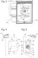
- Fig.3 shows a perspective view of an inner container 23 of a lower chamber 44 in a combination refrigerator.
- An inner container of an upper chamber is shown in fragmentary form.
- a bulge 25 is formed on a side wall 24 of the inner container 23; at the bottom of the bulge an opening 26 is cut into the outer wall through which parts of a connection point such as the connection point 5 of Fig.1 or 2 can be seen.
- electrical devices such as a temperature sensor or interior lighting can be accommodated in the recess 25.
- a channel 27 runs from the recess 25 to a rear wall 28 of the inner container.
- cables from electrical devices in the evaporator chamber such as a fan, an evaporator temperature sensor, a defrost heater, etc., run via the channel 27.
- Fig.4 shows the bottom of the recess in a view from the outside.
- the opening 26 is covered by a connection housing 29.
- the connection housing 29 comprises a main part 30, which is locked to the inner container 23 in a manner described in more detail below and on its side facing away from the inner container, adjacent to a rear wall 32, a Fig.4 dashed, elongated opening 31 and a cover 33 which closes the opening 31 and together with the main part defines a lateral cable outlet 34.
- the cable outlet 34 is in Fig.4 shown empty; in practice, before the cover 33 is mounted on the main part 30 in the position shown, a harness-side connector 8 is introduced into the main part 30 through the opening 31, and the cable outlet 34 is sealed with foam by a branch of the harness 1 extending from the connector 8 and a seal surrounding the branch in order to prevent foam from penetrating into the connection housing 29 or even the inner container 23 when a heat-insulating foam layer is applied to the outside of the inner container 23 in the usual manner.
- Fig.5 shows the connection housing 29 mounted in the opening 26 in a view from the inside.
- the adapter 2 plugged into the connector 8 projects diagonally through the opening 26.
- its upper and lower edges 36, 37 are hidden behind two webs 38 projecting upwards and downwards from the main part 30.
- the edges 36, 37 are exposed.
- connection housing 29 is mounted in the opening 26 by passing the webs 38 with their left end first through the wide section of the opening 26 from the outside and then sliding the main part 30 against the inner container 23 until the webs 38 have completely passed through the opening 26 and a locking projection 39 formed on the right end of the webs 38 locks into place on the right edge of the opening 26.
- the webs 38 can be inserted at their ends first into the opening 26 as shown in Fig. 6 shown, be provided with insertion aids 40, which extend the webs 38 similarly to the tips of skis and, after being installed in the opening 26, protrude obliquely from the inner container 23.
- Fig. 6 is also the in Fig. 5 Connectors 14 on the device side, which are still shown separately, are plugged onto the adapter 2.
- the assembly 41 consisting of adapter 2 and plug connectors 8, 14 is pivoted into the connection housing 29 so that, as in Fig. 7 shown, the adapter 2 is essentially one assumes a vertical orientation and the connector 14 also disappears completely in the connection housing 29 and only the (in Fig. 7 (not shown) cables extending from it to the electrical devices mounted in the inner container extend through the opening 26.
- the connector 14 can be provided with two lateral projections 42, and the connection housing 29 has two forks 43 which project from its rear wall 32 adjacent to its right and left edges towards the opening 26 and from which in Fig.5 and Fig.7 only the tip of a prong is visible at any one time.
- the distance between the forks 43 and the underside of the connection housing supporting the connector 8 is selected such that the projections 42 can only engage between the prongs of the forks 43 if the connectors 8, 14 and the adapter 2 are correctly plugged together.
- the distance between the prongs is selected such that they clamp a projection 42 inserted between them at least with friction; they can also be undercut to enable a positive engagement of the projection 42. Insertion bevels on the tips of the prongs make it easier to insert the projections 42.
Landscapes
- Engineering & Computer Science (AREA)
- Chemical & Material Sciences (AREA)
- Combustion & Propulsion (AREA)
- Physics & Mathematics (AREA)
- Mechanical Engineering (AREA)
- Thermal Sciences (AREA)
- General Engineering & Computer Science (AREA)
- Connector Housings Or Holding Contact Members (AREA)
- Coupling Device And Connection With Printed Circuit (AREA)
Claims (16)
- Appareil frigorifique avec plusieurs dispositifs électriques répartis dans une carcasse d'appareil et un faisceau de câbles (1) alimentant les dispositifs électriques, dans lequel au moins un premier point de raccordement (5) du faisceau de câbles (1) présente un connecteur côté faisceau de câbles (8) et les dispositifs électriques alimentés via le premier point de raccordement (5) sont reliés au connecteur côté faisceau de câbles (8) via un connecteur côté dispositifs (14) et un adaptateur (2, 3) assemblé avec les deux connecteurs (8, 14), caractérisé en ce que l'adaptateur (2, 3) présente un conducteur (18) qui relie l'un à l'autre au moins deux contacts du connecteur côté dispositifs.
- Appareil frigorifique selon la revendication 1, caractérisé en ce que les connecteurs sont des connecteurs de bord et l'adaptateur (2, 3) est un circuit imprimé, dont les bords portent des contacts sur lesquels les connecteurs de bord sont enfichés.
- Appareil frigorifique selon la revendication 2, caractérisé en ce que parmi les contacts de l'adaptateur (2, 3), au moins deux contacts (19, 20) sont reliés via un composant soudé sur le circuit imprimé.
- Appareil frigorifique selon l'une des revendications précédentes, caractérisé en ce que le conducteur (18) n'est pas relié au connecteur côté faisceau de câbles.
- Appareil frigorifique selon l'une des revendications 1 à 4, caractérisé en ce que le conducteur est relié au connecteur côté faisceau de câbles.
- Appareil frigorifique selon l'une des revendications précédentes, caractérisé en ce que l'adaptateur (2, 3) présente un conducteur (21, 22) qui relie au moins deux contacts du connecteur côté faisceau de câbles (8).
- Appareil frigorifique selon la revendication 6, caractérisé en ce que le faisceau de câbles présente une première ligne (9), qui s'étend d'un premier parmi les deux contacts du connecteur côté faisceau de câbles (8) vers un deuxième point de raccordement (4) et une deuxième ligne (9) qui s'étend du deuxième parmi les deux contacts vers un troisième point de raccordement (6).
- Appareil frigorifique selon l'une des revendications 1 à 7, caractérisé en ce que le connecteur côté faisceau de câbles (8) comprend respectivement un seul porte-contacts, auquel l'ensemble des contacts du connecteur sont fixés.
- Appareil frigorifique selon l'une des revendications 1 à 7, caractérisé en ce que les contacts du connecteur côté faisceau de câbles sont répartis sur plusieurs porte-contacts respectifs.
- Appareil frigorifique selon l'une des revendications précédentes, caractérisé en ce que la carcasse d'appareil est subdivisée en plusieurs chambres et en ce que les dispositifs électriques alimentés par le premier point de raccordement (5) sont logés dans une première (44) de ces chambres.
- Appareil frigorifique selon l'une des revendications précédentes, caractérisé en ce que le faisceau de câbles est encastré dans une couche de matériau isolant de la carcasse d'appareil.
- Appareil frigorifique selon l'une des revendications précédentes, caractérisé en ce que le premier point de raccordement (5) comprend une carcasse de raccordement (29) dans laquelle les connecteurs (8, 14) et le circuit imprimé (11) du point de contact (5) sont logés.
- Appareil frigorifique selon la revendication 10 et la revendication 12, caractérisé en ce que la carcasse de raccordement (29) du premier point de raccordement (5) est montée sur une paroi (24) de la première chambre (44).
- Appareil frigorifique selon la revendication 13, caractérisé en ce que la carcasse de raccordement (29) comble un orifice (26) de la paroi (24).
- Appareil frigorifique selon la revendication 13 ou 14, caractérisé en ce que la carcasse de raccordement (29) est insérable dans l'orifice (26) par déplacement dans un sens parallèle à la surface de la paroi (24) et présente deux âmes de bord (38) insérables à travers une section large de l'orifice (26) transversale au sens de déplacement et contiguës, à l'état monté sur la paroi, de chaque côté à une section étroite de l'orifice (26).
- Appareil frigorifique selon la revendication 15, caractérisé en ce que la carcasse de raccordement (29) est ouverte en direction de la chambre (44) et les connecteurs (8, 14) et l'adaptateur (2, 3) peuvent être pivotés entre une position dans laquelle ils sont accueillis dans la carcasse de raccordement (29) et une position dans laquelle au moins le connecteur côté dispositifs (14) fait saillie de la carcasse de raccordement (29) dans la chambre (44).
Applications Claiming Priority (2)
| Application Number | Priority Date | Filing Date | Title |
|---|---|---|---|
| DE102016224705.0A DE102016224705A1 (de) | 2016-12-12 | 2016-12-12 | Elektrogerät mit verteilten elektrischen Einrichtungen |
| PCT/EP2017/080399 WO2018108491A1 (fr) | 2016-12-12 | 2017-11-24 | Appareil électrique comprenant des dispositifs électriques distribués |
Publications (2)
| Publication Number | Publication Date |
|---|---|
| EP3551949A1 EP3551949A1 (fr) | 2019-10-16 |
| EP3551949B1 true EP3551949B1 (fr) | 2024-04-03 |
Family
ID=60515372
Family Applications (1)
| Application Number | Title | Priority Date | Filing Date |
|---|---|---|---|
| EP17807813.5A Active EP3551949B1 (fr) | 2016-12-12 | 2017-11-24 | Réfrigérateur ayant des dispositifs électriques étalés |
Country Status (6)
| Country | Link |
|---|---|
| US (2) | US11555649B2 (fr) |
| EP (1) | EP3551949B1 (fr) |
| CN (1) | CN110050166B (fr) |
| DE (1) | DE102016224705A1 (fr) |
| PL (1) | PL3551949T3 (fr) |
| WO (1) | WO2018108491A1 (fr) |
Families Citing this family (4)
| Publication number | Priority date | Publication date | Assignee | Title |
|---|---|---|---|---|
| DE102016224705A1 (de) * | 2016-12-12 | 2018-06-14 | BSH Hausgeräte GmbH | Elektrogerät mit verteilten elektrischen Einrichtungen |
| DE102017127031A1 (de) * | 2017-11-16 | 2019-05-16 | Liebherr-Hausgeräte Ochsenhausen GmbH | Kühl- und/oder Gerfriergerät |
| CN113068301B (zh) * | 2021-03-17 | 2022-10-28 | 深圳乔合里科技股份有限公司 | 内置pcb板的整车线束及其控制电路 |
| DE102022128842A1 (de) * | 2022-09-05 | 2024-03-07 | Liebherr-Hausgeräte Marica EOOD | Kühl- und/oder Gefriergerät |
Family Cites Families (48)
| Publication number | Priority date | Publication date | Assignee | Title |
|---|---|---|---|---|
| US2441643A (en) * | 1946-05-13 | 1948-05-18 | Mickler Stanislaus Albert | Protective electrical outlet receptacle |
| US3179852A (en) * | 1961-11-24 | 1965-04-20 | Gen Motors Corp | Refrigeration relay box and condenser assembly |
| US3281558A (en) * | 1964-03-16 | 1966-10-25 | Mcdonnell Aircraft Corp | Multiple circuit protector device |
| US3509356A (en) * | 1967-12-15 | 1970-04-28 | Peebles David M | Selective circuit connector |
| FR2111985B1 (fr) | 1972-02-23 | 1974-07-05 | Emerjy | |
| US4006959A (en) * | 1974-11-04 | 1977-02-08 | Amp Incorporated | Intrinsic certification assembly technique for wiring components into an electrical apparatus |
| US4218110A (en) * | 1979-04-04 | 1980-08-19 | The United States Of America As Represented By The Secretary Of The Navy | Connector-to-connector adaptor |
| JPS5940653B2 (ja) * | 1979-06-04 | 1984-10-02 | 日産自動車株式会社 | □/車両用計器盤の結線構造□/ |
| JPS6089669A (ja) | 1983-10-19 | 1985-05-20 | 三洋電機株式会社 | 冷蔵庫の断熱箱体製造方法 |
| US4543800A (en) * | 1984-02-16 | 1985-10-01 | White Consolidated Industries, Inc. | Refrigerator door hinge |
| FR2593085B1 (fr) * | 1986-01-23 | 1990-10-26 | Hauville Francois | Table de laboratoire. |
| EP0265698B1 (fr) * | 1986-09-30 | 1994-03-30 | Fauzi Bekhiet | Dispositif de connexion pour la connexion électrique des branchements d'appareils électriques |
| US4950169A (en) * | 1989-03-13 | 1990-08-21 | Pc Industries, Inc. | Universal cable connector for electronic devices |
| US4986762A (en) * | 1989-08-15 | 1991-01-22 | Minnesota Mining And Manufacturing Company | Termination module for use in an array of modules |
| US5348485A (en) * | 1993-04-12 | 1994-09-20 | Electronic Retailing Systems Int'l Inc. | Electronic price display system with vertical rail |
| JP3006398B2 (ja) * | 1993-05-05 | 2000-02-07 | インターナショナル・ビジネス・マシーンズ・コーポレイション | ケーブル・アセンブリ |
| US5626479A (en) * | 1993-07-16 | 1997-05-06 | Hughes; Michael T. | Unified connector interface adapter |
| KR0130883Y1 (ko) * | 1994-02-02 | 1998-12-15 | 김광호 | 컴퓨터의 하드 디스크 드라이버 착탈장치 |
| JPH08205265A (ja) | 1994-11-25 | 1996-08-09 | Sharp Corp | 機器内配線コントロールシステム |
| JP3404224B2 (ja) | 1996-08-07 | 2003-05-06 | 松下冷機株式会社 | 冷蔵庫の温度調節装置 |
| US6028267A (en) * | 1997-04-15 | 2000-02-22 | Byrne; Norman R. | Rotatable power center system |
| US5984716A (en) * | 1997-06-09 | 1999-11-16 | Progressive Components International Corporation | Electrical connection system for mold components and a plastic injection molding press |
| US6159041A (en) * | 1999-03-01 | 2000-12-12 | The Whitaker Corporation | Electrical connector assembly for panel mounting |
| US6397609B1 (en) * | 1999-08-20 | 2002-06-04 | Denso Corporation | Vehicle air-conditioning system with arrangement of electrical member |
| JP3855143B2 (ja) | 1999-10-14 | 2006-12-06 | 三菱電機株式会社 | 冷蔵庫 |
| IT250075Y1 (it) | 2000-06-20 | 2003-07-07 | Whirlpool Co | Centralina raggruppatrice di componenti elettronici per frigoriferi congelatori e simili apparecchi |
| JP2003065658A (ja) | 2001-08-27 | 2003-03-05 | Toshiba Corp | 冷蔵庫のプリント回路板接続構造 |
| US6500025B1 (en) * | 2002-03-13 | 2002-12-31 | Honeywell International Inc. | Universal cable assembly for both parallel and serial component connections |
| DE10221898B4 (de) | 2002-05-16 | 2005-01-27 | BSH Bosch und Siemens Hausgeräte GmbH | Kältegerät mit beheizbarem Innenraum |
| US6737582B2 (en) * | 2002-08-02 | 2004-05-18 | Seiko Epson Corporation | Power connector |
| US7404298B2 (en) * | 2003-03-10 | 2008-07-29 | Lg Electronics Inc. | Refrigerator |
| US20040248462A1 (en) * | 2003-06-06 | 2004-12-09 | Dyer Jonathan T. | Modular wiring harness and power cord for vending machines |
| US6933452B2 (en) * | 2003-08-27 | 2005-08-23 | Edward Liu | Terminal connection device for speaker |
| DE102004019349A1 (de) | 2003-12-23 | 2005-07-28 | BSH Bosch und Siemens Hausgeräte GmbH | Anschlusseinrichtung zum Herstellen einer elektrischen Verbindung zwischen einem Netzkabel und einem Kabelbaum |
| DK1813002T3 (da) * | 2004-11-19 | 2011-06-14 | Uponor Innovations Ab | Fremgangsmåde og apparat til kontrol af et netværk i HVAC og andre anvendelser |
| US7410361B2 (en) * | 2006-10-13 | 2008-08-12 | Sound Sources Technology | Terminal for selectively coupling loads in parallel or in series |
| KR100758990B1 (ko) * | 2006-11-13 | 2007-09-17 | 삼성광주전자 주식회사 | 냉장고 |
| US8299656B2 (en) * | 2008-03-12 | 2012-10-30 | Whirlpool Corporation | Feature module connection system |
| US8360802B2 (en) * | 2009-11-12 | 2013-01-29 | Whirlpool Corporation | Adjustable connector system for connection to a modular appliance |
| US20080164758A1 (en) | 2007-01-04 | 2008-07-10 | Mccoy Richard A | Electrical accessory charging compartment for a cabinet and retrofit components therefor |
| JP4934446B2 (ja) * | 2007-01-31 | 2012-05-16 | 三洋電機株式会社 | 冷却貯蔵庫 |
| WO2009114697A1 (fr) * | 2008-03-12 | 2009-09-17 | Whirlpool Corporation | Réfrigérateur avec module recevant des conduits |
| JP5320243B2 (ja) | 2009-09-29 | 2013-10-23 | 矢崎総業株式会社 | 基板用コネクタの実装構造 |
| US8860328B2 (en) * | 2011-12-29 | 2014-10-14 | National Christmas Products | Method and apparatus for controlling a multi-colored LED light string |
| DE102013209747A1 (de) | 2013-05-27 | 2014-11-27 | BSH Bosch und Siemens Hausgeräte GmbH | Kältegerät mit einem Elektronikgehäuse |
| KR101944361B1 (ko) | 2014-01-06 | 2019-02-01 | 삼성전자주식회사 | 커넥터 및 이를 포함하는 냉장고 |
| DE102014118597A1 (de) | 2014-12-15 | 2016-06-16 | Dr. Hahn Gmbh & Co. Kg | Verfahren und Vorrichtung zur Übertragung von elektrischer Leistung und/oder von Signalen zwischen einer Wand und einem gegenüber dieser Wand schwenkbaren Flügel |
| DE102016224705A1 (de) * | 2016-12-12 | 2018-06-14 | BSH Hausgeräte GmbH | Elektrogerät mit verteilten elektrischen Einrichtungen |
-
2016
- 2016-12-12 DE DE102016224705.0A patent/DE102016224705A1/de active Pending
-
2017
- 2017-11-24 EP EP17807813.5A patent/EP3551949B1/fr active Active
- 2017-11-24 US US16/468,915 patent/US11555649B2/en active Active
- 2017-11-24 PL PL17807813.5T patent/PL3551949T3/pl unknown
- 2017-11-24 WO PCT/EP2017/080399 patent/WO2018108491A1/fr not_active Ceased
- 2017-11-24 CN CN201780075696.6A patent/CN110050166B/zh active Active
-
2022
- 2022-10-27 US US17/974,739 patent/US20230048164A1/en not_active Abandoned
Also Published As
| Publication number | Publication date |
|---|---|
| US20230048164A1 (en) | 2023-02-16 |
| EP3551949A1 (fr) | 2019-10-16 |
| US20200080770A1 (en) | 2020-03-12 |
| US11555649B2 (en) | 2023-01-17 |
| WO2018108491A1 (fr) | 2018-06-21 |
| DE102016224705A1 (de) | 2018-06-14 |
| PL3551949T3 (pl) | 2024-07-22 |
| CN110050166A (zh) | 2019-07-23 |
| CN110050166B (zh) | 2023-10-13 |
Similar Documents
| Publication | Publication Date | Title |
|---|---|---|
| DE69219791T2 (de) | Modulare auswechselbare Energieverteilungsvorrichtung | |
| DE3004372C2 (fr) | ||
| DE69211833T2 (de) | Installationseinrichtung für Netzanschluss | |
| EP3551949B1 (fr) | Réfrigérateur ayant des dispositifs électriques étalés | |
| DE69503112T2 (de) | Ein Bauelement für eine Schaltung und eine Anschlussdose | |
| DE19612575C2 (de) | Vorrichtung zur lösbaren Befestigung von Geräten und zu deren elektrischem Anschließen | |
| DE102009003509A1 (de) | Präsentationssystem mit Trägerprofilschiene | |
| EP3701606B1 (fr) | Système de support de câbles, élément de rail conducteur, procédé de fabrication d'un élément de rail conducteur et procédé de fabrication d'un système de rails conducteurs | |
| EP2946644A1 (fr) | Ensemble doté d'un module et d'un dispositif électronique | |
| DE3912210A1 (de) | Elektrisches verteilergehaeuse und verfahren zu dessen herstellung | |
| DE102017219078A1 (de) | Abzweigstruktur und Drahtkabelbaum | |
| EP0613210A2 (fr) | Installation pour un actionneur | |
| DE212016000059U1 (de) | An einer Schiene anbringbares Steuersystem mit verbesserter Anbringung | |
| DE29606772U1 (de) | Vorrichtung zum elektrischen Anschluß von Kühlgerätebauteilen | |
| WO2011054743A2 (fr) | Agencement de montage pour appareils électriques | |
| DE19714868C2 (de) | Busfähige elektrische Koppeleinheit | |
| DE4409183C2 (de) | Einrichtung zum elektrischen Anschluß einer zentralen Steuerschaltungsplatte | |
| DE29505272U1 (de) | Sensor-Aktor-Verteiler | |
| DE102012012087B4 (de) | Elektrischer Steckverbinder | |
| EP4309248A1 (fr) | Système de distribution pour un réseau électrique de bord et ligne d'alimentation pour un tel système de distribution | |
| DE8115274U1 (de) | Vorrichtung zum Herstellen einer elektrischen Steckverbindung | |
| DE19741221B4 (de) | Sicherungskasten | |
| EP2034568B1 (fr) | Boîte de raccordement pour technologie des données | |
| DE69508213T2 (de) | Zentralisierter Verbindungsblock für eine Heizungs- und/oder Klimaanlage eines Kraftfahrzeuges | |
| DE102014105725A1 (de) | Elektrisches Gerät und Leiteranschlussklemme sowie Sockelteil hierzu |
Legal Events
| Date | Code | Title | Description |
|---|---|---|---|
| STAA | Information on the status of an ep patent application or granted ep patent |
Free format text: STATUS: UNKNOWN |
|
| STAA | Information on the status of an ep patent application or granted ep patent |
Free format text: STATUS: THE INTERNATIONAL PUBLICATION HAS BEEN MADE |
|
| PUAI | Public reference made under article 153(3) epc to a published international application that has entered the european phase |
Free format text: ORIGINAL CODE: 0009012 |
|
| STAA | Information on the status of an ep patent application or granted ep patent |
Free format text: STATUS: REQUEST FOR EXAMINATION WAS MADE |
|
| 17P | Request for examination filed |
Effective date: 20190712 |
|
| AK | Designated contracting states |
Kind code of ref document: A1 Designated state(s): AL AT BE BG CH CY CZ DE DK EE ES FI FR GB GR HR HU IE IS IT LI LT LU LV MC MK MT NL NO PL PT RO RS SE SI SK SM TR |
|
| AX | Request for extension of the european patent |
Extension state: BA ME |
|
| RIN1 | Information on inventor provided before grant (corrected) |
Inventor name: XIAO, XIANG Inventor name: WIEDENMANN, MATTHIAS Inventor name: KRAUSS, HARALD Inventor name: WERTS, THOMAS |
|
| DAV | Request for validation of the european patent (deleted) | ||
| DAX | Request for extension of the european patent (deleted) | ||
| STAA | Information on the status of an ep patent application or granted ep patent |
Free format text: STATUS: EXAMINATION IS IN PROGRESS |
|
| 17Q | First examination report despatched |
Effective date: 20220228 |
|
| GRAP | Despatch of communication of intention to grant a patent |
Free format text: ORIGINAL CODE: EPIDOSNIGR1 |
|
| STAA | Information on the status of an ep patent application or granted ep patent |
Free format text: STATUS: GRANT OF PATENT IS INTENDED |
|
| INTG | Intention to grant announced |
Effective date: 20230929 |
|
| GRAJ | Information related to disapproval of communication of intention to grant by the applicant or resumption of examination proceedings by the epo deleted |
Free format text: ORIGINAL CODE: EPIDOSDIGR1 |
|
| STAA | Information on the status of an ep patent application or granted ep patent |
Free format text: STATUS: EXAMINATION IS IN PROGRESS |
|
| GRAP | Despatch of communication of intention to grant a patent |
Free format text: ORIGINAL CODE: EPIDOSNIGR1 |
|
| STAA | Information on the status of an ep patent application or granted ep patent |
Free format text: STATUS: GRANT OF PATENT IS INTENDED |
|
| INTC | Intention to grant announced (deleted) | ||
| GRAS | Grant fee paid |
Free format text: ORIGINAL CODE: EPIDOSNIGR3 |
|
| GRAA | (expected) grant |
Free format text: ORIGINAL CODE: 0009210 |
|
| STAA | Information on the status of an ep patent application or granted ep patent |
Free format text: STATUS: THE PATENT HAS BEEN GRANTED |
|
| INTG | Intention to grant announced |
Effective date: 20240207 |
|
| AK | Designated contracting states |
Kind code of ref document: B1 Designated state(s): AL AT BE BG CH CY CZ DE DK EE ES FI FR GB GR HR HU IE IS IT LI LT LU LV MC MK MT NL NO PL PT RO RS SE SI SK SM TR |
|
| REG | Reference to a national code |
Ref country code: GB Ref legal event code: FG4D Free format text: NOT ENGLISH |
|
| REG | Reference to a national code |
Ref country code: CH Ref legal event code: EP |
|
| REG | Reference to a national code |
Ref country code: IE Ref legal event code: FG4D Free format text: LANGUAGE OF EP DOCUMENT: GERMAN |
|
| REG | Reference to a national code |
Ref country code: DE Ref legal event code: R096 Ref document number: 502017015997 Country of ref document: DE |
|
| REG | Reference to a national code |
Ref country code: LT Ref legal event code: MG9D |
|
| REG | Reference to a national code |
Ref country code: NL Ref legal event code: MP Effective date: 20240403 |
|
| PG25 | Lapsed in a contracting state [announced via postgrant information from national office to epo] |
Ref country code: NL Free format text: LAPSE BECAUSE OF FAILURE TO SUBMIT A TRANSLATION OF THE DESCRIPTION OR TO PAY THE FEE WITHIN THE PRESCRIBED TIME-LIMIT Effective date: 20240403 |
|
| PG25 | Lapsed in a contracting state [announced via postgrant information from national office to epo] |
Ref country code: NL Free format text: LAPSE BECAUSE OF FAILURE TO SUBMIT A TRANSLATION OF THE DESCRIPTION OR TO PAY THE FEE WITHIN THE PRESCRIBED TIME-LIMIT Effective date: 20240403 |
|
| PG25 | Lapsed in a contracting state [announced via postgrant information from national office to epo] |
Ref country code: IS Free format text: LAPSE BECAUSE OF FAILURE TO SUBMIT A TRANSLATION OF THE DESCRIPTION OR TO PAY THE FEE WITHIN THE PRESCRIBED TIME-LIMIT Effective date: 20240803 |
|
| PG25 | Lapsed in a contracting state [announced via postgrant information from national office to epo] |
Ref country code: BG Free format text: LAPSE BECAUSE OF FAILURE TO SUBMIT A TRANSLATION OF THE DESCRIPTION OR TO PAY THE FEE WITHIN THE PRESCRIBED TIME-LIMIT Effective date: 20240403 |
|
| PG25 | Lapsed in a contracting state [announced via postgrant information from national office to epo] |
Ref country code: FI Free format text: LAPSE BECAUSE OF FAILURE TO SUBMIT A TRANSLATION OF THE DESCRIPTION OR TO PAY THE FEE WITHIN THE PRESCRIBED TIME-LIMIT Effective date: 20240403 Ref country code: HR Free format text: LAPSE BECAUSE OF FAILURE TO SUBMIT A TRANSLATION OF THE DESCRIPTION OR TO PAY THE FEE WITHIN THE PRESCRIBED TIME-LIMIT Effective date: 20240403 |
|
| PG25 | Lapsed in a contracting state [announced via postgrant information from national office to epo] |
Ref country code: GR Free format text: LAPSE BECAUSE OF FAILURE TO SUBMIT A TRANSLATION OF THE DESCRIPTION OR TO PAY THE FEE WITHIN THE PRESCRIBED TIME-LIMIT Effective date: 20240704 |
|
| PG25 | Lapsed in a contracting state [announced via postgrant information from national office to epo] |
Ref country code: PT Free format text: LAPSE BECAUSE OF FAILURE TO SUBMIT A TRANSLATION OF THE DESCRIPTION OR TO PAY THE FEE WITHIN THE PRESCRIBED TIME-LIMIT Effective date: 20240805 |
|
| PG25 | Lapsed in a contracting state [announced via postgrant information from national office to epo] |
Ref country code: ES Free format text: LAPSE BECAUSE OF FAILURE TO SUBMIT A TRANSLATION OF THE DESCRIPTION OR TO PAY THE FEE WITHIN THE PRESCRIBED TIME-LIMIT Effective date: 20240403 |
|
| PG25 | Lapsed in a contracting state [announced via postgrant information from national office to epo] |
Ref country code: CZ Free format text: LAPSE BECAUSE OF FAILURE TO SUBMIT A TRANSLATION OF THE DESCRIPTION OR TO PAY THE FEE WITHIN THE PRESCRIBED TIME-LIMIT Effective date: 20240403 |
|
| PG25 | Lapsed in a contracting state [announced via postgrant information from national office to epo] |
Ref country code: LV Free format text: LAPSE BECAUSE OF FAILURE TO SUBMIT A TRANSLATION OF THE DESCRIPTION OR TO PAY THE FEE WITHIN THE PRESCRIBED TIME-LIMIT Effective date: 20240403 |
|
| PG25 | Lapsed in a contracting state [announced via postgrant information from national office to epo] |
Ref country code: PT Free format text: LAPSE BECAUSE OF FAILURE TO SUBMIT A TRANSLATION OF THE DESCRIPTION OR TO PAY THE FEE WITHIN THE PRESCRIBED TIME-LIMIT Effective date: 20240805 Ref country code: NO Free format text: LAPSE BECAUSE OF FAILURE TO SUBMIT A TRANSLATION OF THE DESCRIPTION OR TO PAY THE FEE WITHIN THE PRESCRIBED TIME-LIMIT Effective date: 20240703 Ref country code: LV Free format text: LAPSE BECAUSE OF FAILURE TO SUBMIT A TRANSLATION OF THE DESCRIPTION OR TO PAY THE FEE WITHIN THE PRESCRIBED TIME-LIMIT Effective date: 20240403 Ref country code: IS Free format text: LAPSE BECAUSE OF FAILURE TO SUBMIT A TRANSLATION OF THE DESCRIPTION OR TO PAY THE FEE WITHIN THE PRESCRIBED TIME-LIMIT Effective date: 20240803 Ref country code: HR Free format text: LAPSE BECAUSE OF FAILURE TO SUBMIT A TRANSLATION OF THE DESCRIPTION OR TO PAY THE FEE WITHIN THE PRESCRIBED TIME-LIMIT Effective date: 20240403 Ref country code: GR Free format text: LAPSE BECAUSE OF FAILURE TO SUBMIT A TRANSLATION OF THE DESCRIPTION OR TO PAY THE FEE WITHIN THE PRESCRIBED TIME-LIMIT Effective date: 20240704 Ref country code: FI Free format text: LAPSE BECAUSE OF FAILURE TO SUBMIT A TRANSLATION OF THE DESCRIPTION OR TO PAY THE FEE WITHIN THE PRESCRIBED TIME-LIMIT Effective date: 20240403 Ref country code: ES Free format text: LAPSE BECAUSE OF FAILURE TO SUBMIT A TRANSLATION OF THE DESCRIPTION OR TO PAY THE FEE WITHIN THE PRESCRIBED TIME-LIMIT Effective date: 20240403 Ref country code: CZ Free format text: LAPSE BECAUSE OF FAILURE TO SUBMIT A TRANSLATION OF THE DESCRIPTION OR TO PAY THE FEE WITHIN THE PRESCRIBED TIME-LIMIT Effective date: 20240403 Ref country code: BG Free format text: LAPSE BECAUSE OF FAILURE TO SUBMIT A TRANSLATION OF THE DESCRIPTION OR TO PAY THE FEE WITHIN THE PRESCRIBED TIME-LIMIT Effective date: 20240403 Ref country code: RS Free format text: LAPSE BECAUSE OF FAILURE TO SUBMIT A TRANSLATION OF THE DESCRIPTION OR TO PAY THE FEE WITHIN THE PRESCRIBED TIME-LIMIT Effective date: 20240703 |
|
| REG | Reference to a national code |
Ref country code: DE Ref legal event code: R097 Ref document number: 502017015997 Country of ref document: DE |
|
| PG25 | Lapsed in a contracting state [announced via postgrant information from national office to epo] |
Ref country code: DK Free format text: LAPSE BECAUSE OF FAILURE TO SUBMIT A TRANSLATION OF THE DESCRIPTION OR TO PAY THE FEE WITHIN THE PRESCRIBED TIME-LIMIT Effective date: 20240403 |
|
| PG25 | Lapsed in a contracting state [announced via postgrant information from national office to epo] |
Ref country code: EE Free format text: LAPSE BECAUSE OF FAILURE TO SUBMIT A TRANSLATION OF THE DESCRIPTION OR TO PAY THE FEE WITHIN THE PRESCRIBED TIME-LIMIT Effective date: 20240403 |
|
| PG25 | Lapsed in a contracting state [announced via postgrant information from national office to epo] |
Ref country code: RO Free format text: LAPSE BECAUSE OF FAILURE TO SUBMIT A TRANSLATION OF THE DESCRIPTION OR TO PAY THE FEE WITHIN THE PRESCRIBED TIME-LIMIT Effective date: 20240403 Ref country code: SK Free format text: LAPSE BECAUSE OF FAILURE TO SUBMIT A TRANSLATION OF THE DESCRIPTION OR TO PAY THE FEE WITHIN THE PRESCRIBED TIME-LIMIT Effective date: 20240403 |
|
| PG25 | Lapsed in a contracting state [announced via postgrant information from national office to epo] |
Ref country code: SM Free format text: LAPSE BECAUSE OF FAILURE TO SUBMIT A TRANSLATION OF THE DESCRIPTION OR TO PAY THE FEE WITHIN THE PRESCRIBED TIME-LIMIT Effective date: 20240403 |
|
| PG25 | Lapsed in a contracting state [announced via postgrant information from national office to epo] |
Ref country code: SM Free format text: LAPSE BECAUSE OF FAILURE TO SUBMIT A TRANSLATION OF THE DESCRIPTION OR TO PAY THE FEE WITHIN THE PRESCRIBED TIME-LIMIT Effective date: 20240403 Ref country code: SK Free format text: LAPSE BECAUSE OF FAILURE TO SUBMIT A TRANSLATION OF THE DESCRIPTION OR TO PAY THE FEE WITHIN THE PRESCRIBED TIME-LIMIT Effective date: 20240403 Ref country code: RO Free format text: LAPSE BECAUSE OF FAILURE TO SUBMIT A TRANSLATION OF THE DESCRIPTION OR TO PAY THE FEE WITHIN THE PRESCRIBED TIME-LIMIT Effective date: 20240403 Ref country code: EE Free format text: LAPSE BECAUSE OF FAILURE TO SUBMIT A TRANSLATION OF THE DESCRIPTION OR TO PAY THE FEE WITHIN THE PRESCRIBED TIME-LIMIT Effective date: 20240403 Ref country code: DK Free format text: LAPSE BECAUSE OF FAILURE TO SUBMIT A TRANSLATION OF THE DESCRIPTION OR TO PAY THE FEE WITHIN THE PRESCRIBED TIME-LIMIT Effective date: 20240403 |
|
| PLBE | No opposition filed within time limit |
Free format text: ORIGINAL CODE: 0009261 |
|
| STAA | Information on the status of an ep patent application or granted ep patent |
Free format text: STATUS: NO OPPOSITION FILED WITHIN TIME LIMIT |
|
| 26N | No opposition filed |
Effective date: 20250106 |
|
| PG25 | Lapsed in a contracting state [announced via postgrant information from national office to epo] |
Ref country code: SI Free format text: LAPSE BECAUSE OF FAILURE TO SUBMIT A TRANSLATION OF THE DESCRIPTION OR TO PAY THE FEE WITHIN THE PRESCRIBED TIME-LIMIT Effective date: 20240403 |
|
| REG | Reference to a national code |
Ref country code: CH Ref legal event code: PL |
|
| PG25 | Lapsed in a contracting state [announced via postgrant information from national office to epo] |
Ref country code: MC Free format text: LAPSE BECAUSE OF FAILURE TO SUBMIT A TRANSLATION OF THE DESCRIPTION OR TO PAY THE FEE WITHIN THE PRESCRIBED TIME-LIMIT Effective date: 20240403 |
|
| PG25 | Lapsed in a contracting state [announced via postgrant information from national office to epo] |
Ref country code: LU Free format text: LAPSE BECAUSE OF NON-PAYMENT OF DUE FEES Effective date: 20241124 |
|
| REG | Reference to a national code |
Ref country code: CH Ref legal event code: PL |
|
| GBPC | Gb: european patent ceased through non-payment of renewal fee |
Effective date: 20241124 |
|
| PG25 | Lapsed in a contracting state [announced via postgrant information from national office to epo] |
Ref country code: CH Free format text: LAPSE BECAUSE OF NON-PAYMENT OF DUE FEES Effective date: 20241130 |
|
| REG | Reference to a national code |
Ref country code: BE Ref legal event code: MM Effective date: 20241130 |
|
| PG25 | Lapsed in a contracting state [announced via postgrant information from national office to epo] |
Ref country code: SE Free format text: LAPSE BECAUSE OF FAILURE TO SUBMIT A TRANSLATION OF THE DESCRIPTION OR TO PAY THE FEE WITHIN THE PRESCRIBED TIME-LIMIT Effective date: 20240403 |
|
| PG25 | Lapsed in a contracting state [announced via postgrant information from national office to epo] |
Ref country code: BE Free format text: LAPSE BECAUSE OF NON-PAYMENT OF DUE FEES Effective date: 20241130 Ref country code: GB Free format text: LAPSE BECAUSE OF NON-PAYMENT OF DUE FEES Effective date: 20241124 |
|
| PG25 | Lapsed in a contracting state [announced via postgrant information from national office to epo] |
Ref country code: FR Free format text: LAPSE BECAUSE OF NON-PAYMENT OF DUE FEES Effective date: 20241130 |
|
| PG25 | Lapsed in a contracting state [announced via postgrant information from national office to epo] |
Ref country code: IE Free format text: LAPSE BECAUSE OF NON-PAYMENT OF DUE FEES Effective date: 20241124 |
|
| PGFP | Annual fee paid to national office [announced via postgrant information from national office to epo] |
Ref country code: DE Payment date: 20251130 Year of fee payment: 9 |
|
| PG25 | Lapsed in a contracting state [announced via postgrant information from national office to epo] |
Ref country code: AT Free format text: LAPSE BECAUSE OF NON-PAYMENT OF DUE FEES Effective date: 20241124 |
|
| REG | Reference to a national code |
Ref country code: AT Ref legal event code: MM01 Ref document number: 1672749 Country of ref document: AT Kind code of ref document: T Effective date: 20241124 |
|
| PGFP | Annual fee paid to national office [announced via postgrant information from national office to epo] |
Ref country code: TR Payment date: 20251118 Year of fee payment: 9 |
|
| PGFP | Annual fee paid to national office [announced via postgrant information from national office to epo] |
Ref country code: PL Payment date: 20251113 Year of fee payment: 9 |
|
| PG25 | Lapsed in a contracting state [announced via postgrant information from national office to epo] |
Ref country code: IT Free format text: LAPSE BECAUSE OF FAILURE TO SUBMIT A TRANSLATION OF THE DESCRIPTION OR TO PAY THE FEE WITHIN THE PRESCRIBED TIME-LIMIT Effective date: 20240403 |
|
| PG25 | Lapsed in a contracting state [announced via postgrant information from national office to epo] |
Ref country code: HU Free format text: LAPSE BECAUSE OF FAILURE TO SUBMIT A TRANSLATION OF THE DESCRIPTION OR TO PAY THE FEE WITHIN THE PRESCRIBED TIME-LIMIT; INVALID AB INITIO Effective date: 20171124 |
|
| PG25 | Lapsed in a contracting state [announced via postgrant information from national office to epo] |
Ref country code: CY Free format text: LAPSE BECAUSE OF FAILURE TO SUBMIT A TRANSLATION OF THE DESCRIPTION OR TO PAY THE FEE WITHIN THE PRESCRIBED TIME-LIMIT; INVALID AB INITIO Effective date: 20171124 |