EP3551939B1 - Appareil de cuisson ménager - Google Patents
Appareil de cuisson ménager Download PDFInfo
- Publication number
- EP3551939B1 EP3551939B1 EP17816503.1A EP17816503A EP3551939B1 EP 3551939 B1 EP3551939 B1 EP 3551939B1 EP 17816503 A EP17816503 A EP 17816503A EP 3551939 B1 EP3551939 B1 EP 3551939B1
- Authority
- EP
- European Patent Office
- Prior art keywords
- door
- sealing device
- pane
- door profile
- cooking appliance
- Prior art date
- Legal status (The legal status is an assumption and is not a legal conclusion. Google has not performed a legal analysis and makes no representation as to the accuracy of the status listed.)
- Active
Links
Images


Classifications
-
- F—MECHANICAL ENGINEERING; LIGHTING; HEATING; WEAPONS; BLASTING
- F24—HEATING; RANGES; VENTILATING
- F24C—DOMESTIC STOVES OR RANGES ; DETAILS OF DOMESTIC STOVES OR RANGES, OF GENERAL APPLICATION
- F24C15/00—Details
- F24C15/02—Doors specially adapted for stoves or ranges
- F24C15/04—Doors specially adapted for stoves or ranges with transparent panels
-
- F—MECHANICAL ENGINEERING; LIGHTING; HEATING; WEAPONS; BLASTING
- F24—HEATING; RANGES; VENTILATING
- F24C—DOMESTIC STOVES OR RANGES ; DETAILS OF DOMESTIC STOVES OR RANGES, OF GENERAL APPLICATION
- F24C15/00—Details
- F24C15/02—Doors specially adapted for stoves or ranges
- F24C15/021—Doors specially adapted for stoves or ranges sealings for doors or transparent panel
Definitions
- the present invention relates to a domestic cooking appliance.
- a domestic cooking appliance in particular an oven, can have a heatable cooking space.
- the cooking space can be locked with the help of a door.
- the door can have several panes which are arranged parallel to one another and spaced apart from one another and which are positioned relative to one another with the aid of door profiles. Sealing elements can be provided between the panes.
- the DE 103 14 214 A1 shows a furnace door for closing a furnace muffle with a multi-pane arrangement, consisting of at least an inner pane, an intermediate pane and an outer pane, with an air inlet opening in the lower door area and an air outlet opening in the upper door area, which are connected to the spaces between the panes of the oven door .
- a sealing element can be provided in the first intermediate space between the inner pane and the intermediate pane, which extends transversely to the panes in order to prevent an air flow from the air inlet opening to the air outlet opening via the first intermediate space.
- the DE 10 2011 088 082 A1 describes a door for a domestic cooking appliance with a first pane and a second pane, which is arranged at a distance from the first pane, and at least one sealing element arranged between the panes, the sealing element being an elongated component which is open in cross section and with a non-linear cross-sectional contour is formed, wherein the sealing element is formed reversibly deformable in at least one direction in the cross-sectional plane.
- the WO 2015/165499 A1 shows a door for an oven.
- the door includes a rear glass panel and a frame assembly having a first recess that releasably holds a lower end of the rear glass panel.
- the frame assembly includes a removable cover member with a snap-on portion for attaching / detaching the same and a flange for hiding and holding an upper end of the rear glass immovable.
- the EP 1 867 927 A2 describes a door for closing a loading opening of a cooking chamber of a cooking oven.
- the door comprises an outer pane, at least one inner pane, at least one holding element for holding the at least one inner pane, at least one cover element for covering the holding element, the at least one holding element and at least one cover element being produced separately and then connected to one another to form an assembly, with between the at least one cover element and the at least one holding element an air duct is formed, and wherein the assembly is the upper border of the door and / or is arranged in the upper region of the door.
- a domestic cooking appliance with a cooking space and a door for closing the cooking space comprises a first pane, a second pane arranged at a distance from the first pane, a first door profile, a second door profile arranged at a distance from the first door profile and a sealing device which is arranged in a gap provided between the first pane and the second pane , in order to seal the gap, the sealing device being attached to the first door profile and to the second door profile, the sealing device being hooked into the first door profile and the second door profile under prestress in such a way that the sealing device is elastically stretched when the same is installed Expansion is always maintained even after the assembly of the sealing device.
- the sealing device is fastened directly or directly to the door profiles, there is no need to fasten the sealing device directly to one of the panes. This enables simplified assembly and disassembly. This enables both a simplified production of the domestic cooking appliance and a simplified cleaning by a customer, since the sealing device can be easily dismantled. Furthermore, the fact that the sealing device is not directly on one of the Is attached prevents one or both of the discs from being damaged.
- the door preferably comprises more than two panes.
- the door can comprise four panes.
- the panes can for example be made of a glass material and be transparent at least in sections.
- the door can comprise the first pane, the second pane spaced apart from and parallel to the first pane, a third pane spaced apart from and parallel to the second pane, and a fourth pane arranged parallel to and spaced apart from the third pane.
- the fourth pane can be referred to as the outer pane or front pane.
- the first pane can be referred to as the inner pane.
- the second and third disks can each be referred to as an intermediate disk.
- a gap is provided between each of the disks.
- a first gap, in which the sealing device is arranged is provided between the first disk and the second disk.
- a second gap is provided between the second disk and the third disk and a third gap is provided between the third disk and the fourth disk.
- the door profiles are preferably attached to an inside of the fourth pane, for example glued to it.
- the door profiles can for example be made of a plastic material or a metal material.
- the panes can be positioned relative to one another.
- the panes are at least partially received in receiving sections of the door profiles.
- the panes can be positioned relative to one another at defined distances.
- the door profiles are arranged at least in sections between the first pane and the second pane. In the present case, “in sections” is to be understood as meaning that the door profiles are not arranged completely, but only partially between the first pane and the second pane.
- the door can have several of these sealing devices, which can also be arranged in the second gap and / or the third gap. Alternatively, no such sealing devices can be provided in the second gap and / or in the third gap, so that air can circulate in these gaps.
- the sealing device is provided in a lower area or on a lower edge of the door.
- the sealing device is positively connected to the first door profile and the second door profile.
- a positive connection is created by the interlocking or interlocking of at least two connection partners, in this case the sealing device and the door profiles. Due to the positive connection, the sealing device can easily be separated from the door profiles and reconnected to them. This enables particularly simple assembly and disassembly. There is no need for a form-fitting or material connection between the sealing device and one of the panes.
- the sealing device is hooked into the first door profile and the second door profile.
- the sealing device can be assembled and disassembled in a particularly simple manner.
- the seal can thereby be assembled and disassembled without tools.
- the sealing device is suspended under pretension in the first door profile and the second door profile.
- the sealing device is elastically stretched when the same is installed and this expansion is always maintained even after the sealing device has been installed. With the aid of the preload, sagging of the sealing device can be reliably prevented. This ensures optimal positioning of the sealing device.
- the sealing device has a first suspension hook for suspending the sealing device in the first door profile and a second suspension hook for suspending the sealing device in the second door profile.
- Each suspension hook preferably has a connecting section which is firmly connected to a sealing element of the sealing device. Furthermore, each hanging hook comprises a hooking section which is set up to engage with the respective door profile in a form-fitting manner. An intermediate section is preferably provided between the hooking section and the connecting section. Each suspension hook thus has a C-shaped geometry.
- the sealing device has an elastically deformable sealing element which is arranged between the first suspension hook and the second suspension hook and is firmly connected to them.
- the sealing element can be positively and / or cohesively connected to the suspension hook.
- the sealing element can be glued to the suspension hook.
- the sealing element can also be connected to the suspension hook in one piece, that is to say in one piece of material.
- the sealing element is preferably made of the same material as the suspension hook.
- the first suspension hook and the second suspension hook are made from a steel material and the sealing element is made from a silicone material.
- the hooks can be made of a plastic material, a sheet steel or a silicone material be made.
- the sealing element can also be made of a different material, for example spring steel.
- the sealing element has sealing lips which are designed to bear against the first pane and / or the second pane in a sealing manner.
- the sealing element preferably has a cavity in cross section.
- the sealing lips are particularly resiliently deformable.
- the sealing element can have two sealing lips, which are assigned to the first disk, and two sealing lips, which are assigned to the second disk.
- the first door profile and the second door profile each have a receiving section, in particular an opening, into which the sealing device is suspended.
- the receiving section can be designed, for example, as a rectangular opening or as a circular bore.
- the geometry of the receiving section depends on the geometry of the hooks.
- the geometry of the receiving section is basically arbitrary. In particular, the respective hooking portion of the suspension hook is passed through the receiving portion.
- first door profile and the second door profile each have a groove section into which the first suspension hook and the second suspension hook are inserted.
- the connecting section of the suspension hooks is preferably inserted into the groove section.
- the connecting section does not protrude beyond the door profile, as a result of which the respective pane can be placed flat on a surface of the door profile. This prevents damage or mechanical overloading of the disc.
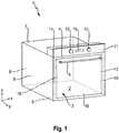
- the Fig. 1 shows a schematic perspective view of an embodiment of a domestic cooking appliance 1.
- the domestic cooking appliance 1 is preferably an oven, an oven with a steam cooking function, a microwave combination oven or the like.
- the household cooking appliance 1 has an oven muffle, muffle or a cooking space 2, which is with Can be locked using a door 3.
- the cooking space 2 can be arranged in the interior of a housing of the domestic cooking appliance 1.
- Door 3 is in the Fig. 1 shown in their closed position.
- the door 3 can be closed or opened by pivoting about a pivot axis provided at a lower end of the door 3.
- the door 3 can be hinged on the side of the cooking chamber 2.
- the door 3 can be arranged on a baking trolley that can be pulled out of the cooking space 2.
- a handle 5 can be provided on an upper section or an upper edge 4 of the door 3.
- the cooking chamber 2 has a floor 6, a ceiling 7 arranged opposite the floor 6, a rear wall 8 arranged opposite the closed door 3 and two side walls 9, 10 arranged opposite one another.
- the cooking space 2 is preferably cuboid or cube-shaped.
- the cooking chamber 2 can be made from a metal material, in particular from sheet steel.
- the domestic cooking appliance 1 further comprises control knobs 12, 13 provided on an operating panel 11.
- the control knobs 12, 13 can, for example, be rotatable.
- a control device 14 which is only shown schematically, can be provided for controlling the domestic cooking appliance 1.
- the control device 14 can be a regulating and / or control device.
- a display 15 can also be provided on the control panel 11. With the aid of the display 15, an operating state of the domestic cooking appliance 1 can be displayed. For example, with the aid of the display 15, a temperature set by means of the operating knobs 12, 13 can be displayed.
- the door 3 has several panes 16, of which in the Fig. 1 only one, namely a windshield, is shown. Furthermore, the door 3 comprises a first door profile 17 and a second door profile 18, which are spaced apart from one another and positioned parallel to one another.
- the door profiles 17, 18 can be attached to the rear of the pane 16, that is to say facing the cooking chamber 2, in particular glued to it.
- the door profiles 17, 18 run in a closed state of the door 3 along a z-direction z of the domestic cooking appliance 1. Furthermore, in FIG Fig. 1 an x-direction x and a y-direction y of the domestic cooking appliance 1 are also shown.
- the Fig. 2 shows a schematic partial sectional view of the door 3.
- the door 3 comprises several panes 16 and 19 to 21.
- the panes 16 and 19 to 21 can for example be made of a glass material and are at least partially transparent.
- the disk 19 can also be referred to as a first disk or inner disk
- the disk 20 can also be referred to as a second disk or first intermediate disk
- the disk 21 can also be referred to as a third disk or second inner disk
- the disk 16 can also be referred to as a fourth disk or front disk.
- the door profiles 17, 18 are preferably firmly connected, for example glued, to an inner surface 22 of the pane 16.
- Each door profile 17, 18 has a receiving section 23 for receiving the first pane 19.
- the receiving section 23 is designed, for example, in the shape of a hook and can encompass an edge 24, in particular an upper edge or a lower edge, of the first disk 19 at least in sections.
- Each door profile 17, 18 furthermore has a receiving section 25 which is set up to position the second pane 20 and the third pane 21 in the door 3.
- an edge 26, in particular an upper edge or a lower edge, of the second pane 20 and an edge 27, in particular an upper edge or a lower edge, of the third pane 21 can rest on the receiving section 25.
- the panes 16 and 19 to 21 can be arranged parallel to one another and at a distance from one another.
- Each disk 16 and 19 to 21 represents a plane.
- the second disk 20 is spaced apart from the first disk 19, the third disk 21 spaced apart from the second disk 20, and the fourth disk 16 spaced apart from the third disk 21.
- the distances between the disks 16 and 19 to 21 can be different or the same.
- Air can circulate between the disks 16 and 19 to 21.
- a first gap S1 is provided between the first disk 19 and the second disk 20
- a second gap S2 is provided between the second disk 20 and the third disk 21
- a third gap S3 is provided between the third disk 21 and the fourth disk 16.
- the door profiles 17, 18 are arranged between the first pane 19 and the fourth pane 16.
- the door profiles 17, 18 are, however, also arranged at least in sections between the first pane 19 and the second pane 20 and between the first pane 19 and the third pane 21.
- the door 3 further comprises a sealing device 28.
- the sealing device 28 is, as in FIG Fig. 2 shown, arranged between the first disc 19 and the second disc 20 in the first gap S1.
- the sealing device 28 can alternatively also be arranged between the second disk 20 and the third disk 21 or between the third disk 21 and the fourth disk 16.
- the sealing device 28 is fastened both to the first door profile 17 and to the second door profile 18.
- the sealing device 28 is positively connected to the first door profile 17 and the second door profile 18.
- a positive connection is created by the interlocking or interlocking of at least two connection partners, in this case the door profiles 17, 18 and the sealing device 28.
- the sealing device 28 is suspended in the first door profile 17 and the second door profile 18.
- the sealing device 28 is hooked into the door profiles 17, 18 under prestress.
- the one in the Fig. 3 Sealing device 28 shown in a schematic perspective view comprises an elastically deformable sealing element 29, which is made, for example, from a silicone material.
- the sealing element 29 extends perpendicular to the door profiles 17, 18 and is positioned between them.
- the sealing element 29 can have any geometry in cross section.
- the sealing element 29 can be designed to be hollow, at least in sections.
- the sealing element 29 comprises several sealing lips 30 to 33.
- the sealing lips 30, 31 are designed to seal the sealing element 29 against the first disk 19, and the sealing lips 32, 33 are designed to seal the sealing element 29 against the second disk 20.
- the sealing device 28 comprises a first hook 34 for hooking the sealing device 28 into the first door profile 17 and a second hook 35 for hooking the sealing device 28 into the second door profile 18.
- the hook 34, 35 are preferably made of a steel material.
- the suspension hooks 34, 35 can be connected to the sealing element 29 with a form fit or material fit. In the case of material connections, the connection partners are held together by atomic or molecular forces. Cohesive connections are non-detachable connections that can only be separated by destroying the connection means and / or the connection partner.
- the suspension hooks 34, 35 are glued to the sealing element 29.
- Each suspension hook 34, 35 comprises one Connecting section 36, which is firmly connected to the sealing element 29, a hooking section 37, which is arranged parallel to the connecting section 36, and an intermediate section 38, which connects the connecting section 36 to the hooking section 37.
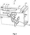
- the door profiles 17, 18 have, as in the Fig. 4 shown, each have a receiving section 39, in particular an opening or a bore.
- the sealing device 28 is suspended in the receiving sections 39, the hooking section 37 of the suspension hooks 34, 35 being passed through the receiving section 39.
- the receiving section 39 is designed, for example, as an opening breaking through a side wall 40 of the respective door profile 17, 18.
- the geometry of the receiving section 39 is arbitrary.
- the receiving section 39 can also be a circular bore.
- a groove section 41 arranged at a distance from it.
- the suspension hooks 34, 35 fixed to the respective door profile 17, 18. This defines the position of the sealing device 28 and it cannot slip.
- the sealing device 28 By hanging the sealing device 28 in the door profiles 17, 18, it is not necessary to fasten the sealing device 28 to one of the panes 19, 20, but can be used independently of the panes 19, 20 on the door profiles 17, which are connected to the fourth pane 16. 18 can be attached.
- the sealing device 28 can cover a greater width of the first gap S1 between the panes 19, 20 than if it is attached to only one of the panes 19, 20.
- the assembly of the sealing device 28 is clearly defined by the receiving sections 39 and the groove sections 41 on the door profiles 17, 18.
- the cross-sectional geometry and the material of the sealing element 29 are arbitrary.
- the sealing element 29 can also be made from a spring steel and formed in one piece with the suspension hooks 34, 35.
- the door profiles 17, 18 can be made of metal or plastic, for example.
- the Suspension hooks 34, 35 can also be made from a plastic material or from a silicone material.
- the sealing device 28 is preferably provided in a lower area or on a lower edge 43 of the door 3. The lower edge 43 is positioned facing away from the upper edge 4.
- the sealing device 28 can also be provided on the upper edge 4.
- each sealed gap can have a positive impact on energy consumption.
- Air circulation between certain panes 16 and 19 to 21, for example between panes 19, 20, is prevented and the door 3 can be ventilated between other panes 16 and 19 to 21, for example between panes 21, 16.
- the advantages of the domestic cooking appliance 1 are that the sealing device 28 is not mounted directly on one of the panes 16 and 19 to 21, but can be hooked directly into the door profiles 17, 18. In this way, the risk of one of the disks 16 and 19 to 21 being actuated by the suspension hooks 34, 35 can be prevented.
- the suspension hooks 34, 35 are securely installed in the receiving sections 39 of the door profiles 17, 18 and do not involve any risk of injury to a customer when the door 3 is dismantled and cleaned.
- the position of the sealing device 28 is guaranteed in a process-reliable manner. Incorrect assembly, for example too high or too low on one of the panes 16 and 19 to 21, both in production and by the customer when dismantling and cleaning the door 3, can be prevented and thus the function can also be ensured.
- the assembly of the sealing device 28 on the door profiles 17, 18 also makes the sealing device 28 independent of the geometry and size of the panes 16 and 19 to 21 and can therefore be used universally.
- the hanging hooks 34, 35 come to rest in the groove sections 41 of the door profiles 17, 18, it is not necessary to provide additional space for the hanging hooks 34, 35 between the first pane 19 and the second pane 20. As a result, the first gap S1 between the panes 19, 20 becomes larger, as a result of which improved air circulation is possible. In this way, improved energy efficiency can be achieved and a temperature of the fourth disk 16 can be reduced due to the insulating effect of the first gap S1.
Landscapes
- Engineering & Computer Science (AREA)
- Chemical & Material Sciences (AREA)
- Combustion & Propulsion (AREA)
- Mechanical Engineering (AREA)
- General Engineering & Computer Science (AREA)
- Securing Of Glass Panes Or The Like (AREA)
- Cookers (AREA)
- Electric Ovens (AREA)
Claims (8)
- Appareil de cuisson électroménager (1) comprenant un compartiment de cuisson (2) et une porte (3) permettant de fermer le compartiment de cuisson (2), dans lequel la porte (3) comprend une première vitre (19), une seconde vitre (20) agencée à distance de la première vitre (19), un premier profilé de porte (17), un second profilé de porte (18) agencé à distance du premier profilé de porte (17) et un dispositif d'étanchéité (28) qui est agencé dans une fente (S1) prévue entre la première vitre (19) et la seconde vitre (20) afin d'assurer l'étanchéité de la fente (S1), dans lequel le dispositif d'étanchéité (28) est fixé au premier profilé de porte (17) et au second profilé de porte (18),
caractérisé en ce que le dispositif d'étanchéité (28) est accroché dans le premier profilé de porte (17) et le second profilé de porte (18) sous précontrainte de telle sorte que le dispositif d'étanchéité (28) soit étiré de manière élastique pendant le montage de celui-ci et que cet allongement soit toujours maintenu, également après le montage du dispositif d'étanchéité (28). - Appareil de cuisson électroménager selon la revendication 1, caractérisé en ce que le dispositif d'étanchéité (28) est relié au premier profilé de porte (17) et au second profilé de porte (18) par complémentarité de forme.
- Appareil de cuisson électroménager selon la revendication 1 ou 2, caractérisé en ce que le dispositif d'étanchéité (28) présente un premier crochet d'accrochage (34) permettant d'accrocher le dispositif d'étanchéité (28) dans le premier profilé de porte (17) et un second crochet d'accrochage (35) permettant d'accrocher le dispositif d'étanchéité (28) dans le second profilé de porte (18).
- Appareil de cuisson électroménager selon la revendication 3, caractérisé en ce que le dispositif d'étanchéité (28) présente un élément d'étanchéité déformable de manière élastique (29) qui est agencé entre le premier crochet d'accrochage (34) et le second crochet d'accrochage (35) et est fermement lié à ceux-ci.
- Appareil de cuisson électroménager selon la revendication 4, caractérisé en ce que le premier crochet d'accrochage (34) et le second crochet d'accrochage (35) sont réalisés en un matériau d'acier et l'élément d'étanchéité (29) est réalisé en un matériau de silicone.
- Appareil de cuisson électroménager selon la revendication 4 ou 5, caractérisé en ce que l'élément d'étanchéité (29) présente des lèvres d'étanchéité (30 - 33) qui sont conçues afin de s'appuyer de manière étanche contre la première vitre (19) et/ou la seconde vitre (20).
- Appareil de cuisson électroménager selon l'une des revendications 3 - 6, caractérisé en ce que le premier profilé de porte (17) et le second profilé de porte (18) présentent chacun une section de réception (39), en particulier une ouverture, dans laquelle le dispositif d'étanchéité (28) est accroché.
- Appareil de cuisson électroménager selon l'une des revendications 3 - 7, caractérisé en ce que le premier profilé de porte (17) et le second profilé de porte (18) présentent chacun une section de rainure (41) dans laquelle sont insérés le premier crochet d'accrochage (34) et le second crochet d'accrochage (35).
Priority Applications (1)
| Application Number | Priority Date | Filing Date | Title |
|---|---|---|---|
| PL17816503T PL3551939T3 (pl) | 2016-12-12 | 2017-11-24 | Urządzenie gospodarstwa domowego do gotowania |
Applications Claiming Priority (2)
| Application Number | Priority Date | Filing Date | Title |
|---|---|---|---|
| DE102016224757.3A DE102016224757A1 (de) | 2016-12-12 | 2016-12-12 | Haushaltsgargerät |
| PCT/EP2017/080357 WO2018108483A1 (fr) | 2016-12-12 | 2017-11-24 | Appareil de cuisson électroménager |
Publications (2)
| Publication Number | Publication Date |
|---|---|
| EP3551939A1 EP3551939A1 (fr) | 2019-10-16 |
| EP3551939B1 true EP3551939B1 (fr) | 2021-04-07 |
Family
ID=60702616
Family Applications (1)
| Application Number | Title | Priority Date | Filing Date |
|---|---|---|---|
| EP17816503.1A Active EP3551939B1 (fr) | 2016-12-12 | 2017-11-24 | Appareil de cuisson ménager |
Country Status (6)
| Country | Link |
|---|---|
| US (1) | US10845061B2 (fr) |
| EP (1) | EP3551939B1 (fr) |
| CN (1) | CN110036242B (fr) |
| DE (1) | DE102016224757A1 (fr) |
| PL (1) | PL3551939T3 (fr) |
| WO (1) | WO2018108483A1 (fr) |
Families Citing this family (3)
| Publication number | Priority date | Publication date | Assignee | Title |
|---|---|---|---|---|
| TR201909193A2 (tr) * | 2019-06-20 | 2021-01-21 | Bsh Ev Aletleri San Ve Tic As | Ev ci̇hazi i̇çi̇n bi̇r kapi |
| DE102020209242A1 (de) | 2020-07-22 | 2022-01-27 | BSH Hausgeräte GmbH | Tür und Haushaltsgargerät |
| USD956466S1 (en) * | 2020-10-15 | 2022-07-05 | Samsung Electronics Co., Ltd. | Microwave |
Family Cites Families (16)
| Publication number | Priority date | Publication date | Assignee | Title |
|---|---|---|---|---|
| US3200812A (en) * | 1963-09-24 | 1965-08-17 | Mills Prod Inc | Oven door window unit |
| US3244165A (en) * | 1964-08-31 | 1966-04-05 | Borg Warner | Seal for glass oven door |
| DE4333033C1 (de) * | 1993-09-29 | 1995-05-24 | Schott Glas | Temperaturdämmendes Sichtfenster oder -türe für ein Gerät mit von seiner Umgebungstemperatur abweichender Innentemperatur |
| DE29503872U1 (de) * | 1995-03-07 | 1996-07-04 | AEG Hausgeräte GmbH, 90429 Nürnberg | Tür zum Verschließen der Ofenmuffel eines Back- und Bratofens |
| DE10138889B4 (de) | 2001-08-08 | 2004-04-08 | BSH Bosch und Siemens Hausgeräte GmbH | Backofentür-Dichtungsprofil und Backofentür |
| FR2830897B1 (fr) * | 2001-10-17 | 2006-11-17 | Saint Gobain | Vitrage isolant et son procede de fabrication |
| FR2846029B1 (fr) * | 2002-10-17 | 2005-07-01 | Saint Gobain | Vitrage isolant |
| DE10314214B4 (de) | 2003-03-28 | 2021-10-28 | BSH Hausgeräte GmbH | Ofentür zum Verschließen einer Ofenmuffel eines Backofens |
| DE102006027610A1 (de) | 2006-06-13 | 2007-12-20 | Electrolux Home Products Corporation N.V. | Tür zum Verschließen der Beschickungsöffnung eines Garraums eines Garofens, insbesondere eines Haushaltsgarofens |
| TR201005080A2 (tr) * | 2010-06-23 | 2010-12-21 | Vestel Beyaz Eşya Sanayi̇ Ve Ti̇caret Anoni̇m Şi̇rketi̇@ | Pişirici cihaz kapısı. |
| DE102011088082B4 (de) | 2011-12-09 | 2022-03-31 | BSH Hausgeräte GmbH | Tür für ein Haushaltsgerät sowie Haushaltsgerät mit einer Tür |
| DE102011088073B4 (de) | 2011-12-09 | 2024-08-01 | BSH Hausgeräte GmbH | Tür für ein Haushaltsgerät sowie Gargerät mit einer derartigen Tür |
| EP2938930B1 (fr) * | 2012-12-28 | 2017-08-02 | Arçelik Anonim Sirketi | Porte comprenant des panneaux détachables et four sur lequel la porte est utilisée |
| WO2015165499A1 (fr) | 2014-04-29 | 2015-11-05 | Arcelik Anonim Sirketi | Porte destinée à un four, pouvant être démontée/remontée plus facilement |
| DE102015108618A1 (de) * | 2015-06-01 | 2016-12-01 | Miele & Cie. Kg | Garraummuffel |
| CN205227439U (zh) * | 2015-11-27 | 2016-05-11 | 广东沃尔姆斯电器有限公司 | 易拆结构的多层门体 |
-
2016
- 2016-12-12 DE DE102016224757.3A patent/DE102016224757A1/de not_active Withdrawn
-
2017
- 2017-11-24 PL PL17816503T patent/PL3551939T3/pl unknown
- 2017-11-24 CN CN201780076562.6A patent/CN110036242B/zh active Active
- 2017-11-24 WO PCT/EP2017/080357 patent/WO2018108483A1/fr not_active Ceased
- 2017-11-24 EP EP17816503.1A patent/EP3551939B1/fr active Active
- 2017-11-24 US US16/320,561 patent/US10845061B2/en active Active
Non-Patent Citations (1)
| Title |
|---|
| None * |
Also Published As
| Publication number | Publication date |
|---|---|
| PL3551939T3 (pl) | 2021-10-25 |
| US20190242588A1 (en) | 2019-08-08 |
| EP3551939A1 (fr) | 2019-10-16 |
| WO2018108483A1 (fr) | 2018-06-21 |
| DE102016224757A1 (de) | 2018-06-14 |
| CN110036242B (zh) | 2021-02-05 |
| US10845061B2 (en) | 2020-11-24 |
| CN110036242A (zh) | 2019-07-19 |
Similar Documents
| Publication | Publication Date | Title |
|---|---|---|
| EP3551938B1 (fr) | Appareil ménager | |
| DE10051643B4 (de) | Haube für einen Lüfterfilter | |
| EP3551939B1 (fr) | Appareil de cuisson ménager | |
| WO1999022177A1 (fr) | Appareil menager a panneau frontal | |
| DE102009028808A1 (de) | Innenrahmen für Dunstabzugshaube und Dunstabzugshaube | |
| EP4185811A1 (fr) | Porte et appareil ménager de cuisson | |
| EP1867927A2 (fr) | Porte d'un four de cuisson, en particulier un four de cuisson ménager, ainsi que procédé de fabrication | |
| EP2128529B1 (fr) | Moufle de four | |
| EP4185814B1 (fr) | Porte et dispositif de cuisson domestique | |
| EP2553343B1 (fr) | Porte de four et procédé pour fixer un habillage de porte à une telle porte de four | |
| WO2002044620A1 (fr) | Four de cuisson | |
| DE102010063906A1 (de) | Backofentür und Backofen mit einer Backofentür | |
| DE102011084571A1 (de) | Vorrichtung zur Behandlung von Lebensmitteln mit verbesserter Tür-Anbindung | |
| EP1160513A2 (fr) | Appareil domestique avec panneau de commande frontal | |
| DE102011088082A1 (de) | Tür für ein Haushaltsgerät sowie Haushaltsgerät mit einer Tür | |
| EP2634493B1 (fr) | Porte pour un appareil ménager destiné à préparer des produits alimentaires, dotée d'une pièce de support | |
| EP2430368B1 (fr) | Porte avec un élément support | |
| DE10328885B4 (de) | Wärmegerät, insbesondrere Backofen | |
| DE10106824B4 (de) | Gargeräterahmen sowie Gargerät | |
| WO2019091791A1 (fr) | Appareil de cuisson électroménager comprenant un compartiment de cuisson | |
| EP1548367B1 (fr) | Dispositif pour la fermeture de l'orifice d'enceinte d'un appareil ménager | |
| DE102009045343A1 (de) | Kältegerät mit Ventilatorbaugruppe | |
| DE102020209247A1 (de) | Tür und Haushaltsgargerät | |
| EP2740871B1 (fr) | Dispositif destiné à un appareil ménager comprenant une charnière et un dispositif de couplage et appareil ménager doté d'un tel dispositif | |
| EP1726884A1 (fr) | Porte d'un four cuisinière |
Legal Events
| Date | Code | Title | Description |
|---|---|---|---|
| STAA | Information on the status of an ep patent application or granted ep patent |
Free format text: STATUS: UNKNOWN |
|
| STAA | Information on the status of an ep patent application or granted ep patent |
Free format text: STATUS: THE INTERNATIONAL PUBLICATION HAS BEEN MADE |
|
| PUAI | Public reference made under article 153(3) epc to a published international application that has entered the european phase |
Free format text: ORIGINAL CODE: 0009012 |
|
| STAA | Information on the status of an ep patent application or granted ep patent |
Free format text: STATUS: REQUEST FOR EXAMINATION WAS MADE |
|
| 17P | Request for examination filed |
Effective date: 20190712 |
|
| AK | Designated contracting states |
Kind code of ref document: A1 Designated state(s): AL AT BE BG CH CY CZ DE DK EE ES FI FR GB GR HR HU IE IS IT LI LT LU LV MC MK MT NL NO PL PT RO RS SE SI SK SM TR |
|
| AX | Request for extension of the european patent |
Extension state: BA ME |
|
| DAV | Request for validation of the european patent (deleted) | ||
| DAX | Request for extension of the european patent (deleted) | ||
| GRAP | Despatch of communication of intention to grant a patent |
Free format text: ORIGINAL CODE: EPIDOSNIGR1 |
|
| STAA | Information on the status of an ep patent application or granted ep patent |
Free format text: STATUS: GRANT OF PATENT IS INTENDED |
|
| INTG | Intention to grant announced |
Effective date: 20201120 |
|
| GRAS | Grant fee paid |
Free format text: ORIGINAL CODE: EPIDOSNIGR3 |
|
| GRAA | (expected) grant |
Free format text: ORIGINAL CODE: 0009210 |
|
| STAA | Information on the status of an ep patent application or granted ep patent |
Free format text: STATUS: THE PATENT HAS BEEN GRANTED |
|
| AK | Designated contracting states |
Kind code of ref document: B1 Designated state(s): AL AT BE BG CH CY CZ DE DK EE ES FI FR GB GR HR HU IE IS IT LI LT LU LV MC MK MT NL NO PL PT RO RS SE SI SK SM TR |
|
| REG | Reference to a national code |
Ref country code: GB Ref legal event code: FG4D Free format text: NOT ENGLISH |
|
| REG | Reference to a national code |
Ref country code: AT Ref legal event code: REF Ref document number: 1380169 Country of ref document: AT Kind code of ref document: T Effective date: 20210415 Ref country code: CH Ref legal event code: EP |
|
| REG | Reference to a national code |
Ref country code: DE Ref legal event code: R096 Ref document number: 502017010034 Country of ref document: DE |
|
| REG | Reference to a national code |
Ref country code: IE Ref legal event code: FG4D Free format text: LANGUAGE OF EP DOCUMENT: GERMAN |
|
| REG | Reference to a national code |
Ref country code: LT Ref legal event code: MG9D |
|
| REG | Reference to a national code |
Ref country code: NL Ref legal event code: MP Effective date: 20210407 |
|
| PG25 | Lapsed in a contracting state [announced via postgrant information from national office to epo] |
Ref country code: BG Free format text: LAPSE BECAUSE OF FAILURE TO SUBMIT A TRANSLATION OF THE DESCRIPTION OR TO PAY THE FEE WITHIN THE PRESCRIBED TIME-LIMIT Effective date: 20210707 Ref country code: HR Free format text: LAPSE BECAUSE OF FAILURE TO SUBMIT A TRANSLATION OF THE DESCRIPTION OR TO PAY THE FEE WITHIN THE PRESCRIBED TIME-LIMIT Effective date: 20210407 Ref country code: NL Free format text: LAPSE BECAUSE OF FAILURE TO SUBMIT A TRANSLATION OF THE DESCRIPTION OR TO PAY THE FEE WITHIN THE PRESCRIBED TIME-LIMIT Effective date: 20210407 Ref country code: LT Free format text: LAPSE BECAUSE OF FAILURE TO SUBMIT A TRANSLATION OF THE DESCRIPTION OR TO PAY THE FEE WITHIN THE PRESCRIBED TIME-LIMIT Effective date: 20210407 Ref country code: FI Free format text: LAPSE BECAUSE OF FAILURE TO SUBMIT A TRANSLATION OF THE DESCRIPTION OR TO PAY THE FEE WITHIN THE PRESCRIBED TIME-LIMIT Effective date: 20210407 |
|
| PG25 | Lapsed in a contracting state [announced via postgrant information from national office to epo] |
Ref country code: IS Free format text: LAPSE BECAUSE OF FAILURE TO SUBMIT A TRANSLATION OF THE DESCRIPTION OR TO PAY THE FEE WITHIN THE PRESCRIBED TIME-LIMIT Effective date: 20210807 Ref country code: GR Free format text: LAPSE BECAUSE OF FAILURE TO SUBMIT A TRANSLATION OF THE DESCRIPTION OR TO PAY THE FEE WITHIN THE PRESCRIBED TIME-LIMIT Effective date: 20210708 Ref country code: NO Free format text: LAPSE BECAUSE OF FAILURE TO SUBMIT A TRANSLATION OF THE DESCRIPTION OR TO PAY THE FEE WITHIN THE PRESCRIBED TIME-LIMIT Effective date: 20210707 Ref country code: PT Free format text: LAPSE BECAUSE OF FAILURE TO SUBMIT A TRANSLATION OF THE DESCRIPTION OR TO PAY THE FEE WITHIN THE PRESCRIBED TIME-LIMIT Effective date: 20210809 Ref country code: LV Free format text: LAPSE BECAUSE OF FAILURE TO SUBMIT A TRANSLATION OF THE DESCRIPTION OR TO PAY THE FEE WITHIN THE PRESCRIBED TIME-LIMIT Effective date: 20210407 Ref country code: RS Free format text: LAPSE BECAUSE OF FAILURE TO SUBMIT A TRANSLATION OF THE DESCRIPTION OR TO PAY THE FEE WITHIN THE PRESCRIBED TIME-LIMIT Effective date: 20210407 Ref country code: SE Free format text: LAPSE BECAUSE OF FAILURE TO SUBMIT A TRANSLATION OF THE DESCRIPTION OR TO PAY THE FEE WITHIN THE PRESCRIBED TIME-LIMIT Effective date: 20210407 |
|
| REG | Reference to a national code |
Ref country code: DE Ref legal event code: R097 Ref document number: 502017010034 Country of ref document: DE |
|
| PG25 | Lapsed in a contracting state [announced via postgrant information from national office to epo] |
Ref country code: SM Free format text: LAPSE BECAUSE OF FAILURE TO SUBMIT A TRANSLATION OF THE DESCRIPTION OR TO PAY THE FEE WITHIN THE PRESCRIBED TIME-LIMIT Effective date: 20210407 Ref country code: SK Free format text: LAPSE BECAUSE OF FAILURE TO SUBMIT A TRANSLATION OF THE DESCRIPTION OR TO PAY THE FEE WITHIN THE PRESCRIBED TIME-LIMIT Effective date: 20210407 Ref country code: ES Free format text: LAPSE BECAUSE OF FAILURE TO SUBMIT A TRANSLATION OF THE DESCRIPTION OR TO PAY THE FEE WITHIN THE PRESCRIBED TIME-LIMIT Effective date: 20210407 Ref country code: EE Free format text: LAPSE BECAUSE OF FAILURE TO SUBMIT A TRANSLATION OF THE DESCRIPTION OR TO PAY THE FEE WITHIN THE PRESCRIBED TIME-LIMIT Effective date: 20210407 Ref country code: DK Free format text: LAPSE BECAUSE OF FAILURE TO SUBMIT A TRANSLATION OF THE DESCRIPTION OR TO PAY THE FEE WITHIN THE PRESCRIBED TIME-LIMIT Effective date: 20210407 Ref country code: CZ Free format text: LAPSE BECAUSE OF FAILURE TO SUBMIT A TRANSLATION OF THE DESCRIPTION OR TO PAY THE FEE WITHIN THE PRESCRIBED TIME-LIMIT Effective date: 20210407 Ref country code: RO Free format text: LAPSE BECAUSE OF FAILURE TO SUBMIT A TRANSLATION OF THE DESCRIPTION OR TO PAY THE FEE WITHIN THE PRESCRIBED TIME-LIMIT Effective date: 20210407 |
|
| PLBE | No opposition filed within time limit |
Free format text: ORIGINAL CODE: 0009261 |
|
| STAA | Information on the status of an ep patent application or granted ep patent |
Free format text: STATUS: NO OPPOSITION FILED WITHIN TIME LIMIT |
|
| 26N | No opposition filed |
Effective date: 20220110 |
|
| PG25 | Lapsed in a contracting state [announced via postgrant information from national office to epo] |
Ref country code: IS Free format text: LAPSE BECAUSE OF FAILURE TO SUBMIT A TRANSLATION OF THE DESCRIPTION OR TO PAY THE FEE WITHIN THE PRESCRIBED TIME-LIMIT Effective date: 20210807 Ref country code: AL Free format text: LAPSE BECAUSE OF FAILURE TO SUBMIT A TRANSLATION OF THE DESCRIPTION OR TO PAY THE FEE WITHIN THE PRESCRIBED TIME-LIMIT Effective date: 20210407 |
|
| PG25 | Lapsed in a contracting state [announced via postgrant information from national office to epo] |
Ref country code: MC Free format text: LAPSE BECAUSE OF FAILURE TO SUBMIT A TRANSLATION OF THE DESCRIPTION OR TO PAY THE FEE WITHIN THE PRESCRIBED TIME-LIMIT Effective date: 20210407 |
|
| REG | Reference to a national code |
Ref country code: CH Ref legal event code: PL |
|
| PG25 | Lapsed in a contracting state [announced via postgrant information from national office to epo] |
Ref country code: LU Free format text: LAPSE BECAUSE OF NON-PAYMENT OF DUE FEES Effective date: 20211124 Ref country code: IT Free format text: LAPSE BECAUSE OF FAILURE TO SUBMIT A TRANSLATION OF THE DESCRIPTION OR TO PAY THE FEE WITHIN THE PRESCRIBED TIME-LIMIT Effective date: 20210407 Ref country code: BE Free format text: LAPSE BECAUSE OF NON-PAYMENT OF DUE FEES Effective date: 20211130 |
|
| REG | Reference to a national code |
Ref country code: BE Ref legal event code: MM Effective date: 20211130 |
|
| PG25 | Lapsed in a contracting state [announced via postgrant information from national office to epo] |
Ref country code: LI Free format text: LAPSE BECAUSE OF NON-PAYMENT OF DUE FEES Effective date: 20211130 Ref country code: CH Free format text: LAPSE BECAUSE OF NON-PAYMENT OF DUE FEES Effective date: 20211130 |
|
| PG25 | Lapsed in a contracting state [announced via postgrant information from national office to epo] |
Ref country code: IE Free format text: LAPSE BECAUSE OF NON-PAYMENT OF DUE FEES Effective date: 20211124 |
|
| P01 | Opt-out of the competence of the unified patent court (upc) registered |
Effective date: 20230504 |
|
| PG25 | Lapsed in a contracting state [announced via postgrant information from national office to epo] |
Ref country code: CY Free format text: LAPSE BECAUSE OF FAILURE TO SUBMIT A TRANSLATION OF THE DESCRIPTION OR TO PAY THE FEE WITHIN THE PRESCRIBED TIME-LIMIT Effective date: 20210407 |
|
| PG25 | Lapsed in a contracting state [announced via postgrant information from national office to epo] |
Ref country code: HU Free format text: LAPSE BECAUSE OF FAILURE TO SUBMIT A TRANSLATION OF THE DESCRIPTION OR TO PAY THE FEE WITHIN THE PRESCRIBED TIME-LIMIT; INVALID AB INITIO Effective date: 20171124 |
|
| REG | Reference to a national code |
Ref country code: AT Ref legal event code: MM01 Ref document number: 1380169 Country of ref document: AT Kind code of ref document: T Effective date: 20221124 |
|
| PG25 | Lapsed in a contracting state [announced via postgrant information from national office to epo] |
Ref country code: AT Free format text: LAPSE BECAUSE OF NON-PAYMENT OF DUE FEES Effective date: 20221124 |
|
| PG25 | Lapsed in a contracting state [announced via postgrant information from national office to epo] |
Ref country code: MK Free format text: LAPSE BECAUSE OF FAILURE TO SUBMIT A TRANSLATION OF THE DESCRIPTION OR TO PAY THE FEE WITHIN THE PRESCRIBED TIME-LIMIT Effective date: 20210407 |
|
| PG25 | Lapsed in a contracting state [announced via postgrant information from national office to epo] |
Ref country code: MT Free format text: LAPSE BECAUSE OF FAILURE TO SUBMIT A TRANSLATION OF THE DESCRIPTION OR TO PAY THE FEE WITHIN THE PRESCRIBED TIME-LIMIT Effective date: 20210407 |
|
| PGFP | Annual fee paid to national office [announced via postgrant information from national office to epo] |
Ref country code: DE Payment date: 20251130 Year of fee payment: 9 |
|
| PGFP | Annual fee paid to national office [announced via postgrant information from national office to epo] |
Ref country code: GB Payment date: 20251120 Year of fee payment: 9 |
|
| PGFP | Annual fee paid to national office [announced via postgrant information from national office to epo] |
Ref country code: FR Payment date: 20251120 Year of fee payment: 9 |
|
| PGFP | Annual fee paid to national office [announced via postgrant information from national office to epo] |
Ref country code: TR Payment date: 20251118 Year of fee payment: 9 |
|
| PGFP | Annual fee paid to national office [announced via postgrant information from national office to epo] |
Ref country code: PL Payment date: 20251113 Year of fee payment: 9 |