EP3551915B1 - Bypass-ventil und molch mit einem bypass-ventil - Google Patents
Bypass-ventil und molch mit einem bypass-ventil Download PDFInfo
- Publication number
- EP3551915B1 EP3551915B1 EP17818076.6A EP17818076A EP3551915B1 EP 3551915 B1 EP3551915 B1 EP 3551915B1 EP 17818076 A EP17818076 A EP 17818076A EP 3551915 B1 EP3551915 B1 EP 3551915B1
- Authority
- EP
- European Patent Office
- Prior art keywords
- bypass valve
- piston
- storage means
- pig
- pressure
- Prior art date
- Legal status (The legal status is an assumption and is not a legal conclusion. Google has not performed a legal analysis and makes no representation as to the accuracy of the status listed.)
- Active
Links
Images


Classifications
-
- B—PERFORMING OPERATIONS; TRANSPORTING
- B08—CLEANING
- B08B—CLEANING IN GENERAL; PREVENTION OF FOULING IN GENERAL
- B08B9/00—Cleaning hollow articles by methods or apparatus specially adapted thereto
- B08B9/02—Cleaning pipes or tubes or systems of pipes or tubes
- B08B9/027—Cleaning the internal surfaces; Removal of blockages
- B08B9/04—Cleaning the internal surfaces; Removal of blockages using cleaning devices introduced into and moved along the pipes
- B08B9/053—Cleaning the internal surfaces; Removal of blockages using cleaning devices introduced into and moved along the pipes moved along the pipes by a fluid, e.g. by fluid pressure or by suction
- B08B9/055—Cleaning the internal surfaces; Removal of blockages using cleaning devices introduced into and moved along the pipes moved along the pipes by a fluid, e.g. by fluid pressure or by suction the cleaning devices conforming to, or being conformable to, substantially the same cross-section of the pipes, e.g. pigs or moles
- B08B9/0551—Control mechanisms therefor
-
- B—PERFORMING OPERATIONS; TRANSPORTING
- B08—CLEANING
- B08B—CLEANING IN GENERAL; PREVENTION OF FOULING IN GENERAL
- B08B9/00—Cleaning hollow articles by methods or apparatus specially adapted thereto
- B08B9/02—Cleaning pipes or tubes or systems of pipes or tubes
- B08B9/027—Cleaning the internal surfaces; Removal of blockages
- B08B9/04—Cleaning the internal surfaces; Removal of blockages using cleaning devices introduced into and moved along the pipes
- B08B9/053—Cleaning the internal surfaces; Removal of blockages using cleaning devices introduced into and moved along the pipes moved along the pipes by a fluid, e.g. by fluid pressure or by suction
- B08B9/055—Cleaning the internal surfaces; Removal of blockages using cleaning devices introduced into and moved along the pipes moved along the pipes by a fluid, e.g. by fluid pressure or by suction the cleaning devices conforming to, or being conformable to, substantially the same cross-section of the pipes, e.g. pigs or moles
- B08B9/0557—Pigs with rings shaped cleaning members, e.g. cup shaped pigs
-
- F—MECHANICAL ENGINEERING; LIGHTING; HEATING; WEAPONS; BLASTING
- F16—ENGINEERING ELEMENTS AND UNITS; GENERAL MEASURES FOR PRODUCING AND MAINTAINING EFFECTIVE FUNCTIONING OF MACHINES OR INSTALLATIONS; THERMAL INSULATION IN GENERAL
- F16K—VALVES; TAPS; COCKS; ACTUATING-FLOATS; DEVICES FOR VENTING OR AERATING
- F16K17/00—Safety valves; Equalising valves, e.g. pressure relief valves
- F16K17/02—Safety valves; Equalising valves, e.g. pressure relief valves opening on surplus pressure on one side; closing on insufficient pressure on one side
- F16K17/04—Safety valves; Equalising valves, e.g. pressure relief valves opening on surplus pressure on one side; closing on insufficient pressure on one side spring-loaded
- F16K17/044—Safety valves; Equalising valves, e.g. pressure relief valves opening on surplus pressure on one side; closing on insufficient pressure on one side spring-loaded with more than one spring
-
- F—MECHANICAL ENGINEERING; LIGHTING; HEATING; WEAPONS; BLASTING
- F16—ENGINEERING ELEMENTS AND UNITS; GENERAL MEASURES FOR PRODUCING AND MAINTAINING EFFECTIVE FUNCTIONING OF MACHINES OR INSTALLATIONS; THERMAL INSULATION IN GENERAL
- F16K—VALVES; TAPS; COCKS; ACTUATING-FLOATS; DEVICES FOR VENTING OR AERATING
- F16K17/00—Safety valves; Equalising valves, e.g. pressure relief valves
- F16K17/02—Safety valves; Equalising valves, e.g. pressure relief valves opening on surplus pressure on one side; closing on insufficient pressure on one side
- F16K17/04—Safety valves; Equalising valves, e.g. pressure relief valves opening on surplus pressure on one side; closing on insufficient pressure on one side spring-loaded
- F16K17/048—Safety valves; Equalising valves, e.g. pressure relief valves opening on surplus pressure on one side; closing on insufficient pressure on one side spring-loaded combined with other safety valves, or with pressure control devices
-
- F—MECHANICAL ENGINEERING; LIGHTING; HEATING; WEAPONS; BLASTING
- F16—ENGINEERING ELEMENTS AND UNITS; GENERAL MEASURES FOR PRODUCING AND MAINTAINING EFFECTIVE FUNCTIONING OF MACHINES OR INSTALLATIONS; THERMAL INSULATION IN GENERAL
- F16K—VALVES; TAPS; COCKS; ACTUATING-FLOATS; DEVICES FOR VENTING OR AERATING
- F16K17/00—Safety valves; Equalising valves, e.g. pressure relief valves
- F16K17/20—Excess-flow valves
- F16K17/22—Excess-flow valves actuated by the difference of pressure between two places in the flow line
- F16K17/24—Excess-flow valves actuated by the difference of pressure between two places in the flow line acting directly on the cutting-off member
- F16K17/28—Excess-flow valves actuated by the difference of pressure between two places in the flow line acting directly on the cutting-off member operating in one direction only
- F16K17/30—Excess-flow valves actuated by the difference of pressure between two places in the flow line acting directly on the cutting-off member operating in one direction only spring-loaded
-
- F—MECHANICAL ENGINEERING; LIGHTING; HEATING; WEAPONS; BLASTING
- F16—ENGINEERING ELEMENTS AND UNITS; GENERAL MEASURES FOR PRODUCING AND MAINTAINING EFFECTIVE FUNCTIONING OF MACHINES OR INSTALLATIONS; THERMAL INSULATION IN GENERAL
- F16L—PIPES; JOINTS OR FITTINGS FOR PIPES; SUPPORTS FOR PIPES, CABLES OR PROTECTIVE TUBING; MEANS FOR THERMAL INSULATION IN GENERAL
- F16L55/00—Devices or appurtenances for use in, or in connection with, pipes or pipe systems
- F16L55/26—Pigs or moles, i.e. devices movable in a pipe or conduit with or without self-contained propulsion means
- F16L55/28—Constructional aspects
- F16L55/30—Constructional aspects of the propulsion means, e.g. towed by cables
- F16L55/38—Constructional aspects of the propulsion means, e.g. towed by cables driven by fluid pressure
-
- G—PHYSICS
- G01—MEASURING; TESTING
- G01M—TESTING STATIC OR DYNAMIC BALANCE OF MACHINES OR STRUCTURES; TESTING OF STRUCTURES OR APPARATUS, NOT OTHERWISE PROVIDED FOR
- G01M3/00—Investigating fluid-tightness of structures
- G01M3/005—Investigating fluid-tightness of structures using pigs or moles
-
- B—PERFORMING OPERATIONS; TRANSPORTING
- B08—CLEANING
- B08B—CLEANING IN GENERAL; PREVENTION OF FOULING IN GENERAL
- B08B2209/00—Details of machines or methods for cleaning hollow articles
- B08B2209/02—Details of apparatuses or methods for cleaning pipes or tubes
- B08B2209/027—Details of apparatuses or methods for cleaning pipes or tubes for cleaning the internal surfaces
- B08B2209/04—Details of apparatuses or methods for cleaning pipes or tubes for cleaning the internal surfaces using cleaning devices introduced into and moved along the pipes
- B08B2209/053—Details of apparatuses or methods for cleaning pipes or tubes for cleaning the internal surfaces using cleaning devices introduced into and moved along the pipes being moved along the pipes by a fluid, e.g. by fluid pressure or by suction
- B08B2209/055—Details of apparatuses or methods for cleaning pipes or tubes for cleaning the internal surfaces using cleaning devices introduced into and moved along the pipes being moved along the pipes by a fluid, e.g. by fluid pressure or by suction the cleaning devices conforming to, or being conformable to, substantially the same cross-section of the pipes, e.g. pigs or moles
-
- F—MECHANICAL ENGINEERING; LIGHTING; HEATING; WEAPONS; BLASTING
- F16—ENGINEERING ELEMENTS AND UNITS; GENERAL MEASURES FOR PRODUCING AND MAINTAINING EFFECTIVE FUNCTIONING OF MACHINES OR INSTALLATIONS; THERMAL INSULATION IN GENERAL
- F16L—PIPES; JOINTS OR FITTINGS FOR PIPES; SUPPORTS FOR PIPES, CABLES OR PROTECTIVE TUBING; MEANS FOR THERMAL INSULATION IN GENERAL
- F16L2101/00—Uses or applications of pigs or moles
- F16L2101/10—Treating the inside of pipes
- F16L2101/12—Cleaning
-
- F—MECHANICAL ENGINEERING; LIGHTING; HEATING; WEAPONS; BLASTING
- F16—ENGINEERING ELEMENTS AND UNITS; GENERAL MEASURES FOR PRODUCING AND MAINTAINING EFFECTIVE FUNCTIONING OF MACHINES OR INSTALLATIONS; THERMAL INSULATION IN GENERAL
- F16L—PIPES; JOINTS OR FITTINGS FOR PIPES; SUPPORTS FOR PIPES, CABLES OR PROTECTIVE TUBING; MEANS FOR THERMAL INSULATION IN GENERAL
- F16L2101/00—Uses or applications of pigs or moles
- F16L2101/30—Inspecting, measuring or testing
Definitions
- the present invention relates to a bypass valve for an inspection and / or cleaning pig, which is to be moved through a pipeline through which the medium flows, the bypass valve comprising an interior space provided with a flow profile in which a longitudinal direction of the valve over a Force storage means is arranged pressure-dependently movable piston which is movable between a first, a bypass for the medium allowing open position of the valve and a second, the bypass at least substantially closing position.
- pigs which are designed as steel bodies with polyurethane discs of different hardness or polyurethane sleeves, have proven to be the most effective and flexible.
- the pig is driven through the line with the medium to be transported.
- the cleaning pig pushes out deposit material that comes out of the borehole with the gas and is deposited in the pipe.
- the cleaning effect or the quality of the pipeline data recorded during an inspection decreases rapidly, which can lead to problems in particular in gas pipelines in which gas is driven through the pipeline at high speed.
- the US 2010/0170535 A1 an object according to the preamble of claim 1 known, in which a piston on the one hand during the insertion of the pig in the Pipeline and, on the other hand, can also change almost instantaneously during a journey through the pipeline between an open position and a closed position that essentially closes the bypass. Before the run, the force exerted by this on the piston can be changed by setting a force storage device.
- the pig can thus be adapted to the pipeline conditions to a small extent.
- the piston can be transferred further into a maximum position that opens the bypass again.
- the flow cross-section released in the maximum position is significantly smaller than the free flow cross-section present in the first position and is furthermore significantly larger than the cross-section present in the closed position or the second position of the piston. Any free cross-section for a leakage flow is only there to prevent the piston from jamming.
- the pig or even the pig can be destroyed, especially in the case of often unforeseeable extreme obstacles, such as, for example, very large bumps in which the pig remains completely stuck Pipeline can be avoided.
- the differential pressure between the pipeline areas upstream and downstream of the pig or the corresponding bypass valve increases extreme and the piston goes into the maximum position when a preferably adjustable opening pressure of at least 5, preferably at least 7 or 8 bar and up to 14 bar is applied, so that the bypass is opened again and the maximum pressure is reduced. This ensures the integrity of the system and prevents total shutdown of the pipeline if the pig gets stuck.
- the piston in a region of the interior, is preferably designed to assume intermediate positions between the first and second positions, in particular in a drive pressure range between 0.01 and 0.5, in particular between 0.02 and 0.4 bar, depending on the pressure, to enable a pressure-regulated volume flow through the bypass valve.
- the piston Viewed in the longitudinal and through-flow direction of the bypass valve, the piston is therefore preferably initially in an open position, further advanced in the case of a greater differential pressure, then in a central position in an at least substantially closed position and then further advanced from a critical opening pressure in a maximum position which allows a flow through the bypass valve that is necessary under extreme conditions.
- the piston is located with its maximum cross-sectional area in the maximum position in a widened area of the interior of the bypass valve that is displaced forward or forwardly with respect to a flow direction.
- the flow profile of the interior and / or the profile of the piston is flow-optimized in such a way that in at least 50% of the drive pressure range the The volume flow passed through the bypass valve does not change by more than 60%.
- the form required for this can, for example, be found for each bypass valve using calculation methods based on empirical observations and can thus be defined for the respective bypass valve used depending on the respective pipeline conditions and media used. With such a pressure-regulated actuation of the bypass valve, the pig remains longer in the desired speed range.
- the profile of the interior or the interior of the valve initially tapers uniformly, in order then to narrow significantly more in the transition area to a central valve area. Then there is an interior area with a constant internal diameter, the interior then again widening again with a particularly steeper absolute slope than in the tapering area. This greater degree of expansion is in particular for the sudden application of an opening pressure This makes sense in order to avoid the risk of damage to the pig / bypass valve or the pipeline, which arises especially with almost incompressible media.
- the tapering and widening areas are designed in a flow-optimized manner in such a way that a flow that is as laminar as possible is generated.
- the piston profile is based on the tapering area in such a way that with increasing travel in the longitudinal direction, the free cross-section available for flow changes to an extent that enables a volume flow that is as constant as possible depending on the pressure.
- the bypass is large enough and takes up to 25% of the line cross-section to achieve a significant speed reduction.
- the passage space in the valve has thus been adapted in such a way that the volume flow can be kept constant over a large area through the bypass.
- the working range of the bypass valve can be adapted by changing the energy storage means (s).
- the construction is relatively mechanically simple and safe if the piston has a hollow rod area in which the energy storage means is at least partially arranged and is guided via a central bolt.
- the maximum position is advantageously adopted against the change, in particular the compression of a second energy storage means and / or after the pressure-dependent release of an additional piston working path.
- a practicable overpressure switching of the bypass valve can be achieved precisely by using two energy storage means designed with different work areas, whereby these can be designed according to the desired or existing conditions and line framework conditions by using, for example, springs or gas pressure cylinders as energy storage means.
- the two energy storage means are preferably designed in such a way that, starting from the closed position, the second energy storage means is compressed more in the longitudinal direction to a maximum position than the first energy storage means.
- the first energy storage means can then be a compressed spring that is no longer compressible or only minimally compressible, while the further, second energy storage means can only be significantly compressed in the longitudinal direction when the desired opening pressure is applied.
- the second energy storage means can be a plurality of plate springs arranged one behind the other in the longitudinal direction, the spring constants of which are significantly greater than those of a spiral spring previously used for normal operation of the bypass valve.
- bypass valve can also be made shorter in the central area and the design of the bypass valve can be better adapted to the respective framework conditions.
- the two energy storage means are advantageously arranged one behind the other and adjacent to one another when viewed in the longitudinal direction, it also being possible for them to abut one another by means of insert disks located in between, preferably guided via a central bolt.
- bypass valve The effects resulting from the construction of the bypass valve are particularly present when the bypass valve is used in a pig for the inspection and / or cleaning of pipelines. Accordingly, the object set out at the beginning is achieved both by a pig in which the bypass valve described above or below is arranged in a central body of the pig, and by a pig for inspection and / or cleaning of pipelines, in which the central body is at least formed by the preferably hollow cylindrical bypass valve on the outside.
- a cleaning pig 1 comprises according to Fig. 1 a central body 2 on which collars 4 fastened via flanges 3 are arranged. A pipeline is cleaned with these.
- the central body 2 is hollow and has a central bolt 7 held by three inner spacers 6 (cf. Fig. 2 ).
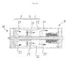
- a bypass valve 8 according to the invention (cf. Fig. 4 a) ) arranged in the hollow central body 2.
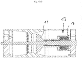
- the spacers 6 are part of the bypass valve. They hold the central bolt 7, which is used to guide a piston 11 and two energy storage means 12, 13.
- the energy storage means 12 is partially in a hollow rod area a piston rod region 14 and designed as a spiral spring.
- the further energy storage means 13 comprises a plurality of plate springs 16 arranged next to one another, which are arranged in hollow cylindrical shells 17 which can be moved against one another.
- the first energy storage means is arranged on the left hollow cylindrical shell 17, so that the two energy storage means lie one after the other in the longitudinal direction F, which also corresponds to the general flow direction.
- the inspection pig 1 has an inflow area 18 and an outflow area 19 through which the medium can enter the bypass valve 8 at one end and into which it reaches when it flows out of the valve 8 at the other end.
- the piston 11 also has this position in one of the exemplary embodiments according to the invention Fig. 4 a) , arrows 21 showing the direction of flow through the bypass valve 8.
- Fig. 4 a) the profile of the interior is made recognizable by the edges 22.
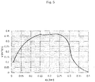
- this area A the flow profile of the interior and the profile of the piston are flow-optimized in such a way that in at least 50% of the drive pressure range of preferably 0.02 to 0.4 bar the volume flow passed through the bypass valve 8 does not change by more than 60% (cf. Fig. 5 ).
- area A for the bypass valve is the working area in a pressure range of up to 0.4 bar.
- area B which is shown with the associated piston position in FIG. 4 b), represents a working area of preferably 0.4 to 8 bar.
- the piston 11 is shown hatched in an intermediate position in which the piston 11 is displaced in the longitudinal direction F in a pressure-controlled manner is that the volumetric flow of the Fig. 5 curve shown.
- the hollow area formed by the area 14 of the piston rod can be designed in such a way that it extends the spiral spring 12 in its maximally compressed position in the longitudinal direction, so that the right end of the area 14 of the piston rod is flush with that in the Fig. 4 c) right end of the spiral spring 12 closes and thus press both ends on the vertical part of the hollow cylindrical shell 17, and thus compress the further energy storage means 13.
- the volume flow-pressure diagram according to Fig. 5 the pressure applied to the pig 1 from behind is shown on the X-axis and the resulting volume flow is shown on the Y-axis. It can be seen that the volume flow is designed in a comparatively plateau-like manner over a relatively large pressure range, so that the speed of the pig is as constant as possible or the pig does not reach speed ranges that are critical for cleaning or inspection.
Landscapes
- Engineering & Computer Science (AREA)
- General Engineering & Computer Science (AREA)
- Mechanical Engineering (AREA)
- Physics & Mathematics (AREA)
- Fluid Mechanics (AREA)
- Chemical & Material Sciences (AREA)
- Combustion & Propulsion (AREA)
- General Physics & Mathematics (AREA)
- Cleaning In General (AREA)
- Details Of Valves (AREA)
Description
- Die vorliegende Erfindung betrifft ein Bypass-Ventil für einen Inspektions- und/oder Reinigungsmolch, der durch eine Medium-durchströmte Rohrleitung zu bewegen ist, wobei das Bypass-Ventil einen mit einem Strömungsprofil versehenen Innenraum umfasst, in dem ein in Längsrichtung des Ventils über ein Kraftspeichermittel druckabhängig bewegbarer Kolben angeordnet ist, der zwischen einer ersten, einen Bypass für das Medium erlaubenden offenen Stellung des Ventils und einer zweiten, den Bypass zumindest im wesentlichen verschließenden Stellung beweglich ist.
- Für die Reinigung und Inspektion von Rohrleitungen haben sich Molche, die als Stahlkörper mit verschieden harten Polyurethan-Scheiben oder Polyurethan-Manschetten ausgeführt sind, als am effektivsten und flexibelsten erwiesen. Zur Reinigung oder Inspektion wird der Molch mit dem zu transportierenden Medium durch die Leitung getrieben. Hierbei schiebt der Reinigungsmolch zum Beispiel Lagerstättenmaterial, das mit dem Gas aus dem Bohrloch kommt und sich in der Leitung ablagert, heraus. Mit zunehmender Molchgeschwindigkeit nimmt die Reinigungswirkung bzw. die Qualität der bei einer Inspektion aufgenommen Daten der Rohrleitung rapide ab, was insbesondere in Gasleitungen, bei denen Gas mit hoher Geschwindigkeit durch die Rohrleitung getrieben wird, zu Problemen führen kann.
- Um dennoch eine effektive Reinigung bzw. Vermessung zu erzielen, ist aus der
US 2010/0170535 A1 ein Gegenstand nach dem Oberbegriff des Anspruchs 1 bekannt, bei dem ein Kolben einerseits während des Einsetzens des Molches in die Pipeline sowie andererseits auch während einer Fahrt durch die Pipeline zwischen einer offenen Position und einer im Wesentlichen den Bypass verschließenden geschlossenen Position nahezu instantan wechseln kann. Vor dem Lauf kann durch Einstellung eines Kraftspeichermittels die von diesem auf den Kolben ausgeübte Kraft verändert werden. Der Molch kann somit in einem geringen Maß an die Rohrleitungsbedingungen angepasst werden. - Damit der Molch an kleineren Hindernissen wie zum Beispiel Wandstärkensprüngen, Schweißnahtdurchgängen oder kleineren Beulen nicht stecken bleibt, wird aufgrund der durch erhöhte Reibung bewirkten Verlangsamung des Vortriebs eine Druckdifferenz aufgebaut, die bei einem bestimmten Wert den Kolben in die engste Position des Ventils presst. Das Ventil schließt, wobei ggf. ein ein Verklemmen des Ventils vermeidender Leckagestrom verbleibt, solange, bis der entstehende Druckanstieg zu einem Überwinden des Hindernisses und zu einer mitunter sehr hohen Beschleunigung des Molches führt. Der Kolben wird wieder in die geöffnete Position überführt, wenn sich die Druckdifferenz zwischen vor und hinter dem Molch wieder in einem ausreichenden Maß abgebaut hat.
- Mit den sich stark ändernden Geschwindigkeiten, insbesondere mit einer starken Beschleunigung nach einem Feststecken gehen Verschlechterungen der Reinigung bzw. Datenaufnahme einher, was im Extremfall zu einem erneuten Reinigungs- bzw. Inspektionslauf führen kann.
- Aus der
US 2,860,356 ist ein Reinigungsmolch bekannt, der eine Ventilanordnung zu entnehmen ist, in der ein Ventilmittel in einer Überdruck- bzw. Maximalposition komplett aus dem Ventilgehäuse heraustritt. - Es ist Aufgabe der vorliegenden Erfindung, die Geschwindigkeit eines durch die Leitung fahrenden Molches besser regulieren zu können.
- Die Aufgabe wird gelöst durch einen Gegenstand gemäß Anspruch 1. Vorteilhafte Ausgestaltungen der Erfindung sind den auf Anspruch 1 rückbezogenen Unteransprüchen zu entnehmen. Ebenfalls wird die Aufgabe durch Gegenstände nach den Ansprüchen 10 bzw. 11 gelöst. Vorteilhafte Ausgestaltungen sind jeweils der nachfolgenden Beschreibung zu entnehmen.
- Erfindungsgemäß ist der Kolben ausgehend von der ersten Stellung über die zweite Stellung in dieselbe Richtung weiter in eine den Bypass wieder öffnende Maximalstellung überführbar. Es versteht sich, dass der in der Maximalstellung freigegebene Strömungsquerschnitt deutlich kleiner ist als der in der ersten Stellung vorhandene freie Strömungsquerschnitt und weiterhin deutlich größer ist als der in der Verschlussstellung bzw. zweiten Stellung des Kolbens vorhandene Querschnitt. Ein etwaiger freier Querschnitt für einen Leckagestrom ist nur dazu da, ein Festklemmen des Kolbens zu verhindern.
- Durch die Möglichkeit, das Bypass-Ventil bzw. dessen Kolben in eine Maximalstellung zu überführen, kann insbesondere bei oftmals nicht absehbaren Extrem-Hindernissen, wie zum Beispiel sehr großen Beulen, bei denen der Molch vollständig stecken bleibt, eine Zerstörung des Molches oder gar der Rohrleitung vermieden werden. In einem solch extremen Fall erhöht sich der Differenzdruck zwischen den Rohrleitungsbereichen vor und hinter dem Molch bzw. dem entsprechenden Bypass-Ventil extrem und der Kolben geht bei Anliegen eines vorzugsweise einstellbaren Öffnungsdrucks von zumindest 5, vorzugsweise zumindest 7 oder 8 bar und bis zu 14 bar in die Maximalstellung über, sodass der Bypass wieder geöffnet ist und der Maximaldruck reduziert wird. Dies gewährleistet die Integrität der Anlage und verhindert die Totalabschaltung der Rohrleitung im Falle eines Feststeckens des Molches.
- Die erfindungsgemäß beschriebenen Vorteile ergeben sich somit für ein Bypass-Ventil insbesondere dann, wenn es Teil eines Inspektions- oder Reinigungsmolches ist.
- Darüber hinaus ist der Kolben in einem Bereich des Innenraums vorzugsweise zur druckabhängigen Einnahme von Zwischenpositionen zwischen der ersten und der zweiten Stellung, insbesondere in einem Antriebsdruckbereich zwischen 0,01 und 0,5, insbesondere zwischen 0,02 und 0,4 bar, ausgebildet, um einen druckgeregelten Volumenstrom durch das Bypass-Ventil zu ermöglichen. In Längs- und Durchströmrichtung des Bypass-Ventils betrachtet befindet sich der Kolben somit vorzugsweise zunächst in einer Öffnungsstellung, weiter vorverlagert bei größerem Differenzdruck dann in einer mittleren Position in einer zumindest im Wesentlichen geschlossenen Stellung und dann noch weiter vorverlagert ab einem kritischen Öffnungsdruck in einer Maximalstellung, die einen unter extremen Bedingungen notwendigen Strom durch das Bypass-Ventil erlaubt.
- Insbesondere befindet sich der Kolben mit seiner maximalen Querschnittsfläche in der Maximalstellung in einem bezüglich einer Durchströmrichtung vorverlagerten bzw. nach vorne verlagerten verbreiterten Bereichs des Innenraums des Bypass-Ventils.
- Für einen nicht nur im Wesentlichen binär (auf/zu) sondern insbesondere in Abhängigkeit des anstehenden Druckes druckgeregelten Volumenstrom durch das Bypass-Ventil ist das Strömungsprofil des Innenraums und/oder das Profil des Kolbens strömungsoptimiert dergestalt ausgebildet, dass in zumindest 50 % des Antriebsdruckbereichs der durch das Bypass-Ventil durchgeleitete Volumenstrom sich um nicht mehr als 60 % ändert. Die hierfür notwendige Form kann beispielsweise für jedes Bypass-Ventil unter Verwendung von auf empirischen Beobachtungen basierenden Berechnungsmethoden auffindbar und somit für das jeweils eingesetzte Bypass-Ventil von den jeweiligen Rohrleitungsbedingungen und eingesetzten Medien abhängig definierbar sein. Bei einer solchen, druckgeregelten Betätigung des Bypass-Ventils verbleibt der Molch länger in dem gewünschten Geschwindigkeitsbereich.
- Ausgehend von einer Eingangsöffnung verjüngt sich das Profil des Innenraums bzw. der Innenraum des Ventils zunächst gleichmäßig, um dann im Übergangsbereich zu einem mittleren Ventilbereich sich deutlich stärker zu verengen. Anschließend ist ein Innenraumbereich mit gleichbleibenden Innendurchmesser vorhanden ist, wobei sich anschließend der Innenraum wieder mit einer insbesondere stärkeren absoluten Steigung als im sich verjüngenden Bereich wieder aufweitet. Dieser stärkere Grad der Aufweitung ist insbesondere für das schlagartige Anliegen eines Öffnungsdruckes sinnvoll, um die sich gerade bei nahezu inkompressiblen Medien ergebende Gefahr einer Beschädigung des Molches/Bypass-Ventils bzw. der Rohrleitung zu vermeiden.
- Darüber hinaus sind die sich verjüngenden und aufweitenden Bereiche strömungsoptimiert ausgelegt dahingehend, dass eine möglichst laminare Strömung erzeugt wird. Somit ist das Kolbenprofil auch dergestalt an den sich verjüngenden Bereich angelehnt, dass sich mit zunehmenden Weg in Längsrichtung der für eine Durchströmung vorhandene freie Querschnitt in einem Maß verändert, der einen möglichst gleichbleibenden Volumenstrom in Abhängigkeit des anstehenden Druckes ermöglicht.
- Der Bypass ist insbesondere groß genug und nimmt bis zu 25 % des Leitungsquerschnitts ein, um eine signifikante Geschwindigkeitsreduktion zu erreichen. Der Durchlassraum im Ventil wurde somit dergestalt angepasst, dass durch den Bypass der Volumenstrom in einem großen Bereich konstant gehalten werden kann. Bei Veränderungen des Arbeitsdruckes, des Mediums oder der gewünschten Arbeitsgeschwindigkeit kann der Arbeitsbereich des Bypass-Ventils durch Veränderung des oder der Kraftspeichermittel angepasst werden.
- Die Konstruktion ist vergleichsweise mechanisch einfach und sicher ausgebildet, wenn der Kolben einen Hohlstangenbereich aufweist, in dem das Kraftspeichermittel zumindest teilweise angeordnet ist und über einen Zentralbolzen geführt wird.
- Vorteilhafterweise erfolgt die Einnahme der Maximalstellung gegen die Änderung, insbesondere die Kompression eines zweiten Kraftspeichermittels und/oder nach der druckabhängigen Freigabe eines zusätzlichen Kolbenarbeitswegs. Gerade durch die Verwendung zweier mit unterschiedlichen Arbeitsbereichen ausgelegten Kraftspeichermitteln kann eine praktikable Überdruckschaltung des Bypass-Ventils erreicht getan werden, wobei durch Einsatz von beispielsweise Federn oder Gasdruckzylindern als Kraftspeichermittel diese entsprechend den gewünschten bzw. vorhandenen Bedingungen und Leitungsrahmenbedingungen ausgelegt werden können.
- Vorzugsweise sind die beiden Kraftspeichermittel dergestalt ausgelegt, dass sich ausgehend von der verschlossenen Stellung das zweite Kraftspeichermittel zu einer mit der Maximalstellung stärker in Längsrichtung komprimiert als das erste Kraftspeichermittel. Insbesondere kann es sich bei dem ersten Kraftspeichermittel um eine dann zusammengedrückte Feder handeln, die nicht weiter oder nur noch minimal komprimierbar ist, während das weitere, zweite Kraftspeichermittel erst dann signifikant sich in Längsrichtung zusammendrücken lässt, wenn der gewünschte Öffnungsdruck anliegt. Beispielsweise kann es sich bei dem zweiten Kraftspeichermittel um eine Mehrzahl von in Längsrichtung hintereinander angeordneten Tellerfedern handeln, deren Federkonstanten deutlich größer sind als diejenige einer vorab für den Normalbetrieb des Bypass-Ventils verwendeten Spiralfeder.
- Hierdurch kann darüber hinaus das Bypass-Ventil im Mittelbereich kürzer ausgebildet werden und die Auslegung des Bypass-Ventils ist besser an die jeweiligen Rahmenbedingungen anpassbar.
- Vorteilhafterweise sind die beiden Kraftspeichermittel in Längsrichtung betrachtet hintereinander und aneinander anliegend angeordnet, wobei das Aneinanderanliegen auch über dazwischenliegende, über vorzugsweise einen Zentralbolzen geführte Einlegescheiben erfolgen kann.
- Die sich aus der Konstruktion des Bypass-Ventils ergebenden Wirkungen liegen insbesondere dann vor, wenn das Bypass-Ventil in einem Molch zur Inspektion und/oder Reinigung von Rohrleitungen verwendet wird. Entsprechend wird die eingangs gestellte Aufgabe sowohl durch einen Molch gelöst, bei dem das vor- bzw. nachstehend beschriebene Bypass-Ventil in einem Zentralkörper des Molches angeordnet ist, als auch durch einen Molch zur Inspektion und/oder Reinigung von Rohrleitungen, bei dem der Zentralkörper durch das außenseitig vorzugsweise hohlzylindrische Bypass-Ventil zumindest mit ausgebildet wird.
- Weitere Vorteile und Einzelheiten der Erfindung lassen sich der nachfolgenden Figurenbeschreibung entnehmen.
- In den Abbildungen zeigt schematisch dargestellt:
-
Fig. 1 eine Ansicht eines erfindungsgemäßen Gegenstands, -
Fig. 2 den Gegenstand nachFig. 1 in einer vorderen Ansicht, -
Fig. 3 den Gegenstand nachFig. 2 in einem Schnitt entlang A-A, -
Fig. 4 ), b) und c) einen weiteren erfindungsgemäßen Gegenstand in verschiedenen Betriebsstellungen. -
Fig. 5 ein Volumenstrom-Druck-Diagramm des erfindungsgemäßen Gegenstands nach denFig. 4 a) bis c) . - Einzelne technische Merkmale der nachbeschriebenen Ausführungsbeispiele können auch in Kombination mit vorbeschriebenen Ausführungsbeispielen sowie den Merkmalen der unabhängigen Ansprüche und etwaiger weiterer Ansprüche zu erfindungsgemäßen Gegenständen kombiniert werden. Sofern sinnvoll, werden funktional gleichwirkende Elemente mit identischen Bezugsziffern versehen.
- Ein Reinigungsmolch 1 umfasst nach
Fig. 1 einen Zentralkörper 2, an dem über Flansche 3 befestigte Manschetten 4 angeordnet sind. Mit diesen wird eine Rohrleitung gereinigt. - Der Zentralkörper 2 ist hohl ausgebildet und weist über drei innere Abstandshalter 6 gehalten einen Zentralbolzen 7 auf (vgl.
Fig. 2 ). In dem Schnitt A-A nachFig. 3 ist ein erfindungsgemäßes Bypass-Ventil 8 (vgl.Fig. 4 a) ) in dem hohlen Zentralkörper 2 angeordnet. Die Abstandshalter 6 sind Teil des Bypass-Ventils. Sie halten den Zentralbolzen 7, der der Führung eines Kolbens 11 sowie zweier Kraftspeichermittel 12, 13 dient. Das Kraftspeichermittel 12 ist teilweise in einem Hohlstangenbereich eines Kolbenstangenbereichs 14 angeordnet und als Spiralfeder ausgebildet. Das weitere Kraftspeichermittel 13 umfasst eine Mehrzahl von aneinander angeordneten Tellerfedern 16, die in hohlzylindrischen Schalen 17, die gegeneinander bewegt werden können, angeordnet sind. An der inFig. 3 linken Hohlzylinderschale 17 ist das erste Kraftspeichermittel angeordnet, so dass die beiden Kraftspeichermittel in Längsrichtung F, die auch der generellen Durchflussrichtung entspricht, nacheinander aneinander anliegen. - Der Inspektionsmolch 1 weist einen Einströmbereich 18 und einen Ausströmbereich 19 auf, durch die das Medium einenends in das Bypass-Ventil 8 eintreten kann und anderenends in den es gelangt, wenn es aus dem Ventil 8 ausströmt.
- In der
Fig. 3 befindet sich der Kolben 11 in einer ersten Öffnungsstellung, in der ein maximaler Durchstrom durch das Bypass-Ventil 8 möglich ist. - Diese Position besitzt der Kolben 11 auch in einem in dem erfindungsgemäßen Ausführungsbeispiel nach
Fig. 4 a) , wobei Pfeile 21 die Strömungsrichtung durch das Bypass-Ventil 8 wiedergeben. In der Schnittansicht auch nach derFig. 4 a) wird das Profil des Innenraums durch die Kanten 22 kenntlich gemacht. Ausgehend von einer Eingangsöffnung 18 liegt zunächst ein sich kontinuierlich dann jedoch schlagartig verjüngender erster Bereich A vor. In diesem Bereich A ist das Strömungsprofil des Innenraums und das Profil des Kolbens strömungsoptimiert dergestalt ausgebildet, dass in zumindest 50 % des Antriebsdruckbereichs von vorzugsweise 0,02 bis 0,4 bar der durch das Bypass-Ventil 8 durchgeleitete Volumenstrom sich um nicht mehr als 60 % ändert (vgl.Fig. 5 ). - An diesen Bereich stößt vorgelagert in Strömungsrichtung F ein Bereich B mit im Wesentlichen gleichbleibenden Innendurchmesser an, in dem der Kolben 11 in einer bis auf einen geringen Leckagestrom für einen geschlossenen Zustands des Bypass-Ventils 8 angeordnet ist. Wiederum weiter anschließend befindet sich ein Bereich C, in dem bei Erreichen eines Maximaldrucks zwecks Vermeidung von Zerstörung des Bypass-Ventils 8 bzw. des Molches 1 oder der Rohrleitung das Bypass-Ventil 8 wieder geöffnet wird.
- Entsprechend ist der Bereich A für das Bypass-Ventil der Arbeitsbereich in einem Druckbereich bis 0,4 bar. Der Bereich B, der mit der zugehörigen Kolbenposition in der 4 b) gezeigt ist stellt einen Arbeitsbereich von vorzugsweise 0,4 bis 8 bar dar. Schraffiert dargestellt ist der Kolben 11 in einer Zwischenposition, in der der Kolben 11 dergestalt druckgeregelt in Längsrichtung F verschoben ist, dass sich der Volumenstrom der in der
Fig. 5 gezeigten Kurve ergibt. - In dem Ausführungsbeispiel nach der
Fig. 4 c) liegt dann an dem in der Figur linken Ende des Bypass-Ventils 1 ein Arbeitsdruck bzw. Antriebs- oder einfach nur Druck von mehr als 8 bar an, so dass die Tellerfedern 16 des weiteren Kraftspeichermittels 13 komprimiert werden und der Kolben 11 in die Maximalstellung überführt wird. Der von dem Bereich 14 der Kolbenstange ausgebildet Hohlbereich kann in Längsrichtung F betrachtet hierbei dergestalt ausgebildet sein, dass er die Spiralfeder 12 in ihrer maximal in Längsrichtung komprimierten Stellung exakt aufnimmt, so dass das rechte Ende des Bereichs 14 der Kolbenstange bündig mit dem in derFig. 4 c) rechten Ende der Spiralfeder 12 abschließt und somit beide Enden auf den senkrecht stehenden Teil der Hohlzylinderschale 17 drücken, und somit das weitere Kraftspeichermittel 13 komprimieren. - In dem Volumenstrom-Druck-Diagramm nach
Fig. 5 ist auf der X-Achse der am Molch 1 von hinten anliegende Druck sowie auf der Y-Achse der hieraus sich ergebende Volumenstrom dargestellt. Erkennbar ist über einen relativ großen Druckbereich der Volumenstrom vergleichsweise plateauartig ausgebildet, sodass sich eine möglichst konstante Geschwindigkeit des Molches ergibt bzw. der Molch nicht in für eine Reinigung oder Inspektion kritische Geschwindigkeitsbereiche gelangt.
Claims (11)
- Bypass-Ventil für einen Inspektions- und/oder Reinigungsmolch, der durch eine Medium-durchströmte Rohrleitung zu bewegen sind, wobei das Bypass-Ventil (8) einen mit einem Strömungsprofil versehenen Innenraum umfasst, in dem ein in Längsrichtung des Bypass-Ventils über ein Kraftspeichermittel (12) druckabhängig bewegbarer Kolben (11) angeordnet ist, der zwischen einer ersten, einen Bypass für das Medium erlaubenden offenen Stellung des Bypass-Ventils und einer zweiten, den Bypass zumindest im Wesentlichen verschließenden Stellung beweglich ist, wobei der Kolben (11) ausgehend von der ersten Stellung über die bei größerem Differenzdruck in Längsrichtung weiter vorverlagerte zweite Stellung ab einem kritischen Öffnungsdruck in dieselbe Richtung weiter in eine den Bypass wieder öffnende Maximalstellung überführbar ist, dadurch gekennzeichnet, dass der in der Maximalstellung freigegebene Strömungsquerschnitt deutlich kleiner ist als der in der ersten Stellung vorhandene Strömungsquerschnitt und weiterhin deutlich größer ist als der in der zweiten Stellung des Kolbens vorhandene Querschnitt.
- Bypass-Ventil nach Anspruch 1, dadurch gekennzeichnet, dass der Kolben (11) zur druckabhängigen Einnahme von Zwischenpositionen in einem Bereich (A) zwischen der ersten und der zweiten Stellung, insbesondere in einem Antriebsdruckbereich zwischen 0,01 und 0,5 bar, ausgebildet ist, um einen druckgeregelten Volumenstrom durch das Bypass-Ventil (8) zu ermöglichen.
- Bypass-Ventil nach einem der vorherigen Ansprüche, dadurch gekennzeichnet, dass sich die Maximalstellung in einem bezüglich einer Durchströmrichtung (F) vorverlagerten und verbreiterten Bereich des Innenraums befindet.
- Bypass-Ventil nach einem der vorherigen Ansprüche, dadurch gekennzeichnet, dass das Strömungsprofil des Innenraums und/oder das Profil des Kolbens (11) strömungsoptimiert dergestalt ausgebildet ist, dass in zumindest 50 % des Antriebsdruckbereichs der durch das Bypass-Ventil (8) durchgeleitete Volumenstrom sich um nicht mehr als 60% ändert.
- Bypass-Ventil nach einem der vorherigen Ansprüche, dadurch gekennzeichnet, dass sich das Strömungsprofil des Innenraums zunächst kontinuierlich verjüngt, für die geschlossene Stellung in Längsrichtung einen gleichbleibenden Innendurchmesser aufweist und sich anschließend wieder mit einer insbesondere stärkeren absoluten Steigung als im sich verjüngenden Bereich wieder aufweitet.
- Bypass-Ventil nach einem der vorherigen Ansprüche, dadurch gekennzeichnet, dass der Kolben (11) einen Hohlstangenbereich (14) aufweist, in dem das Kraftspeichermittel (12) zumindest teilweise angeordnet ist und über einen Zentralbolzen (7) geführt wird.
- Bypass-Ventil nach einem der vorherigen Ansprüche, dadurch gekennzeichnet, dass die Einnahme der Maximalstellung gegen die Änderung, insbesondere die Kompression eines zweiten Kraftspeichermittels (13) und/oder nach der druckabhängigen Freigabe eines zusätzlichen Kolbenarbeitswegs erfolgt.
- Bypass-Ventil nach Anspruch 7, dadurch gekennzeichnet, dass die beiden Kraftspeichermittel (12, 13) dergestalt ausgelegt sind, dass sich ausgehend von der verschlossenen Stellung das zweite Kraftspeichermittel (13) zur Einnahme der Maximalposition stärker in Längsrichtung komprimiert als das erste Kraftspeichermittel.
- Bypass-Ventil nach Anspruch 8, dadurch gekennzeichnet, dass die beiden Kraftspeichermittel (12, 13) in Längsrichtung betrachtet hintereinander und aneinander anliegend angeordnet sind.
- Molch zur Inspektion und/oder Reinigung von Rohrleitungen, gekennzeichnet durch ein in einem Zentralkörper (2) des Molches (1) angeordnetes Bypass-Ventil (8) nach einem der vorherigen Ansprüche.
- Molch zur Inspektion und/oder Reinigung von Rohrleitungen, gekennzeichnet durch einen durch ein Bypass-Ventil (8) nach einem der vorherigen Ansprüche zumindest mit ausgebildeten Zentralkörper (2).
Applications Claiming Priority (2)
| Application Number | Priority Date | Filing Date | Title |
|---|---|---|---|
| DE202016106843.6U DE202016106843U1 (de) | 2016-12-08 | 2016-12-08 | Bypass-Ventil und Molch mit einem Bypass-Ventil |
| PCT/EP2017/081565 WO2018104327A1 (de) | 2016-12-08 | 2017-12-05 | Bypass-ventil und molch mit einem bypass-ventil |
Publications (2)
| Publication Number | Publication Date |
|---|---|
| EP3551915A1 EP3551915A1 (de) | 2019-10-16 |
| EP3551915B1 true EP3551915B1 (de) | 2021-08-04 |
Family
ID=58054917
Family Applications (1)
| Application Number | Title | Priority Date | Filing Date |
|---|---|---|---|
| EP17818076.6A Active EP3551915B1 (de) | 2016-12-08 | 2017-12-05 | Bypass-ventil und molch mit einem bypass-ventil |
Country Status (6)
| Country | Link |
|---|---|
| US (1) | US11898649B2 (de) |
| EP (1) | EP3551915B1 (de) |
| AU (1) | AU2017373641B2 (de) |
| CA (1) | CA3046144C (de) |
| DE (1) | DE202016106843U1 (de) |
| WO (1) | WO2018104327A1 (de) |
Families Citing this family (6)
| Publication number | Priority date | Publication date | Assignee | Title |
|---|---|---|---|---|
| CN108126961B (zh) * | 2017-12-19 | 2020-07-07 | 长春理工大学 | 一种自取能管道内壁清洗机器人 |
| US10975969B2 (en) | 2018-09-28 | 2021-04-13 | Hamilton Sundstrand Corporation | Three-position poppet valve |
| DE102019113382A1 (de) | 2019-05-20 | 2020-11-26 | Rosen Swiss Ag | Dichtungselement für einen Rohrleitungsmolch |
| CN112173723B (zh) * | 2020-10-30 | 2022-03-11 | 河南工业大学 | 一种远程气力输送管道清管方法 |
| CN114432993B (zh) * | 2022-01-25 | 2024-01-30 | 浙江阿尔法化工科技有限公司 | 一种甲基四氢苯酐的合成工艺及合成设备 |
| USD1119125S1 (en) * | 2023-06-09 | 2026-03-17 | Vdt Pipeline Integrity Solutions Private Limited | Cleaning pig |
Family Cites Families (4)
| Publication number | Priority date | Publication date | Assignee | Title |
|---|---|---|---|---|
| US2860356A (en) * | 1957-06-17 | 1958-11-18 | Pipe Linings Inc | Pipe-cleaning machine |
| US8052801B2 (en) | 2009-01-08 | 2011-11-08 | Tdw Delaware, Inc. | Pipeline pig launch pin and retraction system |
| EP2981687B1 (de) * | 2013-03-31 | 2019-10-23 | Jacobs Vehicle Systems, Inc. | Steuerung der bewegung eines beweglichen teils |
| US9810365B2 (en) * | 2014-02-24 | 2017-11-07 | Saudi Arabian Oil Company | Variable speed pipeline pig with internal flow cavity |
-
2016
- 2016-12-08 DE DE202016106843.6U patent/DE202016106843U1/de not_active Expired - Lifetime
-
2017
- 2017-12-05 WO PCT/EP2017/081565 patent/WO2018104327A1/de not_active Ceased
- 2017-12-05 US US16/462,592 patent/US11898649B2/en active Active
- 2017-12-05 CA CA3046144A patent/CA3046144C/en active Active
- 2017-12-05 EP EP17818076.6A patent/EP3551915B1/de active Active
- 2017-12-05 AU AU2017373641A patent/AU2017373641B2/en active Active
Non-Patent Citations (1)
| Title |
|---|
| None * |
Also Published As
| Publication number | Publication date |
|---|---|
| AU2017373641A1 (en) | 2019-06-13 |
| US11898649B2 (en) | 2024-02-13 |
| DE202016106843U1 (de) | 2017-01-31 |
| CA3046144C (en) | 2022-06-21 |
| CA3046144A1 (en) | 2018-06-14 |
| US20200063879A1 (en) | 2020-02-27 |
| EP3551915A1 (de) | 2019-10-16 |
| AU2017373641B2 (en) | 2021-01-28 |
| WO2018104327A1 (de) | 2018-06-14 |
Similar Documents
| Publication | Publication Date | Title |
|---|---|---|
| EP3551915B1 (de) | Bypass-ventil und molch mit einem bypass-ventil | |
| DE2357754A1 (de) | Vorrichtung zum reinigen eines rohres | |
| CH629982A5 (de) | Vorrichtung zum hydraulischen aufweiten und anpressen eines in eine rohrbodenbohrung eingesetzten rohrendes an die bohrungswand. | |
| DE102007054224A1 (de) | Fluiddruckzylinder | |
| EP2924322B1 (de) | Dichtungsvorrichtung | |
| EP3754236A1 (de) | Verfahren für einen kugelhahn für ein leitungssystem zur förderung von flüssigen oder gasförmigen medien | |
| DE3032532C2 (de) | Rohrleitungsmolch | |
| EP3329169B1 (de) | Vorrichtung zum ein- und ausschleusen eines molches in eine oder aus einer rohrleitung | |
| CH622599A5 (en) | Process and device for fastening a sleeve in a fluid pipeline | |
| EP2792890A1 (de) | Abschnittsgedämpfter Plungerzylinder | |
| DE20303596U1 (de) | Rohrführungsadapter | |
| DE202010002791U1 (de) | Koaxialventil mit Dichtelement | |
| EP3211231B1 (de) | Fördervorrichtung zur förderung eines fliessfähigen mediums | |
| EP2090794B1 (de) | Lageranordnung | |
| DE102005057103A1 (de) | Ventilvorrichtung sowie Ventilteller für eine Ventilvorrichtung | |
| DE2308291C3 (de) | Stellantrieb mit Rfickschnellf ederung für Ventile u.dgl | |
| DE3312073C2 (de) | Druckaufbaudorn zum druckdichten Befestigen eines Rohres | |
| DE102014101776A1 (de) | Grobpartikelabscheidevorrichtung | |
| DE7626310U1 (de) | Rohrelement mit hydraulischer enddichtung mittels beweglichem differentialkoerper | |
| DE653988C (de) | Verschleissschutz bei Versatzrohren fuer Bergwerke | |
| DE202010012173U1 (de) | Molchstation | |
| DE102010034095A1 (de) | Hydraulikanordnung mit einer doppelt wirkenden Hydraulikvorrichtung | |
| DE2326417C3 (de) | Hydraulik-Zylinder mit Endlagendämpfung | |
| DE2107987A1 (de) | Kupplung fur Vielfachrohrleitungen | |
| DE19804619C1 (de) | Vorrichtung und Verfahren zur Rückverformung von Rohren |
Legal Events
| Date | Code | Title | Description |
|---|---|---|---|
| STAA | Information on the status of an ep patent application or granted ep patent |
Free format text: STATUS: UNKNOWN |
|
| STAA | Information on the status of an ep patent application or granted ep patent |
Free format text: STATUS: THE INTERNATIONAL PUBLICATION HAS BEEN MADE |
|
| PUAI | Public reference made under article 153(3) epc to a published international application that has entered the european phase |
Free format text: ORIGINAL CODE: 0009012 |
|
| STAA | Information on the status of an ep patent application or granted ep patent |
Free format text: STATUS: REQUEST FOR EXAMINATION WAS MADE |
|
| 17P | Request for examination filed |
Effective date: 20190416 |
|
| AK | Designated contracting states |
Kind code of ref document: A1 Designated state(s): AL AT BE BG CH CY CZ DE DK EE ES FI FR GB GR HR HU IE IS IT LI LT LU LV MC MK MT NL NO PL PT RO RS SE SI SK SM TR |
|
| AX | Request for extension of the european patent |
Extension state: BA ME |
|
| DAV | Request for validation of the european patent (deleted) | ||
| DAX | Request for extension of the european patent (deleted) | ||
| STAA | Information on the status of an ep patent application or granted ep patent |
Free format text: STATUS: EXAMINATION IS IN PROGRESS |
|
| 17Q | First examination report despatched |
Effective date: 20200519 |
|
| GRAP | Despatch of communication of intention to grant a patent |
Free format text: ORIGINAL CODE: EPIDOSNIGR1 |
|
| STAA | Information on the status of an ep patent application or granted ep patent |
Free format text: STATUS: GRANT OF PATENT IS INTENDED |
|
| INTG | Intention to grant announced |
Effective date: 20210325 |
|
| GRAS | Grant fee paid |
Free format text: ORIGINAL CODE: EPIDOSNIGR3 |
|
| GRAA | (expected) grant |
Free format text: ORIGINAL CODE: 0009210 |
|
| STAA | Information on the status of an ep patent application or granted ep patent |
Free format text: STATUS: THE PATENT HAS BEEN GRANTED |
|
| AK | Designated contracting states |
Kind code of ref document: B1 Designated state(s): AL AT BE BG CH CY CZ DE DK EE ES FI FR GB GR HR HU IE IS IT LI LT LU LV MC MK MT NL NO PL PT RO RS SE SI SK SM TR |
|
| REG | Reference to a national code |
Ref country code: GB Ref legal event code: FG4D Free format text: NOT ENGLISH |
|
| REG | Reference to a national code |
Ref country code: AT Ref legal event code: REF Ref document number: 1417305 Country of ref document: AT Kind code of ref document: T Effective date: 20210815 |
|
| REG | Reference to a national code |
Ref country code: CH Ref legal event code: EP |
|
| REG | Reference to a national code |
Ref country code: DE Ref legal event code: R096 Ref document number: 502017011128 Country of ref document: DE |
|
| REG | Reference to a national code |
Ref country code: IE Ref legal event code: FG4D Free format text: LANGUAGE OF EP DOCUMENT: GERMAN |
|
| REG | Reference to a national code |
Ref country code: NL Ref legal event code: FP |
|
| REG | Reference to a national code |
Ref country code: LT Ref legal event code: MG9D |
|
| REG | Reference to a national code |
Ref country code: NO Ref legal event code: T2 Effective date: 20210804 |
|
| PG25 | Lapsed in a contracting state [announced via postgrant information from national office to epo] |
Ref country code: BG Free format text: LAPSE BECAUSE OF FAILURE TO SUBMIT A TRANSLATION OF THE DESCRIPTION OR TO PAY THE FEE WITHIN THE PRESCRIBED TIME-LIMIT Effective date: 20211104 Ref country code: LT Free format text: LAPSE BECAUSE OF FAILURE TO SUBMIT A TRANSLATION OF THE DESCRIPTION OR TO PAY THE FEE WITHIN THE PRESCRIBED TIME-LIMIT Effective date: 20210804 Ref country code: PT Free format text: LAPSE BECAUSE OF FAILURE TO SUBMIT A TRANSLATION OF THE DESCRIPTION OR TO PAY THE FEE WITHIN THE PRESCRIBED TIME-LIMIT Effective date: 20211206 Ref country code: SE Free format text: LAPSE BECAUSE OF FAILURE TO SUBMIT A TRANSLATION OF THE DESCRIPTION OR TO PAY THE FEE WITHIN THE PRESCRIBED TIME-LIMIT Effective date: 20210804 Ref country code: RS Free format text: LAPSE BECAUSE OF FAILURE TO SUBMIT A TRANSLATION OF THE DESCRIPTION OR TO PAY THE FEE WITHIN THE PRESCRIBED TIME-LIMIT Effective date: 20210804 Ref country code: FI Free format text: LAPSE BECAUSE OF FAILURE TO SUBMIT A TRANSLATION OF THE DESCRIPTION OR TO PAY THE FEE WITHIN THE PRESCRIBED TIME-LIMIT Effective date: 20210804 Ref country code: ES Free format text: LAPSE BECAUSE OF FAILURE TO SUBMIT A TRANSLATION OF THE DESCRIPTION OR TO PAY THE FEE WITHIN THE PRESCRIBED TIME-LIMIT Effective date: 20210804 Ref country code: HR Free format text: LAPSE BECAUSE OF FAILURE TO SUBMIT A TRANSLATION OF THE DESCRIPTION OR TO PAY THE FEE WITHIN THE PRESCRIBED TIME-LIMIT Effective date: 20210804 |
|
| PG25 | Lapsed in a contracting state [announced via postgrant information from national office to epo] |
Ref country code: PL Free format text: LAPSE BECAUSE OF FAILURE TO SUBMIT A TRANSLATION OF THE DESCRIPTION OR TO PAY THE FEE WITHIN THE PRESCRIBED TIME-LIMIT Effective date: 20210804 Ref country code: LV Free format text: LAPSE BECAUSE OF FAILURE TO SUBMIT A TRANSLATION OF THE DESCRIPTION OR TO PAY THE FEE WITHIN THE PRESCRIBED TIME-LIMIT Effective date: 20210804 Ref country code: GR Free format text: LAPSE BECAUSE OF FAILURE TO SUBMIT A TRANSLATION OF THE DESCRIPTION OR TO PAY THE FEE WITHIN THE PRESCRIBED TIME-LIMIT Effective date: 20211105 |
|
| PG25 | Lapsed in a contracting state [announced via postgrant information from national office to epo] |
Ref country code: DK Free format text: LAPSE BECAUSE OF FAILURE TO SUBMIT A TRANSLATION OF THE DESCRIPTION OR TO PAY THE FEE WITHIN THE PRESCRIBED TIME-LIMIT Effective date: 20210804 |
|
| REG | Reference to a national code |
Ref country code: DE Ref legal event code: R097 Ref document number: 502017011128 Country of ref document: DE |
|
| PG25 | Lapsed in a contracting state [announced via postgrant information from national office to epo] |
Ref country code: SM Free format text: LAPSE BECAUSE OF FAILURE TO SUBMIT A TRANSLATION OF THE DESCRIPTION OR TO PAY THE FEE WITHIN THE PRESCRIBED TIME-LIMIT Effective date: 20210804 Ref country code: SK Free format text: LAPSE BECAUSE OF FAILURE TO SUBMIT A TRANSLATION OF THE DESCRIPTION OR TO PAY THE FEE WITHIN THE PRESCRIBED TIME-LIMIT Effective date: 20210804 Ref country code: RO Free format text: LAPSE BECAUSE OF FAILURE TO SUBMIT A TRANSLATION OF THE DESCRIPTION OR TO PAY THE FEE WITHIN THE PRESCRIBED TIME-LIMIT Effective date: 20210804 Ref country code: EE Free format text: LAPSE BECAUSE OF FAILURE TO SUBMIT A TRANSLATION OF THE DESCRIPTION OR TO PAY THE FEE WITHIN THE PRESCRIBED TIME-LIMIT Effective date: 20210804 Ref country code: CZ Free format text: LAPSE BECAUSE OF FAILURE TO SUBMIT A TRANSLATION OF THE DESCRIPTION OR TO PAY THE FEE WITHIN THE PRESCRIBED TIME-LIMIT Effective date: 20210804 Ref country code: AL Free format text: LAPSE BECAUSE OF FAILURE TO SUBMIT A TRANSLATION OF THE DESCRIPTION OR TO PAY THE FEE WITHIN THE PRESCRIBED TIME-LIMIT Effective date: 20210804 |
|
| PLBE | No opposition filed within time limit |
Free format text: ORIGINAL CODE: 0009261 |
|
| STAA | Information on the status of an ep patent application or granted ep patent |
Free format text: STATUS: NO OPPOSITION FILED WITHIN TIME LIMIT |
|
| 26N | No opposition filed |
Effective date: 20220506 |
|
| PG25 | Lapsed in a contracting state [announced via postgrant information from national office to epo] |
Ref country code: MC Free format text: LAPSE BECAUSE OF FAILURE TO SUBMIT A TRANSLATION OF THE DESCRIPTION OR TO PAY THE FEE WITHIN THE PRESCRIBED TIME-LIMIT Effective date: 20210804 Ref country code: IT Free format text: LAPSE BECAUSE OF FAILURE TO SUBMIT A TRANSLATION OF THE DESCRIPTION OR TO PAY THE FEE WITHIN THE PRESCRIBED TIME-LIMIT Effective date: 20210804 |
|
| REG | Reference to a national code |
Ref country code: CH Ref legal event code: PL |
|
| PG25 | Lapsed in a contracting state [announced via postgrant information from national office to epo] |
Ref country code: SI Free format text: LAPSE BECAUSE OF FAILURE TO SUBMIT A TRANSLATION OF THE DESCRIPTION OR TO PAY THE FEE WITHIN THE PRESCRIBED TIME-LIMIT Effective date: 20210804 |
|
| REG | Reference to a national code |
Ref country code: BE Ref legal event code: MM Effective date: 20211231 |
|
| PG25 | Lapsed in a contracting state [announced via postgrant information from national office to epo] |
Ref country code: LU Free format text: LAPSE BECAUSE OF NON-PAYMENT OF DUE FEES Effective date: 20211205 Ref country code: IE Free format text: LAPSE BECAUSE OF NON-PAYMENT OF DUE FEES Effective date: 20211205 |
|
| PG25 | Lapsed in a contracting state [announced via postgrant information from national office to epo] |
Ref country code: FR Free format text: LAPSE BECAUSE OF NON-PAYMENT OF DUE FEES Effective date: 20211231 Ref country code: BE Free format text: LAPSE BECAUSE OF NON-PAYMENT OF DUE FEES Effective date: 20211231 |
|
| PG25 | Lapsed in a contracting state [announced via postgrant information from national office to epo] |
Ref country code: LI Free format text: LAPSE BECAUSE OF NON-PAYMENT OF DUE FEES Effective date: 20211231 Ref country code: CH Free format text: LAPSE BECAUSE OF NON-PAYMENT OF DUE FEES Effective date: 20211231 |
|
| PG25 | Lapsed in a contracting state [announced via postgrant information from national office to epo] |
Ref country code: CY Free format text: LAPSE BECAUSE OF FAILURE TO SUBMIT A TRANSLATION OF THE DESCRIPTION OR TO PAY THE FEE WITHIN THE PRESCRIBED TIME-LIMIT Effective date: 20210804 |
|
| PG25 | Lapsed in a contracting state [announced via postgrant information from national office to epo] |
Ref country code: HU Free format text: LAPSE BECAUSE OF FAILURE TO SUBMIT A TRANSLATION OF THE DESCRIPTION OR TO PAY THE FEE WITHIN THE PRESCRIBED TIME-LIMIT; INVALID AB INITIO Effective date: 20171205 |
|
| REG | Reference to a national code |
Ref country code: DE Ref legal event code: R081 Ref document number: 502017011128 Country of ref document: DE Owner name: ROSEN IP AG, CH Free format text: FORMER OWNER: ROSEN SWISS AG, STANS, CH |
|
| REG | Reference to a national code |
Ref country code: NO Ref legal event code: CHAD Owner name: ROSEN IP AG, CH |
|
| REG | Reference to a national code |
Ref country code: GB Ref legal event code: 732E Free format text: REGISTERED BETWEEN 20231207 AND 20231213 |
|
| REG | Reference to a national code |
Ref country code: AT Ref legal event code: MM01 Ref document number: 1417305 Country of ref document: AT Kind code of ref document: T Effective date: 20221205 |
|
| PG25 | Lapsed in a contracting state [announced via postgrant information from national office to epo] |
Ref country code: AT Free format text: LAPSE BECAUSE OF NON-PAYMENT OF DUE FEES Effective date: 20221205 |
|
| PG25 | Lapsed in a contracting state [announced via postgrant information from national office to epo] |
Ref country code: MK Free format text: LAPSE BECAUSE OF FAILURE TO SUBMIT A TRANSLATION OF THE DESCRIPTION OR TO PAY THE FEE WITHIN THE PRESCRIBED TIME-LIMIT Effective date: 20210804 Ref country code: AT Free format text: LAPSE BECAUSE OF NON-PAYMENT OF DUE FEES Effective date: 20221205 |
|
| PG25 | Lapsed in a contracting state [announced via postgrant information from national office to epo] |
Ref country code: TR Free format text: LAPSE BECAUSE OF FAILURE TO SUBMIT A TRANSLATION OF THE DESCRIPTION OR TO PAY THE FEE WITHIN THE PRESCRIBED TIME-LIMIT Effective date: 20210804 |
|
| PG25 | Lapsed in a contracting state [announced via postgrant information from national office to epo] |
Ref country code: MT Free format text: LAPSE BECAUSE OF FAILURE TO SUBMIT A TRANSLATION OF THE DESCRIPTION OR TO PAY THE FEE WITHIN THE PRESCRIBED TIME-LIMIT Effective date: 20210804 |
|
| REG | Reference to a national code |
Ref country code: NL Ref legal event code: PD Owner name: ROSEN IP AG; CH Free format text: DETAILS ASSIGNMENT: CHANGE OF OWNER(S), ASSIGNMENT; FORMER OWNER NAME: ROSEN SWISS AG Effective date: 20251125 |
|
| PGFP | Annual fee paid to national office [announced via postgrant information from national office to epo] |
Ref country code: GB Payment date: 20251218 Year of fee payment: 9 |
|
| PGFP | Annual fee paid to national office [announced via postgrant information from national office to epo] |
Ref country code: NO Payment date: 20251216 Year of fee payment: 9 |
|
| PGFP | Annual fee paid to national office [announced via postgrant information from national office to epo] |
Ref country code: NL Payment date: 20251217 Year of fee payment: 9 |
|
| PGFP | Annual fee paid to national office [announced via postgrant information from national office to epo] |
Ref country code: DE Payment date: 20251222 Year of fee payment: 9 |
|
| PGFP | Annual fee paid to national office [announced via postgrant information from national office to epo] |
Ref country code: AT Payment date: 20260410 Year of fee payment: 5 |