EP3551507B1 - Anordnung zum betreiben einer oder mehrerer am fahrzeug angebrachter scheiben - Google Patents
Anordnung zum betreiben einer oder mehrerer am fahrzeug angebrachter scheiben Download PDFInfo
- Publication number
- EP3551507B1 EP3551507B1 EP17807817.6A EP17807817A EP3551507B1 EP 3551507 B1 EP3551507 B1 EP 3551507B1 EP 17807817 A EP17807817 A EP 17807817A EP 3551507 B1 EP3551507 B1 EP 3551507B1
- Authority
- EP
- European Patent Office
- Prior art keywords
- vehicle
- windows
- idg1
- arrangement according
- distance
- Prior art date
- Legal status (The legal status is an assumption and is not a legal conclusion. Google has not performed a legal analysis and makes no representation as to the accuracy of the status listed.)
- Active
Links
Images

Classifications
-
- B—PERFORMING OPERATIONS; TRANSPORTING
- B60—VEHICLES IN GENERAL
- B60J—WINDOWS, WINDSCREENS, NON-FIXED ROOFS, DOORS, OR SIMILAR DEVICES FOR VEHICLES; REMOVABLE EXTERNAL PROTECTIVE COVERINGS SPECIALLY ADAPTED FOR VEHICLES
- B60J3/00—Antiglare equipment associated with windows or windscreens; Sun visors for vehicles
- B60J3/04—Antiglare equipment associated with windows or windscreens; Sun visors for vehicles adjustable in transparency
-
- B—PERFORMING OPERATIONS; TRANSPORTING
- B60—VEHICLES IN GENERAL
- B60R—VEHICLES, VEHICLE FITTINGS, OR VEHICLE PARTS, NOT OTHERWISE PROVIDED FOR
- B60R25/00—Fittings or systems for preventing or indicating unauthorised use or theft of vehicles
- B60R25/20—Means to switch the anti-theft system on or off
- B60R25/2009—Antitheft state indicator
-
- B—PERFORMING OPERATIONS; TRANSPORTING
- B60—VEHICLES IN GENERAL
- B60R—VEHICLES, VEHICLE FITTINGS, OR VEHICLE PARTS, NOT OTHERWISE PROVIDED FOR
- B60R25/00—Fittings or systems for preventing or indicating unauthorised use or theft of vehicles
- B60R25/01—Fittings or systems for preventing or indicating unauthorised use or theft of vehicles operating on vehicle systems or fittings, e.g. on doors, seats or windscreens
-
- B—PERFORMING OPERATIONS; TRANSPORTING
- B60—VEHICLES IN GENERAL
- B60R—VEHICLES, VEHICLE FITTINGS, OR VEHICLE PARTS, NOT OTHERWISE PROVIDED FOR
- B60R25/00—Fittings or systems for preventing or indicating unauthorised use or theft of vehicles
- B60R25/20—Means to switch the anti-theft system on or off
- B60R25/23—Means to switch the anti-theft system on or off using manual input of alphanumerical codes
-
- B—PERFORMING OPERATIONS; TRANSPORTING
- B60—VEHICLES IN GENERAL
- B60R—VEHICLES, VEHICLE FITTINGS, OR VEHICLE PARTS, NOT OTHERWISE PROVIDED FOR
- B60R25/00—Fittings or systems for preventing or indicating unauthorised use or theft of vehicles
- B60R25/20—Means to switch the anti-theft system on or off
- B60R25/24—Means to switch the anti-theft system on or off using electronic identifiers containing a code not memorised by the user
- B60R25/245—Means to switch the anti-theft system on or off using electronic identifiers containing a code not memorised by the user where the antenna reception area plays a role
-
- B—PERFORMING OPERATIONS; TRANSPORTING
- B60—VEHICLES IN GENERAL
- B60R—VEHICLES, VEHICLE FITTINGS, OR VEHICLE PARTS, NOT OTHERWISE PROVIDED FOR
- B60R25/00—Fittings or systems for preventing or indicating unauthorised use or theft of vehicles
- B60R25/30—Detection related to theft or to other events relevant to anti-theft systems
- B60R25/305—Detection related to theft or to other events relevant to anti-theft systems using a camera
-
- B—PERFORMING OPERATIONS; TRANSPORTING
- B60—VEHICLES IN GENERAL
- B60R—VEHICLES, VEHICLE FITTINGS, OR VEHICLE PARTS, NOT OTHERWISE PROVIDED FOR
- B60R25/00—Fittings or systems for preventing or indicating unauthorised use or theft of vehicles
- B60R25/30—Detection related to theft or to other events relevant to anti-theft systems
- B60R25/31—Detection related to theft or to other events relevant to anti-theft systems of human presence inside or outside the vehicle
-
- G—PHYSICS
- G02—OPTICS
- G02F—OPTICAL DEVICES OR ARRANGEMENTS FOR THE CONTROL OF LIGHT BY MODIFICATION OF THE OPTICAL PROPERTIES OF THE MEDIA OF THE ELEMENTS INVOLVED THEREIN; NON-LINEAR OPTICS; FREQUENCY-CHANGING OF LIGHT; OPTICAL LOGIC ELEMENTS; OPTICAL ANALOGUE/DIGITAL CONVERTERS
- G02F1/00—Devices or arrangements for the control of the intensity, colour, phase, polarisation or direction of light arriving from an independent light source, e.g. switching, gating or modulating; Non-linear optics
- G02F1/01—Devices or arrangements for the control of the intensity, colour, phase, polarisation or direction of light arriving from an independent light source, e.g. switching, gating or modulating; Non-linear optics for the control of the intensity, phase, polarisation or colour
- G02F1/0121—Operation of devices; Circuit arrangements, not otherwise provided for in this subclass
-
- G—PHYSICS
- G06—COMPUTING OR CALCULATING; COUNTING
- G06V—IMAGE OR VIDEO RECOGNITION OR UNDERSTANDING
- G06V20/00—Scenes; Scene-specific elements
- G06V20/50—Context or environment of the image
- G06V20/56—Context or environment of the image exterior to a vehicle by using sensors mounted on the vehicle
-
- B—PERFORMING OPERATIONS; TRANSPORTING
- B60—VEHICLES IN GENERAL
- B60R—VEHICLES, VEHICLE FITTINGS, OR VEHICLE PARTS, NOT OTHERWISE PROVIDED FOR
- B60R25/00—Fittings or systems for preventing or indicating unauthorised use or theft of vehicles
- B60R25/20—Means to switch the anti-theft system on or off
- B60R25/25—Means to switch the anti-theft system on or off using biometry
Definitions
- the present invention relates to an arrangement for operating one or more windows attached to the vehicle, in particular delimiting a passenger cell.
- the invention further relates to a vehicle with a corresponding arrangement.
- access authorization systems or access devices in vehicles use electronic security systems in which data communication between a first communication device of the vehicle and a second communication device in a mobile identification transmitter of the user, such as a Key or key fob, such as from the DE102007023261 A1 is known.
- a mobile identification transmitter of the user such as a Key or key fob, such as from the DE102007023261 A1
- control signals and an identification code are sent to the vehicle from the mobile identification transmitter, for example by pressing a corresponding button by the user of the mobile identification transmitter, whereupon the vehicle is unlocked or locked if the identification code is correct.
- radio signals are first sent out by a first communication device of the vehicle at predetermined regular time intervals as query signals or localization signals with a specific field strength in order to check whether a mobile identification transmitter is in an approach area around the vehicle. If a mobile identification transmitter approaches the vehicle and can finally receive its request signals because it has entered the approach area, it will wake up respond to the receipt of a request signal in order to initiate an authentication process and to be able to determine the position of the mobile identification transmitter with respect to the vehicle. For authentication, data telegrams are exchanged, in which the mobile identification transmitter ultimately transmits its identification code to the vehicle.
- this type of access authorization is also referred to as passive access authorization testing, and the corresponding access devices are referred to as passive electronic access devices.
- the object of the present invention is therefore to create a way to indicate the presence of an object in the vicinity of a vehicle or an approach.
- an arrangement is therefore created for operating one or more windows attached to the vehicle, in particular delimiting a passenger cell, the optical properties of which can be changed by electrical control.
- the panes are transparent panes that pass through Electrical control can change their light transmission as an optical property.
- the one or more transparent panes are designed in such a way that they change their light transmission by applying an electrical voltage. It is also conceivable that, as an optical property of a pane, the color can be changed by electrical control or by applying a voltage to the pane. For this purpose of changing the optical properties of a pane, it has, for example, an electrically controllable optically active material.
- the arrangement further has a position determining device for determining the position of an object located outside the vehicle, as well as a control device which is set up to control the one or more windows depending on the position determined by the determining device.
- the control device can be set up to control the one or more panes depending on the distance between the vehicle and the object, in particular to change one or more optical properties of the one or more panes depending on the distance.
- a movement of an object such as a driver, towards the vehicle (approaching), but also a movement of an object from the vehicle (moving away) can be displayed by the vehicle.
- control device is set up to control the one or more panes in such a way that their light transmission is increased as the distance decreases. Accordingly, it is also conceivable that the light transmission is reduced as the distance increases.
- the vehicle is signaled that his approach is recognized by the vehicle.
- the vehicle is immediately brought into a ready-to-drive state, in which the panes should have the best or highest possible light permeability in order to enable safe driving.
- control device it is set up to start controlling the one or more windows from or below a first predetermined distance of the object from the vehicle, in particular again in such a way that their light transmission is increased as the distance decreases.
- control device is set up to control the one or more disks in a range between a first predetermined distance and a second predetermined distance between the vehicle and the object, the first predetermined distance being greater than the second predetermined one distance is.
- control unit is activated in such a way that the light transmittance of the one or more panes is increased as the distance decreases.
- control device is set up in such a way that, at a certain distance between the object and the vehicle, it carries out a control with regard to a high level of light transmission or transparency in order to put the one or more windows in a ready-to-drive state. It is assumed that the one or more windows of the vehicle are in an initial state, such as in a parked state and/or a locked state, in which they have a state with low light transmission (e.g. an opaque state) in which a view into the passenger compartment is prevented.
- initial state such as in a parked state and/or a locked state, in which they have a state with low light transmission (e.g. an opaque state) in which a view into the passenger compartment is prevented.
- the one or more panes should react with a delay to the control by the control unit (depending on a controllable optically active material in the one or more panes), and do not produce the desired light transmission immediately upon activation, the one can be controlled by the or several panes can be achieved before the object arrives on the vehicle, so that the one or more panes then finally have the desired light transmission when the object arrives on the vehicle. For example, if a driver of a vehicle (as the object) is recognized at a distance of ten meters from the vehicle, the control unit can already control the one or more windows at this distance, in particular to bring them into a ready-to-drive state with high light transmission, for example with maximum light transmission.
- the one or more panes can already have the desired state of light transmission, or in particular if the driver sits in the vehicle to drive off.
- control unit does not start the control or not only at a certain distance between the object and the vehicle, but rather estimates the time based on a detected movement (based on a certain position and change in position or speed) of the object, until the object has arrived at the vehicle. Accordingly, the control device can then take into account the necessary time interval for a change to be carried out in the light transmittance of one or more Disks, the control of the one or more disks begin (early) in such a way that the change to be carried out in the light transmittance of the one or more disks is completed before the estimated time of arrival of the object at the vehicle is reached.
- the position determination device includes an optical sensor, such as a camera, for detecting the object located outside the vehicle.
- an optical sensor such as a camera
- the arrangement can have an image processing device for identifying the object (face recognition) and/or certain properties of the object (movement or gait of the object).
- the image processing device can also be part of the control device.
- the image processing device can be designed to recognize the type of object, for example whether the object is a human or person approaching the vehicle.
- the image processing device can be designed to recognize certain properties of the object, and in this context can also recognize a person's face or certain movements or even a person's gait.
- the person's face or gait can also serve as a biometric identification code.
- control device it is set up in such a way that it only controls the one or more panes (in order to change optical properties, such as light transmission) when the image processing device detects a specific object, such as a person, and/or certain properties of the object, such as recognized a certain face or a certain walk of a person. In this way it is prevented that one or more of them are activated unintentionally happens to several panes, i.e. unintentionally with objects that are not assigned to the vehicle. In this way, on the one hand, electricity can be saved in the vehicle and, on the other hand, the controllable optically active material in the windows can be protected.
- the position determination device includes a radio module for receiving object-side radio signals that indicate the position of the object outside the vehicle.
- the object-side radio signals can contain position data of the object, such as location data, in particular location data from a satellite-based positioning system (such as GPS (global positioning system) data). It is also conceivable that the location data is measured field strength values (RSSI (received signal strength indicator) values of query signals that were emitted by one or more vehicle-mounted antennas to determine the position of the object.
- RSSI measured field strength values
- the radio module can also send out request signals to trigger the object-side radio signals.
- low-frequency radio signals e.g. at approx. 125 kHz
- high-frequency object-side radio signals e.g. at 433 MHz
- the object-side radio signals include an identification code.
- the control device can be set up in such a way that the one or more disks can only be controlled when the radio signals are activated received identification code corresponds to a predetermined code. In this way, it is prevented that the one or more windows are activated unintentionally, ie unintentionally with objects that are not assigned to the vehicle. On the one hand, this allows electricity to be saved in the vehicle and, on the other hand, the controllable optically active material in the windows can be protected.
- an access device for a vehicle has an arrangement shown above or an embodiment thereof, as well as a locking device for controlling the locking and / or unlocking of one or more doors of a vehicle in response to receiving a correct identification code.
- the identification code can be a code transmitted by means of an object-side radio signal, or it can also be a biometric identification code.
- a vehicle which has a passenger cell with one or more panes delimiting it, the optical properties of which can be changed by electrical control. Furthermore, the vehicle has an arrangement shown above or a configuration thereof for operating the one or more windows.
- a method for operating one or more windows attached to the vehicle, in particular delimiting a passenger cell, the optical properties of which can be changed by electrical control is created.
- the process has the following steps. A position of an object located outside the vehicle is determined. Furthermore, one or the other several panes are controlled depending on the position determined by the determining device.
- FIG. 1 a schematic representation of a vehicle F2 with the essential components of an arrangement for operating one or more windows attached to the vehicle F2 according to an embodiment of the invention is shown.
- the vehicle F2 has a passenger cell FG2, which is delimited by several transparent panes S1, S2, S3, S4, SH and SF.
- the rear window SH is provided at the rear end of the vehicle, while a front window SF is provided at the front end.
- the remaining panes S1, S2, S3 and S4 are assigned to corresponding vehicle doors FT1, FT2, FT3 and FT4, respectively. Accordingly, the vehicle doors FT1 - FT4 mentioned also delimit the passenger cell FG2.
- the vehicle doors also include respective door locks TS1, TS2, TS3 and TS4 assigned to them, which can be brought into an unlocked state E and a locked state V by electrical control.
- panes S1, S2, S3, S4, SH and SF are transparent panes that have an optically active material that can be switched between states with different light transmission behavior by electrical control.
- Such switchable panes or glazing are also referred to as intelligent glass, in which the light transmission can be changed by applying an electrical voltage.
- the control takes place via a control unit STG.
- the control device STG includes a control device AST, which can electrically control the panes S1, S4 or S2 and S3 via control lines SLA, SL1, SL4 or SLB, SL2 and SL3 in order to change their light transmission behavior.
- the vehicle F2 also has an access device, the central control component of which is also housed in the control unit STG in the form of an access section ZGA.
- This access device is operated in particular in a so-called passive mode, in which initially request signals LF2, LF3 (in particular in the form of low-frequency radio signals) with a certain field strength are sent out at regular intervals by a first communication device (the antennas AA2, AA3) of the vehicle F2 to check whether a mobile identification transmitter IDG1 is in an approach area or detection area around the vehicle F2.
- a mobile identification transmitter If a mobile identification transmitter approaches the vehicle and can finally receive its request signals, it will respond to the receipt of a request signal LF2 or LF3 in order to initiate an authentication process.
- Data telegrams are exchanged in which the mobile identification transmitter IDG1 ultimately transmits its specific code or identification code to the vehicle in a high-frequency signal RF2 or RF3. If the authentication code is successfully checked (corresponding comparison with a stored code), it is then possible for a user who is directly at the vehicle to initiate unlocking of the corresponding vehicle door or all vehicle doors by operating a door handle. Since a user does not have to actively operate a mechanical or electrical identification transmitter, this type of access authorization is also referred to as passive mode and the corresponding access devices are referred to as passive electronic access devices.
- RSSI received signal strength indicator value
- reception field strength values then allow a conclusion to be drawn about the distance or distance between the identification transmitter IDG1 and the respective antennas AA2 and AA3.
- the corresponding received field strength value RSSI2 Due to the greater proximity of the identification transmitter IDG1 to the antenna AA2, the corresponding received field strength value RSSI2 will be greater than the received field strength value RSSI3.
- the position of the identification transmitter IDG1 can also be determined through the corresponding correlation of the two reception field strength values.
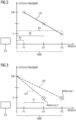
- FIG. 2 a schematic representation for adjusting the light transmittance depending on the distance of the identification transmitter IDG1 from the vehicle F2 is shown according to a first embodiment.
- the access section ZGA is set up to determine the position and in particular the distance of the identification transmitter IDG1 (as an object located outside the vehicle) from the vehicle F2.
- This information about the specific position or distance can now be used by the control device AST to determine the optical properties and, above all, the light transmittance of the panes S1-S4, SF and SH (all panes or specific ones) depending on the distance of the identification transmitter IDG1 from vehicle F2.
- the vehicle F2 is at position O. Furthermore, three exemplary positions for an identification transmitter IDG1 are shown, namely the closest possible position P1 to the vehicle at a distance A1 from the vehicle F2, the position P2 at a distance A2 and finally the position P3 at a distance A3.
- the position P3 should represent the distance up to which the request signals from the vehicle-side antennas reach or up to which a position or distance determination is possible.
- the position P3 thus marks the limit of an approach area ANB, within which the identification transmitter receives the request signals and within which the distance determination is possible.
- the control device AST will control one or more of the disks S1-S4, SF and SH in accordance with the curve LK1 begin. This means that a position or distance determination results in the identification transmitter IDG1 continuing to approach the vehicle F2, for example via the position P2 to the position P1 (as in Figure 1 shown), the control device will control the disks S1-S4, SF and SH accordingly to increase the light transmittance as the distance decreases until the maximum light transmittance LM for driving the vehicle F2 is set at the position P1.
- FIG. 3 a schematic representation for adjusting the light transmittance depending on the distance of the identification transmitter IDG1 from the vehicle F2 is shown according to a second and third embodiment.
- Figure 2 For a basic explanation of the representation of the diagram regarding the X and Y axes see Figure 2 referred.
- a simple distance-dependent control of the disks S1-S4, SF and SH (or only individual disks thereof) is carried out.
- the situation is again assumed that the vehicle F2 has been parked and the windows S1-S4, SF and SH have been brought into a state by the control device AST in which they have a low light transmission, in particular a minimal one Have light transmission LI in order to prevent a view into the passenger compartment FG2 for reasons of theft protection.
- the control device AST in which they have a low light transmission, in particular a minimal one Have light transmission LI in order to prevent a view into the passenger compartment FG2 for reasons of theft protection.
- this "parking state" of the windows in the simplest case there should also be a “driving operating state" of the windows in which they have a higher light transmittance than in the parked state, in particular a maximum light transmittance LM.
- a first exchange of radio signals begins between the vehicle F2 and the identification transmitter IDG1, in which an identification code is also sent from the identification transmitter IDG1 to the vehicle F2 is transmitted. Is it a correct one? Identification code that confirms the affiliation of the identification transmitter IDG1 to the vehicle, which is checked by the access section ZGA, the control device AST will begin to control one or more of the disks S1-S4, SF and SH.
- the control is carried out by the control device AST in such a way that it outputs a control signal to the disks S1-S4, SF and SH so that they assume the "driving operating state" with high light transmission (when the approach range or position P3 is reached).
- This takes into account the case that individual or all panes do not react immediately to the control signal, but have a certain inertia or delay in the change in light transmission.
- activation 1 By activating it early (referred to as "Activation 1" in the drawing), it can be achieved that the change in light transmission begins before the identification transmitter IDG1 arrives on the vehicle F2, and is very likely completed upon arrival or will be completed soon.
- the now dashed curve LK2 is only intended to illustrate the change in light transmission in one or more panes, which occurs with a delay over time if the identification transmitter were to move from position P3 to position P1 (after "Activation 1" has taken place).
- FIG 3 A third embodiment for controlling the one or more disks S1-S4, SF and SH is shown.
- the control device AST should take into account the time interval TT that a window (with a special optically active material) requires in order to come from the "parking state" to the "driving operating state".
- the access section ZGA begins again to determine the position of the identification transmitter. Because of several position measurements, the access section ZGA can not only determine the position of the identification transmitter IDG1, but also its speed of movement. The access section ZGA can thus predict the expected arrival time of the identification transmitter IDG1 at the vehicle FZ.
- control device AST can then activate the one or more panes exactly at a specific time before the arrival of the identification transmitter IDG1 on the vehicle F2, at which the complete change of the Translucency state of the one or more panes is still possible (until the identification transmitter arrives).
- the identification transmitter IDG1 is at position P2 and moves at a predicted speed in the direction of the vehicle FZ to position P1, with a time interval TT being predicted to overcome the distance between position P1 and P2, then the control device AST is activated when the identification transmitter IDG1 is detected Start in position P2 by activating one or more discs ("Activation 2") in order to bring them into the "driving mode".
- the optimal time for changing the light transmission for the panes can be determined by the control device AST.
- the now dashed curve LK3 is only intended to illustrate the change in light transmission in one or more panes, which occurs with a delay over time if the identification transmitter were to move from position P2 to position P1 (after "activation 2" has taken place).
Landscapes
- Engineering & Computer Science (AREA)
- Mechanical Engineering (AREA)
- Physics & Mathematics (AREA)
- Nonlinear Science (AREA)
- General Physics & Mathematics (AREA)
- Optics & Photonics (AREA)
- Multimedia (AREA)
- Theoretical Computer Science (AREA)
- Lock And Its Accessories (AREA)
- Fittings On The Vehicle Exterior For Carrying Loads, And Devices For Holding Or Mounting Articles (AREA)
- Window Of Vehicle (AREA)
- Power-Operated Mechanisms For Wings (AREA)
Description
- Die vorliegende Erfindung betrifft eine Anordnung zum Betreiben einer oder mehrerer am Fahrzeug angebrachter, insbesondere eine Fahrgastzelle begrenzenden Scheiben. Ferner betrifft die Erfindung ein Fahrzeug mit einer entsprechend genannten Anordnung.
- Um einen unbefugten Zutritt zu einem Fahrzeug, insbesondere Kraftfahrzeug zu verhindern, verwenden moderne Zugangsberechtigungssysteme oder Zugangsvorrichtungen in Fahrzeugen elektronische Sicherungssysteme, bei denen zur Authentifizierung des Benutzers eine Datenkommunikation zwischen einer ersten Kommunikationseinrichtung des Fahrzeugs mit einer zweiten Kommunikationseinrichtung in einem mobilen Identifikationsgeber des Benutzers, wie einem Schlüssel oder Schlüsselanhänger, erfolgt, wie z.B. aus der
DE102007023261 A1 bekannt ist. Dabei werden bei einer aktiven Zugangsvorrichtung von dem mobilen Identifikationsgeber Steuersignale sowie ein Identifikationscode, beispielsweise durch Drücken einer entsprechenden Taste durch den Benutzer des mobilen Identifikationsgebers an das Fahrzeug gesendet, woraufhin dieses bei korrektem Identifikationscode entriegelt bzw. verriegelt wird. - Bei einer sog. passiven Zugangsvorrichtung werden zunächst von einer ersten Kommunikationseinrichtung des Fahrzeugs in vorbestimmten regelmäßigen Zeitabständen Funksignale zunächst als Anfragesignale oder Lokalisierungssignale mit einer bestimmten Feldstärke ausgesendet, um zu überprüfen, ob sich ein mobiler Identifikationsgeber in einem Annäherungsbereich um das Fahrzeug befindet. Nähert sich ein mobiler Identifikationsgeber dem Fahrzeug und kann schließlich dessen Anfragesignale empfangen, weil er in den Annährungsbereich eingetreten ist, so wird er auf den Empfang eines Anfragesignals antworten, um einen Authentifizierungsvorgang einzuleiten, und um die Position des mobilen Identifikationsgebers bezüglich des Fahrzeugs bestimmen zu können. Zur Authentifizierung werden Datentelegramme ausgetauscht, in denen letztlich der mobile Identifikationsgeber seinen Identifikationscode dem Fahrzeug übermittelt. Bei erfolgreicher Überprüfung des Identifikationscodes ist es dann möglich, dass ein Benutzer, der sich direkt am Fahrzeug befindet, durch Betätigen eines Türgriffs ein Entriegeln der entsprechenden Fahrzeugtür oder aller Fahrzeugtüren initiiert. Da hier kein aktives Betätigen eines mechanischen oder elektrischen Identifikationsgebers bzw. Schlüssels durch einen Benutzer vorgenommen werden muss, wird diese Art der Zugangsberechtigung auch als passive Zugangsberechtigungsprüfung, und die entsprechenden Zugangsvorrichtungen als passive elektronische Zugangsvorrichtungen bezeichnet.
- Insbesondere bei einer gerade beschriebenen passiven Zugangsvorrichtung kann es nachteilig sein, dass eine Benutzer bzw. Fahrer nicht immer weiß, ob ein ihm zugeordnetes Fahrzeug ihn bei Eintreten in den Annährungsbereich erkannt hat, und ob das Funksignal mit dem Identifikationscode beim Fahrzeug korrekt angekommen ist.
- Somit besteht die Aufgabe der vorliegenden Erfindung, eine Möglichkeit zu schaffen, das Vorhandensein eines Objekts in der Nähe eines Fahrzeugs bzw. eine Annäherung anzuzeigen.
- Gemäß einem ersten Aspekt der Erfindung wird deshalb eine Anordnung zum Betreiben einer oder mehrerer am Fahrzeug angebrachter, insbesondere eine Fahrgastzelle begrenzenden Scheiben, deren optische Eigenschaften durch elektrische Ansteuerung veränderbar sind, geschaffen. Insbesondere handelt es sich bei den Scheiben um transparente Scheiben, die durch elektrische Ansteuerung ihre Lichtdurchlässigkeit als optische Eigenschaft verändern können. Vorteilhafterweise sind die eine oder mehreren transparenten Scheiben derart ausgelegt, dass sie ihre Lichtdurchlässigkeit durch das Anlegen einer elektrischen Spannung verändern. Es ist auch denkbar, dass als optische Eigenschaft einer Scheibe die Farbe durch elektrische Ansteuerung bzw. das Anlegen einer Spannung an die Scheibe veränderbar ist. Zu diesem Zweck der Veränderung der optischen Eigenschaft einer Scheibe weist diese beispielsweise ein elektrisch ansteuerbares optisch aktives Material auf. Die Anordnung hat ferner eine Positionsbestimmungseinrichtung zum Bestimmen der Position eines sich außerhalb des Fahrzeugs befindlichen Objekts, sowie ein Steuergerät, das dafür eingerichtet ist, die eine oder die mehreren Scheiben in Abhängigkeit der von der Bestimmungseinrichtung bestimmten Position anzusteuern. Auf diese Weise kann das Vorhandensein eines Objekts, wie eines Benutzers bzw. Fahrers, in der Nähe eines Fahrzeugs bzw. eine Annäherung angezeigt werden. Insbesondere kann das Steuergerät dafür eingerichtet sein, die eine oder die mehreren Scheiben in Abhängigkeit des Abstands zwischen dem Fahrzeug und dem Objekt anzusteuern, um vor allem eine oder mehrere optische Eigenschaften der einen oder mehreren Scheiben in Abhängigkeit des Abstands zu verändern. Auf diese Weise kann insbesondere eine Bewegung eines Objekts, wie eines Fahrers, zum Fahrzeug hin (Annäherung), aber auch eine Bewegung eines Objekts vom Fahrzeug (Weggehen) durch das Fahrzeug angezeigt werden.
- Erfindungsgemäß ist das Steuergerät dafür eingerichtet, die eine oder die mehreren Scheiben derart anzusteuern, dass deren Lichtdurchlässigkeit mit abnehmendem Abstand erhöht wird. Entsprechend ist es auch denkbar, dass die Lichtdurchlässigkeit mit zunehmendem Abstand verringert wird.
- Auf diese Weise wird beispielsweise einem sich dem Fahrzeug nähernden Fahrer (als das Objekt) signalisiert, dass seine Annährung vom Fahrzeug erkannt wird. Außerdem wird bei einer zunehmenden Lichtdurchlässigkeit der einen oder mehreren Scheiben bei abnehmendem Abstand das Fahrzeug gleich in einen fahrbereiten Zustand gebracht, in dem die Scheiben ja eine möglichst gute bzw. hohe Lichtdurchlässigkeit haben sollten, um ein sicheres Fahren zu ermöglichen.
- Gemäß einer weiteren Ausgestaltung des Steuergeräts ist dieses dafür eingerichtet, die Ansteuerung der einen oder mehreren Scheiben ab bzw. unterhalb eines ersten vorbestimmten Abstands des Objekts vom Fahrzeug zu beginnen, insbesondere wieder derart, dass deren Lichtdurchlässigkeit mit abnehmendem Abstand erhöht wird.
- Es ist auch denkbar, dass das Steuergerät derart eingerichtet ist, die Ansteuerung der einen oder mehreren Scheiben in einem Bereich zwischen einem ersten vorbestimmten Abstand und einem zweiten vorbestimmten Abstand zwischen dem Fahrzeug und dem Objekt durchzuführen, wobei der erste vorbestimmte Abstand größer als der zweite vorbestimmte Abstand ist. Insbesondere erfolgt die Ansteuerung durch das Steuergerät derart, dass deren Lichtdurchlässigkeit der einen oder mehreren Scheiben mit abnehmendem Abstand erhöht wird.
- Es ist überdies denkbar, dass das Steuergerät derart eingerichtet ist, dass es bei einem bestimmten Abstand des Objekts zum Fahrzeug eine Ansteuerung bezüglich einer hohen Lichtdurchlässigkeit bzw. Transparenz durchführt, um die eine oder mehreren Scheiben in einen fahrbereiten Zustand zu versetzen. Es wird dabei davon ausgegangen, dass sich die eine oder mehreren Scheiben des Fahrzeugs in einem Ausgangszustand, wie in einem geparkten Zustand und/der einem verriegelten Zustand, befinden, bei dem sie einen Zustand mit geringer Lichtdurchlässigkeit (z.B. einen opaquen Zustand) aufweisen, in dem ein Blick in die Fahrgastzelle verhindert wird. Auch wenn die eine oder mehreren Scheiben auf die Ansteuerung durch das Steuergerät verzögert reagieren sollten (abhängig von einem ansteuerbaren optisch aktiven Material in der einen oder den mehreren Scheiben), und nicht unmittelbar bei Ansteuerung schon die gewünschte Lichtdurchlässigkeit herstellen, kann durch die Ansteuerung der einen oder mehreren Scheiben bereits vor Eintreffen des Objekts am Fahrzeug erreicht werden, dass die eine oder mehreren Scheiben dann schließlich bei Eintreffen des Objekts am Fahrzeug die gewünschte Lichtdurchlässigkeit haben. Wird beispielsweise ein Fahrer eines Fahrzeugs (als das Objekt) in einem Abstand von zehn Metern vom Fahrzeug entfernt erkannt, so kann das Steuergerät bereits bei diesem Abstand die eine oder die mehreren Scheiben ansteuern, insbesondere um sie in einen fahrbereiten Zustand mit hoher Lichtdurchlässigkeit, beispielsweise mit maximaler Lichtdurchlässigkeit zu bringen. Bewegt sich der Fahrer weiter auf das Fahrzeug zu und erreicht schließlich das Fahrzeug, so kann die eine oder die mehreren Scheiben (auch bei einer verzögerten Reaktion des optisch aktiven Materials in den Scheiben) bereits den gewünschten Zustand der Lichtdurchlässigkeit aufweisen, oder insbesondere dann, wenn der Fahrer im Fahrzeug sitzt, um mit diesem loszufahren.
- In diesem Zusammenhang ist es auch denkbar, dass das Steuergerät die Ansteuerung nicht oder nicht ausschließlich bei einem bestimmten Abstand des Objekts zum Fahrzeug beginnt, sondern anhand einer erfassten Bewegung (ausgehend von einer bestimmten Position und Positionsänderung bzw. Geschwindigkeit) des Objekts den Zeitpunkt schätzt, bis das Objekt am Fahrzeug angekommen sein wird. Entsprechend kann das Steuergerät dann bei Berücksichtigung des notwendigen Zeitintervalls für eine durchzuführende Änderung der Lichtdurchlässigkeit der einen oder der mehreren Scheiben, die Ansteuerung der einen oder der mehreren Scheiben derart (frühzeitig) beginnen, dass die durchzuführende Änderung der Lichtdurchlässigkeit der einen oder der mehreren Scheiben abgeschlossen ist, bevor der abgeschätzte Zeitpunkt des Eintreffens des Objekts beim Fahrzeug erreicht ist.
- Gemäß einer Ausgestaltung der Positionsbestimmungseinrichtung umfasst diese einen optischen Sensor, wie eine Kamera, zum Erfassen des sich außerhalb des Fahrzeugs befindlichen Objekts.
- In diesem Zusammenhang kann die Anordnung eine Bildverarbeitungseinrichtung zur Identifizierung des Objekts (Gesichtserkennung) und/oder bestimmter Eigenschaften des Objekts (Bewegung oder Gang des Objekts) aufweisen. Dabei kann die Bildverarbeitungseinrichtung auch Teil des Steuergeräts sein. Insbesondere kann die Bildverarbeitungseinrichtung dafür ausgelegt sein, die Art des Objekts zu erkennen, beispielsweise ob es sich bei dem Objekt um einen Menschen bzw. Person handelt, die sich dem Fahrzeug nähert. Außerdem kann die Bildverarbeitungseinrichtung dafür ausgelegt sein, bestimmte Eigenschaften des Objekts zu erkennen, und kann in diesem Zusammenhang auch ein Gesicht eines Menschen oder bestimmte Bewegungen bzw. auch den Gang eines Menschen erkennen. Das Gesicht oder der Gang des Menschen können dabei auch als ein biometrischer Identifikationscode dienen.
- Gemäß einer Ausgestaltung des Steuergeräts ist dieses derart eingerichtet, die eine oder die mehreren Scheiben nur dann anzusteuern (um optische Eigenschaften, wie die Lichtdurchlässigkeit zu verändern), wenn die Bildverarbeitungseinrichtung ein bestimmtes Objekt, wie einen Menschen und/oder bestimmte Eigenschaften des Objekts, wie ein bestimmtes Gesicht oder einen bestimmten Gang eines Menschen erkannt hat. Auf diese Weise wird verhindert, dass eine ungewolltes Ansteuern der einen oder der mehreren Scheiben geschieht, d.h. ungewollt bei Objekten, die nicht dem Fahrzeug zugeordnet sind. Auf diese Weise kann einerseits Strom im Fahrzeug gespart, und ferner das ansteuerbare optisch aktive Material in den Scheiben geschont werden.
- Gemäß einer Ausgestaltung der Positionsbestimmungseinrichtung umfasst diese ein Funkmodul zum Empfangen von objektseitigen Funksignalen, die auf die Position des Objekts außerhalb des Fahrzeugs hinweisen. Dabei können die objektseitigen Funksignale Positionsdaten des Objekts enthalten, wie beispielsweise Ortsdaten, insbesondere Ortsdaten eines satellitengestützten Ortungssystems (wie GPS (global positioning system)- Daten). Es ist auch denkbar, dass es sich bei den Ortsdaten um gemessene Feldstärkewerte (RSSI (received signal strenght indicator)-Werte von Anfragesignalen handelt, die von einer oder mehreren fahrzeugseitigen Antennen zur Positionsbestimmung des Objekts ausgesendet worden sind.
- Gemäß einer Ausgestaltung des Funkmoduls kann dieses ferner Anfragesignale zum Auslösen der objektseitigen Funksignale aussenden. Beispielsweise können als Anfragesignale Niederfrequente Funksignale (z.B. bei ca. 125 kHz) ausgesendet werden, deren Feldstärke am Ort des Objekts dann zur Positionsbestimmung bestimmt wird, während als objektseitigen Funksignale dann Hochfrequente objektseitige Funksignale (z.B. bei 433 MHz) zurück gesendet werden. Ferner ist es denkbar, zur Positionsbestimmung des Objekts eine Laufzeitmessung der Anfragesignale vom Fahrzeug zum Objekt und dann der objektseitigen Funksignale vom Objekt zum Fahrzeug durchzuführen.
- Es ist dabei denkbar, dass die objektseitigen Funksignale einen Identifizierungscode umfassen. In diesem Zusammenhang kann das Steuergerät derart eingerichtet sein, die eine oder die mehreren Scheiben nur dann anzusteuern, wenn der durch die Funksignale empfangene Identifizierungscode einem vorbestimmten Code entspricht. Auf diese Weise wird wiederum verhindert, dass eine ungewolltes Ansteuern der einen oder der mehreren Scheiben geschieht, d.h. ungewollt bei Objekten, die nicht dem Fahrzeug zugeordnet sind. Dadurch kann einerseits Strom im Fahrzeug gespart, und ferner das ansteuerbare optisch aktive Material in den Scheiben geschont werden.
- Gemäß einem weiteren Aspekt der Erfindung wird eine Zugangsvorrichtung für ein Fahrzeug geschaffen. Diese hat eine oben dargestellte Anordnung oder eine Ausgestaltung hiervon, sowie eine Verriegelungseinrichtung zum Steuern des Verriegelns und/oder Entriegelns einer oder mehrerer Türen eines Fahrzeugs als Reaktion auf das Empfangen eines korrekten Identifikationscode. Bei dem Identifikationscode kann es sich um einen mittels eines objektseitigen Funksignals übertragenen Code handeln, oder aber auch um einen biometrischen Identifikationscode.
- Gemäß einem weiteren Aspekt der Erfindung wird ein Fahrzeug geschaffen, das eine Fahrgastzelle mit einer oder mehreren diese begrenzenden Scheiben aufweist, deren optische Eigenschaften durch elektrische Ansteuerung veränderbar sind. Ferner hat das Fahrzeug eine oben dargestellte Anordnung oder eine Ausgestaltung hiervon zum Betreiben der einen oder mehreren Scheiben.
- Gemäß einem weiteren Aspekt der Erfindung wird ein Verfahren zum Betreiben einer oder mehrerer am Fahrzeug angebrachter, insbesondere eine Fahrgastzelle begrenzende Scheiben, deren optische Eigenschaften durch elektrische Ansteuerung veränderbar sind, geschaffen. Dabei weist das Verfahren folgende Schritte auf. Es wird eine Position eines sich außerhalb des Fahrzeugs befindlichen Objekts bestimmt. Ferner werden die eine oder die mehreren Scheiben in Abhängigkeit der von der Bestimmungseinrichtung bestimmten Position angesteuert.
- Vorteilhafte Ausgestaltungen der Anordnungen sind, soweit auf das Fahrzeug und das Verfahren übertragbar, auch als vorteilhafte Ausgestaltungen des Fahrzeugs und des Verfahrens anzusehen, und umgekehrt.
- Im Folgenden sollen nun beispielhafte Ausführungsformen der vorliegenden Erfindung Bezug nehmend auf die beiliegenden Zeichnungen näher erläutert werden. Es zeigen:
- Figur 1
- eine schematische Darstellung eines Fahrzeugs mit einer Anordnung zum Betreiben einer oder mehrerer am Fahrzeug angebrachter Scheiben gemäß einer Ausführungsform der Erfindung;
- Figuren 2
- ein Diagramm zum Veranschaulichen der Ansteuerung der einen oder mehreren Scheiben in Abhängigkeit der Position bzw. des Abstands zwischen dem Fahrzeug und einem Identifikationsgeber gemäß einer ersten Ausführungsform für die Ansteuerung;
- Figuren 3
- ein Diagramm zum Veranschaulichen der Ansteuerung der einen oder mehreren Scheiben in Abhängigkeit der Position bzw. des Abstands zwischen dem Fahrzeug und einem Identifikationsgeber gemäß einer zweiten und dritten Ausführungsform für die Ansteuerung.
- Es sei zunächst auf
Figur 1 verwiesen, in der eine schematische Darstellung eines Fahrzeugs F2 mit den wesentlichen Komponenten einer Anordnung zum Betreiben einer oder mehrerer am Fahrzeug F2 angebrachter Scheiben gemäß einer Ausführungsform der Erfindung gezeigt ist. Das Fahrzeug F2 hat dabei eine Fahrgastzelle FG2, die von mehreren transparenten Scheiben S1, S2, S3, S4, SH und SF begrenzt sind. Am hinteren Ende des Fahrzeugs ist die Heckscheibe SH vorgesehen, während am vorderen Ende eine Frontscheibe SF vorgesehen ist. Die übrigen Scheiben S1, S2, S3 und S4 sind entsprechenden Fahrzeugtüren FT1, FT2, FT3 und FT4 jeweils zugeordnet. Entsprechend begrenzen auch die genannten Fahrzeugtüren FT1 - FT4 die Fahrgastzelle FG2. Die Fahrzeugtüren umfassen ferner jeweilige ihnen zugeordnete Türschlösser TS1, TS2, TS3 und TS4, die in einen entriegelten Zustand E und einen verriegelten Zustand V durch elektrische Ansteuerung gebracht werden können. - Das Besondere der Scheiben S1, S2, S3, S4, SH und SF besteht darin, dass es sich hierbei um transparente Scheiben handelt, die ein optisch aktives Material aufweisen, das durch elektrische Ansteuerung zwischen Zuständen mit unterschiedlichem Lichtdurchlassverhalten umschaltbar ist. Derartige schaltbare Scheiben oder Verglasungen werden auch als intelligentes Glas bezeichnet, bei dem die Lichtdurchlässigkeit durch das Anlegen einer elektrischen Spannung verändert werden kann. Die Ansteuerung erfolgt dabei über ein Steuergerät STG. Genauer gesagt umfasst das Steuergerät STG eine Ansteuereinrichtung AST, die über Steuerleitungen SLA, SL1, SL4 bzw. SLB, SL2 und SL3 die Scheiben S1, S4 bzw. S2 und S3 elektrisch ansteuern kann, um deren Lichtdurchlassverhalten zu verändern. Es ist hierbei denkbar, dass neben dem zentralen Steuergerät STG auch weitere dezentrale Steuereinheiten vorhanden sind (nicht dargestellt), die den einzelnen Scheiben S1 - S4 zugeordnet sind, um diese gemäß einer Anweisung vom zentralen Steuergerät STG elektrisch anzusteuern bzw. mit einer Spannung zu beaufschlagen (um quasi ein "Mas-ter-Slave"-Prinzip zwischen Steuergerät und den Steuereinheiten zu realisieren).
- Neben der Anordnung zum Betreiben der einen oder mehreren Scheiben S1 bis S4 hat das Fahrzeug F2 ferner eine Zugangsvorrichtung, deren zentrale Steuerkomponente in Form eines Zugangsabschnitts ZGA ebenso in dem Steuergerät STG untergebracht ist. Dies Zugangsvorrichtung wird insbesondere in einem sogenannten passiven Modus betrieben wird, in dem zunächst von einer ersten Kommunikationseinrichtung (den Antennen AA2, AA3) des Fahrzeugs F2 in regelmäßigen Zeitabständen Anfragesignale LF2, LF3 (insbesondere in Form von niederfrequenten Funksignalen) mit einer bestimmten Feldstärke ausgesendet werden, um zu überprüfen, ob sich ein mobiler Identifikationsgeber IDG1 in einem Annäherungsbereich bzw. Erfassungsbereich um das Fahrzeug F2 befindet. Nähert sich ein mobiler Identifikationsgeber dem Fahrzeug, und kann schließlich dessen Anfragesignale empfangen, so wird er auf den Empfang eines Anfragesignals LF2 bzw. LF3 antworten, um einen Authentifizierungsvorgang einzuleiten. Dabei werden Datentelegramme ausgetauscht, in denen letztlich der mobile Identifikationsgeber IDG1 seinen spezifischen Code oder Identifikationscode dem Fahrzeug in einem hochfrequenten Signal RF2 bzw. RF3 übermittelt. Bei erfolgreicher Überprüfung des Authentifizierungscodes (übereinstimmenden Vergleich mit einem gespeicherten Code) ist es dann möglich, dass ein Benutzer, der sich direkt am Fahrzeug befindet, durch Betätigen eines Türgriffs ein Entriegeln der entsprechenden Fahrzeugtür oder aller Fahrzeugtüren initiiert. Da hier kein aktives Betätigen eines mechanischen oder elektrischen Identifikationsgebers durch einen Benutzer vorgenommen werden muss, wird diese Art der Zugangsberechtigung auch als passiver Modus und die entsprechenden Zugangseinrichtungen als passive elektronische Zugangseinrichtungen bezeichnet.
- Bei diesen passiven Zugangseinrichtungen ist es ferner denkbar, dass nicht nur die Anwesenheit, sondern auch die Position des Identifikationsgebers IDG1 mit Bezug zum Fahrzeug ermittelt werden kann. Wie bereits erwähnt, werden die Anfragesignale LF2 und LF3 mit einer vorbestimmten Feldstärke von den Antennen AA2 und AA3 (natürlich auch durch die Antennen AA1 und AA4, wobei aus Gründen der einfachen Darstellung nur auf die Antennen AA2 und AA3 eingegangen wird) ausgesendet. Entsprechend wird am Ort P1 des Identifikationsgebers IDG1 die Empfangsfeldstärke dieser Anfragesignale gemessen und ein entsprechender Empfangsfeldstärkewert (RSSI = received signal strength indicator-Wert) RSSI2 für das Signal LF2 und RSSI3 für das Signal LF3 bestimmt. Diese Empfangsfeldstärkewerte lassen dann einen Rückschluss auf die Entfernung bzw. den Abstand des Identifikationsgebers IDG1 zu den jeweiligen Antennen AA2 und AA3 zu. Gemäß
Figur 1 wird aufgrund der größeren Nähe des Identifikationsgebers IDG1 zur Antenne AA2 der entsprechende Empfangsfeldstärkewert RSSI2 größer als der Empfangsfeldstärkewert RSSI3 sein. Durch die entsprechende Korrelation der beiden Empfangsfeldstärkewerte kann somit auch die Position des Identifikationsgebers IDG1 bestimmt werden. - Es sei nun auf
Figur 2 verwiesen, in der eine schematische Darstellung zur Einstellung der Lichtdurchlässigkeit in Abhängigkeit des Abstands des Identifikationsgebers IDG1 vom Fahrzeug F2 gemäß einer ersten Ausführungsform gezeigt ist. Wie oben bereits erläutert, ist der Zugangsabschnitt ZGA dafür eingerichtet, die Position und insbesondere auch den Abstand des Identifikationsgebers IDG1 (als ein sich außerhalb des Fahrzeugs befindliches Objekts) vom Fahrzeug F2 zu bestimmen. Diese Information der bestimmten Position bzw. des Abstands kann nun von der Ansteuereinrichtung AST verwendet werden, um die optischen Eigenschaften und vor allem die Lichtdurchlässigkeit der Scheiben S1-S4, SF und SH (aller Scheiben oder bestimmter hiervon) in Abhängigkeit des Abstands des Identifikationsgebers IDG1 vom Fahrzeug F2 einzustellen. - In dem Diagramm von
Figur 2 wird davon ausgegangen, dass sich das Fahrzeug F2 an der Position O befindet. Des Weiteren sind drei beispielhafte Positionen für einen den Identifikationsgeber IDG1 dargestellt, nämlich die zum Fahrzeug nächst mögliche Position P1 in einem Abstand A1 vom Fahrzeug F2, die Position P2 in einem Abstand A2 und schließlich die Position P3 in einem Abstand A3. Dabei soll die Position P3 den Abstand repräsentieren, bis zu dem die Anfragesignale der fahrzeugseitigen Antennen reichen bzw. bis zum dem eine Positions- oder Abstandsbestimmung möglich ist. Die Position P3 markiert somit die Grenze eines Annäherungsbereichs ANB, innerhalb dem der Identifikationsgeber die Anfragesignale empfängt und innerhalb die Abstandsbestimmung möglich ist. - Es wird von der Situation ausgegangen, dass das Fahrzeug F2 abgestellt bzw. geparkt wurde, und die Scheiben S1-S4, SF und SH von der Ansteuereinrichtung AST dem in einen Zustand gebracht worden sind, bei dem sie eine geringe Lichtdurchlässigkeit, insbesondere eine minimale Lichtdurchlässigkeit LI haben, um aus Gründen des Diebstahlschutzes keinen Blick in die Fahrgastzelle FG2 zu ermöglichen. Nähert sich ein Benutzer mit dem Identifikationsgeber IDG1 dem Fahrzeug F2 und kommt an der Position P3 an, so beginnt, wie oben detailliert erläutert, ein erster Austausch von Funksignalen zwischen Fahrzeug F2 und Identifikationsgeber IDG1, bei dem auch ein Identifizierungscode vom Identifikationsgeber IDG1 zum Fahrzeug F2 übermittelt wird. Handelt es sich um einen korrekten Identifizierungscode, der die Zugehörigkeit des Identifikationsgebers IDG1 zum Fahrzeug bestätigt, was durch den Zugangsabschnitt ZGA überprüft wird, so wird die Ansteuereinrichtung AST mit der Ansteuerung einer oder mehrerer der Scheiben S1-S4, SF und SH entsprechend der Kurve LK1 beginnen. Das bedeutet, ergibt eine Positions- bzw. Abstandsbestimmung, dass sich der Identifikationsgeber IDG1 weiter dem Fahrzeug F2 nähert, z.B. über die Position P2 zu der Position P1 (wie in
Figur 1 dargestellt), so wird die Ansteuereinrichtung die Scheiben S1-S4, SF und SH entsprechend ansteuern, bei sich verringerndem Abstand die Lichtdurchlässigkeit zu erhöhen, bis an der der Position P1 die maximale Lichtdurchlässigkeit LM für einen Fahrbetrieb des Fahrzeugs F2 eingestellt ist. - Es sei nun auf
Figur 3 verwiesen, in der eine schematische Darstellung zur Einstellung der Lichtdurchlässigkeit in Abhängigkeit des Abstands des Identifikationsgebers IDG1 vom Fahrzeug F2 gemäß einer zweiten und dritten Ausführungsform gezeigt ist. Zur grundsätzlichen Erläuterung der Darstellung des Diagramms bzgl. X- und Y- Achse sei aufFigur 2 verwiesen. - Gemäß der zweiten Ausführungsform wird eine einfache abstandsabhängige Ansteuerung der Scheiben S1-S4, SF und SH (oder nur einzelner Scheiben davon) durchgeführt. Es wird wieder von der Situation ausgegangen, dass das Fahrzeug F2 abgestellt bzw. geparkt wurde, und die Scheiben S1-S4, SF und SH von der Ansteuereinrichtung AST dem in einen Zustand gebracht worden sind, bei dem sie eine geringe Lichtdurchlässigkeit, insbesondere eine minimale Lichtdurchlässigkeit LI haben, um aus Gründen des Diebstahlschutzes keinen Blick in die Fahrgastzelle FG2 zu ermöglichen. Neben diesem "Parkzustand" der Scheiben soll es im einfachsten Fall noch einen "Fahrbetriebszustand" der Scheiben geben, bei dem diese eine höhere Lichtdurchlässigkeit aufweisen als im Parkzustand, insbesondere eine maximale Lichtdurchlässigkeit LM.
- Nähert sich ein Benutzer mit dem Identifikationsgeber IDG1 dem Fahrzeug F2 und kommt an der Position P3 an, so beginnt, wie oben detailliert erläutert, ein erster Austausch von Funksignalen zwischen Fahrzeug F2 und Identifikationsgeber IDG1, bei dem auch ein Identifizierungscode vom Identifikationsgeber IDG1 zum Fahrzeug F2 übermittelt wird. Handelt es sich um einen korrekten Identifizierungscode, der die Zugehörigkeit des Identifikationsgebers IDG1 zum Fahrzeug bestätigt, was durch den Zugangsabschnitt ZGA überprüft wird, so wird die Ansteuereinrichtung AST mit der Ansteuerung von einer oder mehreren der Scheiben S1-S4, SF und SH beginnen. Gemäß der zweiten Ausführungsform erfolgt die Ansteuerung durch die Ansteuereinrichtung AST derart, dass sie ein Ansteuersignal an die Scheiben S1-S4, SF und SH ausgibt, damit diese (bei Erreichen des Annährungsbereichs bzw. der Position P3) den "Fahrbetriebszustand" mit hoher Lichtdurchlässigkeit einnehmen. Es wird hier dem Fall Rechnung getragen, dass einzelne oder alle Scheiben nicht unmittelbar auf das Ansteuersignal reagieren, sondern eine gewissen Trägheit oder Verzögerung bei der Veränderung der Lichtdurchlässigkeit haben. Durch das frühzeitige Aktivieren (in der Zeichnung als "Aktivierung 1" bezeichnet) kann somit erreicht werden, dass die Veränderung der Lichtdurchlässigkeit schon vor Eintreffen des Identifikationsgebers IDG1 am Fahrzeug F2 begonnen wird, und mit hoher Wahrscheinlich bei Eintreffen abgeschlossen oder bald abgeschlossen ist. Die nun gestrichelte Kurve LK2 soll nur die Veränderung der Lichtdurchlässigkeit in einer oder mehreren Scheiben veranschaulichen, die mit der Zeit verzögert eintritt, wenn sich der Identifikationsgeber von der Position P3 zur Position P1 bewegen würde (nachdem das "Aktivierung 1" erfolgt ist).
- In
Figur 3 ist noch eine dritte Ausführungsform zur Ansteuerung der einen oder mehreren Scheiben S1-S4, SF und SH gezeigt. Hier soll die Ansteuereinrichtung AST das Zeitintervall TT berücksichtigen, das eine Scheibe (mit einem speziellen optisch aktiven Material) benötigt, um von dem "Parkzustand" in den "Fahrbetriebszustand" zu kommen. Nähert sich ein Identifikationsgeber IDG1 wieder dem Fahrzeug F2 und tritt in den Annährungsbereich ANB, so beginnt der Zugangsabschnitt ZGA wieder mit der Positionsbestimmung des Identifikationsgebers. Aufgrund mehrerer Positionsmessungen kann der Zugangsabschnitt ZGA nicht nur die Position des Identifikationsgebers IDG1 bestimmen, sondern auch dessen Bewegungsgeschwindigkeit. Somit kann der Zugangsabschnitt ZGA die voraussichtliche Ankunftszeit des Identifikationsgebers IDG1 am Fahrzeug FZ prognostizieren. Unter Kenntnis der Ankunftszeit sowie des Zeitintervalls zum (vollständigen) Verändern des Lichtdurchlässigkeitszustands einer oder mehrerer Scheiben, kann die Ansteuereinrichtung AST dann die einen oder mehreren Scheiben genau zu einer bestimmten Zeit vor Eintreffen des Identifikationsgebers IDG1 am Fahrzeug F2 aktivieren, bei der die vollständige Veränderung des Lichtdurchlässigkeitszustands der einen oder mehreren Scheiben noch (bis zum Eintreffen des Identifikationsgebers) möglich ist. Befindet sich beispielsweise in derFigur 3 der Identifikationsgeber IDG1 an der Position P2 und bewegt sich mit einer prognostizierten Geschwindigkeit in Richtung Fahrzeug FZ auf die Position P1, wobei zur Überwindung der Strecke zwischen Position P1 und P2 ein Zeitintervall TT prognostiziert wird, dann wird die Ansteuereinrichtung AST bei Erkennen des Identifikationsgebers IDG1 an der Position P2 mit dem Aktivieren der einen oder mehreren Scheiben beginnen ("Aktivierung 2"), um diese in den "Fahrbetriebszustand" zu bringen. Auf diese Weise kann der optimale Zeitpunkt zum Verändern der Lichtdurchlässigkeit für die Scheiben von der Ansteuereinrichtung AST bestimmt werden. Die nun gestrichelte Kurve LK3 soll nur die Veränderung der Lichtdurchlässigkeit in einer oder mehreren Scheiben veranschaulichen, die mit der Zeit verzögert eintritt, wenn sich der Identifikationsgeber von der Position P2 zur Position P1 bewegen würde (nachdem das "Aktivierung 2" erfolgt ist).
Claims (13)
- Anordnung zum Betreiben einer oder mehrerer am Fahrzeug (FZ) angebrachter, insbesondere eine Fahrgastzelle (FGZ) begrenzende Scheiben (S1 - S4, SF, SH), deren optische Eigenschaften durch elektrische Ansteuerung veränderbar sind, wobei die Anordnung folgende Merkmale aufweist:- eine Positionsbestimmungseinrichtung (ZGA) zum Bestimmen der Position (P1-P3) eines sich außerhalb des Fahrzeugs (FZ) befindlichen Objekts (IDG1);- ein Steuergerät (STG, AST), das dafür eingerichtet ist, die eine oder die mehreren Scheiben (S1 - S4, SF, SH) in Abhängigkeit des Abstands (A1, A2, A3) zwischen dem Fahrzeug und dem Objekt (IDG1) anzusteuern,
dadurch gekennzeichnet, dass das Steuergerät ferner derart eingerichtet ist, die eine oder die mehreren Scheiben (S1 - S4, SF, SH) derart anzusteuern, dass deren Lichtdurchlässigkeit mit abnehmendem Abstand erhöht wird, und die Lichtdurchlässigkeit mit zunehmendem Abstand verringert wird. - Anordnung nach Anspruch 1, bei der das Steuergerät derart eingerichtet ist, die Ansteuerung der einen oder mehreren Scheiben unterhalb eines ersten vorbestimmten Abstands (A3) des Objekts (IDG1) vom Fahrzeug (FZ) zu beginnen.
- Anordnung nach Anspruch 1, bei der das Steuergerät derart eingerichtet ist, die Ansteuerung der einen oder mehreren Scheiben (S1 - S4, SF, SH) bei einem bestimmten Abstand des Objekts (IDG1) vom Fahrzeug (FZ) kleiner einem ersten vorbestimmten Abstand (A3) und größer einem zweiten vorbestimmten Abstand (A1) durchzuführen.
- Anordnung nach einem der Ansprüche 1 bis 3, bei der die Positionsbestimmungseinrichtung einen optischen Sensor, wie eine Kamera, zum Erfassen des sich außerhalb des Fahrzeugs befindlichen Objekts umfasst.
- Anordnung nach Anspruch 4, die ferner eine Bildverarbeitungseinrichtung zur Identifizierung des Objekts und/oder bestimmter Eigenschaften des Objekts.
- Anordnung nach Anspruch 5, bei dem das Steuergerät derart eingerichtet ist, die eine oder die mehreren Scheiben (S1 - S4, SF, SH) dann anzusteuern, wenn die Bildverarbeitungseinrichtung ein bestimmtes Objekt und/oder bestimmte Eigenschaften des Objekts erkannt hat.
- Anordnung nach einem der Ansprüche 1 bis 6, bei der die Positionsbestimmungseinrichtung (ZGA) ein Funkmodul (AA3, AA2) zum Empfangen von objektseitigen Funksignalen (RF3, RF2) aufweist, die auf die Position (P1) des Objekts (IDG1) außerhalb des Fahrzeugs (FZ) hinweisen.
- Anordnung nach Anspruch 7, bei der die Funksignale Positionsdaten (RSSI2, RSSI3) des Objekts (IDG1) enthalten.
- Anordnung nach Anspruch 8, bei dem das Funkmodul (AA2, AA3) ferner Anfragesignale (LF2, LF3) zum Auslösen der objektseitigen Funksignale (RF2, RF3) aussendet.
- Anordnung nach einem der Ansprüche 7 bis 9, bei der die objektseitigen Funksignale (RF2, RF3) einen Identifizierungscode umfassen.
- Anordnung nach Anspruch 9, bei dem das Steuergerät (STG) derart eingerichtet ist, die eine oder die mehreren Scheiben (S1 - S4, SF, SH) dann anzusteuern, wenn der durch die objektseitigen Funksignale empfangene Identifizierungscode einem vorbestimmten Code entspricht.
- Fahrzeug (FZ) mit folgenden Merkmalen:- einer Fahrgastzelle (FGZ), die von einer oder mehreren Scheiben (S1 - S4, SF, SH) begrenzt wird,- einer Anordnung nach einem der Ansprüche 1 bis 11 zum Betreiben der einen oder mehreren Scheiben (S1 - S4, SF, SH) .
- Verfahren zum Betreiben einer oder mehrerer am Fahrzeug (FZ) angebrachter, insbesondere eine Fahrgastzelle (FGZ) begrenzende Scheiben (S1 - S4, SF, SH), deren optische Eigenschaften durch elektrische Ansteuerung veränderbar ist, wobei das Verfahren folgende Schritte aufweist:- Bestimmen der Position (P1-P3) eines sich außerhalb des Fahrzeugs (FZ) befindlichen Objekts (IDG1);- Ansteuern der einen oder mehreren Scheiben (S1 - S4, SF, SH) in Abhängigkeit des Abstands (A1, A2, A3) zwischen dem Fahrzeug und dem Objekt (IDG1), dadurch gekennzeichnet, dassdie Ansteuerung der einen oder mehreren Scheiben (S1 - S4, SF, SH) derart erfolgt, dass deren Lichtdurchlässigkeit mit abnehmendem Abstand erhöht wird, und deren Lichtdurchlässigkeit mit zunehmendem Abstand verringert wird.
Applications Claiming Priority (2)
| Application Number | Priority Date | Filing Date | Title |
|---|---|---|---|
| DE102016224750.6A DE102016224750A1 (de) | 2016-12-12 | 2016-12-12 | Anordnung zum Betreiben einer oder mehrerer am Fahrzeug angebrachter Scheiben |
| PCT/EP2017/080482 WO2018108501A1 (de) | 2016-12-12 | 2017-11-27 | Anordnung zum betreiben einer oder mehrerer am fahrzeug angebrachter scheiben |
Publications (2)
| Publication Number | Publication Date |
|---|---|
| EP3551507A1 EP3551507A1 (de) | 2019-10-16 |
| EP3551507B1 true EP3551507B1 (de) | 2023-09-13 |
Family
ID=60515376
Family Applications (1)
| Application Number | Title | Priority Date | Filing Date |
|---|---|---|---|
| EP17807817.6A Active EP3551507B1 (de) | 2016-12-12 | 2017-11-27 | Anordnung zum betreiben einer oder mehrerer am fahrzeug angebrachter scheiben |
Country Status (5)
| Country | Link |
|---|---|
| US (1) | US11584200B2 (de) |
| EP (1) | EP3551507B1 (de) |
| CN (1) | CN110023151A (de) |
| DE (1) | DE102016224750A1 (de) |
| WO (1) | WO2018108501A1 (de) |
Families Citing this family (7)
| Publication number | Priority date | Publication date | Assignee | Title |
|---|---|---|---|---|
| DE102017115816A1 (de) * | 2017-07-13 | 2019-01-17 | Witte Automotive Gmbh | System mit Tür, Türschloss und Funkschlüssel |
| US10783792B1 (en) | 2019-10-22 | 2020-09-22 | Capital One Services, Llc | Systems and methods for automated vehicle tracking for readiness with limited human interaction |
| US10762540B1 (en) | 2019-10-22 | 2020-09-01 | Capital One Services, Llc | Systems and methods for automated trade-in with limited human interaction |
| GB2599089B (en) * | 2020-09-18 | 2023-02-01 | Jaguar Land Rover Ltd | Apparatus and methods for variable tint glazing |
| DE102021200557A1 (de) | 2021-01-21 | 2022-07-21 | Brose Fahrzeugteile Se & Co. Kommanditgesellschaft, Bamberg | Verfahren zum Betrieb einer Zugangsbeschränkungseinheit |
| CN118818826A (zh) * | 2023-04-18 | 2024-10-22 | 京东方科技集团股份有限公司 | 一种控制调光玻璃的方法、装置、车辆及电子设备 |
| CN121650589A (zh) * | 2024-09-11 | 2026-03-13 | 北京京东方技术开发有限公司 | 控制方法、电子设备、车辆及系统 |
Family Cites Families (27)
| Publication number | Priority date | Publication date | Assignee | Title |
|---|---|---|---|---|
| DE19957549C2 (de) * | 1999-11-30 | 2002-04-25 | Siemens Ag | Diebstahlschutzsystem für ein Kraftfahrzeug und Verfahren zum Betreiben eines Diebstahlschutzsystems |
| DE19957536C2 (de) * | 1999-11-30 | 2003-04-03 | Siemens Ag | Diebstahlschutzsystem für ein Kraftfahrzeug und Verfahren zum Betreiben eines Diebstahlschutzsystems |
| US8427276B2 (en) * | 2006-02-24 | 2013-04-23 | Denso International America, Inc. | Apparatus for automatically initiating sequence of vehicle functions |
| US8077011B2 (en) * | 2006-02-24 | 2011-12-13 | Denso International America, Inc. | Apparatus for automatically initiating sequence of vehicle functions |
| US8093987B2 (en) * | 2006-02-24 | 2012-01-10 | Denso International America, Inc. | Vehicle electronic key system |
| JP2007332738A (ja) | 2006-06-19 | 2007-12-27 | Denso Corp | 車載機器遠隔制御システム |
| DE102006030298B3 (de) | 2006-06-30 | 2008-04-10 | Siemens Ag | Verfahren zum Betreiben einer Zugangsanordnung |
| JP5149676B2 (ja) | 2008-04-11 | 2013-02-20 | アイシン精機株式会社 | 異常検出装置 |
| FR2933437A1 (fr) * | 2008-11-18 | 2010-01-08 | Continental Automotive France | Procede et dispositif de deverrouillage automatique de vehicule |
| DE102010010057B4 (de) * | 2010-03-03 | 2012-09-06 | Continental Automotive Gmbh | Verfahren zum Steuern einer Tür eines Fahrzeugs |
| DE102011111600A1 (de) * | 2011-08-25 | 2013-02-28 | Audi Ag | n einer Klappe eines Fahrzeugs und zugehöriges Fahrzeug |
| DE102011083772A1 (de) | 2011-09-29 | 2013-04-04 | Continental Automotive Gmbh | Verfahren zum Steuern einer Beleuchtung eines Fahrzeugs |
| CN202753731U (zh) | 2012-06-29 | 2013-02-27 | 浙江吉利汽车研究院有限公司杭州分公司 | 一种车用电控调光玻璃通透度调节的控制装置 |
| KR20140037705A (ko) * | 2012-09-19 | 2014-03-27 | 현대자동차주식회사 | 송신 무선신호의 출력을 가변 제어하는 차량 리모컨 키와 차량 원격 제어 시스템 및 방법 |
| DE102012222175A1 (de) | 2012-12-04 | 2014-06-18 | Robert Bosch Gmbh | Verfahren und Vorrichtung zum Öffnen einer Tür eines Fahrzeugs |
| JP5871866B2 (ja) * | 2013-08-26 | 2016-03-01 | 本田技研工業株式会社 | スマートエントリシステム |
| US20150251588A1 (en) | 2013-11-21 | 2015-09-10 | Ford Global Technologies, Llc | Privacy window assembly |
| US9950658B2 (en) | 2013-11-21 | 2018-04-24 | Ford Global Technologies, Llc | Privacy window system |
| CN103693012A (zh) | 2013-12-23 | 2014-04-02 | 杭州电子科技大学 | 一种汽车防盗系统 |
| KR20150109753A (ko) | 2014-03-20 | 2015-10-02 | 주식회사 대동 | 자동차 |
| CN204172651U (zh) | 2014-09-09 | 2015-02-25 | 泰州欣祥汽配有限公司 | 电致变色防盗汽车车窗 |
| DE102016108652A1 (de) * | 2015-05-26 | 2016-12-01 | Ford Global Technologies, Llc | Privatsphärenfensterbaugruppe |
| RU2710488C2 (ru) * | 2015-06-19 | 2019-12-26 | ФОРД ГЛОУБАЛ ТЕКНОЛОДЖИЗ, ЭлЭлСи | Система тонированных окон |
| DE102015015736A1 (de) * | 2015-12-01 | 2016-06-09 | Daimler Ag | Vorrichtung zur Steuerung eines Transmissionsgrades einer Scheibe eines Kraftwagens |
| KR102561132B1 (ko) * | 2016-09-21 | 2023-07-28 | 엘지전자 주식회사 | 차량에 구비된 차량 제어 장치 및 차량의 제어방법 |
| US10192125B2 (en) * | 2016-10-20 | 2019-01-29 | Ford Global Technologies, Llc | Vehicle-window-transmittance-control apparatus and method |
| US9886805B1 (en) * | 2016-12-07 | 2018-02-06 | Ford Global Technologies, Llc | Priming vehicle access based on wireless key velocity |
-
2016
- 2016-12-12 DE DE102016224750.6A patent/DE102016224750A1/de not_active Ceased
-
2017
- 2017-11-27 WO PCT/EP2017/080482 patent/WO2018108501A1/de not_active Ceased
- 2017-11-27 CN CN201780074047.4A patent/CN110023151A/zh active Pending
- 2017-11-27 EP EP17807817.6A patent/EP3551507B1/de active Active
- 2017-11-27 US US16/469,048 patent/US11584200B2/en active Active
Also Published As
| Publication number | Publication date |
|---|---|
| US11584200B2 (en) | 2023-02-21 |
| EP3551507A1 (de) | 2019-10-16 |
| DE102016224750A1 (de) | 2018-06-14 |
| CN110023151A (zh) | 2019-07-16 |
| WO2018108501A1 (de) | 2018-06-21 |
| US20200070631A1 (en) | 2020-03-05 |
Similar Documents
| Publication | Publication Date | Title |
|---|---|---|
| EP3551507B1 (de) | Anordnung zum betreiben einer oder mehrerer am fahrzeug angebrachter scheiben | |
| DE102011075853B4 (de) | Innen-/Außen-Feststellung für tragbare Sendeeinrichtung mit geringer Latenz | |
| DE102017204078B4 (de) | Verfahren zum Steuern eines Verschlusselements eines Fahrzeugs | |
| EP2821296B1 (de) | Erfassungsverfahren für betätigungsgesten | |
| EP2821807B1 (de) | Bestimmen einer Position einer einem Fahrzeug zugeordneten Vorrichtung | |
| DE102011088917B4 (de) | Zugangsanordnung im Verfahren zum Betreiben einer derartigen Zugangsanordnung | |
| DE102010010057A1 (de) | Verfahren zum Steuern einer Tür eines Fahrzeugs | |
| DE112015002999T5 (de) | Fahrzeugkommunikationssystem, fahrzeugeigene Einrichtung, portable Einrichtung und Computerprogramm | |
| DE10202330A1 (de) | Schließsystem, insbesondere für ein Kraftfahrzeug | |
| DE102009040395A1 (de) | Verfahren zum Steuern einer Tür eines Fahrzeugs | |
| WO2018095798A1 (de) | Zugangsvorrichtung für ein fahrzeug | |
| DE102016213608A1 (de) | Fahrzeugeigenes Vorrichtungssteuersystem, fahrzeugeigene Steuervorrichtung und tragbare Maschine | |
| DE102014101204A1 (de) | Montagemodul für ein Kraftfahrzeug | |
| DE102017222392A1 (de) | Verfahren und Vorrichtung zum automatischen Öffnen eines Objekts | |
| DE102019216947A1 (de) | Verfahren zum Aktivieren einer fernsteuerbaren Funktion eines Kraftfahrzeugs mittels eines mobilen Steuergeräts sowie System zum Durchführen eines derartigen Verfahrens | |
| EP3861536B1 (de) | Zugangssystem für ein fahrzeug, verfahren für ein zugangssystem, computerprogrammprodukt und computerlesbares medium | |
| DE102012020640B4 (de) | Verfahren und Vorrichtung zur Bestimmung eines Abstands und zur Betätigung eines Schließelements eines Fahrzeugs | |
| DE102015215679A1 (de) | Anordnung zum Überwachen der autonomen Fahrt eines Fahrzeugs | |
| DE102014001321B4 (de) | Verfahren zum Betrieb mindestens eines Bedienelements für eine Fahrzeugtür eines Kraftfahrzeugs und Kraftfahrzeug | |
| WO2017108660A1 (de) | Verfahren zur freigabe einer oder mehrerer funktionen in einem fahrzeug | |
| DE102015003888B4 (de) | Verfahren zum Betreiben eines autonomen Kraftfahrzeugs und Kraftfahrzeug | |
| EP3774456B1 (de) | Anordnung für ein fahrzeug und vefahren | |
| DE102005017458A1 (de) | Schließsystem, insbesondere für ein Kraftfahrzeug | |
| WO2017108239A1 (de) | Verfahren zum betreiben eines fahrzeugzugangssystems | |
| DE19844867B4 (de) | Vorrichtung für Kraftfahrzeuge zur Benutzeridentifikation |
Legal Events
| Date | Code | Title | Description |
|---|---|---|---|
| STAA | Information on the status of an ep patent application or granted ep patent |
Free format text: STATUS: UNKNOWN |
|
| STAA | Information on the status of an ep patent application or granted ep patent |
Free format text: STATUS: THE INTERNATIONAL PUBLICATION HAS BEEN MADE |
|
| PUAI | Public reference made under article 153(3) epc to a published international application that has entered the european phase |
Free format text: ORIGINAL CODE: 0009012 |
|
| STAA | Information on the status of an ep patent application or granted ep patent |
Free format text: STATUS: REQUEST FOR EXAMINATION WAS MADE |
|
| 17P | Request for examination filed |
Effective date: 20190522 |
|
| AK | Designated contracting states |
Kind code of ref document: A1 Designated state(s): AL AT BE BG CH CY CZ DE DK EE ES FI FR GB GR HR HU IE IS IT LI LT LU LV MC MK MT NL NO PL PT RO RS SE SI SK SM TR |
|
| AX | Request for extension of the european patent |
Extension state: BA ME |
|
| DAV | Request for validation of the european patent (deleted) | ||
| DAX | Request for extension of the european patent (deleted) | ||
| RAP1 | Party data changed (applicant data changed or rights of an application transferred) |
Owner name: CONTINENTAL AUTOMOTIVE TECHNOLOGIES GMBH |
|
| GRAP | Despatch of communication of intention to grant a patent |
Free format text: ORIGINAL CODE: EPIDOSNIGR1 |
|
| STAA | Information on the status of an ep patent application or granted ep patent |
Free format text: STATUS: GRANT OF PATENT IS INTENDED |
|
| INTG | Intention to grant announced |
Effective date: 20230421 |
|
| GRAS | Grant fee paid |
Free format text: ORIGINAL CODE: EPIDOSNIGR3 |
|
| GRAA | (expected) grant |
Free format text: ORIGINAL CODE: 0009210 |
|
| STAA | Information on the status of an ep patent application or granted ep patent |
Free format text: STATUS: THE PATENT HAS BEEN GRANTED |
|
| AK | Designated contracting states |
Kind code of ref document: B1 Designated state(s): AL AT BE BG CH CY CZ DE DK EE ES FI FR GB GR HR HU IE IS IT LI LT LU LV MC MK MT NL NO PL PT RO RS SE SI SK SM TR |
|
| REG | Reference to a national code |
Ref country code: GB Ref legal event code: FG4D Free format text: NOT ENGLISH |
|
| REG | Reference to a national code |
Ref country code: CH Ref legal event code: EP |
|
| REG | Reference to a national code |
Ref country code: DE Ref legal event code: R096 Ref document number: 502017015382 Country of ref document: DE |
|
| REG | Reference to a national code |
Ref country code: IE Ref legal event code: FG4D Free format text: LANGUAGE OF EP DOCUMENT: GERMAN |
|
| REG | Reference to a national code |
Ref country code: LT Ref legal event code: MG9D |
|
| REG | Reference to a national code |
Ref country code: NL Ref legal event code: MP Effective date: 20230913 |
|
| PG25 | Lapsed in a contracting state [announced via postgrant information from national office to epo] |
Ref country code: GR Free format text: LAPSE BECAUSE OF FAILURE TO SUBMIT A TRANSLATION OF THE DESCRIPTION OR TO PAY THE FEE WITHIN THE PRESCRIBED TIME-LIMIT Effective date: 20231214 |
|
| PG25 | Lapsed in a contracting state [announced via postgrant information from national office to epo] |
Ref country code: SE Free format text: LAPSE BECAUSE OF FAILURE TO SUBMIT A TRANSLATION OF THE DESCRIPTION OR TO PAY THE FEE WITHIN THE PRESCRIBED TIME-LIMIT Effective date: 20230913 Ref country code: RS Free format text: LAPSE BECAUSE OF FAILURE TO SUBMIT A TRANSLATION OF THE DESCRIPTION OR TO PAY THE FEE WITHIN THE PRESCRIBED TIME-LIMIT Effective date: 20230913 Ref country code: NO Free format text: LAPSE BECAUSE OF FAILURE TO SUBMIT A TRANSLATION OF THE DESCRIPTION OR TO PAY THE FEE WITHIN THE PRESCRIBED TIME-LIMIT Effective date: 20231213 Ref country code: LV Free format text: LAPSE BECAUSE OF FAILURE TO SUBMIT A TRANSLATION OF THE DESCRIPTION OR TO PAY THE FEE WITHIN THE PRESCRIBED TIME-LIMIT Effective date: 20230913 Ref country code: LT Free format text: LAPSE BECAUSE OF FAILURE TO SUBMIT A TRANSLATION OF THE DESCRIPTION OR TO PAY THE FEE WITHIN THE PRESCRIBED TIME-LIMIT Effective date: 20230913 Ref country code: HR Free format text: LAPSE BECAUSE OF FAILURE TO SUBMIT A TRANSLATION OF THE DESCRIPTION OR TO PAY THE FEE WITHIN THE PRESCRIBED TIME-LIMIT Effective date: 20230913 Ref country code: GR Free format text: LAPSE BECAUSE OF FAILURE TO SUBMIT A TRANSLATION OF THE DESCRIPTION OR TO PAY THE FEE WITHIN THE PRESCRIBED TIME-LIMIT Effective date: 20231214 Ref country code: FI Free format text: LAPSE BECAUSE OF FAILURE TO SUBMIT A TRANSLATION OF THE DESCRIPTION OR TO PAY THE FEE WITHIN THE PRESCRIBED TIME-LIMIT Effective date: 20230913 |
|
| REG | Reference to a national code |
Ref country code: DE Ref legal event code: R081 Ref document number: 502017015382 Country of ref document: DE Owner name: CONTINENTAL AUTOMOTIVE TECHNOLOGIES GMBH, DE Free format text: FORMER OWNER: CONTINENTAL AUTOMOTIVE TECHNOLOGIES GMBH, 30165 HANNOVER, DE Ref country code: DE Ref legal event code: R081 Ref document number: 502017015382 Country of ref document: DE Owner name: AUMOVIO GERMANY GMBH, DE Free format text: FORMER OWNER: CONTINENTAL AUTOMOTIVE TECHNOLOGIES GMBH, 30165 HANNOVER, DE |
|
| PG25 | Lapsed in a contracting state [announced via postgrant information from national office to epo] |
Ref country code: NL Free format text: LAPSE BECAUSE OF FAILURE TO SUBMIT A TRANSLATION OF THE DESCRIPTION OR TO PAY THE FEE WITHIN THE PRESCRIBED TIME-LIMIT Effective date: 20230913 |
|
| PG25 | Lapsed in a contracting state [announced via postgrant information from national office to epo] |
Ref country code: IS Free format text: LAPSE BECAUSE OF FAILURE TO SUBMIT A TRANSLATION OF THE DESCRIPTION OR TO PAY THE FEE WITHIN THE PRESCRIBED TIME-LIMIT Effective date: 20240113 |
|
| RAP4 | Party data changed (patent owner data changed or rights of a patent transferred) |
Owner name: CONTINENTAL AUTOMOTIVE TECHNOLOGIES GMBH |
|
| PG25 | Lapsed in a contracting state [announced via postgrant information from national office to epo] |
Ref country code: ES Free format text: LAPSE BECAUSE OF FAILURE TO SUBMIT A TRANSLATION OF THE DESCRIPTION OR TO PAY THE FEE WITHIN THE PRESCRIBED TIME-LIMIT Effective date: 20230913 |
|
| PG25 | Lapsed in a contracting state [announced via postgrant information from national office to epo] |
Ref country code: SM Free format text: LAPSE BECAUSE OF FAILURE TO SUBMIT A TRANSLATION OF THE DESCRIPTION OR TO PAY THE FEE WITHIN THE PRESCRIBED TIME-LIMIT Effective date: 20230913 Ref country code: RO Free format text: LAPSE BECAUSE OF FAILURE TO SUBMIT A TRANSLATION OF THE DESCRIPTION OR TO PAY THE FEE WITHIN THE PRESCRIBED TIME-LIMIT Effective date: 20230913 Ref country code: IS Free format text: LAPSE BECAUSE OF FAILURE TO SUBMIT A TRANSLATION OF THE DESCRIPTION OR TO PAY THE FEE WITHIN THE PRESCRIBED TIME-LIMIT Effective date: 20240113 Ref country code: ES Free format text: LAPSE BECAUSE OF FAILURE TO SUBMIT A TRANSLATION OF THE DESCRIPTION OR TO PAY THE FEE WITHIN THE PRESCRIBED TIME-LIMIT Effective date: 20230913 Ref country code: EE Free format text: LAPSE BECAUSE OF FAILURE TO SUBMIT A TRANSLATION OF THE DESCRIPTION OR TO PAY THE FEE WITHIN THE PRESCRIBED TIME-LIMIT Effective date: 20230913 Ref country code: CZ Free format text: LAPSE BECAUSE OF FAILURE TO SUBMIT A TRANSLATION OF THE DESCRIPTION OR TO PAY THE FEE WITHIN THE PRESCRIBED TIME-LIMIT Effective date: 20230913 Ref country code: PT Free format text: LAPSE BECAUSE OF FAILURE TO SUBMIT A TRANSLATION OF THE DESCRIPTION OR TO PAY THE FEE WITHIN THE PRESCRIBED TIME-LIMIT Effective date: 20240115 Ref country code: SK Free format text: LAPSE BECAUSE OF FAILURE TO SUBMIT A TRANSLATION OF THE DESCRIPTION OR TO PAY THE FEE WITHIN THE PRESCRIBED TIME-LIMIT Effective date: 20230913 |
|
| REG | Reference to a national code |
Ref country code: CH Ref legal event code: PK Free format text: DIE PUBLIKATION VOM 27.03.2024 WURDE AM 24.04.2024 IRRTUEMLICHERWEISE ERNEUT PUBLIZIERT. LA PUBLICATION DU 27.03.2024 A ETE REPUBLIEE PAR ERREUR LE 24.04.2024. LA PUBBLICAZIONE DEL 27.03.2024 E STATA ERRONEAMENTE RIPUBBLICATA IL 24.04.2024. |
|
| PG25 | Lapsed in a contracting state [announced via postgrant information from national office to epo] |
Ref country code: PL Free format text: LAPSE BECAUSE OF FAILURE TO SUBMIT A TRANSLATION OF THE DESCRIPTION OR TO PAY THE FEE WITHIN THE PRESCRIBED TIME-LIMIT Effective date: 20230913 Ref country code: IT Free format text: LAPSE BECAUSE OF FAILURE TO SUBMIT A TRANSLATION OF THE DESCRIPTION OR TO PAY THE FEE WITHIN THE PRESCRIBED TIME-LIMIT Effective date: 20230913 |
|
| REG | Reference to a national code |
Ref country code: DE Ref legal event code: R097 Ref document number: 502017015382 Country of ref document: DE |
|
| REG | Reference to a national code |
Ref country code: CH Ref legal event code: PL |
|
| PG25 | Lapsed in a contracting state [announced via postgrant information from national office to epo] |
Ref country code: MC Free format text: LAPSE BECAUSE OF FAILURE TO SUBMIT A TRANSLATION OF THE DESCRIPTION OR TO PAY THE FEE WITHIN THE PRESCRIBED TIME-LIMIT Effective date: 20230913 |
|
| PG25 | Lapsed in a contracting state [announced via postgrant information from national office to epo] |
Ref country code: DK Free format text: LAPSE BECAUSE OF FAILURE TO SUBMIT A TRANSLATION OF THE DESCRIPTION OR TO PAY THE FEE WITHIN THE PRESCRIBED TIME-LIMIT Effective date: 20230913 |
|
| PG25 | Lapsed in a contracting state [announced via postgrant information from national office to epo] |
Ref country code: LU Free format text: LAPSE BECAUSE OF NON-PAYMENT OF DUE FEES Effective date: 20231127 |
|
| PG25 | Lapsed in a contracting state [announced via postgrant information from national office to epo] |
Ref country code: CH Free format text: LAPSE BECAUSE OF NON-PAYMENT OF DUE FEES Effective date: 20231130 |
|
| PLBE | No opposition filed within time limit |
Free format text: ORIGINAL CODE: 0009261 |
|
| STAA | Information on the status of an ep patent application or granted ep patent |
Free format text: STATUS: NO OPPOSITION FILED WITHIN TIME LIMIT |
|
| PG25 | Lapsed in a contracting state [announced via postgrant information from national office to epo] |
Ref country code: MC Free format text: LAPSE BECAUSE OF FAILURE TO SUBMIT A TRANSLATION OF THE DESCRIPTION OR TO PAY THE FEE WITHIN THE PRESCRIBED TIME-LIMIT Effective date: 20230913 Ref country code: LU Free format text: LAPSE BECAUSE OF NON-PAYMENT OF DUE FEES Effective date: 20231127 Ref country code: DK Free format text: LAPSE BECAUSE OF FAILURE TO SUBMIT A TRANSLATION OF THE DESCRIPTION OR TO PAY THE FEE WITHIN THE PRESCRIBED TIME-LIMIT Effective date: 20230913 Ref country code: CH Free format text: LAPSE BECAUSE OF NON-PAYMENT OF DUE FEES Effective date: 20231130 |
|
| REG | Reference to a national code |
Ref country code: BE Ref legal event code: MM Effective date: 20231130 |
|
| 26N | No opposition filed |
Effective date: 20240614 |
|
| REG | Reference to a national code |
Ref country code: IE Ref legal event code: MM4A |
|
| PG25 | Lapsed in a contracting state [announced via postgrant information from national office to epo] |
Ref country code: IE Free format text: LAPSE BECAUSE OF NON-PAYMENT OF DUE FEES Effective date: 20231127 |
|
| PG25 | Lapsed in a contracting state [announced via postgrant information from national office to epo] |
Ref country code: BE Free format text: LAPSE BECAUSE OF NON-PAYMENT OF DUE FEES Effective date: 20231130 |
|
| PG25 | Lapsed in a contracting state [announced via postgrant information from national office to epo] |
Ref country code: SI Free format text: LAPSE BECAUSE OF FAILURE TO SUBMIT A TRANSLATION OF THE DESCRIPTION OR TO PAY THE FEE WITHIN THE PRESCRIBED TIME-LIMIT Effective date: 20230913 |
|
| PG25 | Lapsed in a contracting state [announced via postgrant information from national office to epo] |
Ref country code: SI Free format text: LAPSE BECAUSE OF FAILURE TO SUBMIT A TRANSLATION OF THE DESCRIPTION OR TO PAY THE FEE WITHIN THE PRESCRIBED TIME-LIMIT Effective date: 20230913 Ref country code: IE Free format text: LAPSE BECAUSE OF NON-PAYMENT OF DUE FEES Effective date: 20231127 Ref country code: BE Free format text: LAPSE BECAUSE OF NON-PAYMENT OF DUE FEES Effective date: 20231130 |
|
| PG25 | Lapsed in a contracting state [announced via postgrant information from national office to epo] |
Ref country code: BG Free format text: LAPSE BECAUSE OF FAILURE TO SUBMIT A TRANSLATION OF THE DESCRIPTION OR TO PAY THE FEE WITHIN THE PRESCRIBED TIME-LIMIT Effective date: 20230913 |
|
| PG25 | Lapsed in a contracting state [announced via postgrant information from national office to epo] |
Ref country code: BG Free format text: LAPSE BECAUSE OF FAILURE TO SUBMIT A TRANSLATION OF THE DESCRIPTION OR TO PAY THE FEE WITHIN THE PRESCRIBED TIME-LIMIT Effective date: 20230913 |
|
| REG | Reference to a national code |
Ref country code: AT Ref legal event code: MM01 Ref document number: 1610960 Country of ref document: AT Kind code of ref document: T Effective date: 20231127 |
|
| PG25 | Lapsed in a contracting state [announced via postgrant information from national office to epo] |
Ref country code: AT Free format text: LAPSE BECAUSE OF NON-PAYMENT OF DUE FEES Effective date: 20231127 |
|
| PG25 | Lapsed in a contracting state [announced via postgrant information from national office to epo] |
Ref country code: AT Free format text: LAPSE BECAUSE OF NON-PAYMENT OF DUE FEES Effective date: 20231127 |
|
| PG25 | Lapsed in a contracting state [announced via postgrant information from national office to epo] |
Ref country code: CY Free format text: LAPSE BECAUSE OF FAILURE TO SUBMIT A TRANSLATION OF THE DESCRIPTION OR TO PAY THE FEE WITHIN THE PRESCRIBED TIME-LIMIT; INVALID AB INITIO Effective date: 20171127 |
|
| PG25 | Lapsed in a contracting state [announced via postgrant information from national office to epo] |
Ref country code: HU Free format text: LAPSE BECAUSE OF FAILURE TO SUBMIT A TRANSLATION OF THE DESCRIPTION OR TO PAY THE FEE WITHIN THE PRESCRIBED TIME-LIMIT; INVALID AB INITIO Effective date: 20171127 |
|
| PG25 | Lapsed in a contracting state [announced via postgrant information from national office to epo] |
Ref country code: TR Free format text: LAPSE BECAUSE OF FAILURE TO SUBMIT A TRANSLATION OF THE DESCRIPTION OR TO PAY THE FEE WITHIN THE PRESCRIBED TIME-LIMIT Effective date: 20230913 |
|
| PGFP | Annual fee paid to national office [announced via postgrant information from national office to epo] |
Ref country code: DE Payment date: 20251130 Year of fee payment: 9 |
|
| PGFP | Annual fee paid to national office [announced via postgrant information from national office to epo] |
Ref country code: GB Payment date: 20251125 Year of fee payment: 9 |
|
| PGFP | Annual fee paid to national office [announced via postgrant information from national office to epo] |
Ref country code: FR Payment date: 20251124 Year of fee payment: 9 |
|
| REG | Reference to a national code |
Ref country code: DE Ref legal event code: R081 Ref document number: 502017015382 Country of ref document: DE Owner name: AUMOVIO GERMANY GMBH, DE Free format text: FORMER OWNER: CONTINENTAL AUTOMOTIVE TECHNOLOGIES GMBH, 30175 HANNOVER, DE |