EP3551444B1 - Vorrichtung zum herstellen von pellets - Google Patents
Vorrichtung zum herstellen von pellets Download PDFInfo
- Publication number
- EP3551444B1 EP3551444B1 EP17821830.1A EP17821830A EP3551444B1 EP 3551444 B1 EP3551444 B1 EP 3551444B1 EP 17821830 A EP17821830 A EP 17821830A EP 3551444 B1 EP3551444 B1 EP 3551444B1
- Authority
- EP
- European Patent Office
- Prior art keywords
- inner cylinder
- rotation
- machine frame
- eccentric shaft
- axis
- Prior art date
- Legal status (The legal status is an assumption and is not a legal conclusion. Google has not performed a legal analysis and makes no representation as to the accuracy of the status listed.)
- Active
Links
Images


Classifications
-
- B—PERFORMING OPERATIONS; TRANSPORTING
- B30—PRESSES
- B30B—PRESSES IN GENERAL
- B30B11/00—Presses specially adapted for forming shaped articles from material in particulate or plastic state, e.g. briquetting presses, tabletting presses
- B30B11/20—Roller-and-ring machines, i.e. with roller disposed within a ring and co-operating with the inner surface of the ring
- B30B11/201—Roller-and-ring machines, i.e. with roller disposed within a ring and co-operating with the inner surface of the ring for extruding material
- B30B11/202—Ring constructions
-
- B—PERFORMING OPERATIONS; TRANSPORTING
- B30—PRESSES
- B30B—PRESSES IN GENERAL
- B30B11/00—Presses specially adapted for forming shaped articles from material in particulate or plastic state, e.g. briquetting presses, tabletting presses
- B30B11/20—Roller-and-ring machines, i.e. with roller disposed within a ring and co-operating with the inner surface of the ring
- B30B11/201—Roller-and-ring machines, i.e. with roller disposed within a ring and co-operating with the inner surface of the ring for extruding material
- B30B11/208—Roller constructions; Mounting of the rollers
-
- B—PERFORMING OPERATIONS; TRANSPORTING
- B30—PRESSES
- B30B—PRESSES IN GENERAL
- B30B11/00—Presses specially adapted for forming shaped articles from material in particulate or plastic state, e.g. briquetting presses, tabletting presses
- B30B11/22—Extrusion presses; Dies therefor
- B30B11/228—Extrusion presses; Dies therefor using pressing means, e.g. rollers moving over a perforated die plate
-
- B—PERFORMING OPERATIONS; TRANSPORTING
- B29—WORKING OF PLASTICS; WORKING OF SUBSTANCES IN A PLASTIC STATE IN GENERAL
- B29B—PREPARATION OR PRETREATMENT OF THE MATERIAL TO BE SHAPED; MAKING GRANULES OR PREFORMS; RECOVERY OF PLASTICS OR OTHER CONSTITUENTS OF WASTE MATERIAL CONTAINING PLASTICS
- B29B9/00—Making granules
- B29B9/10—Making granules by moulding the material, i.e. treating it in the molten state
-
- Y—GENERAL TAGGING OF NEW TECHNOLOGICAL DEVELOPMENTS; GENERAL TAGGING OF CROSS-SECTIONAL TECHNOLOGIES SPANNING OVER SEVERAL SECTIONS OF THE IPC; TECHNICAL SUBJECTS COVERED BY FORMER USPC CROSS-REFERENCE ART COLLECTIONS [XRACs] AND DIGESTS
- Y02—TECHNOLOGIES OR APPLICATIONS FOR MITIGATION OR ADAPTATION AGAINST CLIMATE CHANGE
- Y02E—REDUCTION OF GREENHOUSE GAS [GHG] EMISSIONS, RELATED TO ENERGY GENERATION, TRANSMISSION OR DISTRIBUTION
- Y02E50/00—Technologies for the production of fuel of non-fossil origin
- Y02E50/10—Biofuels, e.g. bio-diesel
-
- Y—GENERAL TAGGING OF NEW TECHNOLOGICAL DEVELOPMENTS; GENERAL TAGGING OF CROSS-SECTIONAL TECHNOLOGIES SPANNING OVER SEVERAL SECTIONS OF THE IPC; TECHNICAL SUBJECTS COVERED BY FORMER USPC CROSS-REFERENCE ART COLLECTIONS [XRACs] AND DIGESTS
- Y02—TECHNOLOGIES OR APPLICATIONS FOR MITIGATION OR ADAPTATION AGAINST CLIMATE CHANGE
- Y02E—REDUCTION OF GREENHOUSE GAS [GHG] EMISSIONS, RELATED TO ENERGY GENERATION, TRANSMISSION OR DISTRIBUTION
- Y02E50/00—Technologies for the production of fuel of non-fossil origin
- Y02E50/30—Fuel from waste, e.g. synthetic alcohol or diesel
Definitions
- the invention relates to a device for producing pellets with the features of the preamble of claim 1.
- a juice press which has a machine frame, a hollow outer cylinder mounted therein with a first axis of rotation and an inner cylinder arranged in the outer cylinder with a second axis of rotation.
- a wedge-shaped gap is formed between an inner surface of the outer cylinder and an outer surface of the inner cylinder, and the outer cylinder and the inner cylinder have radial holes for pressing liquid through.
- a swivel arm is arranged on each side next to the inner cylinder, on which the inner cylinder is rotatably mounted.
- Each swivel arm is movably mounted on the machine frame in the area of its two ends, with a bearing of each swivel arm being connected to the machine frame via a connecting element in such a way that a distance between the two bearings of the connecting element can be adjusted.
- a device for producing pellets which enables separate coarse and fine adjustment of the distance between an outer cylinder and the inner cylinders arranged therein.
- the inner cylinders are mounted on axes in a machine frame and the coarse adjustment and the fine adjustment of the distance between the inner cylinders and the outer cylinder is carried out by rotating the eccentric axes and the eccentric hollow shafts mounted on them.
- pelleting Pressing shredded material into pellet form, also known as pelleting, offers numerous advantages, such as increased bulk density, standardized material size and avoiding segregation of different starting materials.
- pellets made from shredded biomass e.g. wood pellets, straw pellets or residual value pellets, have become increasingly popular in recent years. decades and occupy an important place today.
- a device for forming strands from a firing mixture is known from AT 122 169 B known.
- the fuel mixture is introduced into a wedge-shaped gap between a rotating, hollow outer cylinder and a rotating inner cylinder arranged therein.
- the outer cylinder is set in rotation via a shaft and the inner cylinder, which is rotatably mounted between two arms and hangs down from the two arms that are rotatably mounted on the shaft, presses the fuel mixture through radial holes in the outer cylinder in the form of a strand.
- the AT 346 705 B a device for producing pressed pieces from bulk material is described.
- a wedge-shaped gap is formed between a pressing ring and a hollow pressing roller arranged therein, into which the bulk material is introduced.
- the pressing roller is set in rotation, whereby the bulk material is pressed into pressed pieces through radial holes in the pressing ring and the pressing roller.
- the material to be pressed in particular shredded biomass
- the invention is therefore based on the object of providing a device of the type mentioned at the outset, which can be used more flexibly than the devices known from the prior art.
- each swivel arm is movably mounted on the machine frame in the region of its two ends.
- a connecting element is arranged between the first end of each pivot arm and the machine frame, which is pivotally connected to the first end of the pivot arm via a first bearing and pivotally connected to the machine frame via a second bearing.
- the distance between the two bearings can be adjusted manually or automatically, for example by using a threaded rod in the connecting element.
- the distance between the rotation axes of the outer and inner cylinders and thus the gap width can be reduced or increased.
- each swivel arm is mounted on the machine frame at the second end by means of an eccentric shaft. This also allows the distance between the rotation axes of the outer and inner cylinders and thus the gap width to be reduced or increased.
- the eccentric shaft has at least a first section with a first axis of rotation and at least two further sections with a second rotation axis.
- the second rotation axis is parallel to the first rotation axis, ie it is at a distance from it, whereby the other sections are eccentric to the first section.
- the eccentric shaft is rotatably mounted with the first section in the machine frame and with the other sections in a second end of each swivel arm. The gap width can thus be adjusted by turning the eccentric shaft.
- the eccentric shaft can be rotated via a drive.
- a drive Preferably, an electric motor, in particular a three-phase motor, is used, with a gear preferably arranged between the motor and the eccentric shaft.
- the drive can also be carried out manually via a lever or a crank.
- the wedge-shaped gap between the outer cylinder and the inner cylinder has a gap width that can be changed, in particular increased or decreased, by changing the distance between the bearings of the connecting element and/or by rotating the eccentric shaft.
- Means, in particular sensors, can be arranged on the connecting element and/or on the eccentric shaft in order to be able to detect and output the distance between the bearings and/or the angle of rotation of the eccentric shaft.
- both the outer cylinder and the inner cylinder are hollow and have essentially radially aligned holes.
- the inner cylinder is driven by a drive via a gear and the material, in particular the shredded biomass, is introduced into the wedge-shaped tapered gap and pressed through the holes into an interior of the inner cylinder and out of the outer cylinder. The material is thereby compressed and brought into the form of pellets.
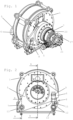
- Fig. 1 shows an apparatus according to the invention for producing pellets, in particular from shredded biomass, in an isometric view.
- a hollow outer cylinder 2 is rotatably mounted in a machine frame 1 and a hollow inner cylinder 3 is arranged in the hollow outer cylinder 2.
- a wedge-shaped gap 4 is formed between an inner surface of the outer cylinder 2 and an outer surface of the inner cylinder 3 ( Fig. 5 ).
- pivot arms 5 are movably mounted on the machine frame 1.
- the inner cylinder 3 is rotatably mounted approximately in the middle area of the pivot arms 5.
- Each swivel arm 5 has two ends 6, 7.
- the first end 6 of the swivel arms 5 is movably connected to the machine frame 1 via a connecting element 8.
- the connecting element 8 is pivotally connected to the first end 6 of the swivel arm 5 via a bearing 9 and pivotally connected to the machine frame 1 via a further bearing 10.
- the second end 7 of the swivel arm 5 is rotatably mounted on the machine frame 1 via an eccentric shaft 13.
- the connecting element 8 has a threaded rod 11 with two nuts, between which a bearing bolt of the other bearing 10 is fixed.
- the nuts 12 By adjusting the nuts 12, the distance between the two bearings 9, 10 and thus the size of the gap 4 can be increased or reduced.
- the eccentric shaft 13 has a first section 23 with a first rotation axis 22, which is rotatably mounted at two points 24 in the machine frame 1, for example in plain bearing bushes.
- Two further sections 25 with a common second rotation axis 26 are rotatably mounted in the second ends 7 of the swivel arms 5, for example also in plain bearing bushes.
- the second axis of rotation 26 is parallel to the first axis of rotation 22, whereby the further sections 25 are eccentric with respect to the first section 23.
- the second ends 7 of the swivel arms 5 are raised or lowered and simultaneously moved sideways.
- the swivel arms 5 are able to carry out the lateral displacements associated with the rotation of the eccentric shaft 13 due to the connecting elements 8 and the connections formed thereby, each of which has two degrees of freedom, between the swivel arms 5 and the machine frame 1.
- the connecting elements 8 can be used to make a pre-setting or a rough adjustment of the gap width
- the eccentric shaft 13 can be used to make a continuous adjustment or a fine adjustment of the gap width.
- the drive 27 is connected to the eccentric shaft 13 via a transmission gear not shown in detail, for example a planetary gear, and a sensor, in particular a rotary encoder, is arranged on the eccentric shaft 13 or in the drive 27, which measures the rotation of the eccentric shaft 13, whereby the width of the gap 4 can be determined.
- a transmission gear not shown in detail, for example a planetary gear
- a sensor in particular a rotary encoder
- the outer cylinder has a first axis of rotation 14 and is mounted on both sides in the machine frame 1 via two cylindrical roller bearings 17.
- the inner cylinder 3 has a second axis of rotation 15 parallel to the first axis of rotation 14 and is rotatably mounted in the pivot arms 5 via a spherical roller bearing 18.
- the wedge-shaped gap 4 which can be adjusted as described above, has in the illustration in Fig. 5 a maximum width at the top and a minimum width at the bottom.
- a clutch 19 connects the inner cylinder 3 with a gear 20, which is Fig. 3 is not shown in detail and can be, for example, a planetary gear.
- the gear 20 is connected via a further clutch 21 to a drive shaft (not shown), e.g. a cardan shaft, which is driven by a main drive (also not shown), whereby the inner cylinder 3 is set in rotation.
- the outer cylinder 2 rotates in the same direction as the inner cylinder due to the frictional forces that arise between the cylinders 2, 3 and the material pressed together between them.
- the outer cylinder 2 is driven and set in rotation by a main drive, whereby the rotation of the inner cylinder 3 is caused due to the frictional forces between the cylinders 2, 3 and the material.
- a main drive whereby the rotation of the inner cylinder 3 is caused due to the frictional forces between the cylinders 2, 3 and the material.
- Another alternative embodiment provides that both the inner cylinder 3 and the outer cylinder 2 are driven.
- the material is introduced into the upper region of the wedge-shaped gap 4 through a filling opening 28 between the cylinders 2, 3 and is moved by the rotation of the same to the lower region of the gap 4 in the region of the minimum width.
- Both the outer cylinder 2 and the inner cylinder 3 have essentially radially aligned holes 16 through which the material, in particular shredded biomass, is pressed and formed into pellets in the region of the minimum width of the gap 4 when the inner cylinder 3 and outer cylinder 2 rotate.
- the pellets formed by the outer cylinder 2 fall out of the device at the bottom, for example directly into a collecting container or onto a conveyor system.
- the pellets formed by the inner cylinder 2 collect inside the inner cylinder 2 and, since the device and the inner cylinder 2 are open on one side, can fall out of the device or be removed from the side.
Landscapes
- Engineering & Computer Science (AREA)
- Mechanical Engineering (AREA)
- Processing Of Solid Wastes (AREA)
- Glanulating (AREA)
- Combined Means For Separation Of Solids (AREA)
- Solid Fuels And Fuel-Associated Substances (AREA)
- Processing And Handling Of Plastics And Other Materials For Molding In General (AREA)
- Fertilizers (AREA)
- Confectionery (AREA)
- Semiconductor Lasers (AREA)
Description
- Die Erfindung betrifft eine Vorrichtung zum Herstellen von Pellets mit den Merkmalen des Oberbegriffs des Anspruches 1.
- Eine derartige Vorrichtung ist aus der
SU 763 154 A SU 958 134 A FR 592 105 A EP 0 594 278 A1 ist eine Vorrichtung zum Herstellen von Pellets bekannt, die eine getrennte Grob- und Feineinstellung des Abstands zwischen einem Außenzylinder und darin angeordneten Innenzylindern ermöglicht. Die Innenzylinder sind über Achsen in einem Maschinenrahmen gelagert und die Grobeinstellung sowie die Feineinstellung des Abstandes zwischen den Innenzylindern und dem Außenzylinder erfolgt über eine Verdrehung der exzentrischen Achsen und darauf gelagerten exzentrischen Hohlwellen. - Das Pressen von zerkleinertem Material in Pellets-Form, das auch als Pelletieren bezeichnet wird, bietet zahlreiche Vorteile, wie beispielsweise eine erhöhte Schüttdichte, eine standardisierte Materialgröße und eine Vermeidung von Entmischung verschiedener Ausgangsmaterialien. In der Aufbereitung von Brennstoff, Futter oder Einstreu haben Pellets aus zerkleinerter Biomasse, z.B. Holzpellets, Strohpellets oder Restwertpellets, in den letzten Jahrzehnten an Bedeutung gewonnen und nehmen heutzutage einen wichtigen Platz ein.
- Eine Vorrichtung zum Formen von Strängen aus einer Brenngutmischung ist aus der
AT 122 169 B - Weiters wird in der
AT 346 705 B - Da das zu pressende Material, insbesondere zerkleinerte Biomasse, eine sehr unterschiedliche Beschaffenheit aufweisen kann, insbesondere was Materialeigenschaften und Größe des zerkleinerten Materials betrifft, ist es nachteilig, wenn die Vorrichtung zum Pressen von Pellets nicht an unterschiedliche Eigenschaften angepasst werden kann.
- Der Erfindung liegt daher die Aufgabe zu Grunde, eine Vorrichtung der eingangs genannten Gattung zur Verfügung zu stellen, welche flexibler einsetzbar ist als die aus dem Stand der Technik bekannten Vorrichtungen.
- Gelöst wird diese Aufgabe erfindungsgemäß mit einer Vorrichtung, welche die Merkmale des Anspruches 1 aufweist.
- Bevorzugte und vorteilhafte Ausführungsformen der Erfindung sind Gegenstand der Unteransprüche.
- Erfindungsgemäß ist vorgesehen, dass jeder Schwenkarm im Bereich seiner beiden Enden beweglich am Maschinenrahmen gelagert ist.
- Dadurch kann die Lage der Drehachsen des Außen- und Innenzylinders zueinander und damit auch die Größe des keilförmigen Spaltes zwischen Außenzylinder und Innenzylinder verändert und die Vorrichtung einfach und effektiv an unterschiedlich beschaffene, zerkleinerte Materialien, insbesondere Biomasse, angepasst werden.
- Bei der Erfindung ist zwischen dem ersten Ende jedes Schwenkarmes und dem Maschinenrahmen ein Verbindungselement angeordnet, das über ein erstes Lager schwenkbar mit dem ersten Ende des Schwenkarmes und über ein zweites Lager schwenkbar mit dem Maschinenrahmen verbunden ist.
- Der Abstand, den die zwei Lager zueinander haben, ist manuell oder automatisch verstellbar, beispielsweise indem das Verbindungselement eine Gewindestange aufweist. Der Abstand der Drehachsen des Außen- und Innenzylinders und damit die Spaltweite kann damit verkleinert oder vergrößert werden.
- Weiters ist bei der Erfindung jeder Schwenkarm an dem zweiten Ende mittels einer Exzenterwelle am Maschinenrahmen gelagert. Auch damit kann der Abstand der Drehachsen des Außen- und Innenzylinders und damit die Spaltweite verkleinert oder vergrößert werden.
- In einer bevorzugten Weiterbildung dieser Ausführungsform weist die Exzenterwelle wenigstens einen ersten Abschnitt mit einer ersten Rotationsachse und wenigstens zwei weitere Abschnitte mit einer zweiten Rotationsachse auf. Die zweite Rotationsachse ist zur ersten Rotationsachse parallel, d.h. hat zu dieser einen Abstand, wodurch die weiteren Abschnitte exzentrisch zum ersten Abschnitt sind. Die Exzenterwelle ist mit dem ersten Abschnitt im Maschinenrahmen und mit den weiteren Abschnitten in jeweils einem zweiten Ende jedes Schwenkarmes drehbar gelagert. Durch Verdrehen der Exzenterwelle kann somit die Spaltweite eingestellt werden.
- Bei dieser Ausführungsform kann weiters vorgesehen sein, dass die Exzenterwelle über einen Antrieb verdrehbar ist. Bevorzugt kommt hierbei ein Elektromotor, insbesondere ein Drehstrommotor, zum Einsatz, wobei zwischen Motor und Exzenterwelle bevorzugt ein Getriebe angeordnet ist. Der Antrieb kann im Rahmen der Erfindung jedoch auch manuell über einen Hebel oder eine Kurbel erfolgen.
- Der keilförmige Spalt zwischen Außenzylinder und Innenzylinder weist eine Spaltweite auf, die durch ein Verändern des Abstandes der Lager des Verbindungselementes und/oder durch ein Verdrehen der Exzenterwelle veränderbar, insbesondere vergrößer- oder verkleinerbar, ist. Am Verbindungselement und/oder an der Exzenterwelle können Mittel, insbesondere Sensoren, angeordnet sein, um den Abstand zwischen den Lagern und/oder den Verdrehwinkel der Exzenterwelle erfassen und ausgeben zu können.
- In einer besonders vorteilhaften Ausführungsform ist vorgesehen, dass sowohl der Außenzylinder als auch der Innenzylinder hohl ausgeführt sind und im Wesentlichen radial ausgerichtete Löcher aufweisen. Vorzugsweise wird der Innenzylinder über ein Getriebe von einem Antrieb angetrieben und das Material, insbesondere die zerkleinerte Biomasse, wird in den sich keilförmig verjüngenden Spalt eingebracht und durch die Löcher in einen Innenraum des Innenzylinders und aus dem Außenzylinder hinausgepresst. Das Material wird dadurch komprimiert und in die Form von Pellets gebracht.
- Weitere Einzelheiten, Merkmale und Vorteile der Erfindung ergeben sich aus der nachstehenden Beschreibung unter Bezugnahme auf die angeschlossenen Zeichnungen, in welchen eine bevorzugte und den Schutzbereich nicht beschränkende Ausführungsform dargestellt ist. Es zeigt:
- Fig. 1
- eine isometrische Ansicht einer erfindungsgemäßen Vorrichtung,
- Fig. 2
- eine Vorderansicht einer erfindungsgemäßen Vorrichtung,
- Fig. 3
- einen Schnitt entlang der Linie A-A in
Fig. 2 , - Fig. 4
- einen Schnitt entlang der Linie B-B in
Fig. 2 und - Fig. 5
- einen Schnitt durch die Vorrichtung normal auf die Schnittebene von
Fig. 3 . -
Fig. 1 zeigt eine erfindungsgemäße Vorrichtung zum Herstellen von Pellets, insbesondere aus zerkleinerter Biomasse, in einer isometrischen Ansicht. - In einem Maschinenrahmen 1 ist ein hohler Außenzylinder 2 drehbar gelagert und in dem hohlen Außenzylinder 2 ist ein hohler Innenzylinder 3 angeordnet. Zwischen einer Innenfläche des Außenzylinders 2 und einer Außenfläche des Innenzylinders 3 ist ein keilförmiger Spalt 4 gebildet (
Fig. 5 ). - Zu beiden Seiten des Innenzylinders 3 sind Schwenkarme 5 am Maschinenrahmen 1 beweglich gelagert. Der Innenzylinder 3 ist etwa im Mittelbereich der Schwenkarme 5 drehbar gelagert.
- Jeder Schwenkarm 5 weist zwei Enden 6, 7 auf. Das erste Ende 6 der Schwenkarme 5 ist über ein Verbindungselement 8 beweglich mit dem Maschinenrahmen 1 verbunden. Das Verbindungselement 8 ist über ein Lager 9 schwenkbar mit dem ersten Ende 6 des Schwenkarms 5 und über ein weiteres Lager 10 schwenkbar mit dem Maschinenrahmen 1 verbunden.
- Das zweite Ende 7 des Schwenkarmes 5 ist drehbar über eine Exzenterwelle 13 am Maschinenrahmen 1 gelagert.
- In der dargestellten Ausführungsform weist das Verbindungselement 8 eine Gewindestange 11 mit zwei Muttern auf, zwischen denen ein Lagerbolzen des anderen Lagers 10 fixiert ist. Durch Verstellen der Muttern 12 kann der Abstand zwischen den beiden Lagern 9, 10 und damit die Größe des Spaltes 4 vergrößert oder verkleinert werden.
- Wie in
Fig. 4 dargestellt, weist die Exzenterwelle 13 einen ersten Abschnitt 23 mit einer ersten Rotationsachse 22 auf, der an zwei Stellen 24 im Maschinenrahmen 1, beispielsweise in Gleitlagerbuchsen, drehbar gelagert ist. Zwei weitere Abschnitte 25 mit einer gemeinsamen zweiten Rotationsachse 26 sind in den zweiten Enden 7 der Schwenkarme 5, beispielsweise ebenfalls in Gleitlagerbuchsen, drehbar gelagert. - Die zweite Rotationsachse 26 liegt parallel zur ersten Rotationsachse 22, wodurch die weiteren Abschnitte 25 gegenüber dem ersten Abschnitt 23 exzentrisch sind.
- Durch ein Verdrehen der Exzenterwelle 13 mit Hilfe eines Antriebes 27, beispielsweise eines Drehstrommotors, werden die zweiten Enden 7 der Schwenkarme 5 angehoben oder abgesenkt und gleichzeitig seitlich verschoben. Durch die Verbindungselemente 8 und die dadurch gebildeten, jeweils zwei Freiheitsgrade aufweisenden Verbindungen zwischen Schwenkarmen 5 und Maschinenrahmen 1 sind die Schwenkarme 5 in der Lage, die mit dem Verdrehen der Exzenterwelle 13 einhergehenden, seitlichen Verschiebungen auszuführen.
- Durch die Verbindungselemente 8 kann beispielsweise eine Voreinstellung bzw. eine Grobeinstellung der Spaltweite und durch die Exzenterwelle 13 eine laufende Anpassung bzw. eine Feineinstellung der Spaltweite vorgenommen werden.
- Der Antrieb 27 ist über ein nicht im Detail dargestelltes Übersetzungsgetriebe, beispielsweise ein Planetengetriebe, mit der Exzenterwelle 13 verbunden und an der Exzenterwelle 13 oder im Antrieb 27 ist ein Sensor, insbesondere ein Drehgeber, angeordnet, der die Verdrehung der Exzenterwelle 13 misst, wodurch die Weite des Spaltes 4 ermittelt werden kann.
- Der Außenzylinder weist eine erste Drehachse 14 auf und ist über zwei Zylinderrollenlager 17 beidseitig im Maschinenrahmen 1 gelagert.
- Der Innenzylinder 3 weist eine zur ersten Drehachse 14 parallele zweite Drehachse 15 auf und ist jeweils über ein Pendelrollenlager 18 in den Schwenkarmen 5 drehbar gelagert.
- Der wie vorstehend beschrieben verstellbare, keilförmige Spalt 4 weist in der Darstellung in
Fig. 5 oben eine maximale und unten eine minimale Breite auf. - Eine Kupplung 19 verbindet den Innenzylinder 3 mit einem Getriebe 20, das in
Fig. 3 nicht im Detail dargestellt ist und beispielsweise ein Planetengetriebe sein kann. Das Getriebe 20 ist über eine weitere Kupplung 21 mit einer nicht dargestellten Antriebswelle, z.B. einer Kardanwelle, verbunden, die von einem ebenfalls nicht dargestellten Hauptantrieb angetrieben wird, wodurch der Innenzylinder 3 in Rotation versetzt wird. Der Außenzylinder 2 rotiert aufgrund der Reibungskräfte, die zwischen den Zylindern 2, 3 und dem dazwischen zusammengepressten Material entstehen, in dieselbe Richtung wie der Innenzylinder. - In einer nicht dargestellten, alternativen Ausführungsform wird der Außenzylinder 2 angetrieben und mit einem Hauptantrieb in Rotation versetzt, wobei aufgrund der Reibkräfte zwischen den Zylindern 2, 3 und dem Material die Rotation des Innenzylinders 3 bewirkt wird. Eine weitere alternative Ausführungsform sieht vor, dass sowohl der Innenzylinder 3 als auch der Außenzylinder 2 angetrieben werden.
- Das Material wird im oberen Bereich des keilförmigen Spaltes 4, durch eine Einfüllöffnung 28 zwischen die Zylinder 2, 3 eingebracht und durch die Rotation derselben zum unteren Bereich des Spaltes 4 im Bereich der minimalen Breite bewegt.
- Sowohl der Außenzylinder 2 als auch der Innenzylinder 3 weisen im Wesentlichen radial ausgerichtete Löcher 16 auf, durch welche das Material, insbesondere zerkleinerte Biomasse, bei rotierendem Innenzylinder 3 und Außenzylinder 2 im Bereich der minimalen Breite des Spaltes 4 gepresst und zu Pellets geformt wird.
- Die vom Außenzylinder 2 gebildeten Pellets fallen unten aus der Vorrichtung heraus, beispielsweise direkt in einen Auffangbehälter oder auf ein Fördersystem. Die vom Innenzylinder 2 gebildeten Pellets sammeln sich im Inneren des Innenzylinders 2 und können, da die Vorrichtung und der Innenzylinder 2 zu einer Seite hin offen sind, seitlich aus der Vorrichtung herausfallen bzw. entnommen werden.
Claims (7)
- Vorrichtung zum Herstellen von Pellets, mit einem Maschinenrahmen (1), einem darin gelagerten, hohlen Außenzylinder (2) mit einer ersten Drehachse (14) und einem im Außenzylinder (2) angeordneten Innenzylinder (3) mit einer zweiten Drehachse (15), wobei zwischen einer Innenfläche des Außenzylinders (2) und einer Außenfläche des Innenzylinders (3) ein keilförmiger Spalt (4) gebildet ist, wobei der Außenzylinder (3) und/oder der Innenzylinder (3) radiale Löcher (16) zum Durchpressen von Material aufweist, wobei beidseitig neben dem Innenzylinder (3) jeweils ein Schwenkarm (5) angeordnet ist, an dem der Innenzylinder (3) drehbar gelagert ist, wobei jeder Schwenkarm (5) im Bereich seiner beiden Enden (6, 7) beweglich am Maschinenrahmen (1) gelagert ist, und wobei jeder Schwenkarm (5) am zweiten Ende (7) mittels einer Exzenterwelle (13) am Maschinenrahmen (1) gelagert ist, gekennzeichnet durch ein Verbindungselement (8), das über ein erstes Lager (9) schwenkbar mit dem ersten Ende (6) des Schwenkarmes (5) und über ein zweites Lager (10) schwenkbar mit dem Maschinenrahmen (1) verbunden ist, und dass ein Abstand zwischen den beiden Lagern (9, 10) des Verbindungselementes (8) einstellbar ist.
- Vorrichtung nach Anspruch 1, dadurch gekennzeichnet, dass die Exzenterwelle (13) wenigstens einen ersten Abschnitt (23) mit einer ersten Rotationsachse (22) und wenigstens zwei weitere Abschnitte (25) mit einer zweiten Rotationsachse (26) aufweist, dass die zweite Rotationsachse (26) zur ersten Rotationsachse (22) parallel ist, und dass die Exzenterwelle (13) mit dem ersten Abschnitt (23) im Maschinenrahmen (1) und mit den weiteren Abschnitten (25) in jeweils einem zweiten Ende (7) jedes Schwenkarmes (5) drehbar gelagert ist.
- Vorrichtung nach Anspruch 1 oder 2, dadurch gekennzeichnet, dass die Exzenterwelle (13) über einen Antrieb (27) verdrehbar ist.
- Vorrichtung nach einem der Ansprüche 1 bis 3, dadurch gekennzeichnet, dass im Bereich der Exzenterwelle (13) ein Mittel zum Messen der Verdrehung der Exzenterwelle (13), insbesondere ein Sensor, vorzugsweise ein Drehgeber, angeordnet ist.
- Vorrichtung nach einem der Ansprüche 1 bis 4, dadurch gekennzeichnet, dass der Innenzylinder (3) über Lager (18), insbesondere Wälzlager, vorzugsweise Pendelrollenlager, an den Schwenkarmen (5) gelagert ist und/oder dass der Außenzylinder (2) beidseitig über Lager (17), insbesondere Wälzlager, vorzugsweise Pendelrollenlager, am Maschinenrahmen (1) gelagert ist.
- Vorrichtung nach einem der Ansprüche 1 bis 5, dadurch gekennzeichnet, dass der Innenzylinder (3) hohl ist.
- Vorrichtung nach einem der Ansprüche 1 bis 6, dadurch gekennzeichnet, dass der Innenzylinder (3) an wenigstens einer Seite über ein Getriebe (20) mit einem Hauptantrieb verbunden ist.
Applications Claiming Priority (2)
| Application Number | Priority Date | Filing Date | Title |
|---|---|---|---|
| ATA51120/2016A AT519102B1 (de) | 2016-12-09 | 2016-12-09 | Vorrichtung zum Herstellen von Pellets |
| PCT/EP2017/081837 WO2018104457A1 (de) | 2016-12-09 | 2017-12-07 | Vorrichtung zum herstellen von pellets |
Publications (3)
| Publication Number | Publication Date |
|---|---|
| EP3551444A1 EP3551444A1 (de) | 2019-10-16 |
| EP3551444B1 true EP3551444B1 (de) | 2024-11-20 |
| EP3551444C0 EP3551444C0 (de) | 2024-11-20 |
Family
ID=60813823
Family Applications (1)
| Application Number | Title | Priority Date | Filing Date |
|---|---|---|---|
| EP17821830.1A Active EP3551444B1 (de) | 2016-12-09 | 2017-12-07 | Vorrichtung zum herstellen von pellets |
Country Status (7)
| Country | Link |
|---|---|
| US (1) | US10843431B2 (de) |
| EP (1) | EP3551444B1 (de) |
| AT (1) | AT519102B1 (de) |
| CA (1) | CA3046409C (de) |
| EA (1) | EA037311B1 (de) |
| MX (1) | MX2019006677A (de) |
| WO (1) | WO2018104457A1 (de) |
Families Citing this family (2)
| Publication number | Priority date | Publication date | Assignee | Title |
|---|---|---|---|---|
| AT521707B1 (de) * | 2018-10-02 | 2023-04-15 | Ludwig Schaider | Vorrichtung zum Herstellen von Pellets |
| AT526792B1 (de) | 2023-09-07 | 2024-07-15 | Schaider Michael | Vorrichtung zum Herstellen von Pellets |
Citations (3)
| Publication number | Priority date | Publication date | Assignee | Title |
|---|---|---|---|---|
| FR592105A (fr) * | 1924-03-20 | 1925-07-28 | Emidecau Sa | Presse à action continue à pression réglable et à contrôle hydraulique |
| EP0594278A1 (de) * | 1992-10-19 | 1994-04-27 | California Pellet Mill Company | Verfahren und Vorrichtung zum Einstellen der Rollen bei einer Pelletpresse |
| WO2016127196A2 (de) * | 2015-02-11 | 2016-08-18 | Josef Schaider Privatstiftung | Pelletiereinrichtung |
Family Cites Families (13)
| Publication number | Priority date | Publication date | Assignee | Title |
|---|---|---|---|---|
| AT122169B (de) | 1927-12-24 | 1931-04-10 | Schwenk Cement U Steinwerke E | Beschickungsvorrichtung für Schacht- und Drehrohröfen zum Brennen von Zement, Kalk u. dgl. |
| US2241546A (en) | 1938-11-12 | 1941-05-13 | Sydney T Evenstad | Pellet machine |
| US2848738A (en) * | 1955-07-13 | 1958-08-26 | Bonnafoux Paul | Pellet mill |
| US3015199A (en) * | 1959-04-08 | 1962-01-02 | Ford Motor Co | Machine for compressing hay into cakes |
| AT346705B (de) * | 1976-01-15 | 1978-11-27 | Kuehtreiber Franz | Presse zur herstellung von presslingen aus schuettgut |
| SU763154A1 (ru) * | 1978-05-03 | 1980-09-15 | Краснодарский политехнический институт | Устройство дл прессовани растительного материала |
| SU958134A1 (ru) * | 1981-03-11 | 1982-09-15 | Краснодарский политехнический институт | Устройство дл уплотнени дисперсного материала |
| SU1006276A1 (ru) * | 1981-06-18 | 1983-03-23 | Краснодарский политехнический институт | Брикетировочный пресс |
| SU1076067A1 (ru) * | 1982-07-14 | 1984-02-29 | Краснодарский политехнический институт | Устройство дл прессовани табачных отходов |
| DD214572A1 (de) * | 1983-04-19 | 1984-10-17 | Anlagenbau Dresden Veb | Stuetzschwinge fuer presswalzen in futtermittelpressen |
| US8974710B2 (en) * | 2011-04-29 | 2015-03-10 | Andritz Ag | Pellet mill having improved construction |
| CH707660A1 (de) * | 2013-02-26 | 2014-08-29 | Bp Recycling Systems Gmbh | Pelletier- oder Granuliervorrichtung. |
| CN204170700U (zh) * | 2014-10-20 | 2015-02-25 | 甘肃农业大学 | 一种快速精确环模制粒机压辊调节机构 |
-
2016
- 2016-12-09 AT ATA51120/2016A patent/AT519102B1/de active
-
2017
- 2017-12-07 US US16/468,214 patent/US10843431B2/en active Active
- 2017-12-07 EA EA201991406A patent/EA037311B1/ru unknown
- 2017-12-07 CA CA3046409A patent/CA3046409C/en active Active
- 2017-12-07 MX MX2019006677A patent/MX2019006677A/es unknown
- 2017-12-07 WO PCT/EP2017/081837 patent/WO2018104457A1/de not_active Ceased
- 2017-12-07 EP EP17821830.1A patent/EP3551444B1/de active Active
Patent Citations (3)
| Publication number | Priority date | Publication date | Assignee | Title |
|---|---|---|---|---|
| FR592105A (fr) * | 1924-03-20 | 1925-07-28 | Emidecau Sa | Presse à action continue à pression réglable et à contrôle hydraulique |
| EP0594278A1 (de) * | 1992-10-19 | 1994-04-27 | California Pellet Mill Company | Verfahren und Vorrichtung zum Einstellen der Rollen bei einer Pelletpresse |
| WO2016127196A2 (de) * | 2015-02-11 | 2016-08-18 | Josef Schaider Privatstiftung | Pelletiereinrichtung |
Also Published As
| Publication number | Publication date |
|---|---|
| EA037311B1 (ru) | 2021-03-10 |
| BR112019011266A2 (pt) | 2019-10-08 |
| EP3551444C0 (de) | 2024-11-20 |
| MX2019006677A (es) | 2019-08-26 |
| AT519102A4 (de) | 2018-04-15 |
| WO2018104457A1 (de) | 2018-06-14 |
| EP3551444A1 (de) | 2019-10-16 |
| US10843431B2 (en) | 2020-11-24 |
| US20190389166A1 (en) | 2019-12-26 |
| CA3046409A1 (en) | 2018-06-14 |
| EA201991406A1 (ru) | 2019-11-29 |
| CA3046409C (en) | 2025-02-04 |
| AT519102B1 (de) | 2018-04-15 |
Similar Documents
| Publication | Publication Date | Title |
|---|---|---|
| EP2065174B1 (de) | Füllvorrichtung für eine Rundlauf-Tablettenpresse | |
| EP3573762B1 (de) | Rührwerksmühle | |
| EP1818102A2 (de) | Walzwerk | |
| EP3551444B1 (de) | Vorrichtung zum herstellen von pellets | |
| EP2105292B1 (de) | Kollerverstellvorrichtung | |
| DE19508093A1 (de) | Fleischwolf | |
| EP3794932A1 (de) | Verschwenkvorrichtung zur gleichmässigen verteilung eines gutes auf einem förder- und reinigungsorgan | |
| AT526792B1 (de) | Vorrichtung zum Herstellen von Pellets | |
| DE102019007192A1 (de) | Vorrichtung zum Zerkleinern von schüttfähigem Aufgabegut sowie Verfahren zum Öffnen einer solchen Vorrichtung | |
| EP1138391A1 (de) | Vorrichtung zum Zerkleinern, Reiben und Dispergieren von fliessfähigem Mahlgut | |
| DE112014001677T5 (de) | Reihentrennvorrichtung, die einen spiralförmigen Heber mit einem veränderlichen Querschnitt hat, und eine Zuckerrohrerntemaschine | |
| EP2885984B1 (de) | Maschine zur Herstellung von stabförmigen Produkten der Tabak verarbeitenden Industrie und Schneidvorrichtung für eine derartige Maschine | |
| DE19529439C1 (de) | Bodenbearbeitungsgerät | |
| EP2139671B1 (de) | Pressschnecke | |
| DE202017001242U1 (de) | Vorrichtung zum Aufbrechen von Kakaoschoten | |
| DE102005052399A1 (de) | Pelletpresse | |
| DE69601164T2 (de) | Vorrichtung und verfahren zur herstellung eines extrudats | |
| EP3400784B1 (de) | Siebeinrichtung für eine erntemaschine sowie erntemaschine | |
| EP3860840B1 (de) | Vorrichtung zum herstellen von pellets | |
| DE902804C (de) | Vorrichtung zum Zerteilen und Quetschen von Stroh und aehnlichen Guetern, insbesondere Gruenfutter | |
| EP4281396B1 (de) | Vorrichtung zum fördern und dosieren von schüttfähigem aufgabegut | |
| DE20016238U1 (de) | Garnkuppler | |
| DE4112341C1 (en) | Appts. for moulding plastic extrusion - includes three or more drivable cylindrical rollers, along funnel mantle surface forming funnel shaped container | |
| DE903779C (de) | Tellerbrecher | |
| DE2550888B2 (de) | Vorrichtung zum Quetschen von Getreidekorn |
Legal Events
| Date | Code | Title | Description |
|---|---|---|---|
| STAA | Information on the status of an ep patent application or granted ep patent |
Free format text: STATUS: UNKNOWN |
|
| STAA | Information on the status of an ep patent application or granted ep patent |
Free format text: STATUS: THE INTERNATIONAL PUBLICATION HAS BEEN MADE |
|
| PUAI | Public reference made under article 153(3) epc to a published international application that has entered the european phase |
Free format text: ORIGINAL CODE: 0009012 |
|
| STAA | Information on the status of an ep patent application or granted ep patent |
Free format text: STATUS: REQUEST FOR EXAMINATION WAS MADE |
|
| 17P | Request for examination filed |
Effective date: 20190708 |
|
| AK | Designated contracting states |
Kind code of ref document: A1 Designated state(s): AL AT BE BG CH CY CZ DE DK EE ES FI FR GB GR HR HU IE IS IT LI LT LU LV MC MK MT NL NO PL PT RO RS SE SI SK SM TR |
|
| AX | Request for extension of the european patent |
Extension state: BA ME |
|
| STAA | Information on the status of an ep patent application or granted ep patent |
Free format text: STATUS: EXAMINATION IS IN PROGRESS |
|
| 17Q | First examination report despatched |
Effective date: 20221130 |
|
| GRAP | Despatch of communication of intention to grant a patent |
Free format text: ORIGINAL CODE: EPIDOSNIGR1 |
|
| STAA | Information on the status of an ep patent application or granted ep patent |
Free format text: STATUS: GRANT OF PATENT IS INTENDED |
|
| INTG | Intention to grant announced |
Effective date: 20240613 |
|
| GRAS | Grant fee paid |
Free format text: ORIGINAL CODE: EPIDOSNIGR3 |
|
| GRAA | (expected) grant |
Free format text: ORIGINAL CODE: 0009210 |
|
| STAA | Information on the status of an ep patent application or granted ep patent |
Free format text: STATUS: THE PATENT HAS BEEN GRANTED |
|
| AK | Designated contracting states |
Kind code of ref document: B1 Designated state(s): AL AT BE BG CH CY CZ DE DK EE ES FI FR GB GR HR HU IE IS IT LI LT LU LV MC MK MT NL NO PL PT RO RS SE SI SK SM TR |
|
| REG | Reference to a national code |
Ref country code: GB Ref legal event code: FG4D Free format text: NOT ENGLISH |
|
| REG | Reference to a national code |
Ref country code: CH Ref legal event code: EP |
|
| REG | Reference to a national code |
Ref country code: DE Ref legal event code: R096 Ref document number: 502017016573 Country of ref document: DE |
|
| REG | Reference to a national code |
Ref country code: IE Ref legal event code: FG4D Free format text: LANGUAGE OF EP DOCUMENT: GERMAN |
|
| U01 | Request for unitary effect filed |
Effective date: 20241120 |
|
| U07 | Unitary effect registered |
Designated state(s): AT BE BG DE DK EE FI FR IT LT LU LV MT NL PT RO SE SI Effective date: 20241127 |
|
| U20 | Renewal fee for the european patent with unitary effect paid |
Year of fee payment: 8 Effective date: 20241227 |
|
| PG25 | Lapsed in a contracting state [announced via postgrant information from national office to epo] |
Ref country code: HR Free format text: LAPSE BECAUSE OF FAILURE TO SUBMIT A TRANSLATION OF THE DESCRIPTION OR TO PAY THE FEE WITHIN THE PRESCRIBED TIME-LIMIT Effective date: 20241120 Ref country code: IS Free format text: LAPSE BECAUSE OF FAILURE TO SUBMIT A TRANSLATION OF THE DESCRIPTION OR TO PAY THE FEE WITHIN THE PRESCRIBED TIME-LIMIT Effective date: 20250320 |
|
| PG25 | Lapsed in a contracting state [announced via postgrant information from national office to epo] |
Ref country code: ES Free format text: LAPSE BECAUSE OF FAILURE TO SUBMIT A TRANSLATION OF THE DESCRIPTION OR TO PAY THE FEE WITHIN THE PRESCRIBED TIME-LIMIT Effective date: 20241120 |
|
| PG25 | Lapsed in a contracting state [announced via postgrant information from national office to epo] |
Ref country code: NO Free format text: LAPSE BECAUSE OF FAILURE TO SUBMIT A TRANSLATION OF THE DESCRIPTION OR TO PAY THE FEE WITHIN THE PRESCRIBED TIME-LIMIT Effective date: 20250220 |
|
| PG25 | Lapsed in a contracting state [announced via postgrant information from national office to epo] |
Ref country code: GR Free format text: LAPSE BECAUSE OF FAILURE TO SUBMIT A TRANSLATION OF THE DESCRIPTION OR TO PAY THE FEE WITHIN THE PRESCRIBED TIME-LIMIT Effective date: 20250221 |
|
| PG25 | Lapsed in a contracting state [announced via postgrant information from national office to epo] |
Ref country code: PL Free format text: LAPSE BECAUSE OF FAILURE TO SUBMIT A TRANSLATION OF THE DESCRIPTION OR TO PAY THE FEE WITHIN THE PRESCRIBED TIME-LIMIT Effective date: 20241120 |
|
| PG25 | Lapsed in a contracting state [announced via postgrant information from national office to epo] |
Ref country code: RS Free format text: LAPSE BECAUSE OF FAILURE TO SUBMIT A TRANSLATION OF THE DESCRIPTION OR TO PAY THE FEE WITHIN THE PRESCRIBED TIME-LIMIT Effective date: 20250220 |
|
| PG25 | Lapsed in a contracting state [announced via postgrant information from national office to epo] |
Ref country code: SM Free format text: LAPSE BECAUSE OF FAILURE TO SUBMIT A TRANSLATION OF THE DESCRIPTION OR TO PAY THE FEE WITHIN THE PRESCRIBED TIME-LIMIT Effective date: 20241120 |
|
| VS25 | Lapsed in a validation state [announced via postgrant information from nat. office to epo] |
Ref country code: MD Free format text: LAPSE BECAUSE OF FAILURE TO SUBMIT A TRANSLATION OF THE DESCRIPTION OR TO PAY THE FEE WITHIN THE PRESCRIBED TIME-LIMIT Effective date: 20241120 |
|
| PG25 | Lapsed in a contracting state [announced via postgrant information from national office to epo] |
Ref country code: SK Free format text: LAPSE BECAUSE OF FAILURE TO SUBMIT A TRANSLATION OF THE DESCRIPTION OR TO PAY THE FEE WITHIN THE PRESCRIBED TIME-LIMIT Effective date: 20241120 |
|
| PG25 | Lapsed in a contracting state [announced via postgrant information from national office to epo] |
Ref country code: CZ Free format text: LAPSE BECAUSE OF FAILURE TO SUBMIT A TRANSLATION OF THE DESCRIPTION OR TO PAY THE FEE WITHIN THE PRESCRIBED TIME-LIMIT Effective date: 20241120 |
|
| REG | Reference to a national code |
Ref country code: CH Ref legal event code: PL |
|
| PG25 | Lapsed in a contracting state [announced via postgrant information from national office to epo] |
Ref country code: MC Free format text: LAPSE BECAUSE OF FAILURE TO SUBMIT A TRANSLATION OF THE DESCRIPTION OR TO PAY THE FEE WITHIN THE PRESCRIBED TIME-LIMIT Effective date: 20241120 |
|
| PLBE | No opposition filed within time limit |
Free format text: ORIGINAL CODE: 0009261 |
|
| STAA | Information on the status of an ep patent application or granted ep patent |
Free format text: STATUS: NO OPPOSITION FILED WITHIN TIME LIMIT |
|
| PG25 | Lapsed in a contracting state [announced via postgrant information from national office to epo] |
Ref country code: CH Free format text: LAPSE BECAUSE OF NON-PAYMENT OF DUE FEES Effective date: 20241231 |
|
| 26N | No opposition filed |
Effective date: 20250821 |
|
| PG25 | Lapsed in a contracting state [announced via postgrant information from national office to epo] |
Ref country code: IE Free format text: LAPSE BECAUSE OF NON-PAYMENT OF DUE FEES Effective date: 20241207 |
|
| GBPC | Gb: european patent ceased through non-payment of renewal fee |
Effective date: 20250220 |
|
| PG25 | Lapsed in a contracting state [announced via postgrant information from national office to epo] |
Ref country code: GB Free format text: LAPSE BECAUSE OF NON-PAYMENT OF DUE FEES Effective date: 20250220 |
|
| U20 | Renewal fee for the european patent with unitary effect paid |
Year of fee payment: 9 Effective date: 20251229 |
|
| VS25 | Lapsed in a validation state [announced via postgrant information from nat. office to epo] |
Ref country code: MA Free format text: FAILURE TO ELECT DOMICILE IN THE NATIONAL COUNTRY Effective date: 20250221 |
|
| PG25 | Lapsed in a contracting state [announced via postgrant information from national office to epo] |
Ref country code: CY Free format text: LAPSE BECAUSE OF FAILURE TO SUBMIT A TRANSLATION OF THE DESCRIPTION OR TO PAY THE FEE WITHIN THE PRESCRIBED TIME-LIMIT; INVALID AB INITIO Effective date: 20171207 |
|
| VS25 | Lapsed in a validation state [announced via postgrant information from nat. office to epo] |
Ref country code: MA Free format text: LAPSE BECAUSE OF FAILURE TO SUBMIT A TRANSLATION OF THE DESCRIPTION OR TO PAY THE FEE WITHIN THE PRESCRIBED TIME-LIMIT Effective date: 20241120 |