EP3551444B1 - Dispositif de fabrication de pellets - Google Patents
Dispositif de fabrication de pellets Download PDFInfo
- Publication number
- EP3551444B1 EP3551444B1 EP17821830.1A EP17821830A EP3551444B1 EP 3551444 B1 EP3551444 B1 EP 3551444B1 EP 17821830 A EP17821830 A EP 17821830A EP 3551444 B1 EP3551444 B1 EP 3551444B1
- Authority
- EP
- European Patent Office
- Prior art keywords
- inner cylinder
- rotation
- machine frame
- eccentric shaft
- axis
- Prior art date
- Legal status (The legal status is an assumption and is not a legal conclusion. Google has not performed a legal analysis and makes no representation as to the accuracy of the status listed.)
- Active
Links
Images


Classifications
-
- B—PERFORMING OPERATIONS; TRANSPORTING
- B30—PRESSES
- B30B—PRESSES IN GENERAL
- B30B11/00—Presses specially adapted for forming shaped articles from material in particulate or plastic state, e.g. briquetting presses, tabletting presses
- B30B11/20—Roller-and-ring machines, i.e. with roller disposed within a ring and co-operating with the inner surface of the ring
- B30B11/201—Roller-and-ring machines, i.e. with roller disposed within a ring and co-operating with the inner surface of the ring for extruding material
- B30B11/202—Ring constructions
-
- B—PERFORMING OPERATIONS; TRANSPORTING
- B30—PRESSES
- B30B—PRESSES IN GENERAL
- B30B11/00—Presses specially adapted for forming shaped articles from material in particulate or plastic state, e.g. briquetting presses, tabletting presses
- B30B11/20—Roller-and-ring machines, i.e. with roller disposed within a ring and co-operating with the inner surface of the ring
- B30B11/201—Roller-and-ring machines, i.e. with roller disposed within a ring and co-operating with the inner surface of the ring for extruding material
- B30B11/208—Roller constructions; Mounting of the rollers
-
- B—PERFORMING OPERATIONS; TRANSPORTING
- B30—PRESSES
- B30B—PRESSES IN GENERAL
- B30B11/00—Presses specially adapted for forming shaped articles from material in particulate or plastic state, e.g. briquetting presses, tabletting presses
- B30B11/22—Extrusion presses; Dies therefor
- B30B11/228—Extrusion presses; Dies therefor using pressing means, e.g. rollers moving over a perforated die plate
-
- B—PERFORMING OPERATIONS; TRANSPORTING
- B29—WORKING OF PLASTICS; WORKING OF SUBSTANCES IN A PLASTIC STATE IN GENERAL
- B29B—PREPARATION OR PRETREATMENT OF THE MATERIAL TO BE SHAPED; MAKING GRANULES OR PREFORMS; RECOVERY OF PLASTICS OR OTHER CONSTITUENTS OF WASTE MATERIAL CONTAINING PLASTICS
- B29B9/00—Making granules
- B29B9/10—Making granules by moulding the material, i.e. treating it in the molten state
-
- Y—GENERAL TAGGING OF NEW TECHNOLOGICAL DEVELOPMENTS; GENERAL TAGGING OF CROSS-SECTIONAL TECHNOLOGIES SPANNING OVER SEVERAL SECTIONS OF THE IPC; TECHNICAL SUBJECTS COVERED BY FORMER USPC CROSS-REFERENCE ART COLLECTIONS [XRACs] AND DIGESTS
- Y02—TECHNOLOGIES OR APPLICATIONS FOR MITIGATION OR ADAPTATION AGAINST CLIMATE CHANGE
- Y02E—REDUCTION OF GREENHOUSE GAS [GHG] EMISSIONS, RELATED TO ENERGY GENERATION, TRANSMISSION OR DISTRIBUTION
- Y02E50/00—Technologies for the production of fuel of non-fossil origin
- Y02E50/10—Biofuels, e.g. bio-diesel
-
- Y—GENERAL TAGGING OF NEW TECHNOLOGICAL DEVELOPMENTS; GENERAL TAGGING OF CROSS-SECTIONAL TECHNOLOGIES SPANNING OVER SEVERAL SECTIONS OF THE IPC; TECHNICAL SUBJECTS COVERED BY FORMER USPC CROSS-REFERENCE ART COLLECTIONS [XRACs] AND DIGESTS
- Y02—TECHNOLOGIES OR APPLICATIONS FOR MITIGATION OR ADAPTATION AGAINST CLIMATE CHANGE
- Y02E—REDUCTION OF GREENHOUSE GAS [GHG] EMISSIONS, RELATED TO ENERGY GENERATION, TRANSMISSION OR DISTRIBUTION
- Y02E50/00—Technologies for the production of fuel of non-fossil origin
- Y02E50/30—Fuel from waste, e.g. synthetic alcohol or diesel
Definitions
- the invention relates to a device for producing pellets with the features of the preamble of claim 1.
- a juice press which has a machine frame, a hollow outer cylinder mounted therein with a first axis of rotation and an inner cylinder arranged in the outer cylinder with a second axis of rotation.
- a wedge-shaped gap is formed between an inner surface of the outer cylinder and an outer surface of the inner cylinder, and the outer cylinder and the inner cylinder have radial holes for pressing liquid through.
- a swivel arm is arranged on each side next to the inner cylinder, on which the inner cylinder is rotatably mounted.
- Each swivel arm is movably mounted on the machine frame in the area of its two ends, with a bearing of each swivel arm being connected to the machine frame via a connecting element in such a way that a distance between the two bearings of the connecting element can be adjusted.
- a device for producing pellets which enables separate coarse and fine adjustment of the distance between an outer cylinder and the inner cylinders arranged therein.
- the inner cylinders are mounted on axes in a machine frame and the coarse adjustment and the fine adjustment of the distance between the inner cylinders and the outer cylinder is carried out by rotating the eccentric axes and the eccentric hollow shafts mounted on them.
- pelleting Pressing shredded material into pellet form, also known as pelleting, offers numerous advantages, such as increased bulk density, standardized material size and avoiding segregation of different starting materials.
- pellets made from shredded biomass e.g. wood pellets, straw pellets or residual value pellets, have become increasingly popular in recent years. decades and occupy an important place today.
- a device for forming strands from a firing mixture is known from AT 122 169 B known.
- the fuel mixture is introduced into a wedge-shaped gap between a rotating, hollow outer cylinder and a rotating inner cylinder arranged therein.
- the outer cylinder is set in rotation via a shaft and the inner cylinder, which is rotatably mounted between two arms and hangs down from the two arms that are rotatably mounted on the shaft, presses the fuel mixture through radial holes in the outer cylinder in the form of a strand.
- the AT 346 705 B a device for producing pressed pieces from bulk material is described.
- a wedge-shaped gap is formed between a pressing ring and a hollow pressing roller arranged therein, into which the bulk material is introduced.
- the pressing roller is set in rotation, whereby the bulk material is pressed into pressed pieces through radial holes in the pressing ring and the pressing roller.
- the material to be pressed in particular shredded biomass
- the invention is therefore based on the object of providing a device of the type mentioned at the outset, which can be used more flexibly than the devices known from the prior art.
- each swivel arm is movably mounted on the machine frame in the region of its two ends.
- a connecting element is arranged between the first end of each pivot arm and the machine frame, which is pivotally connected to the first end of the pivot arm via a first bearing and pivotally connected to the machine frame via a second bearing.
- the distance between the two bearings can be adjusted manually or automatically, for example by using a threaded rod in the connecting element.
- the distance between the rotation axes of the outer and inner cylinders and thus the gap width can be reduced or increased.
- each swivel arm is mounted on the machine frame at the second end by means of an eccentric shaft. This also allows the distance between the rotation axes of the outer and inner cylinders and thus the gap width to be reduced or increased.
- the eccentric shaft has at least a first section with a first axis of rotation and at least two further sections with a second rotation axis.
- the second rotation axis is parallel to the first rotation axis, ie it is at a distance from it, whereby the other sections are eccentric to the first section.
- the eccentric shaft is rotatably mounted with the first section in the machine frame and with the other sections in a second end of each swivel arm. The gap width can thus be adjusted by turning the eccentric shaft.
- the eccentric shaft can be rotated via a drive.
- a drive Preferably, an electric motor, in particular a three-phase motor, is used, with a gear preferably arranged between the motor and the eccentric shaft.
- the drive can also be carried out manually via a lever or a crank.
- the wedge-shaped gap between the outer cylinder and the inner cylinder has a gap width that can be changed, in particular increased or decreased, by changing the distance between the bearings of the connecting element and/or by rotating the eccentric shaft.
- Means, in particular sensors, can be arranged on the connecting element and/or on the eccentric shaft in order to be able to detect and output the distance between the bearings and/or the angle of rotation of the eccentric shaft.
- both the outer cylinder and the inner cylinder are hollow and have essentially radially aligned holes.
- the inner cylinder is driven by a drive via a gear and the material, in particular the shredded biomass, is introduced into the wedge-shaped tapered gap and pressed through the holes into an interior of the inner cylinder and out of the outer cylinder. The material is thereby compressed and brought into the form of pellets.
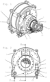
- Fig. 1 shows an apparatus according to the invention for producing pellets, in particular from shredded biomass, in an isometric view.
- a hollow outer cylinder 2 is rotatably mounted in a machine frame 1 and a hollow inner cylinder 3 is arranged in the hollow outer cylinder 2.
- a wedge-shaped gap 4 is formed between an inner surface of the outer cylinder 2 and an outer surface of the inner cylinder 3 ( Fig. 5 ).
- pivot arms 5 are movably mounted on the machine frame 1.
- the inner cylinder 3 is rotatably mounted approximately in the middle area of the pivot arms 5.
- Each swivel arm 5 has two ends 6, 7.
- the first end 6 of the swivel arms 5 is movably connected to the machine frame 1 via a connecting element 8.
- the connecting element 8 is pivotally connected to the first end 6 of the swivel arm 5 via a bearing 9 and pivotally connected to the machine frame 1 via a further bearing 10.
- the second end 7 of the swivel arm 5 is rotatably mounted on the machine frame 1 via an eccentric shaft 13.
- the connecting element 8 has a threaded rod 11 with two nuts, between which a bearing bolt of the other bearing 10 is fixed.
- the nuts 12 By adjusting the nuts 12, the distance between the two bearings 9, 10 and thus the size of the gap 4 can be increased or reduced.
- the eccentric shaft 13 has a first section 23 with a first rotation axis 22, which is rotatably mounted at two points 24 in the machine frame 1, for example in plain bearing bushes.
- Two further sections 25 with a common second rotation axis 26 are rotatably mounted in the second ends 7 of the swivel arms 5, for example also in plain bearing bushes.
- the second axis of rotation 26 is parallel to the first axis of rotation 22, whereby the further sections 25 are eccentric with respect to the first section 23.
- the second ends 7 of the swivel arms 5 are raised or lowered and simultaneously moved sideways.
- the swivel arms 5 are able to carry out the lateral displacements associated with the rotation of the eccentric shaft 13 due to the connecting elements 8 and the connections formed thereby, each of which has two degrees of freedom, between the swivel arms 5 and the machine frame 1.
- the connecting elements 8 can be used to make a pre-setting or a rough adjustment of the gap width
- the eccentric shaft 13 can be used to make a continuous adjustment or a fine adjustment of the gap width.
- the drive 27 is connected to the eccentric shaft 13 via a transmission gear not shown in detail, for example a planetary gear, and a sensor, in particular a rotary encoder, is arranged on the eccentric shaft 13 or in the drive 27, which measures the rotation of the eccentric shaft 13, whereby the width of the gap 4 can be determined.
- a transmission gear not shown in detail, for example a planetary gear
- a sensor in particular a rotary encoder
- the outer cylinder has a first axis of rotation 14 and is mounted on both sides in the machine frame 1 via two cylindrical roller bearings 17.
- the inner cylinder 3 has a second axis of rotation 15 parallel to the first axis of rotation 14 and is rotatably mounted in the pivot arms 5 via a spherical roller bearing 18.
- the wedge-shaped gap 4 which can be adjusted as described above, has in the illustration in Fig. 5 a maximum width at the top and a minimum width at the bottom.
- a clutch 19 connects the inner cylinder 3 with a gear 20, which is Fig. 3 is not shown in detail and can be, for example, a planetary gear.
- the gear 20 is connected via a further clutch 21 to a drive shaft (not shown), e.g. a cardan shaft, which is driven by a main drive (also not shown), whereby the inner cylinder 3 is set in rotation.
- the outer cylinder 2 rotates in the same direction as the inner cylinder due to the frictional forces that arise between the cylinders 2, 3 and the material pressed together between them.
- the outer cylinder 2 is driven and set in rotation by a main drive, whereby the rotation of the inner cylinder 3 is caused due to the frictional forces between the cylinders 2, 3 and the material.
- a main drive whereby the rotation of the inner cylinder 3 is caused due to the frictional forces between the cylinders 2, 3 and the material.
- Another alternative embodiment provides that both the inner cylinder 3 and the outer cylinder 2 are driven.
- the material is introduced into the upper region of the wedge-shaped gap 4 through a filling opening 28 between the cylinders 2, 3 and is moved by the rotation of the same to the lower region of the gap 4 in the region of the minimum width.
- Both the outer cylinder 2 and the inner cylinder 3 have essentially radially aligned holes 16 through which the material, in particular shredded biomass, is pressed and formed into pellets in the region of the minimum width of the gap 4 when the inner cylinder 3 and outer cylinder 2 rotate.
- the pellets formed by the outer cylinder 2 fall out of the device at the bottom, for example directly into a collecting container or onto a conveyor system.
- the pellets formed by the inner cylinder 2 collect inside the inner cylinder 2 and, since the device and the inner cylinder 2 are open on one side, can fall out of the device or be removed from the side.
Landscapes
- Engineering & Computer Science (AREA)
- Mechanical Engineering (AREA)
- Processing Of Solid Wastes (AREA)
- Glanulating (AREA)
- Fertilizers (AREA)
- Confectionery (AREA)
- Combined Means For Separation Of Solids (AREA)
- Solid Fuels And Fuel-Associated Substances (AREA)
- Semiconductor Lasers (AREA)
- Processing And Handling Of Plastics And Other Materials For Molding In General (AREA)
Claims (7)
- Dispositif pour la fabrication de pellets, avec un bâti de machine (1), un cylindre extérieur creux (2) logé dans celui-ci avec un premier axe de rotation (14) et un cylindre intérieur (3) disposé dans le cylindre extérieur (2) avec un deuxième axe de rotation (15), une fente (4) en forme de coin étant formée entre une surface intérieure du cylindre extérieur (2) et une surface extérieure du cylindre intérieur (3), le cylindre extérieur (3) et/ou le cylindre intérieur (3) présentant des trous radiaux (16) pour le pressage de matériau, un bras pivotant (5) étant respectivement disposé des deux côtés à côté du cylindre intérieur (3), sur lequel le cylindre intérieur (3) est monté à rotation, chaque bras pivotant (5) étant monté mobile sur le bâti de machine (1) dans la zone de ses deux extrémités (6, 7), et chaque bras pivotant (5) étant monté sur le bâti de machine (1) à la deuxième extrémité (7) au moyen d'un arbre excentrique (13), caractérisé par un élément de liaison (8) qui est relié de manière pivotante à la première extrémité (6) du bras pivotant (5) par un premier palier (9) et de manière pivotante au bâti de machine (1) par un deuxième palier (10), et en ce qu'une distance entre les deux paliers (9, 10) de l'élément de liaison (8) est réglable.
- Dispositif selon la revendication 1, caractérisé en ce que l'arbre excentrique (13) présente au moins une première section (23) avec un premier axe de rotation (22) et au moins deux autres sections (25) avec un deuxième axe de rotation (26), en ce que le deuxième axe de rotation (26) est parallèle au premier axe de rotation (22), et en ce que l'arbre excentrique (13) est logé de manière rotative avec la première section (23) dans le bâti de machine (1) et avec les autres sections (25) dans respectivement une deuxième extrémité (7) de chaque bras pivotant (5).
- Dispositif selon la revendication 1 ou 2, caractérisé en ce que l'arbre excentrique (13) peut être mis en rotation par un entraînement (27).
- Dispositif selon l'une des revendications 1 à 3, caractérisé en ce qu'un moyen de mesure de la rotation de l'arbre excentrique (13), notamment un capteur, de préférence un capteur de rotation, est disposé dans la zone de l'arbre excentrique (13).
- Dispositif selon l'une des revendications 1 à 4, caractérisé en ce que le cylindre intérieur (3) est monté sur les bras pivotants (5) par l'intermédiaire de paliers (18), notamment de roulements, de préférence de roulements à rotule sur rouleaux, et/ou en ce que le cylindre extérieur (2) est monté des deux côtés sur le bâti de la machine (1) par l'intermédiaire de paliers (17), notamment de roulements, de préférence de roulements à rotule sur rouleaux.
- Dispositif selon l'une des revendications 1 à 5, caractérisé en ce que le cylindre intérieur (3) est creux.
- Dispositif selon l'une des revendications 1 à 6, caractérisé en ce que le cylindre intérieur (3) est relié sur au moins un côté à un entraînement principal par l'intermédiaire d'un engrenage (20).
Applications Claiming Priority (2)
| Application Number | Priority Date | Filing Date | Title |
|---|---|---|---|
| ATA51120/2016A AT519102B1 (de) | 2016-12-09 | 2016-12-09 | Vorrichtung zum Herstellen von Pellets |
| PCT/EP2017/081837 WO2018104457A1 (fr) | 2016-12-09 | 2017-12-07 | Dispositif de fabrication de pellets |
Publications (3)
| Publication Number | Publication Date |
|---|---|
| EP3551444A1 EP3551444A1 (fr) | 2019-10-16 |
| EP3551444B1 true EP3551444B1 (fr) | 2024-11-20 |
| EP3551444C0 EP3551444C0 (fr) | 2024-11-20 |
Family
ID=60813823
Family Applications (1)
| Application Number | Title | Priority Date | Filing Date |
|---|---|---|---|
| EP17821830.1A Active EP3551444B1 (fr) | 2016-12-09 | 2017-12-07 | Dispositif de fabrication de pellets |
Country Status (7)
| Country | Link |
|---|---|
| US (1) | US10843431B2 (fr) |
| EP (1) | EP3551444B1 (fr) |
| AT (1) | AT519102B1 (fr) |
| CA (1) | CA3046409C (fr) |
| EA (1) | EA037311B1 (fr) |
| MX (1) | MX2019006677A (fr) |
| WO (1) | WO2018104457A1 (fr) |
Families Citing this family (2)
| Publication number | Priority date | Publication date | Assignee | Title |
|---|---|---|---|---|
| AT521707B1 (de) * | 2018-10-02 | 2023-04-15 | Ludwig Schaider | Vorrichtung zum Herstellen von Pellets |
| AT526792B1 (de) | 2023-09-07 | 2024-07-15 | Schaider Michael | Vorrichtung zum Herstellen von Pellets |
Citations (3)
| Publication number | Priority date | Publication date | Assignee | Title |
|---|---|---|---|---|
| FR592105A (fr) * | 1924-03-20 | 1925-07-28 | Emidecau Sa | Presse à action continue à pression réglable et à contrôle hydraulique |
| EP0594278A1 (fr) * | 1992-10-19 | 1994-04-27 | California Pellet Mill Company | Dispositif et méthode d'ajustement des rouleaux dans une presse à extruder des granulés |
| WO2016127196A2 (fr) * | 2015-02-11 | 2016-08-18 | Josef Schaider Privatstiftung | Appareil de granulation |
Family Cites Families (13)
| Publication number | Priority date | Publication date | Assignee | Title |
|---|---|---|---|---|
| AT122169B (de) | 1927-12-24 | 1931-04-10 | Schwenk Cement U Steinwerke E | Beschickungsvorrichtung für Schacht- und Drehrohröfen zum Brennen von Zement, Kalk u. dgl. |
| US2241546A (en) * | 1938-11-12 | 1941-05-13 | Sydney T Evenstad | Pellet machine |
| US2848738A (en) * | 1955-07-13 | 1958-08-26 | Bonnafoux Paul | Pellet mill |
| US3015199A (en) * | 1959-04-08 | 1962-01-02 | Ford Motor Co | Machine for compressing hay into cakes |
| AT346705B (de) * | 1976-01-15 | 1978-11-27 | Kuehtreiber Franz | Presse zur herstellung von presslingen aus schuettgut |
| SU763154A1 (ru) * | 1978-05-03 | 1980-09-15 | Краснодарский политехнический институт | Устройство дл прессовани растительного материала |
| SU958134A1 (ru) * | 1981-03-11 | 1982-09-15 | Краснодарский политехнический институт | Устройство дл уплотнени дисперсного материала |
| SU1006276A1 (ru) * | 1981-06-18 | 1983-03-23 | Краснодарский политехнический институт | Брикетировочный пресс |
| SU1076067A1 (ru) * | 1982-07-14 | 1984-02-29 | Краснодарский политехнический институт | Устройство дл прессовани табачных отходов |
| DD214572A1 (de) * | 1983-04-19 | 1984-10-17 | Anlagenbau Dresden Veb | Stuetzschwinge fuer presswalzen in futtermittelpressen |
| US8974710B2 (en) * | 2011-04-29 | 2015-03-10 | Andritz Ag | Pellet mill having improved construction |
| CH707660A1 (de) * | 2013-02-26 | 2014-08-29 | Bp Recycling Systems Gmbh | Pelletier- oder Granuliervorrichtung. |
| CN204170700U (zh) * | 2014-10-20 | 2015-02-25 | 甘肃农业大学 | 一种快速精确环模制粒机压辊调节机构 |
-
2016
- 2016-12-09 AT ATA51120/2016A patent/AT519102B1/de active
-
2017
- 2017-12-07 MX MX2019006677A patent/MX2019006677A/es unknown
- 2017-12-07 WO PCT/EP2017/081837 patent/WO2018104457A1/fr not_active Ceased
- 2017-12-07 EP EP17821830.1A patent/EP3551444B1/fr active Active
- 2017-12-07 US US16/468,214 patent/US10843431B2/en active Active
- 2017-12-07 CA CA3046409A patent/CA3046409C/fr active Active
- 2017-12-07 EA EA201991406A patent/EA037311B1/ru unknown
Patent Citations (3)
| Publication number | Priority date | Publication date | Assignee | Title |
|---|---|---|---|---|
| FR592105A (fr) * | 1924-03-20 | 1925-07-28 | Emidecau Sa | Presse à action continue à pression réglable et à contrôle hydraulique |
| EP0594278A1 (fr) * | 1992-10-19 | 1994-04-27 | California Pellet Mill Company | Dispositif et méthode d'ajustement des rouleaux dans une presse à extruder des granulés |
| WO2016127196A2 (fr) * | 2015-02-11 | 2016-08-18 | Josef Schaider Privatstiftung | Appareil de granulation |
Also Published As
| Publication number | Publication date |
|---|---|
| CA3046409C (fr) | 2025-02-04 |
| CA3046409A1 (fr) | 2018-06-14 |
| EP3551444C0 (fr) | 2024-11-20 |
| EA037311B1 (ru) | 2021-03-10 |
| BR112019011266A2 (pt) | 2019-10-08 |
| AT519102B1 (de) | 2018-04-15 |
| AT519102A4 (de) | 2018-04-15 |
| US10843431B2 (en) | 2020-11-24 |
| US20190389166A1 (en) | 2019-12-26 |
| WO2018104457A1 (fr) | 2018-06-14 |
| EA201991406A1 (ru) | 2019-11-29 |
| MX2019006677A (es) | 2019-08-26 |
| EP3551444A1 (fr) | 2019-10-16 |
Similar Documents
| Publication | Publication Date | Title |
|---|---|---|
| EP2065174B1 (fr) | Dispositif de remplissage pour une presse à comprimés rotative | |
| EP3573762B1 (fr) | Broyeur agitateur | |
| EP1818102A2 (fr) | Laminoir | |
| EP3551444B1 (fr) | Dispositif de fabrication de pellets | |
| EP2105292B1 (fr) | Dispositif de réglage de galet | |
| DE19508093A1 (de) | Fleischwolf | |
| EP3794932A1 (fr) | Dispositif pivotant destiné à la distribution uniforme d'une marchandise sur un organe de transport et de nettoyage | |
| AT526792B1 (de) | Vorrichtung zum Herstellen von Pellets | |
| DE102019007192A1 (de) | Vorrichtung zum Zerkleinern von schüttfähigem Aufgabegut sowie Verfahren zum Öffnen einer solchen Vorrichtung | |
| EP1138391A1 (fr) | Dispositif de broyage, pulvérisation et dispersion de matière à broyer fluide | |
| DE112014001677T5 (de) | Reihentrennvorrichtung, die einen spiralförmigen Heber mit einem veränderlichen Querschnitt hat, und eine Zuckerrohrerntemaschine | |
| EP2885984B1 (fr) | Machine destinée à la fabrication de produits en forme de tiges de l'industrie de traitement du tabac et dispositif de coupe pour une telle machine | |
| DE19529439C1 (de) | Bodenbearbeitungsgerät | |
| EP2139671B1 (fr) | Ensemble vis sans fin de pressage | |
| DE202017001242U1 (de) | Vorrichtung zum Aufbrechen von Kakaoschoten | |
| DE102005052399A1 (de) | Pelletpresse | |
| DE69601164T2 (de) | Vorrichtung und verfahren zur herstellung eines extrudats | |
| EP3400784B1 (fr) | Dispositif formant tamis pour une machine de récolte ainsi qu'une machine de récolte | |
| EP3860840B1 (fr) | Dispositif de fabrication de pellets | |
| DE902804C (de) | Vorrichtung zum Zerteilen und Quetschen von Stroh und aehnlichen Guetern, insbesondere Gruenfutter | |
| EP4281396B1 (fr) | Appareil pour transporter et doser une matière d'alimentation versable | |
| DE20016238U1 (de) | Garnkuppler | |
| DE4112341C1 (en) | Appts. for moulding plastic extrusion - includes three or more drivable cylindrical rollers, along funnel mantle surface forming funnel shaped container | |
| DE903779C (de) | Tellerbrecher | |
| DE2550888B2 (de) | Vorrichtung zum Quetschen von Getreidekorn |
Legal Events
| Date | Code | Title | Description |
|---|---|---|---|
| STAA | Information on the status of an ep patent application or granted ep patent |
Free format text: STATUS: UNKNOWN |
|
| STAA | Information on the status of an ep patent application or granted ep patent |
Free format text: STATUS: THE INTERNATIONAL PUBLICATION HAS BEEN MADE |
|
| PUAI | Public reference made under article 153(3) epc to a published international application that has entered the european phase |
Free format text: ORIGINAL CODE: 0009012 |
|
| STAA | Information on the status of an ep patent application or granted ep patent |
Free format text: STATUS: REQUEST FOR EXAMINATION WAS MADE |
|
| 17P | Request for examination filed |
Effective date: 20190708 |
|
| AK | Designated contracting states |
Kind code of ref document: A1 Designated state(s): AL AT BE BG CH CY CZ DE DK EE ES FI FR GB GR HR HU IE IS IT LI LT LU LV MC MK MT NL NO PL PT RO RS SE SI SK SM TR |
|
| AX | Request for extension of the european patent |
Extension state: BA ME |
|
| STAA | Information on the status of an ep patent application or granted ep patent |
Free format text: STATUS: EXAMINATION IS IN PROGRESS |
|
| 17Q | First examination report despatched |
Effective date: 20221130 |
|
| GRAP | Despatch of communication of intention to grant a patent |
Free format text: ORIGINAL CODE: EPIDOSNIGR1 |
|
| STAA | Information on the status of an ep patent application or granted ep patent |
Free format text: STATUS: GRANT OF PATENT IS INTENDED |
|
| INTG | Intention to grant announced |
Effective date: 20240613 |
|
| GRAS | Grant fee paid |
Free format text: ORIGINAL CODE: EPIDOSNIGR3 |
|
| GRAA | (expected) grant |
Free format text: ORIGINAL CODE: 0009210 |
|
| STAA | Information on the status of an ep patent application or granted ep patent |
Free format text: STATUS: THE PATENT HAS BEEN GRANTED |
|
| AK | Designated contracting states |
Kind code of ref document: B1 Designated state(s): AL AT BE BG CH CY CZ DE DK EE ES FI FR GB GR HR HU IE IS IT LI LT LU LV MC MK MT NL NO PL PT RO RS SE SI SK SM TR |
|
| REG | Reference to a national code |
Ref country code: GB Ref legal event code: FG4D Free format text: NOT ENGLISH |
|
| REG | Reference to a national code |
Ref country code: CH Ref legal event code: EP |
|
| REG | Reference to a national code |
Ref country code: DE Ref legal event code: R096 Ref document number: 502017016573 Country of ref document: DE |
|
| REG | Reference to a national code |
Ref country code: IE Ref legal event code: FG4D Free format text: LANGUAGE OF EP DOCUMENT: GERMAN |
|
| U01 | Request for unitary effect filed |
Effective date: 20241120 |
|
| U07 | Unitary effect registered |
Designated state(s): AT BE BG DE DK EE FI FR IT LT LU LV MT NL PT RO SE SI Effective date: 20241127 |
|
| U20 | Renewal fee for the european patent with unitary effect paid |
Year of fee payment: 8 Effective date: 20241227 |
|
| PG25 | Lapsed in a contracting state [announced via postgrant information from national office to epo] |
Ref country code: HR Free format text: LAPSE BECAUSE OF FAILURE TO SUBMIT A TRANSLATION OF THE DESCRIPTION OR TO PAY THE FEE WITHIN THE PRESCRIBED TIME-LIMIT Effective date: 20241120 Ref country code: IS Free format text: LAPSE BECAUSE OF FAILURE TO SUBMIT A TRANSLATION OF THE DESCRIPTION OR TO PAY THE FEE WITHIN THE PRESCRIBED TIME-LIMIT Effective date: 20250320 |
|
| PG25 | Lapsed in a contracting state [announced via postgrant information from national office to epo] |
Ref country code: ES Free format text: LAPSE BECAUSE OF FAILURE TO SUBMIT A TRANSLATION OF THE DESCRIPTION OR TO PAY THE FEE WITHIN THE PRESCRIBED TIME-LIMIT Effective date: 20241120 |
|
| PG25 | Lapsed in a contracting state [announced via postgrant information from national office to epo] |
Ref country code: NO Free format text: LAPSE BECAUSE OF FAILURE TO SUBMIT A TRANSLATION OF THE DESCRIPTION OR TO PAY THE FEE WITHIN THE PRESCRIBED TIME-LIMIT Effective date: 20250220 |
|
| PG25 | Lapsed in a contracting state [announced via postgrant information from national office to epo] |
Ref country code: GR Free format text: LAPSE BECAUSE OF FAILURE TO SUBMIT A TRANSLATION OF THE DESCRIPTION OR TO PAY THE FEE WITHIN THE PRESCRIBED TIME-LIMIT Effective date: 20250221 |
|
| PG25 | Lapsed in a contracting state [announced via postgrant information from national office to epo] |
Ref country code: PL Free format text: LAPSE BECAUSE OF FAILURE TO SUBMIT A TRANSLATION OF THE DESCRIPTION OR TO PAY THE FEE WITHIN THE PRESCRIBED TIME-LIMIT Effective date: 20241120 |
|
| PG25 | Lapsed in a contracting state [announced via postgrant information from national office to epo] |
Ref country code: RS Free format text: LAPSE BECAUSE OF FAILURE TO SUBMIT A TRANSLATION OF THE DESCRIPTION OR TO PAY THE FEE WITHIN THE PRESCRIBED TIME-LIMIT Effective date: 20250220 |
|
| PG25 | Lapsed in a contracting state [announced via postgrant information from national office to epo] |
Ref country code: SM Free format text: LAPSE BECAUSE OF FAILURE TO SUBMIT A TRANSLATION OF THE DESCRIPTION OR TO PAY THE FEE WITHIN THE PRESCRIBED TIME-LIMIT Effective date: 20241120 |
|
| VS25 | Lapsed in a validation state [announced via postgrant information from nat. office to epo] |
Ref country code: MD Free format text: LAPSE BECAUSE OF FAILURE TO SUBMIT A TRANSLATION OF THE DESCRIPTION OR TO PAY THE FEE WITHIN THE PRESCRIBED TIME-LIMIT Effective date: 20241120 |
|
| PG25 | Lapsed in a contracting state [announced via postgrant information from national office to epo] |
Ref country code: SK Free format text: LAPSE BECAUSE OF FAILURE TO SUBMIT A TRANSLATION OF THE DESCRIPTION OR TO PAY THE FEE WITHIN THE PRESCRIBED TIME-LIMIT Effective date: 20241120 |
|
| PG25 | Lapsed in a contracting state [announced via postgrant information from national office to epo] |
Ref country code: CZ Free format text: LAPSE BECAUSE OF FAILURE TO SUBMIT A TRANSLATION OF THE DESCRIPTION OR TO PAY THE FEE WITHIN THE PRESCRIBED TIME-LIMIT Effective date: 20241120 |
|
| REG | Reference to a national code |
Ref country code: CH Ref legal event code: PL |
|
| PG25 | Lapsed in a contracting state [announced via postgrant information from national office to epo] |
Ref country code: MC Free format text: LAPSE BECAUSE OF FAILURE TO SUBMIT A TRANSLATION OF THE DESCRIPTION OR TO PAY THE FEE WITHIN THE PRESCRIBED TIME-LIMIT Effective date: 20241120 |
|
| PLBE | No opposition filed within time limit |
Free format text: ORIGINAL CODE: 0009261 |
|
| STAA | Information on the status of an ep patent application or granted ep patent |
Free format text: STATUS: NO OPPOSITION FILED WITHIN TIME LIMIT |
|
| PG25 | Lapsed in a contracting state [announced via postgrant information from national office to epo] |
Ref country code: CH Free format text: LAPSE BECAUSE OF NON-PAYMENT OF DUE FEES Effective date: 20241231 |
|
| 26N | No opposition filed |
Effective date: 20250821 |
|
| PG25 | Lapsed in a contracting state [announced via postgrant information from national office to epo] |
Ref country code: IE Free format text: LAPSE BECAUSE OF NON-PAYMENT OF DUE FEES Effective date: 20241207 |
|
| GBPC | Gb: european patent ceased through non-payment of renewal fee |
Effective date: 20250220 |
|
| PG25 | Lapsed in a contracting state [announced via postgrant information from national office to epo] |
Ref country code: GB Free format text: LAPSE BECAUSE OF NON-PAYMENT OF DUE FEES Effective date: 20250220 |
|
| U20 | Renewal fee for the european patent with unitary effect paid |
Year of fee payment: 9 Effective date: 20251229 |
|
| VS25 | Lapsed in a validation state [announced via postgrant information from nat. office to epo] |
Ref country code: MA Free format text: FAILURE TO ELECT DOMICILE IN THE NATIONAL COUNTRY Effective date: 20250221 |
|
| PG25 | Lapsed in a contracting state [announced via postgrant information from national office to epo] |
Ref country code: CY Free format text: LAPSE BECAUSE OF FAILURE TO SUBMIT A TRANSLATION OF THE DESCRIPTION OR TO PAY THE FEE WITHIN THE PRESCRIBED TIME-LIMIT; INVALID AB INITIO Effective date: 20171207 |
|
| VS25 | Lapsed in a validation state [announced via postgrant information from nat. office to epo] |
Ref country code: MA Free format text: LAPSE BECAUSE OF FAILURE TO SUBMIT A TRANSLATION OF THE DESCRIPTION OR TO PAY THE FEE WITHIN THE PRESCRIBED TIME-LIMIT Effective date: 20241120 |