EP3551346B1 - Vorrichtung zum reinigen und trocknen einer sprüheinheit - Google Patents
Vorrichtung zum reinigen und trocknen einer sprüheinheit Download PDFInfo
- Publication number
- EP3551346B1 EP3551346B1 EP16923141.2A EP16923141A EP3551346B1 EP 3551346 B1 EP3551346 B1 EP 3551346B1 EP 16923141 A EP16923141 A EP 16923141A EP 3551346 B1 EP3551346 B1 EP 3551346B1
- Authority
- EP
- European Patent Office
- Prior art keywords
- liner
- solvent
- air
- drying
- port
- Prior art date
- Legal status (The legal status is an assumption and is not a legal conclusion. Google has not performed a legal analysis and makes no representation as to the accuracy of the status listed.)
- Active
Links
Images


Classifications
-
- B—PERFORMING OPERATIONS; TRANSPORTING
- B05—SPRAYING OR ATOMISING IN GENERAL; APPLYING FLUENT MATERIALS TO SURFACES, IN GENERAL
- B05B—SPRAYING APPARATUS; ATOMISING APPARATUS; NOZZLES
- B05B15/00—Details of spraying plant or spraying apparatus not otherwise provided for; Accessories
- B05B15/50—Arrangements for cleaning; Arrangements for preventing deposits, drying-out or blockage; Arrangements for detecting improper discharge caused by the presence of foreign matter
- B05B15/55—Arrangements for cleaning; Arrangements for preventing deposits, drying-out or blockage; Arrangements for detecting improper discharge caused by the presence of foreign matter using cleaning fluids
- B05B15/555—Arrangements for cleaning; Arrangements for preventing deposits, drying-out or blockage; Arrangements for detecting improper discharge caused by the presence of foreign matter using cleaning fluids discharged by cleaning nozzles
-
- B—PERFORMING OPERATIONS; TRANSPORTING
- B05—SPRAYING OR ATOMISING IN GENERAL; APPLYING FLUENT MATERIALS TO SURFACES, IN GENERAL
- B05B—SPRAYING APPARATUS; ATOMISING APPARATUS; NOZZLES
- B05B14/00—Arrangements for collecting, re-using or eliminating excess spraying material
- B05B14/40—Arrangements for collecting, re-using or eliminating excess spraying material for use in spray booths
- B05B14/49—Arrangements for collecting, re-using or eliminating excess spraying material for use in spray booths specially adapted for solvents
-
- B—PERFORMING OPERATIONS; TRANSPORTING
- B05—SPRAYING OR ATOMISING IN GENERAL; APPLYING FLUENT MATERIALS TO SURFACES, IN GENERAL
- B05B—SPRAYING APPARATUS; ATOMISING APPARATUS; NOZZLES
- B05B15/00—Details of spraying plant or spraying apparatus not otherwise provided for; Accessories
- B05B15/50—Arrangements for cleaning; Arrangements for preventing deposits, drying-out or blockage; Arrangements for detecting improper discharge caused by the presence of foreign matter
- B05B15/55—Arrangements for cleaning; Arrangements for preventing deposits, drying-out or blockage; Arrangements for detecting improper discharge caused by the presence of foreign matter using cleaning fluids
-
- B—PERFORMING OPERATIONS; TRANSPORTING
- B08—CLEANING
- B08B—CLEANING IN GENERAL; PREVENTION OF FOULING IN GENERAL
- B08B3/00—Cleaning by methods involving the use or presence of liquid or steam
- B08B3/02—Cleaning by the force of jets or sprays
-
- B—PERFORMING OPERATIONS; TRANSPORTING
- B05—SPRAYING OR ATOMISING IN GENERAL; APPLYING FLUENT MATERIALS TO SURFACES, IN GENERAL
- B05B—SPRAYING APPARATUS; ATOMISING APPARATUS; NOZZLES
- B05B13/00—Machines or plants for applying liquids or other fluent materials to surfaces of objects or other work by spraying, not covered by groups B05B1/00 - B05B11/00
- B05B13/02—Means for supporting work; Arrangement or mounting of spray heads; Adaptation or arrangement of means for feeding work
- B05B13/04—Means for supporting work; Arrangement or mounting of spray heads; Adaptation or arrangement of means for feeding work the spray heads being moved during spraying operation
- B05B13/0405—Means for supporting work; Arrangement or mounting of spray heads; Adaptation or arrangement of means for feeding work the spray heads being moved during spraying operation with reciprocating or oscillating spray heads
-
- B—PERFORMING OPERATIONS; TRANSPORTING
- B08—CLEANING
- B08B—CLEANING IN GENERAL; PREVENTION OF FOULING IN GENERAL
- B08B15/00—Preventing escape of dirt or fumes from the area where they are produced; Collecting or removing dirt or fumes from that area
- B08B15/02—Preventing escape of dirt or fumes from the area where they are produced; Collecting or removing dirt or fumes from that area using chambers or hoods covering the area
- B08B15/026—Boxes for removal of dirt, e.g. for cleaning brakes, glove- boxes
-
- B—PERFORMING OPERATIONS; TRANSPORTING
- B08—CLEANING
- B08B—CLEANING IN GENERAL; PREVENTION OF FOULING IN GENERAL
- B08B2203/00—Details of cleaning machines or methods involving the use or presence of liquid or steam
- B08B2203/02—Details of machines or methods for cleaning by the force of jets or sprays
- B08B2203/0229—Suction chambers for aspirating the sprayed liquid
Definitions
- This disclosure relates to a device for cleaning and drying a spraying unit, in particular, for cleaning a paint-spraying unit.
- a component of the cleaning and drying device may also be retrofitted into existing cleaning and drying devices.
- Typical cleaning devices for cleaning a spraying unit include a single solvent stream and a single air stream.
- the solvent stream is used to remove unwanted material from the spraying unit and the air is used to assist in further removal of unwanted material and dry the cleaned spraying unit.
- the exhaust from the cleaning devices comprise significant liquids and volatile organic compounds ("VOCs").
- Some cleaning devices do not effectively clean and dry the spraying unit with water borne products on the spraying unit.
- Some cleaning devices experience residue caking on the inner walls thereof and retaining of dirt resulting in inefficiency of the cleaning devices as well as increased down time for maintenance and cleaning of the devices. In some instances, attempts to clean the cleaning devices of caked on residue and dirt further blocks the solvent recovery system of the cleaning devices.
- Existing/Currently available cleaning devices have stationary air outlets.
- a cleaning and drying device that reduces residue caking.
- a cleaning and drying device that includes directional and/or adjustable air outlets or air outlets that may accommodate varying air directions and/or flow pattern.
- a cleaning and drying device that includes directional and/or adjustable solvent outlets or solvent outlets that may accommodate varying solvent directions and/or flow pattern.
- a cleaning and drying device that reduces the potential of unwanted material to adhere to the outside surfaces as well as the exhaust passage and further areas that are inaccessible to cleaning a surface of a cleaning and drying device.
- a cleaning and drying device which reduces liquids and VOCs from the exhaust thereof.
- a component of a cleaning and drying device that may be retrofitted into existing cleaning/drying devices.
- Document CN101537400 discloses a device for drying a spray gun used in an automatic manufactory.
- the device is an effective two-stage solvent reclaiming system to lower cost in aspects of operation and environment.
- the device comprises a main body for accommodating a solvent spray head which is used for cleaning and inserted into the main body through non-contact seal, and an air spray head for cleaning an article once the article is cleaned.
- a low pressure area is generated in the main body by downwards guiding the air spray head so as to keep the air carried with a solvent in the main body.
- the air carried with the solvent is guided to a solvent separator positioned under the main body to reclaim the solvent.
- a device for cleaning and drying a spraying unit preferably a paint-spraying unit, more preferably a paint outlet of a paint spraying unit, according to claim 1.
- said device comprises a plurality of vacuum air effluent ports.
- said device comprises a plurality of drying air effluent ports.
- said device comprises a plurality of solvent effluent ports.
- said at least one air effluent port is proximate said annular (ring-shaped) cap.
- said at least one solvent effluent port is proximate said annular (ring-shaped) cap.
- each of said plurality of air effluent ports proximate said annular (ring-shaped) cap alternate with each of said plurality of solvent effluent ports proximate said annular (ring-shaped) cap; in exemplary embodiments, each of said plurality of air effluent ports are separated from each of said plurality of solvent effluent ports, by a wall;.
- each of said plurality of air effluent ports proximate said annular (ring-shape) cap are above each of said plurality of solvent effluent ports proximate said annular (ring-shaped) cap.
- each of said air effluent ports are contained within an air block such as a removable air block.
- each of said solvent effluent ports are contained within a solvent block, preferably a removable solvent block.
- said housing is hexagonal in shape.
- said first liner is dodecagonal conical in shape.
- said second liner is dodecagonal conical in shape.
- said dodecagonal conical in shape second liner further comprises at least one vane, preferably a plurality of spaced apart vanes, preferably vertically oriented along the inside of said inner wall of said second liner.
- said at least one vane, preferably said plurality of vanes is a flat longitudinal shape.
- At least one surface, preferably a plurality, of said device is smooth, for reducing adherence of unwanted product, solvent or combinations thereof to a surface of said device.
- At least one surface, preferably a plurality, of said device is treated, for reducing adherence of unwanted product, solvent or combinations thereof to a surface of said device.
- said at least one surface is treated with Teflon TM or equivalent.
- a cleaning, drying and vacuum element for use with an existing cleaning and drying device having an opening, said element comprising the features of claim 26.
- the material of construction of said device is selected from stainless steel, coated steel, aluminum and combinations thereof.
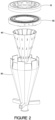
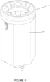
- the cleaning and drying device 10 comprises a housing 20 being a hexagonally shaped tube, a first liner 30 being a dodecagonal shaped funnel within said housing 20, a second liner 40 being a dodecagonal shaped funnel within said first liner 30.
- the housing 20, first liner 30 and second liner 40 have at the top end thereof an annular (ring-shape) cap 50 with an opening for insertion and removal of a spraying unit (not shown) requiring cleaning and subsequent drying.
- the annular (ring shape) cap 50 includes a plurality of air blocks 60 and solvent blocks 70 along the inner diameter thereof.
- the air blocks 60 alternate with the solvent blocks 70, and each are separated from each other by a wall portion of cap 50.
- Each of solvent blocks 70 provide solvent to the cleaning and drying device 10, and in particular, in a direction and flow towards the centre of the opening formed by the annular ring 50 and towards the bottom of the cleaning and drying device 10, in order to direct any unwanted product cleaned from the spraying unit (and used solvent) towards the drain 80 of the first liner 30 (although the drain may be part of the second liner and/or the housing).
- Each of air blocks 60 provides drying air to the cleaning and drying device 10, and in particular, in a direction and flow towards the centre of the opening and towards the bottom of the cleaning and drying device 10 in order to dry the cleaned spraying unit and direct any residual unwanted product cleaned from the spraying unit and/or any residual solvent towards the drain 80 of the first liner 30 (although the drain may be part of the second liner and/or the housing).
- the annular ring/cap 50 in this embodiment, comprises an upper plate 51 and a lower plate 52. Upper plate 51 and lower plate 52 are fastened together with a plurality of plate fasteners, although any fastening method known to a person of ordinary skill may be used. In this instance, the plate fasteners are a series of stainless steel socket cap screws 53 received in cap screw receivers 54.
- Each of cap screw receivers 54 have an upper plate portion and a lower plate portion. Upper plate 51 and lower plate 52, when fastened together, form a series of conduits (channels) running along the inside of cap ring 50.
- Air conduit 55 serves to provide air to each of said air blocks 60.
- Solvent conduit 56 serves to provide solvent to each of said solvent blocks 70.
- Vacuum conduit 57 serves to provide vacuum air to each vacuum air port 58.
- first liner 30 and second liner 40 are cone-like and dodecagonal in shape.
- the cone-like shape denotes the smooth tapering from a top end to a bottom end, with each of the first liner 30 and second liner 40 tapering down towards the drain 80.
- the dodecagonal shape denotes the shape of the walls of each of the first liner 30 and the second liner 40.
- FIG. 3 an exploded view of the cleaning and drying device 10 showing the housing 20 along with the first liner 30 and second liner 40.
- a plurality of base arms 90 located near the drain 80 extend radially outward from the drain 80.
- Each base arm 90 at an end distant the drain 80 further comprises a leg 100 extending normally downward from each base arm 90 and parallel to a central axis of said drain 80.
- Each leg 100 is held securely in place to said respective base arm 90 by a leg pin 110.
- Each end of leg 100 distant the base arm 90 fits into a leg end receiver (not shown) of a base (not shown).
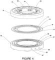
- FIG. 4 , 5A and 5B an exploded view of the annular ring 50 depicting the upper plate 51, lower plate 52, air conduit channel 55 for connecting to air supply port 55', solvent conduit channel 56 for connecting to solvent supply port 56', vacuum conduit channel 57 for connecting to vacuum supply port 57'.
- Each channel 55, 56 and 57 is separated from each other, preferably by a wall, to prevent bleed over and is situated along the length of the annular ring 50.
- a gasket preferably a resilient gasket, preferably a plurality of gaskets, is provided between each channel. The gasket is secured in place when the upper plate 51 is secure to the lower plate 52.
- first ring shaped gasket 11 maintains a seal between air conduit channel 55 and the opening of said device 10; second ring shaped gasket 12, maintains a seal between air conduit channel 55 and solvent conduit channel 56; third ring shaped gasket 13 maintains a seal between solvent conduit channel 56 and vacuum air conduit channel 57; and fourth ring shaped gasket 14 maintains a seal between vacuum air conduit channel 57 and the outside of said device 10.
- first ring shaped gasket 11 maintains a seal between air conduit channel 55 and the opening of said device 10
- second ring shaped gasket 12 maintains a seal between air conduit channel 55 and solvent conduit channel 56
- third ring shaped gasket 13 maintains a seal between solvent conduit channel 56 and vacuum air conduit channel 57
- fourth ring shaped gasket 14 maintains a seal between vacuum air conduit channel 57 and the outside of said device 10.
- the air blocks 60 alternating with the solvent blocks 70.
- FIGS 5A and 5B show the vacuum air supply port 57', drying air supply port 55' and solvent supply port 56', to supply vacuum air, drying air and solvent respectively to the cleaning and drying device 10.
- Vacuum air supply port 57' is in communication with vacuum channel 57 and vacuum outlet ports 58.
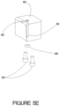
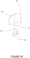
- Drying air supply port 55' is in communication with air conduit channel 55 and air supply aperture 64 and air block nozzle 65 of each air block 60 (see Figures 5E and 5F ).
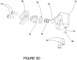
- Solvent supply port 56' is in communication with solvent conduit channel 56 and solvent feed aperture 74 and solvent block nozzle 75 of each solvent block 70 ( Figures 5C and5D).
- Each solvent block receiver 71 and air block receiver 61 being separated by a wall.
- Each solvent block receiver 71 and air block receiver 61 have a solvent feed aperture 220 and air feed aperture 230, respectively, to feed solvent to a solvent block 70 (see Figures 5C and 5D ) and air to an air block 60 (see Figures 5E and 5F ).
- the lower portion of the upper plate 51 depicts a plurality of gasket channels to receive gaskets to keep air and solvent channels separate and avoid bleeding.
- each air block 60 is matingly received and fastened into a complementary air block receiver 61 with an air block fastener.
- the air block fastener is a pair of stainless steel socket cap screws 62 ( Figures 5E-5F ).
- Each solvent block 70 is matingly received and fastened into a complementary solvent block receiver 71 with a solvent block fastener.
- the solvent block fastener is a pair of stainless steel socket cap screws 72 ( Figures 5C-5D ).
- Each air block 60 is separated from each solvent block 70 by a separator wall 140 (although this is optional).
- the air blocks 60 and solvent blocks 70 could also be integral with the annular (ring shape) cap 50, the modularity of the blocks facilitates repair and replacement of each block, if required, without requiring replacement of the entire annular (ring shape) cap 50 and all blocks.
- Figures 5C and 5D depict solvent block 70 comprising a block shape with a solvent block channel 77 running along the inside of the solvent block 70 connecting the solvent feed aperture 74 on the annular ring 50 to the solvent block nozzle 75.
- solvent block nozzle 75 is matingly received into solvent block 70 via a recessed solvent block nozzle-receiving portion 76.
- a check ball 78 Between the solvent block nozzle receiving portion 76 and the solvent block nozzle 75 is a check ball 78 then a spring 79 against said check ball 78.
- the check ball 78 and spring 79 help maintain a seal when solvent flow is not needed.
- the solvent block channel-receiving portion 76 then receives a solvent nozzle seal, in this embodiment a solvent nozzle o-ring 78' to assist in ensuring solvent flow is restricted to the solvent block nozzle 75.
- a retainer plate 79' is provided to retain solvent block nozzle 75, solvent nozzle o-ring 78', spring 79 and solvent check ball 78 in said receiving portion 76.
- the retainer plate 79' is "C" shaped with a centrally located aperture allowing the nozzle 75 to perform as required.
- the retainer plate 79' is held in place with two stainless steel socket cap screws 77'.
- the solvent nozzle 75 has a solvent nozzle stream wall 75' which is angled based on the desired solvent spray pattern for certain applications.
- the angle of the solvent nozzle stream wall 75' may be, but not limited to, 0 to 90 degrees from centre, preferably from 30 to 60 degrees from centre.
- the solvent nozzle is adjustable and may be adjusted within the solvent block 70 to adjust solvent spray pattern as desired.
- volume of solvent may be controlled by orifice size in a flow restrictor which may be mounted proximate or at the solvent supply port 56' at the lower plate 52 of the cap 50.
- solvent supply port 56' may have a predetermined orifice size to control volume of solvent as desired.
- FIGS 5E and 5F depict air block 60 comprises a block shape with an air channel 63 connecting the air supply hole 64 on the annular (ring shape) cap 50 to the air block nozzle 65.
- Air block 60 is secured in place on upper plate 51 via two stainless steel socket cap screws 62.
- Air block nozzle 65 may be adjustable to modify air flow pattern and air flow volume as desired. Although the angle of air block nozzle 65 to air channel 63 is 90 degrees in this depiction, the angle may be adjusted to adjust flow direction and flow pattern as desired. Air nozzle angle may be, but not limited to, from 0 to 90 degrees from centre, preferably from 0 to 15 degrees from centre.
- Each solvent block 70 and air block 60 include a resilient o-ring gasket 66 for a tight seal against the upper plate 51 and minimize bleeding of air or solvent.
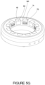
- Figure 5G depicts the annular ring (top cap) 50 when assembled with the alternating air blocks 60 and solvent blocks 70 secured in place.
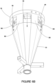
- FIG. 6A depicts the lower plate 52 attached to the second liner 40 via second liner fastener 41.
- second liner fastener 41 In this case two stainless steel cap screws fasten liner 40 to the bottom of the lower plate 52.
- lower plate 52 includes a hexagonal plate 180 on the bottom thereof that serves to engage with lower plate receiver 190 ( Figure 6B ) of the first liner 30.
- Each portion of the hexagonal plate 180 formed by a portion proximate each vertex 181 of the hexagonal plate 180 is received in each lower plate receiver 190.
- Each lower plate receiver 190 is formed by a portion of every other side of the dodecagonal shaped first liner 30. This provides a firm fit of the annular ring 50 with the first liner 30.
- Proximate each vertex of the hexagonal plate 180 is a vacuum air supply aperture to provide air into the housing such that a vacuum is created towards the bottom end of the unit, drawing solvent, air and any product or material cleaned off the cleaning unit.
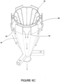
- Figure 6B depicts the first liner 30 fit over the second liner 40 (not seen).
- vacuum air is shown being blown downwards along the outside wall of the first liner at six locations 58 from the lower plate 52 (only three locations visible).
- Figures 6C , 6D and 6E depict the device showing air being directed towards the drain as well as vacuum air blowing downwards along the space formed by the inside wall of the housing and the outside wall of the first liner 30.
- air blown downwards between the first liner and the housing creates a vacuum effect (negative pressure) drawing air down through the second liner and up between the second and first liners.
- Heavy particulates 700 such as paint or the like removed from a spraying unit during the cleaning process and the solvent used in the process rotate and impact the inside wall and vanes of the second liner forming particulates 700.
- the additional corners and vanes in the second liner cause the liquids and VOCs to stop the rotation of the paint (impacting the velocity of paint removed from cap head and air stream) minimizing any VOCs, liquids and paint from moving upwards to the first liner and inside of the housing.
- These particulates 700 will fall to the bottom of the second liner towards the drain or will adhere to the inside of the second liner which may be easily cleaned at a later time.
- Any lighter particulates and vapourized solvent may be drawn upwards between the second and first liners and downwards between the first liner and housing to a scrubber, secondary waste recovery system or equivalent.
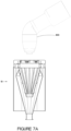
- FIGs 7A-7E there is depicted the cleaning and drying operation of a paint spraying unit 800 requiring cleaning.
- the paint spraying unit 800 is situated proximate the opening of the cleaning and drying device 10.
- the spraying unit 800 begins to be lowered into the opening with the solvent streams 810 and vacuum streams 820 actuated.
- the vacuum streams 820 create a vacuum by directing air downwards thus urging solvent to be directed towards the bottom of the device 10.
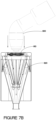
- the spraying unit 800 is partially lowered into the opening of the housing with the solvent spray cleaning the spraying unit and particulates 700 from the spraying unit 800 and solvent being directed downwards towards the drain 80.
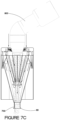
- the solvent streams 810 is closed, the cleaned spraying unit 800 is raised upwards towards the top end and the air streams 830 is actuated to dry the cleaned spraying unit 800 and direct any solvent downwards towards the drain 80.
- the air streams 830 and vacuum streams 820 are closed. The spraying unit is not required to make direct contact with the cleaning and drying device 10.
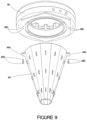
- the second liner 40 with a plurality of elongated vertical vanes 400 connected to the inner wall of the second liner via vertical vane tabs 410 received in vane tab receivers 420 on said second liner (although the vanes may be integral with the second liner).
- removable vertical vanes 400 may be added along the inside wall of the second liner 40 to regulate speed (.e.g., slow down) of the air moving downwards along the inside of the second liner 40.
- the vertical vanes 400 may be from at least one, preferably a plurality, more preferably twelve, depending on the desired air flow control. If there are a plurality of vertical vanes, they are spaced apart from each other to facilitate air flow and speed control. Vertical vane length may vary depending on the desired condition.
- FIG. 9 there is depicted a preferred connection of the second liner 40 to the bottom of the annular cap 50 via second liner screws 430 connecting two second liner tabs 440 extending radially outward from said second liner 40, to second liner screw apertures 450 on the bottom of the annular cap.
- This connection method facilitates removal if necessary as well as provides a secure connection (any suitable connection may be used).
- the first liner 30 is comprised by a number of walls forming a dodecagonal cone.
- each dodecagonal wall 310 comprises a top tab.
- Each dodecagonal wall alternates with a top tab in angle with the adjacent top tab.
- one dodecagonal wall 310 includes a vertically oriented top tab 320.
- the adjacent dodecagonal wall includes an inwardly angled top tab 330.
- every other top tab is vertically oriented to rest against a wall of the hexagonal housing 20, allowing for a point to connect and secure the first liner 30 with the housing 20. This point also serves to secure the annular cap to the housing (see Figures 10 and 11 ).
- the remaining top tabs are inwardly angled towards the centre of the first liner 30 forming a space along the length of the vertex of each wall of said housing 20.
- the remaining top tabs angled inward towards the centre of the first liner 30 also serve to hold the second liner 40 in place by a portion of the outer wall of the second liner 40 resting against the top edge of angled inward top tabs, as well as allow air flow as desired.
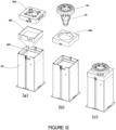
- the existing housing 930 and existing first liner 920 of the unit to be retrofitted will be used.
- an existing cap cleaner top cover 900 and inner liner 910 are removed.
- an existing cap cleaner retrofitted with the assembled cap 50 and second liner 40 allows the existing cap cleaner to have three different streams (solvent, air and vacuum) with the associated benefits described herein.
Landscapes
- Drying Of Solid Materials (AREA)
- Details Or Accessories Of Spraying Plant Or Apparatus (AREA)
Claims (26)
- Vorrichtung zum Reinigen und Trocknen einer Sprüheinheit, wobei die Vorrichtung Folgendes umfasst:ein oberes Ende und ein unteres Ende;wobei das obere und das untere Ende durch ein Gehäuse (20) miteinander verbunden sind;wobei das Gehäuse (20) eine Öffnung in der Nähe des oberen Endes zum Aufnehmen mindestens eines Abschnitts der Sprüheinheit aufweist,eine erste Auskleidung (30) innerhalb des Gehäuses (20),eine zweite Auskleidung (40) innerhalb der ersten Auskleidung (30);wobei die erste Auskleidung (30) in das Gehäuse (20) passt, das einen Raum zwischen einer Außenwand der ersten Auskleidung (30) und einer Innenwand des Gehäuses (20) bildet;ein Großteil der zweiten Auskleidung (40), die in die erste Auskleidung (30) passt, die einen Raum zwischen einer äußeren Wand der zweiten Auskleidung (40) und einer Innenwand der ersten Auskleidung (30) bildet und über einen Großteil der Länge der zweiten Auskleidung (40) verläuft;wobei die Öffnung ferner eine offene ringförmige Kappe (50) in der Nähe des oberen Endes umfasst; wobei die Vorrichtung mindestens einen Vakuumluftzufuhranschluss, mindestens einen Trockenluftzufuhranschluss und mindestens einen Lösungsmittelzufuhranschluss, mindestens einen Vakuumluftzufuhrkanal, der mit der mindestens einem Vakuumluftzufuhranschluss in Verbindung steht, zum Zuführen von Vakuumluft zu mindestens einem Vakuumluftablassanschluss (58) aufweist; mindestens einen Trockenluftzufuhrkanal, der in Verbindung mit dem mindestens einen Trockenluftzufuhranschluss steht, zum Zuführen von Trockenluft zu mindestens einem Trockenluftablassanschluss (65), wobei der mindestens eine Trockenluftablassanschluss in Strömungsrichtung der Trockenluft einstellbar ist; mindestens einen Lösungsmittelzufuhrkanal, der mit dem mindestens einen Lösungsmittelzufuhranschluss in Verbindung steht, zum Zuführen von Lösungsmittel zu mindestens einem Lösungsmittelablassanschluss (75);wobei die mindestens eine Vakuumluftablassöffnung Luft entlang der Außenwand der ersten Auskleidung (30) nach unten strömen lässt, in einer Richtung weg von dem oberen Ende und in Richtung des unteren Endes strömend, wodurch ein Vakuum innerhalb der Vorrichtung erzeugt wird, um Luft durch das obere Ende der Vorrichtung in einer Richtung weg von der Oberseite, nach unten entlang einer Innenwand der zweiten Auskleidung (40) und nach oben zwischen der Außenwand der zweiten Auskleidung (40) und der Innenwand der ersten Auskleidung (30) und nach unten entlang der Außenwand der ersten Auskleidung (30) anzusaugen, um Material und Lösungsmittel in Richtung und aus einem Ablass in der Nähe des unteren Endes anzusaugen;wobei der mindestens eine Trockenluftablassanschluss Luft in der Nähe der Öffnung des Gehäuses (20) bereitstellt, die Luft in einer Richtung zu dem unteren Ende hin strömen lässt; wobei der mindestens eine Lösungsmittelablassanschluss (75) ein Lösungsmittel in der Nähe des oberen Endes der Vorrichtung bereitstellt, die Lösungsmittel in einer Richtung zu dem unteren Ende hin strömen lässt.
- Vorrichtung nach Anspruch 1, ferner umfassend eine Vielzahl von Vakuum luftablassanschlüssen
- Vorrichtung nach Anspruch 1 oder 2, ferner umfassend eine Vielzahl von Trockenluftablassanschlüssen.
- Vorrichtung nach einem der Ansprüche 1-3, ferner umfassend eine Vielzahl von Lösungsmittelablassanschlüssen (75).
- Vorrichtung nach einem der Ansprüche 1-4, wobei der mindestens eine Trockenluftablassanschluss in der Nähe der offenen ringförmigen Kappe (50) ist.
- Vorrichtung nach einem der Ansprüche 1-5, wobei der mindestens eine Lösungsmittelablassanschluss (75) in der Nähe der offenen ringförmigen Kappe (50) ist
- Vorrichtung nach Anspruch 3 und 4, wobei sich jeder der Vielzahl von Trockenluftablassanschlüssen in der Nähe der ringförmigen Kappe (50) mit jedem der Vielzahl von Lösungsmittelablassanschlüssen (75) in der Nähe der offenen ringförmigen Kappe (50) abwechselt.
- Vorrichtung nach einem der Ansprüche 1-7, wobei das Gehäuse (20) eine sechseckige Form aufweist.
- Vorrichtung nach einem der Ansprüche 1-8, wobei die erste Auskleidung (30) eine zwölfeckige konische Form aufweist.
- Vorrichtung nach einem der Ansprüche 1-9, wobei die zweite Auskleidung (40) eine zwölfeckige konische Form aufweist.
- Vorrichtung nach Anspruch 10, wobei die zwölfeckige konische Form der zweiten Auskleidung (40) ferner mindestens eine Schaufel umfasst, die mit der Innenwand der zweiten Auskleidung (40) verbunden ist
- Vorrichtung nach Anspruch 10, wobei die zwölfeckige konische Form der zweiten Auskleidung (40) ferner eine Vielzahl von Schaufeln umfasst, die mit der Innenwand der zweiten Auskleidung (40) verbunden sind.
- Vorrichtung nach Anspruch 11, wobei die mindestens eine Schaufel vertikal entlang der Innenseite der Innenwand der zweiten Auskleidung (40) ausgerichtet ist.
- Vorrichtung nach Anspruch 12, wobei die Vielzahl von Schaufeln vertikal entlang der Innenseite der Innenwand der zweiten Auskleidung (40) ausgerichtet sind
- Vorrichtung nach einem der Ansprüche 1-14, wobei mindestens eine Oberfläche der Vorrichtung glatt ist, um ein Anhaften von unerwünschtem Produkt, Lösungsmittel oder Kombinationen davon an einer Oberfläche der Vorrichtung zu reduzieren.
- Vorrichtung nach einem der Ansprüche 1-14, wobei mindestens eine Oberfläche der Vorrichtung behandelt wird, um ein Anhaften von unerwünschtem Produkt, Lösungsmittel oder Kombinationen davon an einer Oberfläche der Vorrichtung zu reduzieren.
- Vorrichtung nach Anspruch 16, wobei die mindestens eine Oberfläche mit Teflon behandelt ist.
- Vorrichtung nach einem der Ansprüche 1-14, wobei mindestens eine Oberfläche, vorzugsweise eine Vielzahl, der Vorrichtung glatt und behandelt ist, um ein Anhaften von unerwünschtem Produkt, Lösungsmittel oder Kombinationen davon an einer Oberfläche der Vorrichtung zu reduzieren.
- Vorrichtung nach einem der Ansprüche 1-18, wobei die Vorrichtung aus Edelstahl, beschichtetem Stahl, Aluminium und Kombinationen davon ausgewählt ist
- Verfahren zum Reinigen und Trocknen einer Sprüheinheit unter Verwendung einer Vorrichtung nach einem der Ansprüche 1-19, wobei das Verfahren umfasst:i) Einführen einer Sprüheinheit in eine Öffnung der Vorrichtung;ii) Aktivieren einer Vakuumluftquelle und eines Lösungsmittelsprays, während die Sprüheinheit nach unten in die Vorrichtung bewegt wird;iii) Beurteilen der Sauberkeit der Sprüheinheit;iv) Ausschalten des Lösungsmittelsprays;v) Einschalten des Luftsprays; undvi) Bewegen der Sprüheinheit nach oben in die Öffnung.
- Vorrichtung nach Anspruch 1, wobei die offene Kappe (50) eine offene ringförmige Kappe (50) in der Nähe eines Umfangs des oberen Endes ist.
- Vorrichtung nach Anspruch 1, wobei der mindestens eine Trockenluftablassanschluss in Strömungsrichtung der Trockenluft einstellbar ist.
- Vorrichtung nach Anspruch 1, wobei der mindestens eine Lösungsmittelablassanschluss (75) in Strömungsrichtung des Lösungsmittels einstellbar ist.
- Vorrichtung nach Anspruch 4, wobei der mindestens eine Lösungsmittelablassanschluss (75) in dem Volumen des Lösungsmittels einstellbar ist.
- Vorrichtung nach Anspruch 1, wobei der mindestens eine Vakuumluftablassanschluss Luft entlang der Außenwand der zweiten Auskleidung (40) bereitstellt, ermöglicht, dass die Luft, die von dem mindestens einen Vakuumluftablassanschluss bereitgestellt wird, in einer Richtung weg von dem oberen Ende und zu dem unteren Ende strömt, was zu einem Vakuum innerhalb der Vorrichtung führt, um Luft durch das obere Ende der Vorrichtung in einer Richtung weg von der Oberseite entlang der Innenwand der zweiten Auskleidung (40) anzusaugen; ferner saugt sie Luft durch den Raum an, der zwischen der Außenwand der zweiten Auskleidung (40) und der Innenwand der ersten Auskleidung (30) ausgebildet ist, und nach unten durch den Raum, der zwischen der Außenwand der ersten Auskleidung (30) und der Innenwand des Gehäuses (20) ausgebildet ist, hinaus durch das untere Ende der Vorrichtung.
- Reinigungs-, Trocknungs- und Vakuumelement für eine vorhandene Reinigungs- und Trocknungsvorrichtung mit einer Öffnung, einem oberen Ende und einem unteren Ende, wobei das Element Folgendes umfasst:i) eine offene ringförmige Kappe (50);ii) einen konisch geformten Trichter, der an der offenen ringförmigen Kappe (50) angebracht ist; wobei die offene ringförmige Kappe (50) ferner mindestens umfasst: einen Vakuumluftzufuhranschluss, mindestens einen Trockenluftzufuhranschluss und mindestens einen Lösungsmittelzufuhranschluss, mindestens einen Vakuumluftzufuhrkanal, der mit dem mindestens einen Vakuumluftzufuhranschluss in Verbindung steht, zum Zuführen von Vakuumluft zu mindestens einem Vakuumluftablassanschluss (58); mindestens einen Trockenluftzufuhrkanal, der in Verbindung mit dem mindestens einen Trockenluftzufuhranschluss steht, zum Zuführen von Trockenluft zu mindestens einem Trockenluftablassanschluss (65); wobei der mindestens eine Trockenluftablassanschluss (65) in Strömungsrichtung der Trockenluft einstellbar ist; mindestens einen Lösungsmittelzufuhrkanal, der mit dem mindestens einen Lösungsmittelzufuhranschluss in Verbindung steht, zum Zuführen von Lösungsmittel zu mindestens einem Lösungsmittelablassanschluss (75);wobei die mindestens eine Vakuumluftablassöffnung Luft bereitstellt, um Luft in einer Richtung weg von der offenen ringförmigen Kappe (50) und in Richtung des unteren Endes der vorhandenen Reinigungs- und Trocknungsvorrichtung strömen zu lassen, was zu einem Vakuum innerhalb der vorhandenen Reinigungs- und Trocknungsvorrichtung führt, was Luft durch das obere Ende der vorhandenen Reinigungs- und Trocknungsvorrichtung in einer Richtung weg von dem oberen Ende, nach unten entlang einer Innenwand des konisch geformten Trichters ansaugt, wodurch Material und Lösungsmittel in Richtung und aus einem Ablass in der Nähe des unteren Endes der bestehenden Reinigungs- und Trocknungsvorrichtung ansaugt;wobei der mindestens eine Trockenluftablassanschluss Luft in der Nähe der Öffnung der vorhandenen Reinigungs- und Trocknungsvorrichtung bereitstellt, wobei Luft in einer Richtung zu dem unteren Ende der vorhandenen Reinigungs- und Trocknungsvorrichtung strömt;wobei der mindestens eine Lösungsmittelablassanschluss (75) ein Lösungsmittel in der Nähe des oberen Endes der vorhandenen Reinigungs- und Trocknungsvorrichtung bereitstellt, wobei Lösungsmittel in einer Richtung zu dem unteren Ende strömt, wobei das obere Ende und das untere Ende durch ein Gehäuse (20) miteinander verbunden sind;wobei der konisch geformte Trichter eine erste Auskleidung (30) aus einem zwölfseitig geformten Trichter und einer zweiten Auskleidung (40) aus einem zwölfseitig geformten Trichter umfasst;wobei die zweite Auskleidung (40) ferner eine Vielzahl von beabstandeten länglichen vertikalen Schaufeln (400) umfasst; wobei ein Großteil der zweiten Auskleidung (40), die in die erste Auskleidung (30) passt, einen Raum zwischen einer Außenwand der zweiten Auskleidung (40) und einer Innenwand der ersten Auskleidung (30) bildet und über einen Großteil der Länge der zweiten Auskleidung (40) verläuft.
Applications Claiming Priority (1)
| Application Number | Priority Date | Filing Date | Title |
|---|---|---|---|
| PCT/CA2016/051455 WO2018102907A1 (en) | 2016-12-09 | 2016-12-09 | Device for cleaning and drying a spraying unit |
Publications (3)
| Publication Number | Publication Date |
|---|---|
| EP3551346A1 EP3551346A1 (de) | 2019-10-16 |
| EP3551346A4 EP3551346A4 (de) | 2020-08-05 |
| EP3551346B1 true EP3551346B1 (de) | 2023-07-12 |
Family
ID=62490593
Family Applications (1)
| Application Number | Title | Priority Date | Filing Date |
|---|---|---|---|
| EP16923141.2A Active EP3551346B1 (de) | 2016-12-09 | 2016-12-09 | Vorrichtung zum reinigen und trocknen einer sprüheinheit |
Country Status (6)
| Country | Link |
|---|---|
| US (1) | US11253884B2 (de) |
| EP (1) | EP3551346B1 (de) |
| JP (1) | JP6913403B2 (de) |
| CN (1) | CN110072634B (de) |
| CA (1) | CA3045047C (de) |
| WO (1) | WO2018102907A1 (de) |
Families Citing this family (8)
| Publication number | Priority date | Publication date | Assignee | Title |
|---|---|---|---|---|
| CN110035835B (zh) | 2016-11-17 | 2021-11-09 | 菲力普·杰赛普 | 用于对油漆涂装器进行低压非接触清洗的装置 |
| KR102532733B1 (ko) * | 2018-02-14 | 2023-05-16 | 삼성디스플레이 주식회사 | 분진 제거 장치 및 이를 포함하는 레이저 커팅 장치 |
| CN110586395B (zh) * | 2019-09-12 | 2020-12-25 | 四川富生电器有限责任公司 | 一种防粘附的电机嵌线润滑油喷头结构 |
| TWI715369B (zh) * | 2019-12-24 | 2021-01-01 | 萬潤科技股份有限公司 | 吸液組件、液材承接方法及裝置 |
| CN112547393B (zh) * | 2020-11-30 | 2022-03-11 | 浙江瑞丰五福气动工具有限公司 | 气动喷枪喷漆工作台 |
| WO2023187940A1 (ja) * | 2022-03-28 | 2023-10-05 | トリニティ工業株式会社 | 塗装機洗浄用ホッパー |
| CN115502011B (zh) * | 2022-10-18 | 2023-07-21 | 东莞鹏龙光电有限公司 | 一种用于生产显示模组的智能生产设备 |
| CN117797962B (zh) * | 2024-02-29 | 2024-05-31 | 江苏南极机械有限责任公司 | 一种船舶压载水舱免涂装防腐喷头 |
Family Cites Families (13)
| Publication number | Priority date | Publication date | Assignee | Title |
|---|---|---|---|---|
| SE447799B (sv) * | 1986-01-20 | 1986-12-15 | Stern Leif Einar | Anordning for att hos sprutpistoler rengora fergdistributionskanaler |
| US5174317A (en) * | 1986-09-05 | 1992-12-29 | Herkules Equipment Corporation | Spray gun and associate parts washer and recycler |
| DE3808801A1 (de) * | 1988-03-16 | 1989-10-05 | Behr Industrieanlagen | Verfahren und vorrichtung zum reinigen einer spruehvorrichtung |
| US4934393A (en) | 1988-06-30 | 1990-06-19 | John S. Lighthall | Spray gun cleaning apparatus |
| US5693150A (en) * | 1996-05-03 | 1997-12-02 | Aeg Automation Systems Corporation | Automatic paint gun cleaner |
| CN2538433Y (zh) | 2002-02-21 | 2003-03-05 | 洽昌工业股份有限公司 | 喷漆枪的自动清洗装置 |
| DE10394135B4 (de) * | 2003-02-21 | 2012-07-05 | Philip Jessup | Kontaktfreie Sprühgerät-Reinigungsvorrichtung |
| US7597767B1 (en) * | 2005-03-31 | 2009-10-06 | Honda Motor Co., Ltd. | Paint gun cleaning apparatus |
| CN101537400B (zh) * | 2008-03-18 | 2013-11-06 | 菲利普·约瑟夫 | 喷漆设备清洁装置 |
| US9221068B2 (en) * | 2013-10-09 | 2015-12-29 | Philip Jessup | Apparatus for non-contact cleaning a paint spray tip |
| CN105127037A (zh) * | 2015-07-17 | 2015-12-09 | 深圳市泰达机器人有限公司 | 一种喷具全自动清洗装置 |
| CN110035835B (zh) * | 2016-11-17 | 2021-11-09 | 菲力普·杰赛普 | 用于对油漆涂装器进行低压非接触清洗的装置 |
| JP6492225B2 (ja) * | 2016-11-22 | 2019-03-27 | クリスタル キャップ クリーナーズ インコーポレーテッドCrystal Cap Cleaners Inc. | 改良型スプレーガン洗浄装置 |
-
2016
- 2016-12-09 CN CN201680091436.3A patent/CN110072634B/zh active Active
- 2016-12-09 EP EP16923141.2A patent/EP3551346B1/de active Active
- 2016-12-09 CA CA3045047A patent/CA3045047C/en active Active
- 2016-12-09 US US16/466,189 patent/US11253884B2/en active Active
- 2016-12-09 JP JP2019530653A patent/JP6913403B2/ja active Active
- 2016-12-09 WO PCT/CA2016/051455 patent/WO2018102907A1/en not_active Ceased
Also Published As
| Publication number | Publication date |
|---|---|
| US11253884B2 (en) | 2022-02-22 |
| EP3551346A4 (de) | 2020-08-05 |
| JP6913403B2 (ja) | 2021-08-04 |
| CN110072634B (zh) | 2022-02-22 |
| CA3045047A1 (en) | 2018-06-14 |
| CA3045047C (en) | 2023-08-29 |
| WO2018102907A1 (en) | 2018-06-14 |
| EP3551346A1 (de) | 2019-10-16 |
| JP2020503168A (ja) | 2020-01-30 |
| CN110072634A (zh) | 2019-07-30 |
| US20200147633A1 (en) | 2020-05-14 |
Similar Documents
| Publication | Publication Date | Title |
|---|---|---|
| EP3551346B1 (de) | Vorrichtung zum reinigen und trocknen einer sprüheinheit | |
| CN108323161B (zh) | 用于清洁喷枪的改进装置 | |
| CN103464328B (zh) | 漆雾分离装置 | |
| JP5721084B2 (ja) | マイクロエレクトロニクス用の加工物を処理するための装置 | |
| CN100372615C (zh) | 喷射系统及该系统中的喷射装置的制造方法 | |
| US9441831B2 (en) | Laminar water fountain | |
| CN106457275A (zh) | 清洁装置及相关联的操作方法 | |
| CN108136428A (zh) | 用于针头喷嘴的清洁站 | |
| KR102094162B1 (ko) | 석면 분진 제거용 분무장치 | |
| CN112044652A (zh) | 一种喷涂雾化器清洗专用装置 | |
| US7954446B2 (en) | Hopper for cleaning coating machine | |
| CN208627642U (zh) | 用于露天建筑场地的除尘喷头 | |
| RU2727626C1 (ru) | Лакировально-окрасочная установка, способ лакокрасочной обработки детали и фильтрующий элемент для них | |
| KR101784210B1 (ko) | 응축수 원심분리기능을 구비한 에어분배기 | |
| WO2019132661A1 (en) | Washing device for washing objects, and sprayer, conversion kit and method therefor | |
| US11286654B2 (en) | Waste disposer with embedded sprinkler assembly | |
| US7597767B1 (en) | Paint gun cleaning apparatus | |
| KR102814457B1 (ko) | 피스톨레 공간 제공 박스 | |
| SE506851C2 (sv) | Munstycke för invändig rengöring och/eller målning av rörledningar | |
| CN204564410U (zh) | 一种具转向吸排及高压吹气的喷头构造 | |
| EP1800761B1 (de) | Vorrichtung zum Atomisieren und Versprühen einer Solemischung | |
| US20190243129A1 (en) | Sight glass cover with integrated cleaning device | |
| SG10201802425VA (en) | Self-cleaning discard cyclone separator system | |
| NZ781101A (en) | Apparatus and method for spray drying | |
| NZ781101B2 (en) | Apparatus and method for spray drying |
Legal Events
| Date | Code | Title | Description |
|---|---|---|---|
| STAA | Information on the status of an ep patent application or granted ep patent |
Free format text: STATUS: THE INTERNATIONAL PUBLICATION HAS BEEN MADE |
|
| PUAI | Public reference made under article 153(3) epc to a published international application that has entered the european phase |
Free format text: ORIGINAL CODE: 0009012 |
|
| STAA | Information on the status of an ep patent application or granted ep patent |
Free format text: STATUS: REQUEST FOR EXAMINATION WAS MADE |
|
| 17P | Request for examination filed |
Effective date: 20190529 |
|
| AK | Designated contracting states |
Kind code of ref document: A1 Designated state(s): AL AT BE BG CH CY CZ DE DK EE ES FI FR GB GR HR HU IE IS IT LI LT LU LV MC MK MT NL NO PL PT RO RS SE SI SK SM TR |
|
| AX | Request for extension of the european patent |
Extension state: BA ME |
|
| DAV | Request for validation of the european patent (deleted) | ||
| DAX | Request for extension of the european patent (deleted) | ||
| A4 | Supplementary search report drawn up and despatched |
Effective date: 20200702 |
|
| RIC1 | Information provided on ipc code assigned before grant |
Ipc: B05B 15/50 20180101AFI20200626BHEP Ipc: B05B 14/49 20180101ALI20200626BHEP Ipc: B05B 15/555 20180101ALI20200626BHEP Ipc: B08B 15/02 20060101ALI20200626BHEP |
|
| STAA | Information on the status of an ep patent application or granted ep patent |
Free format text: STATUS: EXAMINATION IS IN PROGRESS |
|
| 17Q | First examination report despatched |
Effective date: 20220803 |
|
| GRAP | Despatch of communication of intention to grant a patent |
Free format text: ORIGINAL CODE: EPIDOSNIGR1 |
|
| STAA | Information on the status of an ep patent application or granted ep patent |
Free format text: STATUS: GRANT OF PATENT IS INTENDED |
|
| INTG | Intention to grant announced |
Effective date: 20230214 |
|
| RIN1 | Information on inventor provided before grant (corrected) |
Inventor name: DOYLE, JAMES LAURENCE |
|
| GRAS | Grant fee paid |
Free format text: ORIGINAL CODE: EPIDOSNIGR3 |
|
| GRAA | (expected) grant |
Free format text: ORIGINAL CODE: 0009210 |
|
| STAA | Information on the status of an ep patent application or granted ep patent |
Free format text: STATUS: THE PATENT HAS BEEN GRANTED |
|
| AK | Designated contracting states |
Kind code of ref document: B1 Designated state(s): AL AT BE BG CH CY CZ DE DK EE ES FI FR GB GR HR HU IE IS IT LI LT LU LV MC MK MT NL NO PL PT RO RS SE SI SK SM TR |
|
| REG | Reference to a national code |
Ref country code: CH Ref legal event code: EP |
|
| REG | Reference to a national code |
Ref country code: DE Ref legal event code: R096 Ref document number: 602016081083 Country of ref document: DE |
|
| REG | Reference to a national code |
Ref country code: IE Ref legal event code: FG4D |
|
| REG | Reference to a national code |
Ref country code: LT Ref legal event code: MG9D |
|
| P01 | Opt-out of the competence of the unified patent court (upc) registered |
Effective date: 20231005 |
|
| REG | Reference to a national code |
Ref country code: NL Ref legal event code: MP Effective date: 20230712 |
|
| REG | Reference to a national code |
Ref country code: AT Ref legal event code: MK05 Ref document number: 1586545 Country of ref document: AT Kind code of ref document: T Effective date: 20230712 |
|
| PG25 | Lapsed in a contracting state [announced via postgrant information from national office to epo] |
Ref country code: NL Free format text: LAPSE BECAUSE OF FAILURE TO SUBMIT A TRANSLATION OF THE DESCRIPTION OR TO PAY THE FEE WITHIN THE PRESCRIBED TIME-LIMIT Effective date: 20230712 |
|
| PG25 | Lapsed in a contracting state [announced via postgrant information from national office to epo] |
Ref country code: GR Free format text: LAPSE BECAUSE OF FAILURE TO SUBMIT A TRANSLATION OF THE DESCRIPTION OR TO PAY THE FEE WITHIN THE PRESCRIBED TIME-LIMIT Effective date: 20231013 |
|
| PG25 | Lapsed in a contracting state [announced via postgrant information from national office to epo] |
Ref country code: ES Free format text: LAPSE BECAUSE OF FAILURE TO SUBMIT A TRANSLATION OF THE DESCRIPTION OR TO PAY THE FEE WITHIN THE PRESCRIBED TIME-LIMIT Effective date: 20230712 |
|
| PG25 | Lapsed in a contracting state [announced via postgrant information from national office to epo] |
Ref country code: IS Free format text: LAPSE BECAUSE OF FAILURE TO SUBMIT A TRANSLATION OF THE DESCRIPTION OR TO PAY THE FEE WITHIN THE PRESCRIBED TIME-LIMIT Effective date: 20231112 |
|
| PG25 | Lapsed in a contracting state [announced via postgrant information from national office to epo] |
Ref country code: SE Free format text: LAPSE BECAUSE OF FAILURE TO SUBMIT A TRANSLATION OF THE DESCRIPTION OR TO PAY THE FEE WITHIN THE PRESCRIBED TIME-LIMIT Effective date: 20230712 Ref country code: RS Free format text: LAPSE BECAUSE OF FAILURE TO SUBMIT A TRANSLATION OF THE DESCRIPTION OR TO PAY THE FEE WITHIN THE PRESCRIBED TIME-LIMIT Effective date: 20230712 Ref country code: PT Free format text: LAPSE BECAUSE OF FAILURE TO SUBMIT A TRANSLATION OF THE DESCRIPTION OR TO PAY THE FEE WITHIN THE PRESCRIBED TIME-LIMIT Effective date: 20231113 Ref country code: NO Free format text: LAPSE BECAUSE OF FAILURE TO SUBMIT A TRANSLATION OF THE DESCRIPTION OR TO PAY THE FEE WITHIN THE PRESCRIBED TIME-LIMIT Effective date: 20231012 Ref country code: LV Free format text: LAPSE BECAUSE OF FAILURE TO SUBMIT A TRANSLATION OF THE DESCRIPTION OR TO PAY THE FEE WITHIN THE PRESCRIBED TIME-LIMIT Effective date: 20230712 Ref country code: LT Free format text: LAPSE BECAUSE OF FAILURE TO SUBMIT A TRANSLATION OF THE DESCRIPTION OR TO PAY THE FEE WITHIN THE PRESCRIBED TIME-LIMIT Effective date: 20230712 Ref country code: IS Free format text: LAPSE BECAUSE OF FAILURE TO SUBMIT A TRANSLATION OF THE DESCRIPTION OR TO PAY THE FEE WITHIN THE PRESCRIBED TIME-LIMIT Effective date: 20231112 Ref country code: HR Free format text: LAPSE BECAUSE OF FAILURE TO SUBMIT A TRANSLATION OF THE DESCRIPTION OR TO PAY THE FEE WITHIN THE PRESCRIBED TIME-LIMIT Effective date: 20230712 Ref country code: GR Free format text: LAPSE BECAUSE OF FAILURE TO SUBMIT A TRANSLATION OF THE DESCRIPTION OR TO PAY THE FEE WITHIN THE PRESCRIBED TIME-LIMIT Effective date: 20231013 Ref country code: FI Free format text: LAPSE BECAUSE OF FAILURE TO SUBMIT A TRANSLATION OF THE DESCRIPTION OR TO PAY THE FEE WITHIN THE PRESCRIBED TIME-LIMIT Effective date: 20230712 Ref country code: ES Free format text: LAPSE BECAUSE OF FAILURE TO SUBMIT A TRANSLATION OF THE DESCRIPTION OR TO PAY THE FEE WITHIN THE PRESCRIBED TIME-LIMIT Effective date: 20230712 Ref country code: AT Free format text: LAPSE BECAUSE OF FAILURE TO SUBMIT A TRANSLATION OF THE DESCRIPTION OR TO PAY THE FEE WITHIN THE PRESCRIBED TIME-LIMIT Effective date: 20230712 |
|
| PG25 | Lapsed in a contracting state [announced via postgrant information from national office to epo] |
Ref country code: PL Free format text: LAPSE BECAUSE OF FAILURE TO SUBMIT A TRANSLATION OF THE DESCRIPTION OR TO PAY THE FEE WITHIN THE PRESCRIBED TIME-LIMIT Effective date: 20230712 |
|
| REG | Reference to a national code |
Ref country code: DE Ref legal event code: R097 Ref document number: 602016081083 Country of ref document: DE |
|
| PG25 | Lapsed in a contracting state [announced via postgrant information from national office to epo] |
Ref country code: SM Free format text: LAPSE BECAUSE OF FAILURE TO SUBMIT A TRANSLATION OF THE DESCRIPTION OR TO PAY THE FEE WITHIN THE PRESCRIBED TIME-LIMIT Effective date: 20230712 Ref country code: RO Free format text: LAPSE BECAUSE OF FAILURE TO SUBMIT A TRANSLATION OF THE DESCRIPTION OR TO PAY THE FEE WITHIN THE PRESCRIBED TIME-LIMIT Effective date: 20230712 Ref country code: EE Free format text: LAPSE BECAUSE OF FAILURE TO SUBMIT A TRANSLATION OF THE DESCRIPTION OR TO PAY THE FEE WITHIN THE PRESCRIBED TIME-LIMIT Effective date: 20230712 Ref country code: DK Free format text: LAPSE BECAUSE OF FAILURE TO SUBMIT A TRANSLATION OF THE DESCRIPTION OR TO PAY THE FEE WITHIN THE PRESCRIBED TIME-LIMIT Effective date: 20230712 Ref country code: CZ Free format text: LAPSE BECAUSE OF FAILURE TO SUBMIT A TRANSLATION OF THE DESCRIPTION OR TO PAY THE FEE WITHIN THE PRESCRIBED TIME-LIMIT Effective date: 20230712 Ref country code: SK Free format text: LAPSE BECAUSE OF FAILURE TO SUBMIT A TRANSLATION OF THE DESCRIPTION OR TO PAY THE FEE WITHIN THE PRESCRIBED TIME-LIMIT Effective date: 20230712 |
|
| PLBE | No opposition filed within time limit |
Free format text: ORIGINAL CODE: 0009261 |
|
| STAA | Information on the status of an ep patent application or granted ep patent |
Free format text: STATUS: NO OPPOSITION FILED WITHIN TIME LIMIT |
|
| PG25 | Lapsed in a contracting state [announced via postgrant information from national office to epo] |
Ref country code: IT Free format text: LAPSE BECAUSE OF FAILURE TO SUBMIT A TRANSLATION OF THE DESCRIPTION OR TO PAY THE FEE WITHIN THE PRESCRIBED TIME-LIMIT Effective date: 20230712 |
|
| 26N | No opposition filed |
Effective date: 20240415 |
|
| PG25 | Lapsed in a contracting state [announced via postgrant information from national office to epo] |
Ref country code: SI Free format text: LAPSE BECAUSE OF FAILURE TO SUBMIT A TRANSLATION OF THE DESCRIPTION OR TO PAY THE FEE WITHIN THE PRESCRIBED TIME-LIMIT Effective date: 20230712 |
|
| REG | Reference to a national code |
Ref country code: CH Ref legal event code: PL |
|
| PG25 | Lapsed in a contracting state [announced via postgrant information from national office to epo] |
Ref country code: LU Free format text: LAPSE BECAUSE OF NON-PAYMENT OF DUE FEES Effective date: 20231209 |
|
| PG25 | Lapsed in a contracting state [announced via postgrant information from national office to epo] |
Ref country code: MC Free format text: LAPSE BECAUSE OF FAILURE TO SUBMIT A TRANSLATION OF THE DESCRIPTION OR TO PAY THE FEE WITHIN THE PRESCRIBED TIME-LIMIT Effective date: 20230712 |
|
| REG | Reference to a national code |
Ref country code: BE Ref legal event code: MM Effective date: 20231231 |
|
| PG25 | Lapsed in a contracting state [announced via postgrant information from national office to epo] |
Ref country code: MC Free format text: LAPSE BECAUSE OF FAILURE TO SUBMIT A TRANSLATION OF THE DESCRIPTION OR TO PAY THE FEE WITHIN THE PRESCRIBED TIME-LIMIT Effective date: 20230712 Ref country code: LU Free format text: LAPSE BECAUSE OF NON-PAYMENT OF DUE FEES Effective date: 20231209 |
|
| REG | Reference to a national code |
Ref country code: IE Ref legal event code: MM4A |
|
| PG25 | Lapsed in a contracting state [announced via postgrant information from national office to epo] |
Ref country code: IE Free format text: LAPSE BECAUSE OF NON-PAYMENT OF DUE FEES Effective date: 20231209 |
|
| PG25 | Lapsed in a contracting state [announced via postgrant information from national office to epo] |
Ref country code: BE Free format text: LAPSE BECAUSE OF NON-PAYMENT OF DUE FEES Effective date: 20231231 |
|
| PG25 | Lapsed in a contracting state [announced via postgrant information from national office to epo] |
Ref country code: CH Free format text: LAPSE BECAUSE OF NON-PAYMENT OF DUE FEES Effective date: 20231231 |
|
| PG25 | Lapsed in a contracting state [announced via postgrant information from national office to epo] |
Ref country code: IE Free format text: LAPSE BECAUSE OF NON-PAYMENT OF DUE FEES Effective date: 20231209 Ref country code: CH Free format text: LAPSE BECAUSE OF NON-PAYMENT OF DUE FEES Effective date: 20231231 Ref country code: BE Free format text: LAPSE BECAUSE OF NON-PAYMENT OF DUE FEES Effective date: 20231231 |
|
| PG25 | Lapsed in a contracting state [announced via postgrant information from national office to epo] |
Ref country code: BG Free format text: LAPSE BECAUSE OF FAILURE TO SUBMIT A TRANSLATION OF THE DESCRIPTION OR TO PAY THE FEE WITHIN THE PRESCRIBED TIME-LIMIT Effective date: 20230712 |
|
| PG25 | Lapsed in a contracting state [announced via postgrant information from national office to epo] |
Ref country code: BG Free format text: LAPSE BECAUSE OF FAILURE TO SUBMIT A TRANSLATION OF THE DESCRIPTION OR TO PAY THE FEE WITHIN THE PRESCRIBED TIME-LIMIT Effective date: 20230712 |
|
| PG25 | Lapsed in a contracting state [announced via postgrant information from national office to epo] |
Ref country code: CY Free format text: LAPSE BECAUSE OF FAILURE TO SUBMIT A TRANSLATION OF THE DESCRIPTION OR TO PAY THE FEE WITHIN THE PRESCRIBED TIME-LIMIT; INVALID AB INITIO Effective date: 20161209 |
|
| PG25 | Lapsed in a contracting state [announced via postgrant information from national office to epo] |
Ref country code: HU Free format text: LAPSE BECAUSE OF FAILURE TO SUBMIT A TRANSLATION OF THE DESCRIPTION OR TO PAY THE FEE WITHIN THE PRESCRIBED TIME-LIMIT; INVALID AB INITIO Effective date: 20161209 |
|
| PG25 | Lapsed in a contracting state [announced via postgrant information from national office to epo] |
Ref country code: TR Free format text: LAPSE BECAUSE OF FAILURE TO SUBMIT A TRANSLATION OF THE DESCRIPTION OR TO PAY THE FEE WITHIN THE PRESCRIBED TIME-LIMIT Effective date: 20230712 |
|
| PGFP | Annual fee paid to national office [announced via postgrant information from national office to epo] |
Ref country code: DE Payment date: 20251119 Year of fee payment: 10 |
|
| PGFP | Annual fee paid to national office [announced via postgrant information from national office to epo] |
Ref country code: GB Payment date: 20251021 Year of fee payment: 10 |
|
| PGFP | Annual fee paid to national office [announced via postgrant information from national office to epo] |
Ref country code: FR Payment date: 20251119 Year of fee payment: 10 |