EP3551346B1 - Device for cleaning and drying a spraying unit - Google Patents
Device for cleaning and drying a spraying unit Download PDFInfo
- Publication number
- EP3551346B1 EP3551346B1 EP16923141.2A EP16923141A EP3551346B1 EP 3551346 B1 EP3551346 B1 EP 3551346B1 EP 16923141 A EP16923141 A EP 16923141A EP 3551346 B1 EP3551346 B1 EP 3551346B1
- Authority
- EP
- European Patent Office
- Prior art keywords
- liner
- solvent
- air
- drying
- port
- Prior art date
- Legal status (The legal status is an assumption and is not a legal conclusion. Google has not performed a legal analysis and makes no representation as to the accuracy of the status listed.)
- Active
Links
- 238000001035 drying Methods 0.000 title claims description 69
- 238000004140 cleaning Methods 0.000 title claims description 62
- 238000005507 spraying Methods 0.000 title claims description 34
- 239000002904 solvent Substances 0.000 claims description 130
- 239000007921 spray Substances 0.000 claims description 10
- 238000004891 communication Methods 0.000 claims description 9
- 229910001220 stainless steel Inorganic materials 0.000 claims description 8
- 239000010935 stainless steel Substances 0.000 claims description 8
- 239000000463 material Substances 0.000 claims description 7
- 238000000034 method Methods 0.000 claims description 6
- 229910000831 Steel Inorganic materials 0.000 claims description 2
- 239000004809 Teflon Substances 0.000 claims description 2
- 229910052782 aluminium Inorganic materials 0.000 claims description 2
- XAGFODPZIPBFFR-UHFFFAOYSA-N aluminium Chemical compound [Al] XAGFODPZIPBFFR-UHFFFAOYSA-N 0.000 claims description 2
- 239000010959 steel Substances 0.000 claims description 2
- 229920006362 Teflon® Polymers 0.000 claims 1
- 230000003213 activating effect Effects 0.000 claims 1
- 230000003749 cleanliness Effects 0.000 claims 1
- 239000003973 paint Substances 0.000 description 8
- 239000012855 volatile organic compound Substances 0.000 description 5
- 239000007788 liquid Substances 0.000 description 4
- 230000000740 bleeding effect Effects 0.000 description 2
- 230000000295 complement effect Effects 0.000 description 2
- 238000011084 recovery Methods 0.000 description 2
- 238000007664 blowing Methods 0.000 description 1
- 238000010276 construction Methods 0.000 description 1
- 238000010981 drying operation Methods 0.000 description 1
- 230000000694 effects Effects 0.000 description 1
- 230000003116 impacting effect Effects 0.000 description 1
- 238000003780 insertion Methods 0.000 description 1
- 230000037431 insertion Effects 0.000 description 1
- 238000012423 maintenance Methods 0.000 description 1
- 239000013557 residual solvent Substances 0.000 description 1
- 230000000284 resting effect Effects 0.000 description 1
- 238000009420 retrofitting Methods 0.000 description 1
- 239000002699 waste material Substances 0.000 description 1
- XLYOFNOQVPJJNP-UHFFFAOYSA-N water Substances O XLYOFNOQVPJJNP-UHFFFAOYSA-N 0.000 description 1
Images


Classifications
-
- B—PERFORMING OPERATIONS; TRANSPORTING
- B05—SPRAYING OR ATOMISING IN GENERAL; APPLYING FLUENT MATERIALS TO SURFACES, IN GENERAL
- B05B—SPRAYING APPARATUS; ATOMISING APPARATUS; NOZZLES
- B05B15/00—Details of spraying plant or spraying apparatus not otherwise provided for; Accessories
- B05B15/50—Arrangements for cleaning; Arrangements for preventing deposits, drying-out or blockage; Arrangements for detecting improper discharge caused by the presence of foreign matter
- B05B15/55—Arrangements for cleaning; Arrangements for preventing deposits, drying-out or blockage; Arrangements for detecting improper discharge caused by the presence of foreign matter using cleaning fluids
- B05B15/555—Arrangements for cleaning; Arrangements for preventing deposits, drying-out or blockage; Arrangements for detecting improper discharge caused by the presence of foreign matter using cleaning fluids discharged by cleaning nozzles
-
- B—PERFORMING OPERATIONS; TRANSPORTING
- B05—SPRAYING OR ATOMISING IN GENERAL; APPLYING FLUENT MATERIALS TO SURFACES, IN GENERAL
- B05B—SPRAYING APPARATUS; ATOMISING APPARATUS; NOZZLES
- B05B14/00—Arrangements for collecting, re-using or eliminating excess spraying material
- B05B14/40—Arrangements for collecting, re-using or eliminating excess spraying material for use in spray booths
- B05B14/49—Arrangements for collecting, re-using or eliminating excess spraying material for use in spray booths specially adapted for solvents
-
- B—PERFORMING OPERATIONS; TRANSPORTING
- B05—SPRAYING OR ATOMISING IN GENERAL; APPLYING FLUENT MATERIALS TO SURFACES, IN GENERAL
- B05B—SPRAYING APPARATUS; ATOMISING APPARATUS; NOZZLES
- B05B15/00—Details of spraying plant or spraying apparatus not otherwise provided for; Accessories
- B05B15/50—Arrangements for cleaning; Arrangements for preventing deposits, drying-out or blockage; Arrangements for detecting improper discharge caused by the presence of foreign matter
- B05B15/55—Arrangements for cleaning; Arrangements for preventing deposits, drying-out or blockage; Arrangements for detecting improper discharge caused by the presence of foreign matter using cleaning fluids
-
- B—PERFORMING OPERATIONS; TRANSPORTING
- B08—CLEANING
- B08B—CLEANING IN GENERAL; PREVENTION OF FOULING IN GENERAL
- B08B3/00—Cleaning by methods involving the use or presence of liquid or steam
- B08B3/02—Cleaning by the force of jets or sprays
-
- B—PERFORMING OPERATIONS; TRANSPORTING
- B05—SPRAYING OR ATOMISING IN GENERAL; APPLYING FLUENT MATERIALS TO SURFACES, IN GENERAL
- B05B—SPRAYING APPARATUS; ATOMISING APPARATUS; NOZZLES
- B05B13/00—Machines or plants for applying liquids or other fluent materials to surfaces of objects or other work by spraying, not covered by groups B05B1/00 - B05B11/00
- B05B13/02—Means for supporting work; Arrangement or mounting of spray heads; Adaptation or arrangement of means for feeding work
- B05B13/04—Means for supporting work; Arrangement or mounting of spray heads; Adaptation or arrangement of means for feeding work the spray heads being moved during spraying operation
- B05B13/0405—Means for supporting work; Arrangement or mounting of spray heads; Adaptation or arrangement of means for feeding work the spray heads being moved during spraying operation with reciprocating or oscillating spray heads
-
- B—PERFORMING OPERATIONS; TRANSPORTING
- B08—CLEANING
- B08B—CLEANING IN GENERAL; PREVENTION OF FOULING IN GENERAL
- B08B15/00—Preventing escape of dirt or fumes from the area where they are produced; Collecting or removing dirt or fumes from that area
- B08B15/02—Preventing escape of dirt or fumes from the area where they are produced; Collecting or removing dirt or fumes from that area using chambers or hoods covering the area
- B08B15/026—Boxes for removal of dirt, e.g. for cleaning brakes, glove- boxes
-
- B—PERFORMING OPERATIONS; TRANSPORTING
- B08—CLEANING
- B08B—CLEANING IN GENERAL; PREVENTION OF FOULING IN GENERAL
- B08B2203/00—Details of cleaning machines or methods involving the use or presence of liquid or steam
- B08B2203/02—Details of machines or methods for cleaning by the force of jets or sprays
- B08B2203/0229—Suction chambers for aspirating the sprayed liquid
Definitions
- This disclosure relates to a device for cleaning and drying a spraying unit, in particular, for cleaning a paint-spraying unit.
- a component of the cleaning and drying device may also be retrofitted into existing cleaning and drying devices.
- Typical cleaning devices for cleaning a spraying unit include a single solvent stream and a single air stream.
- the solvent stream is used to remove unwanted material from the spraying unit and the air is used to assist in further removal of unwanted material and dry the cleaned spraying unit.
- the exhaust from the cleaning devices comprise significant liquids and volatile organic compounds ("VOCs").
- Some cleaning devices do not effectively clean and dry the spraying unit with water borne products on the spraying unit.
- Some cleaning devices experience residue caking on the inner walls thereof and retaining of dirt resulting in inefficiency of the cleaning devices as well as increased down time for maintenance and cleaning of the devices. In some instances, attempts to clean the cleaning devices of caked on residue and dirt further blocks the solvent recovery system of the cleaning devices.
- Existing/Currently available cleaning devices have stationary air outlets.
- a cleaning and drying device that reduces residue caking.
- a cleaning and drying device that includes directional and/or adjustable air outlets or air outlets that may accommodate varying air directions and/or flow pattern.
- a cleaning and drying device that includes directional and/or adjustable solvent outlets or solvent outlets that may accommodate varying solvent directions and/or flow pattern.
- a cleaning and drying device that reduces the potential of unwanted material to adhere to the outside surfaces as well as the exhaust passage and further areas that are inaccessible to cleaning a surface of a cleaning and drying device.
- a cleaning and drying device which reduces liquids and VOCs from the exhaust thereof.
- a component of a cleaning and drying device that may be retrofitted into existing cleaning/drying devices.
- Document CN101537400 discloses a device for drying a spray gun used in an automatic manufactory.
- the device is an effective two-stage solvent reclaiming system to lower cost in aspects of operation and environment.
- the device comprises a main body for accommodating a solvent spray head which is used for cleaning and inserted into the main body through non-contact seal, and an air spray head for cleaning an article once the article is cleaned.
- a low pressure area is generated in the main body by downwards guiding the air spray head so as to keep the air carried with a solvent in the main body.
- the air carried with the solvent is guided to a solvent separator positioned under the main body to reclaim the solvent.
- a device for cleaning and drying a spraying unit preferably a paint-spraying unit, more preferably a paint outlet of a paint spraying unit, according to claim 1.
- said device comprises a plurality of vacuum air effluent ports.
- said device comprises a plurality of drying air effluent ports.
- said device comprises a plurality of solvent effluent ports.
- said at least one air effluent port is proximate said annular (ring-shaped) cap.
- said at least one solvent effluent port is proximate said annular (ring-shaped) cap.
- each of said plurality of air effluent ports proximate said annular (ring-shaped) cap alternate with each of said plurality of solvent effluent ports proximate said annular (ring-shaped) cap; in exemplary embodiments, each of said plurality of air effluent ports are separated from each of said plurality of solvent effluent ports, by a wall;.
- each of said plurality of air effluent ports proximate said annular (ring-shape) cap are above each of said plurality of solvent effluent ports proximate said annular (ring-shaped) cap.
- each of said air effluent ports are contained within an air block such as a removable air block.
- each of said solvent effluent ports are contained within a solvent block, preferably a removable solvent block.
- said housing is hexagonal in shape.
- said first liner is dodecagonal conical in shape.
- said second liner is dodecagonal conical in shape.
- said dodecagonal conical in shape second liner further comprises at least one vane, preferably a plurality of spaced apart vanes, preferably vertically oriented along the inside of said inner wall of said second liner.
- said at least one vane, preferably said plurality of vanes is a flat longitudinal shape.
- At least one surface, preferably a plurality, of said device is smooth, for reducing adherence of unwanted product, solvent or combinations thereof to a surface of said device.
- At least one surface, preferably a plurality, of said device is treated, for reducing adherence of unwanted product, solvent or combinations thereof to a surface of said device.
- said at least one surface is treated with Teflon TM or equivalent.
- a cleaning, drying and vacuum element for use with an existing cleaning and drying device having an opening, said element comprising the features of claim 26.
- the material of construction of said device is selected from stainless steel, coated steel, aluminum and combinations thereof.
- the cleaning and drying device 10 comprises a housing 20 being a hexagonally shaped tube, a first liner 30 being a dodecagonal shaped funnel within said housing 20, a second liner 40 being a dodecagonal shaped funnel within said first liner 30.
- the housing 20, first liner 30 and second liner 40 have at the top end thereof an annular (ring-shape) cap 50 with an opening for insertion and removal of a spraying unit (not shown) requiring cleaning and subsequent drying.
- the annular (ring shape) cap 50 includes a plurality of air blocks 60 and solvent blocks 70 along the inner diameter thereof.
- the air blocks 60 alternate with the solvent blocks 70, and each are separated from each other by a wall portion of cap 50.
- Each of solvent blocks 70 provide solvent to the cleaning and drying device 10, and in particular, in a direction and flow towards the centre of the opening formed by the annular ring 50 and towards the bottom of the cleaning and drying device 10, in order to direct any unwanted product cleaned from the spraying unit (and used solvent) towards the drain 80 of the first liner 30 (although the drain may be part of the second liner and/or the housing).
- Each of air blocks 60 provides drying air to the cleaning and drying device 10, and in particular, in a direction and flow towards the centre of the opening and towards the bottom of the cleaning and drying device 10 in order to dry the cleaned spraying unit and direct any residual unwanted product cleaned from the spraying unit and/or any residual solvent towards the drain 80 of the first liner 30 (although the drain may be part of the second liner and/or the housing).
- the annular ring/cap 50 in this embodiment, comprises an upper plate 51 and a lower plate 52. Upper plate 51 and lower plate 52 are fastened together with a plurality of plate fasteners, although any fastening method known to a person of ordinary skill may be used. In this instance, the plate fasteners are a series of stainless steel socket cap screws 53 received in cap screw receivers 54.
- Each of cap screw receivers 54 have an upper plate portion and a lower plate portion. Upper plate 51 and lower plate 52, when fastened together, form a series of conduits (channels) running along the inside of cap ring 50.
- Air conduit 55 serves to provide air to each of said air blocks 60.
- Solvent conduit 56 serves to provide solvent to each of said solvent blocks 70.
- Vacuum conduit 57 serves to provide vacuum air to each vacuum air port 58.
- first liner 30 and second liner 40 are cone-like and dodecagonal in shape.
- the cone-like shape denotes the smooth tapering from a top end to a bottom end, with each of the first liner 30 and second liner 40 tapering down towards the drain 80.
- the dodecagonal shape denotes the shape of the walls of each of the first liner 30 and the second liner 40.
- FIG. 3 an exploded view of the cleaning and drying device 10 showing the housing 20 along with the first liner 30 and second liner 40.
- a plurality of base arms 90 located near the drain 80 extend radially outward from the drain 80.
- Each base arm 90 at an end distant the drain 80 further comprises a leg 100 extending normally downward from each base arm 90 and parallel to a central axis of said drain 80.
- Each leg 100 is held securely in place to said respective base arm 90 by a leg pin 110.
- Each end of leg 100 distant the base arm 90 fits into a leg end receiver (not shown) of a base (not shown).
- FIG. 4 , 5A and 5B an exploded view of the annular ring 50 depicting the upper plate 51, lower plate 52, air conduit channel 55 for connecting to air supply port 55', solvent conduit channel 56 for connecting to solvent supply port 56', vacuum conduit channel 57 for connecting to vacuum supply port 57'.
- Each channel 55, 56 and 57 is separated from each other, preferably by a wall, to prevent bleed over and is situated along the length of the annular ring 50.
- a gasket preferably a resilient gasket, preferably a plurality of gaskets, is provided between each channel. The gasket is secured in place when the upper plate 51 is secure to the lower plate 52.
- first ring shaped gasket 11 maintains a seal between air conduit channel 55 and the opening of said device 10; second ring shaped gasket 12, maintains a seal between air conduit channel 55 and solvent conduit channel 56; third ring shaped gasket 13 maintains a seal between solvent conduit channel 56 and vacuum air conduit channel 57; and fourth ring shaped gasket 14 maintains a seal between vacuum air conduit channel 57 and the outside of said device 10.
- first ring shaped gasket 11 maintains a seal between air conduit channel 55 and the opening of said device 10
- second ring shaped gasket 12 maintains a seal between air conduit channel 55 and solvent conduit channel 56
- third ring shaped gasket 13 maintains a seal between solvent conduit channel 56 and vacuum air conduit channel 57
- fourth ring shaped gasket 14 maintains a seal between vacuum air conduit channel 57 and the outside of said device 10.
- the air blocks 60 alternating with the solvent blocks 70.
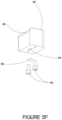
- FIGS 5A and 5B show the vacuum air supply port 57', drying air supply port 55' and solvent supply port 56', to supply vacuum air, drying air and solvent respectively to the cleaning and drying device 10.
- Vacuum air supply port 57' is in communication with vacuum channel 57 and vacuum outlet ports 58.
- Drying air supply port 55' is in communication with air conduit channel 55 and air supply aperture 64 and air block nozzle 65 of each air block 60 (see Figures 5E and 5F ).
- Solvent supply port 56' is in communication with solvent conduit channel 56 and solvent feed aperture 74 and solvent block nozzle 75 of each solvent block 70 ( Figures 5C and5D).
- Each solvent block receiver 71 and air block receiver 61 being separated by a wall.
- Each solvent block receiver 71 and air block receiver 61 have a solvent feed aperture 220 and air feed aperture 230, respectively, to feed solvent to a solvent block 70 (see Figures 5C and 5D ) and air to an air block 60 (see Figures 5E and 5F ).
- the lower portion of the upper plate 51 depicts a plurality of gasket channels to receive gaskets to keep air and solvent channels separate and avoid bleeding.
- each air block 60 is matingly received and fastened into a complementary air block receiver 61 with an air block fastener.
- the air block fastener is a pair of stainless steel socket cap screws 62 ( Figures 5E-5F ).
- Each solvent block 70 is matingly received and fastened into a complementary solvent block receiver 71 with a solvent block fastener.
- the solvent block fastener is a pair of stainless steel socket cap screws 72 ( Figures 5C-5D ).
- Each air block 60 is separated from each solvent block 70 by a separator wall 140 (although this is optional).
- the air blocks 60 and solvent blocks 70 could also be integral with the annular (ring shape) cap 50, the modularity of the blocks facilitates repair and replacement of each block, if required, without requiring replacement of the entire annular (ring shape) cap 50 and all blocks.
- Figures 5C and 5D depict solvent block 70 comprising a block shape with a solvent block channel 77 running along the inside of the solvent block 70 connecting the solvent feed aperture 74 on the annular ring 50 to the solvent block nozzle 75.
- solvent block nozzle 75 is matingly received into solvent block 70 via a recessed solvent block nozzle-receiving portion 76.
- a check ball 78 Between the solvent block nozzle receiving portion 76 and the solvent block nozzle 75 is a check ball 78 then a spring 79 against said check ball 78.
- the check ball 78 and spring 79 help maintain a seal when solvent flow is not needed.
- the solvent block channel-receiving portion 76 then receives a solvent nozzle seal, in this embodiment a solvent nozzle o-ring 78' to assist in ensuring solvent flow is restricted to the solvent block nozzle 75.
- a retainer plate 79' is provided to retain solvent block nozzle 75, solvent nozzle o-ring 78', spring 79 and solvent check ball 78 in said receiving portion 76.
- the retainer plate 79' is "C" shaped with a centrally located aperture allowing the nozzle 75 to perform as required.
- the retainer plate 79' is held in place with two stainless steel socket cap screws 77'.
- the solvent nozzle 75 has a solvent nozzle stream wall 75' which is angled based on the desired solvent spray pattern for certain applications.
- the angle of the solvent nozzle stream wall 75' may be, but not limited to, 0 to 90 degrees from centre, preferably from 30 to 60 degrees from centre.
- the solvent nozzle is adjustable and may be adjusted within the solvent block 70 to adjust solvent spray pattern as desired.
- volume of solvent may be controlled by orifice size in a flow restrictor which may be mounted proximate or at the solvent supply port 56' at the lower plate 52 of the cap 50.
- solvent supply port 56' may have a predetermined orifice size to control volume of solvent as desired.
- FIGS 5E and 5F depict air block 60 comprises a block shape with an air channel 63 connecting the air supply hole 64 on the annular (ring shape) cap 50 to the air block nozzle 65.
- Air block 60 is secured in place on upper plate 51 via two stainless steel socket cap screws 62.
- Air block nozzle 65 may be adjustable to modify air flow pattern and air flow volume as desired. Although the angle of air block nozzle 65 to air channel 63 is 90 degrees in this depiction, the angle may be adjusted to adjust flow direction and flow pattern as desired. Air nozzle angle may be, but not limited to, from 0 to 90 degrees from centre, preferably from 0 to 15 degrees from centre.
- Each solvent block 70 and air block 60 include a resilient o-ring gasket 66 for a tight seal against the upper plate 51 and minimize bleeding of air or solvent.
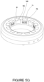
- Figure 5G depicts the annular ring (top cap) 50 when assembled with the alternating air blocks 60 and solvent blocks 70 secured in place.
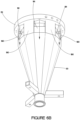
- FIG. 6A depicts the lower plate 52 attached to the second liner 40 via second liner fastener 41.
- second liner fastener 41 In this case two stainless steel cap screws fasten liner 40 to the bottom of the lower plate 52.
- lower plate 52 includes a hexagonal plate 180 on the bottom thereof that serves to engage with lower plate receiver 190 ( Figure 6B ) of the first liner 30.
- Each portion of the hexagonal plate 180 formed by a portion proximate each vertex 181 of the hexagonal plate 180 is received in each lower plate receiver 190.
- Each lower plate receiver 190 is formed by a portion of every other side of the dodecagonal shaped first liner 30. This provides a firm fit of the annular ring 50 with the first liner 30.
- Proximate each vertex of the hexagonal plate 180 is a vacuum air supply aperture to provide air into the housing such that a vacuum is created towards the bottom end of the unit, drawing solvent, air and any product or material cleaned off the cleaning unit.
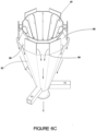
- Figure 6B depicts the first liner 30 fit over the second liner 40 (not seen).
- vacuum air is shown being blown downwards along the outside wall of the first liner at six locations 58 from the lower plate 52 (only three locations visible).
- Figures 6C , 6D and 6E depict the device showing air being directed towards the drain as well as vacuum air blowing downwards along the space formed by the inside wall of the housing and the outside wall of the first liner 30.
- air blown downwards between the first liner and the housing creates a vacuum effect (negative pressure) drawing air down through the second liner and up between the second and first liners.
- Heavy particulates 700 such as paint or the like removed from a spraying unit during the cleaning process and the solvent used in the process rotate and impact the inside wall and vanes of the second liner forming particulates 700.
- the additional corners and vanes in the second liner cause the liquids and VOCs to stop the rotation of the paint (impacting the velocity of paint removed from cap head and air stream) minimizing any VOCs, liquids and paint from moving upwards to the first liner and inside of the housing.
- These particulates 700 will fall to the bottom of the second liner towards the drain or will adhere to the inside of the second liner which may be easily cleaned at a later time.
- Any lighter particulates and vapourized solvent may be drawn upwards between the second and first liners and downwards between the first liner and housing to a scrubber, secondary waste recovery system or equivalent.
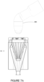
- FIGs 7A-7E there is depicted the cleaning and drying operation of a paint spraying unit 800 requiring cleaning.
- the paint spraying unit 800 is situated proximate the opening of the cleaning and drying device 10.
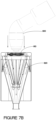
- the spraying unit 800 begins to be lowered into the opening with the solvent streams 810 and vacuum streams 820 actuated.
- the vacuum streams 820 create a vacuum by directing air downwards thus urging solvent to be directed towards the bottom of the device 10.
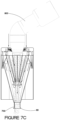
- the spraying unit 800 is partially lowered into the opening of the housing with the solvent spray cleaning the spraying unit and particulates 700 from the spraying unit 800 and solvent being directed downwards towards the drain 80.
- the solvent streams 810 is closed, the cleaned spraying unit 800 is raised upwards towards the top end and the air streams 830 is actuated to dry the cleaned spraying unit 800 and direct any solvent downwards towards the drain 80.
- the air streams 830 and vacuum streams 820 are closed. The spraying unit is not required to make direct contact with the cleaning and drying device 10.
- the second liner 40 with a plurality of elongated vertical vanes 400 connected to the inner wall of the second liner via vertical vane tabs 410 received in vane tab receivers 420 on said second liner (although the vanes may be integral with the second liner).
- removable vertical vanes 400 may be added along the inside wall of the second liner 40 to regulate speed (.e.g., slow down) of the air moving downwards along the inside of the second liner 40.
- the vertical vanes 400 may be from at least one, preferably a plurality, more preferably twelve, depending on the desired air flow control. If there are a plurality of vertical vanes, they are spaced apart from each other to facilitate air flow and speed control. Vertical vane length may vary depending on the desired condition.
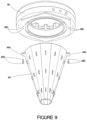
- FIG. 9 there is depicted a preferred connection of the second liner 40 to the bottom of the annular cap 50 via second liner screws 430 connecting two second liner tabs 440 extending radially outward from said second liner 40, to second liner screw apertures 450 on the bottom of the annular cap.
- This connection method facilitates removal if necessary as well as provides a secure connection (any suitable connection may be used).
- the first liner 30 is comprised by a number of walls forming a dodecagonal cone.
- each dodecagonal wall 310 comprises a top tab.
- Each dodecagonal wall alternates with a top tab in angle with the adjacent top tab.
- one dodecagonal wall 310 includes a vertically oriented top tab 320.
- the adjacent dodecagonal wall includes an inwardly angled top tab 330.
- every other top tab is vertically oriented to rest against a wall of the hexagonal housing 20, allowing for a point to connect and secure the first liner 30 with the housing 20. This point also serves to secure the annular cap to the housing (see Figures 10 and 11 ).
- the remaining top tabs are inwardly angled towards the centre of the first liner 30 forming a space along the length of the vertex of each wall of said housing 20.
- the remaining top tabs angled inward towards the centre of the first liner 30 also serve to hold the second liner 40 in place by a portion of the outer wall of the second liner 40 resting against the top edge of angled inward top tabs, as well as allow air flow as desired.
- the existing housing 930 and existing first liner 920 of the unit to be retrofitted will be used.
- an existing cap cleaner top cover 900 and inner liner 910 are removed.
- an existing cap cleaner retrofitted with the assembled cap 50 and second liner 40 allows the existing cap cleaner to have three different streams (solvent, air and vacuum) with the associated benefits described herein.
Description
- This disclosure relates to a device for cleaning and drying a spraying unit, in particular, for cleaning a paint-spraying unit. A component of the cleaning and drying device may also be retrofitted into existing cleaning and drying devices.
- Typical cleaning devices for cleaning a spraying unit include a single solvent stream and a single air stream. The solvent stream is used to remove unwanted material from the spraying unit and the air is used to assist in further removal of unwanted material and dry the cleaned spraying unit. In some instances, the exhaust from the cleaning devices comprise significant liquids and volatile organic compounds ("VOCs"). Some cleaning devices do not effectively clean and dry the spraying unit with water borne products on the spraying unit. Some cleaning devices experience residue caking on the inner walls thereof and retaining of dirt resulting in inefficiency of the cleaning devices as well as increased down time for maintenance and cleaning of the devices. In some instances, attempts to clean the cleaning devices of caked on residue and dirt further blocks the solvent recovery system of the cleaning devices. Existing/Currently available cleaning devices have stationary air outlets. There is a need for a cleaning and drying device that reduces residue caking. There is a need for a cleaning and drying device that includes directional and/or adjustable air outlets or air outlets that may accommodate varying air directions and/or flow pattern. There is a need for a cleaning and drying device that includes directional and/or adjustable solvent outlets or solvent outlets that may accommodate varying solvent directions and/or flow pattern. There is a need for a cleaning and drying device that reduces the potential of unwanted material to adhere to the outside surfaces as well as the exhaust passage and further areas that are inaccessible to cleaning a surface of a cleaning and drying device. There is a need for a cleaning and drying device which reduces liquids and VOCs from the exhaust thereof. There is a need for a component of a cleaning and drying device that may be retrofitted into existing cleaning/drying devices.
- Document
CN101537400 discloses a device for drying a spray gun used in an automatic manufactory. - The device is an effective two-stage solvent reclaiming system to lower cost in aspects of operation and environment. The device comprises a main body for accommodating a solvent spray head which is used for cleaning and inserted into the main body through non-contact seal, and an air spray head for cleaning an article once the article is cleaned. A low pressure area is generated in the main body by downwards guiding the air spray head so as to keep the air carried with a solvent in the main body. The air carried with the solvent is guided to a solvent separator positioned under the main body to reclaim the solvent.
- According to one aspect, there is provided a device for cleaning and drying a spraying unit, preferably a paint-spraying unit, more preferably a paint outlet of a paint spraying unit, according to claim 1.
- In one embodiment, said device comprises a plurality of vacuum air effluent ports.
- In another embodiment, said device comprises a plurality of drying air effluent ports.
- In another embodiment, said device comprises a plurality of solvent effluent ports.
- In an exemplary embodiment, said at least one air effluent port is proximate said annular (ring-shaped) cap.
- In an exemplary embodiment, said at least one solvent effluent port is proximate said annular (ring-shaped) cap.
- In an exemplary embodiment, each of said plurality of air effluent ports proximate said annular (ring-shaped) cap alternate with each of said plurality of solvent effluent ports proximate said annular (ring-shaped) cap; in exemplary embodiments, each of said plurality of air effluent ports are separated from each of said plurality of solvent effluent ports, by a wall;.
- In yet another embodiment, each of said plurality of air effluent ports proximate said annular (ring-shape) cap are above each of said plurality of solvent effluent ports proximate said annular (ring-shaped) cap.
- In yet another embodiment, each of said air effluent ports are contained within an air block such as a removable air block.
- In yet another embodiment, each of said solvent effluent ports are contained within a solvent block, preferably a removable solvent block.
- In an exemplary embodiment, said housing is hexagonal in shape.
- In an exemplary embodiment, said first liner is dodecagonal conical in shape.
- In an exemplary embodiment, said second liner is dodecagonal conical in shape.
- In exemplary embodiments, said dodecagonal conical in shape second liner further comprises at least one vane, preferably a plurality of spaced apart vanes, preferably vertically oriented along the inside of said inner wall of said second liner. Preferably said at least one vane, preferably said plurality of vanes, is a flat longitudinal shape.
- In another embodiment, at least one surface, preferably a plurality, of said device is smooth, for reducing adherence of unwanted product, solvent or combinations thereof to a surface of said device.
- In another embodiment, at least one surface, preferably a plurality, of said device is treated, for reducing adherence of unwanted product, solvent or combinations thereof to a surface of said device. In exemplary embodiments, said at least one surface is treated with Teflon™ or equivalent.
- In yet another embodiment, there is provided a cleaning, drying and vacuum element for use with an existing cleaning and drying device having an opening, said element comprising the features of claim 26.
- In exemplary embodiments, the material of construction of said device is selected from stainless steel, coated steel, aluminum and combinations thereof.
-
-
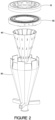
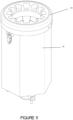
Figure 1 is a cross sectional view of the cleaning and drying device according to one embodiment. -
Figure 2 is an exploded view of the cleaning and drying device ofFigure 1 without the housing. -
Figure 3 is an exploded view of the cleaning and drying device ofFigure 1 without the annular (ring-shape) cap. -
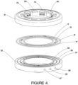
Figure 4 is an exploded view of the annular (ring-shape) cap with several components depicted according to one embodiment. -
Figure 5A is a top exploded view of the annular (ring-shape) cap according to one embodiment. -
Figure 5B is a bottom exploded view of the annular (ring-shape) cap according to one embodiment. -
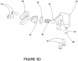
Figures 5C and5D are exploded views of the solvent block according to one embodiment. -
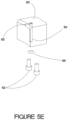
Figures 5E and5F are exploded views of the air block according to one embodiment. -
Figure 5G is a view of depicts the assembled annular cap ofFigures 4 ,5A - 5F . -
Figure 6A is a view of the second liner attached to the bottom plate of the annular (ring-shape) cap according to one embodiment. -
Figure 6B is a view of the first liner over the second liner attached to the bottom plate of the annular (ring-shape) cap according to one embodiment. -
Figure 6C is a view of the first and second liner and the air flow according to one embodiment. -
Figure 6D is a view of a cross section of the device with air flow lines according to one embodiment. -
Figure 6E is a view of the device without the cap with air flow lines according to one embodiment. -
Figures 7A-7E is a view of the sequence of the device when cleaning and drying a spraying unit according to one embodiment. -
Figure 8 is a view of the second liner with baffles (vanes) according to one embodiment. -
Figure 9 is a view of the connection of the second liner to the annular cap according to one embodiment. -
Figure 10 is a view of the connection of the first liner to the housing and the cap connectors according to one embodiment. -
Figure 11 is a view of the annular cap connected to the housing via cap connectors according to one embodiment. -
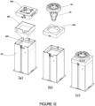
Figure 12 is a view of a retrofit system according to one embodiment. - Referring now to
Figure 1 , there is provided a cross section of the cleaning and drying device generally depicted as 10. The cleaning and dryingdevice 10 comprises ahousing 20 being a hexagonally shaped tube, afirst liner 30 being a dodecagonal shaped funnel within saidhousing 20, asecond liner 40 being a dodecagonal shaped funnel within saidfirst liner 30. Thehousing 20,first liner 30 andsecond liner 40 have at the top end thereof an annular (ring-shape)cap 50 with an opening for insertion and removal of a spraying unit (not shown) requiring cleaning and subsequent drying. The annular (ring shape)cap 50 includes a plurality of air blocks 60 andsolvent blocks 70 along the inner diameter thereof. In this embodiment, the air blocks 60 alternate with the solvent blocks 70, and each are separated from each other by a wall portion ofcap 50. Each ofsolvent blocks 70 provide solvent to the cleaning and dryingdevice 10, and in particular, in a direction and flow towards the centre of the opening formed by theannular ring 50 and towards the bottom of the cleaning and dryingdevice 10, in order to direct any unwanted product cleaned from the spraying unit (and used solvent) towards thedrain 80 of the first liner 30 (although the drain may be part of the second liner and/or the housing). Each of air blocks 60 provides drying air to the cleaning and dryingdevice 10, and in particular, in a direction and flow towards the centre of the opening and towards the bottom of the cleaning and dryingdevice 10 in order to dry the cleaned spraying unit and direct any residual unwanted product cleaned from the spraying unit and/or any residual solvent towards thedrain 80 of the first liner 30 (although the drain may be part of the second liner and/or the housing). The annular ring/cap 50, in this embodiment, comprises anupper plate 51 and alower plate 52.Upper plate 51 andlower plate 52 are fastened together with a plurality of plate fasteners, although any fastening method known to a person of ordinary skill may be used. In this instance, the plate fasteners are a series of stainless steelsocket cap screws 53 received incap screw receivers 54. Each ofcap screw receivers 54 have an upper plate portion and a lower plate portion.Upper plate 51 andlower plate 52, when fastened together, form a series of conduits (channels) running along the inside ofcap ring 50.Air conduit 55 serves to provide air to each of said air blocks 60.Solvent conduit 56 serves to provide solvent to each of said solvent blocks 70.Vacuum conduit 57 serves to provide vacuum air to eachvacuum air port 58. - Referring now to
Figure 2 , an exploded view of the cleaning and dryingdevice 10 showing theupper plate 51,lower plate 52,first liner 30 andsecond liner 40. In this embodiment, thefirst liner 30 andsecond liner 40 are cone-like and dodecagonal in shape. The cone-like shape denotes the smooth tapering from a top end to a bottom end, with each of thefirst liner 30 andsecond liner 40 tapering down towards thedrain 80. The dodecagonal shape denotes the shape of the walls of each of thefirst liner 30 and thesecond liner 40. - Referring now to
Figure 3 , an exploded view of the cleaning and dryingdevice 10 showing thehousing 20 along with thefirst liner 30 andsecond liner 40. In this embodiment, a plurality ofbase arms 90 located near thedrain 80 extend radially outward from thedrain 80. Eachbase arm 90 at an end distant thedrain 80, further comprises aleg 100 extending normally downward from eachbase arm 90 and parallel to a central axis of saiddrain 80. Eachleg 100 is held securely in place to saidrespective base arm 90 by aleg pin 110. Each end ofleg 100 distant thebase arm 90 fits into a leg end receiver (not shown) of a base (not shown). - Referring now to
Figures 4 ,5A and5B an exploded view of theannular ring 50 depicting theupper plate 51,lower plate 52,air conduit channel 55 for connecting to air supply port 55',solvent conduit channel 56 for connecting to solvent supply port 56',vacuum conduit channel 57 for connecting to vacuum supply port 57'. Eachchannel annular ring 50. To assist in preventing bleed over, a gasket, preferably a resilient gasket, preferably a plurality of gaskets, is provided between each channel. The gasket is secured in place when theupper plate 51 is secure to thelower plate 52. In this instance, first ring shapedgasket 11, maintains a seal betweenair conduit channel 55 and the opening of saiddevice 10; second ring shapedgasket 12, maintains a seal betweenair conduit channel 55 andsolvent conduit channel 56; third ring shapedgasket 13 maintains a seal betweensolvent conduit channel 56 and vacuumair conduit channel 57; and fourth ring shapedgasket 14 maintains a seal between vacuumair conduit channel 57 and the outside of saiddevice 10. Along the inner diameter of theannular ring 50 are the air blocks 60 alternating with the solvent blocks 70. -
Figures 5A and5B show the vacuum air supply port 57', drying air supply port 55' and solvent supply port 56', to supply vacuum air, drying air and solvent respectively to the cleaning and dryingdevice 10. Vacuum air supply port 57' is in communication withvacuum channel 57 andvacuum outlet ports 58. Drying air supply port 55' is in communication withair conduit channel 55 andair supply aperture 64 andair block nozzle 65 of each air block 60 (seeFigures 5E and5F ). Solvent supply port 56' is in communication withsolvent conduit channel 56 andsolvent feed aperture 74 andsolvent block nozzle 75 of each solvent block 70 (Figures 5C and5D). Also depicted are solvent block receivers 71to receivesolvent blocks 70 andair block receivers 61 to receive air blocks 60, alternating one with each other. Eachsolvent block receiver 71 andair block receiver 61 being separated by a wall. Eachsolvent block receiver 71 andair block receiver 61 have asolvent feed aperture 220 andair feed aperture 230, respectively, to feed solvent to a solvent block 70 (seeFigures 5C and5D ) and air to an air block 60 (seeFigures 5E and5F ). The lower portion of theupper plate 51 depicts a plurality of gasket channels to receive gaskets to keep air and solvent channels separate and avoid bleeding. - Referring now to
Figures 5A ,5C-5G , eachair block 60 is matingly received and fastened into a complementaryair block receiver 61 with an air block fastener. In this instance the air block fastener is a pair of stainless steel socket cap screws 62 (Figures 5E-5F ). Eachsolvent block 70 is matingly received and fastened into a complementarysolvent block receiver 71 with a solvent block fastener. In this instance the solvent block fastener is a pair of stainless steel socket cap screws 72 (Figures 5C-5D ). Eachair block 60 is separated from eachsolvent block 70 by a separator wall 140 (although this is optional). Although the air blocks 60 andsolvent blocks 70 could also be integral with the annular (ring shape)cap 50, the modularity of the blocks facilitates repair and replacement of each block, if required, without requiring replacement of the entire annular (ring shape)cap 50 and all blocks. -
Figures 5C and5D depictsolvent block 70 comprising a block shape with asolvent block channel 77 running along the inside of thesolvent block 70 connecting thesolvent feed aperture 74 on theannular ring 50 to thesolvent block nozzle 75. In a preferred embodiment,solvent block nozzle 75 is matingly received intosolvent block 70 via a recessed solvent block nozzle-receivingportion 76. Between the solvent blocknozzle receiving portion 76 and thesolvent block nozzle 75 is acheck ball 78 then aspring 79 against saidcheck ball 78. Thecheck ball 78 andspring 79 help maintain a seal when solvent flow is not needed. The solvent block channel-receivingportion 76 then receives a solvent nozzle seal, in this embodiment a solvent nozzle o-ring 78' to assist in ensuring solvent flow is restricted to thesolvent block nozzle 75. A retainer plate 79' is provided to retainsolvent block nozzle 75, solvent nozzle o-ring 78',spring 79 andsolvent check ball 78 in said receivingportion 76. The retainer plate 79' is "C" shaped with a centrally located aperture allowing thenozzle 75 to perform as required. The retainer plate 79' is held in place with two stainless steel socket cap screws 77'. Thesolvent nozzle 75 has a solvent nozzle stream wall 75' which is angled based on the desired solvent spray pattern for certain applications. For example, the angle of the solvent nozzle stream wall 75' may be, but not limited to, 0 to 90 degrees from centre, preferably from 30 to 60 degrees from centre. In an alternative embodiment, the solvent nozzle is adjustable and may be adjusted within thesolvent block 70 to adjust solvent spray pattern as desired. Further, volume of solvent may be controlled by orifice size in a flow restrictor which may be mounted proximate or at the solvent supply port 56' at thelower plate 52 of thecap 50. Alternatively solvent supply port 56' may have a predetermined orifice size to control volume of solvent as desired. -
Figures 5E and5F depictair block 60 comprises a block shape with anair channel 63 connecting theair supply hole 64 on the annular (ring shape)cap 50 to theair block nozzle 65.Air block 60 is secured in place onupper plate 51 via two stainless steel socket cap screws 62.Air block nozzle 65 may be adjustable to modify air flow pattern and air flow volume as desired. Although the angle ofair block nozzle 65 toair channel 63 is 90 degrees in this depiction, the angle may be adjusted to adjust flow direction and flow pattern as desired. Air nozzle angle may be, but not limited to, from 0 to 90 degrees from centre, preferably from 0 to 15 degrees from centre. - Each
solvent block 70 andair block 60 include a resilient o-ring gasket 66 for a tight seal against theupper plate 51 and minimize bleeding of air or solvent. -
Figure 5G depicts the annular ring (top cap) 50 when assembled with the alternating air blocks 60 andsolvent blocks 70 secured in place. -
Figure 6A depicts thelower plate 52 attached to thesecond liner 40 viasecond liner fastener 41. In this case two stainless steel cap screws fastenliner 40 to the bottom of thelower plate 52. As best seen inFigure 5B and6A ,lower plate 52 includes ahexagonal plate 180 on the bottom thereof that serves to engage with lower plate receiver 190 (Figure 6B ) of thefirst liner 30. Each portion of thehexagonal plate 180 formed by a portion proximate eachvertex 181 of thehexagonal plate 180 is received in eachlower plate receiver 190. Eachlower plate receiver 190 is formed by a portion of every other side of the dodecagonal shapedfirst liner 30. This provides a firm fit of theannular ring 50 with thefirst liner 30. Proximate each vertex of thehexagonal plate 180 is a vacuum air supply aperture to provide air into the housing such that a vacuum is created towards the bottom end of the unit, drawing solvent, air and any product or material cleaned off the cleaning unit. -
Figure 6B depicts thefirst liner 30 fit over the second liner 40 (not seen). In this figure, vacuum air is shown being blown downwards along the outside wall of the first liner at sixlocations 58 from the lower plate 52 (only three locations visible). -
Figures 6C ,6D and6E depict the device showing air being directed towards the drain as well as vacuum air blowing downwards along the space formed by the inside wall of the housing and the outside wall of thefirst liner 30. In this instance, air blown downwards between the first liner and the housing creates a vacuum effect (negative pressure) drawing air down through the second liner and up between the second and first liners.Heavy particulates 700 such as paint or the like removed from a spraying unit during the cleaning process and the solvent used in the process rotate and impact the inside wall and vanes of the secondliner forming particulates 700. The additional corners and vanes in the second liner cause the liquids and VOCs to stop the rotation of the paint (impacting the velocity of paint removed from cap head and air stream) minimizing any VOCs, liquids and paint from moving upwards to the first liner and inside of the housing. Theseparticulates 700 will fall to the bottom of the second liner towards the drain or will adhere to the inside of the second liner which may be easily cleaned at a later time. Any lighter particulates and vapourized solvent may be drawn upwards between the second and first liners and downwards between the first liner and housing to a scrubber, secondary waste recovery system or equivalent. - As best seen in
Figures 7A-7E , there is depicted the cleaning and drying operation of apaint spraying unit 800 requiring cleaning. InFigure 7A , thepaint spraying unit 800 is situated proximate the opening of the cleaning and dryingdevice 10. InFigure 7B , thespraying unit 800 begins to be lowered into the opening with the solvent streams 810 and vacuum streams 820 actuated. In this instance, the vacuum streams 820 create a vacuum by directing air downwards thus urging solvent to be directed towards the bottom of thedevice 10. InFigure 7C , thespraying unit 800 is partially lowered into the opening of the housing with the solvent spray cleaning the spraying unit andparticulates 700 from thespraying unit 800 and solvent being directed downwards towards thedrain 80. When the cleaning step is completed, the solvent streams 810 is closed, the cleaned sprayingunit 800 is raised upwards towards the top end and the air streams 830 is actuated to dry the cleaned sprayingunit 800 and direct any solvent downwards towards thedrain 80. When the cleaned and driedspraying unit 800 leaves the top end of the housing, the air streams 830 and vacuum streams 820 are closed. The spraying unit is not required to make direct contact with the cleaning and dryingdevice 10. - Referring now to
Figure 8 , there is depicted thesecond liner 40 with a plurality of elongatedvertical vanes 400 connected to the inner wall of the second liner viavertical vane tabs 410 received invane tab receivers 420 on said second liner (although the vanes may be integral with the second liner). In some instances, should vacuum control be required and/or desired, removablevertical vanes 400 may be added along the inside wall of thesecond liner 40 to regulate speed (.e.g., slow down) of the air moving downwards along the inside of thesecond liner 40. Thevertical vanes 400 may be from at least one, preferably a plurality, more preferably twelve, depending on the desired air flow control. If there are a plurality of vertical vanes, they are spaced apart from each other to facilitate air flow and speed control. Vertical vane length may vary depending on the desired condition. - Referring now to
Figure 9 , there is depicted a preferred connection of thesecond liner 40 to the bottom of theannular cap 50 via second liner screws 430 connecting twosecond liner tabs 440 extending radially outward from saidsecond liner 40, to secondliner screw apertures 450 on the bottom of the annular cap. This connection method facilitates removal if necessary as well as provides a secure connection (any suitable connection may be used). - Referring to
Figure 10 , there is depicted the connection mode of thefirst liner 30 to thehousing 20. As can be seen, thefirst liner 30 is comprised by a number of walls forming a dodecagonal cone. Proximate the top of thefirst liner 30, eachdodecagonal wall 310 comprises a top tab. Each dodecagonal wall alternates with a top tab in angle with the adjacent top tab. In particular, onedodecagonal wall 310 includes a vertically orientedtop tab 320. The adjacent dodecagonal wall includes an inwardly angledtop tab 330. In other words, every other top tab is vertically oriented to rest against a wall of thehexagonal housing 20, allowing for a point to connect and secure thefirst liner 30 with thehousing 20. This point also serves to secure the annular cap to the housing (seeFigures 10 and11 ). The remaining top tabs are inwardly angled towards the centre of thefirst liner 30 forming a space along the length of the vertex of each wall of saidhousing 20. The remaining top tabs angled inward towards the centre of thefirst liner 30 also serve to hold thesecond liner 40 in place by a portion of the outer wall of thesecond liner 40 resting against the top edge of angled inward top tabs, as well as allow air flow as desired. - Referring now to
Figure 12 , there is depicted the retrofitting of an existing cap cleaner 930 with theannular cap 50, =andsecond liner 40 disclosed herein. In this instance, the existing housing 930 and existingfirst liner 920 of the unit to be retrofitted will be used. As best seen inFigure 12(a) an existing cap cleanertop cover 900 andinner liner 910 are removed. As best see inFigure 12(b) keeping existingliner 920 in place,place retrofit lid 940 onto cap cleaner 930, adapted to accommodatehexagonal plate 180 ofcap 50 and as best seen inFigure 12(c) attach assembledcap 50 and second liner 40 (SeeFIG. 9 ) onto cap cleaner 930. Now an existing cap cleaner retrofitted with the assembledcap 50 andsecond liner 40 allows the existing cap cleaner to have three different streams (solvent, air and vacuum) with the associated benefits described herein.
Claims (26)
- A device for cleaning and drying a spraying unit, said device comprising:a top end and a bottom end;said top and said bottom end connected to each other by a housing (20);said housing (20) having an opening proximate said top end, for receiving at least a portion of said spraying unit,a first liner (30) within said housing (20),a second liner (40) within said first liner (30);said first liner (30) fitting within said housing (20) forming a space between an outside wall of said first liner (30) and an inside wall of said housing (20);a majority of said second liner (40) fitting within said first liner (30) forming a space between an outside wall of said second liner (40) and an inside wall of said first liner (30) and running a major length of said second liner (40);said opening further comprising an open annular cap (50), proximate the top end;said device having at least one vacuum air supply influent port, at least one drying air supply influent port and at least one solvent supply influent port, at least one vacuum air supply channel in communication with said at least one vacuum air supply influent port, for supplying vacuum air to at least one vacuum air effluent port (58); at least one drying air supply channel, in communication with said at least one drying air supply influent port, for supplying drying air to at least one drying air effluent port (65), said at least one drying air effluent port is adjustable in flow direction of said drying air; at least one solvent supply channel in communication with said at least one solvent supply influent port, for supplying solvent to at least one solvent effluent port (75);said at least one vacuum air effluent port flowing air downwards along the outside wall of said first liner (30), flowing in a direction away from said top end and towards said bottom end creating a vacuum within the device for drawing air through the top end of said device in a direction away from said top, down along an inside wall of said second liner (40) and upwards between the outside wall of said second liner (40) and inside wall of said first liner (30) and downwards along the outside wall of said first liner (30) drawing material and solvent towards and out a drain proximate said bottom end;said at least one drying air effluent port providing air proximate said opening of said housing (20), flowing air in a direction towards said bottom end; said at least one solvent effluent port (75) providing solvent proximate said top end of said device, flowing solvent in a direction towards said bottom end.
- The device of claim 1 further comprising a plurality of vacuum air effluent ports
- The device of claim 1 or 2 further comprising a plurality of drying air effluent ports.
- The device of any one of claims 1-3 further comprising a plurality of solvent effluent ports (75).
- The device of any one of claims 1-4 wherein said at least one drying air effluent port is proximate said open annular cap (50).
- The device of any one of claims 1-5 wherein said at least one solvent effluent port (75) is proximate said open annular cap (50)
- The device of claims 3 and 4 wherein each of said plurality of drying air effluent ports proximate said annular cap (50) alternates with each of said plurality of solvent effluent ports (75) proximate said open annular cap (50).
- The device of anyone of claims 1-7 wherein said housing (20) is hexagonal in shape.
- The device of any one of claims 1-8 wherein said first liner (30) is dodecagonal conical in shape.
- The device of any one of claims 1-9 wherein said second liner (40) is dodecagonal conical in shape.
- The device of claim 10 wherein said dodecagonal conical in shape second liner (40) further comprises at least one vane connected to the inner wall of said second liner (40)
- The device of claim 10 wherein said dodecagonal conical in shape second liner (40) further comprises a plurality of vanes connected to the inner wall of said second liner (40).
- The device of claim 11 wherein said at least one vane is vertically oriented along the inside of said inner wall of said second liner (40).
- The device of claim 12 wherein said plurality of vanes are vertically oriented along the inside of said inner wall of said second liner (40)
- The device of any one of claims 1-14 wherein at least one surface of said device is smooth, for reducing adherence of unwanted product, solvent or combinations thereof to a surface of said device.
- The device of any one of claims 1-14 wherein at least one surface of said device is treated, for reducing adherence of unwanted product, solvent or combinations thereof to a surface of said device.
- The device of claim 16 wherein said at least one surface is treated with Teflon.
- The device of any one of claims 1-14 wherein at least one surface, preferably a plurality, of said device is smooth and treated, for reducing adherence of unwanted product solvent or combinations thereof to a surface of said device.
- The device of any one of claims 1-18 wherein said device is selected from stainless steel, coated steel, aluminum and combinations thereof
- A method of cleaning and drying a spraying unit using a device of any one of claims 1-19, said method comprising:i) introducing a spraying unit to an opening of the device;ii) activating a vacuum air source and a solvent spray while moving the spraying unit downwards into the device;iii) assessing cleanliness of the spraying unit;iv) turning off the solvent spray;v) turning on the air spray; andvi) moving the spraying unit upwards to the opening.
- The device of claim 1 wherein said open cap (50) is an open annular cap (50) proximate a perimeter of said top end.
- The device of claim 1 wherein said at least one drying air effluent port is adjustable in flow direction of said drying air.
- The device of claim 1 wherein said at least one solvent effluent port (75) is adjustable in flow direction of said solvent.
- The device of claim 4 wherein said at least one solvent effluent port (75) is adjustable in volume of said solvent.
- The device of claim 1 wherein said at least one vacuum air effluent port provides air along the outside wall of said second liner (40), allows said air provided by said at least one vacuum air effluent port to flow in a direction away from said top end and towards said bottom end resulting in a vacuum within the device for drawing air through the top end of said device in a direction away from said top, down along the inside wall of said second liner (40); further draws air up through the space formed between the outside wall of said second liner (40) and inside wall of said first liner (30) and down through the space formed between the outside wall of said first liner (30) and inside wall of said housing (20) out through the bottom end of said device.
- A cleaning, drying and vacuum element for an existing cleaning and drying device having an opening, a top end and a bottom end, said element comprising:i) an open annular cap (50);ii) a cone shaped funnel attached to said open annular cap (50); said open annular cap (50) further comprising at least one vacuum air supply influent port, at least one drying air supply influent port and at least one solvent supply influent port, at least one vacuum air supply channel in communication with said at least one vacuum air supply influent port, for supplying vacuum air to at least one vacuum air effluent port (58); at least one drying air supply channel, in communication with said at least one drying air supply influent port, for supplying drying air to at least one drying air effluent port (65); said at least one drying air effluent port (65) is adjustable in flow direction of said drying air; at least one solvent supply channel in communication with said at least one solvent supply influent port, for supplying solvent to at least one solvent effluent port (75);said at least one vacuum air effluent port providing air to flow in a direction away from said open annular cap (50) and towards said bottom end of said existing cleaning and drying device resulting in a vacuum within the existing cleaning and drying device drawing air through said top end of said existing cleaning and drying device in a direction away from said top end, down along an inside wall of said cone shaped funnel drawing material and solvent towards and out a drain proximate said bottom end of said existing cleaning and drying device;said at least one drying air effluent port providing air proximate said opening of said existing cleaning and drying device, flowing air to flow in a direction towards said bottom end of said existing cleaning and drying device;said at least one solvent effluent port (75) providing solvent proximate said top end of said existing cleaning and drying device, flowing solvent in a direction towards said bottom end, said top end and said bottom end connected to each other by a housing (20);said cone shaped funnel comprising a first liner (30) of dodecagonal shaped funnel and a second liner (40) of dodecagonal shaped funnel;said second liner (40) further comprising a plurality of spaced apart elongated vertical vanes (400); wherein a majority of said second liner (40) fitting within said first liner (30) forming a space between an outside wall of said second liner (40) and an inside wall of said first liner (30) and running a major length of said second liner (40).
Applications Claiming Priority (1)
| Application Number | Priority Date | Filing Date | Title |
|---|---|---|---|
| PCT/CA2016/051455 WO2018102907A1 (en) | 2016-12-09 | 2016-12-09 | Device for cleaning and drying a spraying unit |
Publications (3)
| Publication Number | Publication Date |
|---|---|
| EP3551346A1 EP3551346A1 (en) | 2019-10-16 |
| EP3551346A4 EP3551346A4 (en) | 2020-08-05 |
| EP3551346B1 true EP3551346B1 (en) | 2023-07-12 |
Family
ID=62490593
Family Applications (1)
| Application Number | Title | Priority Date | Filing Date |
|---|---|---|---|
| EP16923141.2A Active EP3551346B1 (en) | 2016-12-09 | 2016-12-09 | Device for cleaning and drying a spraying unit |
Country Status (6)
| Country | Link |
|---|---|
| US (1) | US11253884B2 (en) |
| EP (1) | EP3551346B1 (en) |
| JP (1) | JP6913403B2 (en) |
| CN (1) | CN110072634B (en) |
| CA (1) | CA3045047C (en) |
| WO (1) | WO2018102907A1 (en) |
Families Citing this family (6)
| Publication number | Priority date | Publication date | Assignee | Title |
|---|---|---|---|---|
| US11097301B2 (en) | 2016-11-17 | 2021-08-24 | Happy Dynamics Inc. | Apparatus for a low pressure non-contact cleaning of a paint applicator |
| KR102532733B1 (en) * | 2018-02-14 | 2023-05-16 | 삼성디스플레이 주식회사 | Particle removal apparatus and laser cutting apparatus including the same |
| CN110586395B (en) * | 2019-09-12 | 2020-12-25 | 四川富生电器有限责任公司 | Anti-adhesion motor wire-inserting lubricating oil spray head structure |
| TWI715369B (en) * | 2019-12-24 | 2021-01-01 | 萬潤科技股份有限公司 | Liquid absorption component, liquid material receiving method and device |
| CN112547393B (en) * | 2020-11-30 | 2022-03-11 | 浙江瑞丰五福气动工具有限公司 | Pneumatic spray gun paint spraying workbench |
| CN115502011B (en) * | 2022-10-18 | 2023-07-21 | 东莞鹏龙光电有限公司 | A intelligent production equipment for producing display module assembly |
Family Cites Families (13)
| Publication number | Priority date | Publication date | Assignee | Title |
|---|---|---|---|---|
| SE447799B (en) | 1986-01-20 | 1986-12-15 | Stern Leif Einar | DEVICE FOR SPRAGING PISTOLS RENGORA FARM DISTRIBUTION CHANNELS |
| US5174317A (en) * | 1986-09-05 | 1992-12-29 | Herkules Equipment Corporation | Spray gun and associate parts washer and recycler |
| DE3808801A1 (en) * | 1988-03-16 | 1989-10-05 | Behr Industrieanlagen | METHOD AND DEVICE FOR CLEANING A SPRAYING DEVICE |
| US4934393A (en) | 1988-06-30 | 1990-06-19 | John S. Lighthall | Spray gun cleaning apparatus |
| US5693150A (en) * | 1996-05-03 | 1997-12-02 | Aeg Automation Systems Corporation | Automatic paint gun cleaner |
| CN2538433Y (en) | 2002-02-21 | 2003-03-05 | 洽昌工业股份有限公司 | Automatic washing device for paint spray pistol |
| JP4511371B2 (en) * | 2003-02-21 | 2010-07-28 | ジュサップ,フィリップ | Non-contact spray equipment cleaning device |
| US7597767B1 (en) * | 2005-03-31 | 2009-10-06 | Honda Motor Co., Ltd. | Paint gun cleaning apparatus |
| CN101537400B (en) * | 2008-03-18 | 2013-11-06 | 菲利普·约瑟夫 | Cleaning device for paint spraying apparatus |
| US9221068B2 (en) * | 2013-10-09 | 2015-12-29 | Philip Jessup | Apparatus for non-contact cleaning a paint spray tip |
| CN105127037A (en) * | 2015-07-17 | 2015-12-09 | 深圳市泰达机器人有限公司 | Full-automatic cleaning device of spraying tool |
| US11097301B2 (en) * | 2016-11-17 | 2021-08-24 | Happy Dynamics Inc. | Apparatus for a low pressure non-contact cleaning of a paint applicator |
| EP3356054B1 (en) * | 2016-11-22 | 2020-02-19 | Crystal CAP Cleaners Inc. | Improved apparatus for cleaning spray guns and bells |
-
2016
- 2016-12-09 CA CA3045047A patent/CA3045047C/en active Active
- 2016-12-09 EP EP16923141.2A patent/EP3551346B1/en active Active
- 2016-12-09 US US16/466,189 patent/US11253884B2/en active Active
- 2016-12-09 JP JP2019530653A patent/JP6913403B2/en active Active
- 2016-12-09 WO PCT/CA2016/051455 patent/WO2018102907A1/en unknown
- 2016-12-09 CN CN201680091436.3A patent/CN110072634B/en active Active
Also Published As
| Publication number | Publication date |
|---|---|
| CN110072634A (en) | 2019-07-30 |
| JP2020503168A (en) | 2020-01-30 |
| EP3551346A4 (en) | 2020-08-05 |
| EP3551346A1 (en) | 2019-10-16 |
| WO2018102907A1 (en) | 2018-06-14 |
| US11253884B2 (en) | 2022-02-22 |
| CN110072634B (en) | 2022-02-22 |
| US20200147633A1 (en) | 2020-05-14 |
| CA3045047A1 (en) | 2018-06-14 |
| CA3045047C (en) | 2023-08-29 |
| JP6913403B2 (en) | 2021-08-04 |
Similar Documents
| Publication | Publication Date | Title |
|---|---|---|
| EP3551346B1 (en) | Device for cleaning and drying a spraying unit | |
| CN108323161B (en) | Improved device for cleaning spray gun | |
| JP5721084B2 (en) | Equipment for processing workpieces for microelectronics | |
| CA2910690C (en) | Laminar water fountain | |
| US10561973B2 (en) | Element assembly and filter | |
| US7954446B2 (en) | Hopper for cleaning coating machine | |
| JP2015020129A (en) | Dust collecting apparatus for painting system | |
| CN112044652A (en) | Special device for cleaning spraying atomizer | |
| CN208627642U (en) | Dust removal showerhead for outdoor building yard | |
| KR101784210B1 (en) | Air Distributor with Centrifuge Functioning of Condensed Water | |
| KR101596930B1 (en) | A washing apparatus | |
| US9827576B2 (en) | Nozzle assembly capable of performing suction and high pressure blowing | |
| RU2727626C1 (en) | Varnishing and painting installation, part varnish-and-paint finishing method and filtering element for them | |
| EP1800761B1 (en) | Spraying and atomatization device of a saline mixture | |
| CN212493627U (en) | Special device for cleaning spraying atomizer | |
| WO2019132661A1 (en) | Washing device for washing objects, and sprayer, conversion kit and method therefor | |
| US7597767B1 (en) | Paint gun cleaning apparatus | |
| CN211217881U (en) | Dust remover with ash removal device | |
| KR20080002852U (en) | Nozzle for fire-extinguisher | |
| SG10201802425VA (en) | Self-cleaning discard cyclone separator system | |
| CN106000734A (en) | Paint recovery device | |
| CN105499026A (en) | Paint spraying device of flange pipe fitting | |
| MX2012014501A (en) | Water shower with turbine system. | |
| JP2014223601A (en) | Waste liquid recovery apparatus and method |
Legal Events
| Date | Code | Title | Description |
|---|---|---|---|
| STAA | Information on the status of an ep patent application or granted ep patent |
Free format text: STATUS: THE INTERNATIONAL PUBLICATION HAS BEEN MADE |
|
| PUAI | Public reference made under article 153(3) epc to a published international application that has entered the european phase |
Free format text: ORIGINAL CODE: 0009012 |
|
| STAA | Information on the status of an ep patent application or granted ep patent |
Free format text: STATUS: REQUEST FOR EXAMINATION WAS MADE |
|
| 17P | Request for examination filed |
Effective date: 20190529 |
|
| AK | Designated contracting states |
Kind code of ref document: A1 Designated state(s): AL AT BE BG CH CY CZ DE DK EE ES FI FR GB GR HR HU IE IS IT LI LT LU LV MC MK MT NL NO PL PT RO RS SE SI SK SM TR |
|
| AX | Request for extension of the european patent |
Extension state: BA ME |
|
| DAV | Request for validation of the european patent (deleted) | ||
| DAX | Request for extension of the european patent (deleted) | ||
| A4 | Supplementary search report drawn up and despatched |
Effective date: 20200702 |
|
| RIC1 | Information provided on ipc code assigned before grant |
Ipc: B05B 15/50 20180101AFI20200626BHEP Ipc: B05B 14/49 20180101ALI20200626BHEP Ipc: B05B 15/555 20180101ALI20200626BHEP Ipc: B08B 15/02 20060101ALI20200626BHEP |
|
| STAA | Information on the status of an ep patent application or granted ep patent |
Free format text: STATUS: EXAMINATION IS IN PROGRESS |
|
| 17Q | First examination report despatched |
Effective date: 20220803 |
|
| GRAP | Despatch of communication of intention to grant a patent |
Free format text: ORIGINAL CODE: EPIDOSNIGR1 |
|
| STAA | Information on the status of an ep patent application or granted ep patent |
Free format text: STATUS: GRANT OF PATENT IS INTENDED |
|
| INTG | Intention to grant announced |
Effective date: 20230214 |
|
| RIN1 | Information on inventor provided before grant (corrected) |
Inventor name: DOYLE, JAMES LAURENCE |
|
| GRAS | Grant fee paid |
Free format text: ORIGINAL CODE: EPIDOSNIGR3 |
|
| GRAA | (expected) grant |
Free format text: ORIGINAL CODE: 0009210 |
|
| STAA | Information on the status of an ep patent application or granted ep patent |
Free format text: STATUS: THE PATENT HAS BEEN GRANTED |
|
| AK | Designated contracting states |
Kind code of ref document: B1 Designated state(s): AL AT BE BG CH CY CZ DE DK EE ES FI FR GB GR HR HU IE IS IT LI LT LU LV MC MK MT NL NO PL PT RO RS SE SI SK SM TR |
|
| REG | Reference to a national code |
Ref country code: CH Ref legal event code: EP |
|
| REG | Reference to a national code |
Ref country code: DE Ref legal event code: R096 Ref document number: 602016081083 Country of ref document: DE |
|
| REG | Reference to a national code |
Ref country code: IE Ref legal event code: FG4D |
|
| REG | Reference to a national code |
Ref country code: LT Ref legal event code: MG9D |
|
| P01 | Opt-out of the competence of the unified patent court (upc) registered |
Effective date: 20231005 |
|
| REG | Reference to a national code |
Ref country code: NL Ref legal event code: MP Effective date: 20230712 |
|
| REG | Reference to a national code |
Ref country code: AT Ref legal event code: MK05 Ref document number: 1586545 Country of ref document: AT Kind code of ref document: T Effective date: 20230712 |
|
| PG25 | Lapsed in a contracting state [announced via postgrant information from national office to epo] |
Ref country code: NL Free format text: LAPSE BECAUSE OF FAILURE TO SUBMIT A TRANSLATION OF THE DESCRIPTION OR TO PAY THE FEE WITHIN THE PRESCRIBED TIME-LIMIT Effective date: 20230712 |
|
| PG25 | Lapsed in a contracting state [announced via postgrant information from national office to epo] |
Ref country code: GR Free format text: LAPSE BECAUSE OF FAILURE TO SUBMIT A TRANSLATION OF THE DESCRIPTION OR TO PAY THE FEE WITHIN THE PRESCRIBED TIME-LIMIT Effective date: 20231013 |
|
| PGFP | Annual fee paid to national office [announced via postgrant information from national office to epo] |
Ref country code: GB Payment date: 20231222 Year of fee payment: 8 |
|
| PG25 | Lapsed in a contracting state [announced via postgrant information from national office to epo] |
Ref country code: ES Free format text: LAPSE BECAUSE OF FAILURE TO SUBMIT A TRANSLATION OF THE DESCRIPTION OR TO PAY THE FEE WITHIN THE PRESCRIBED TIME-LIMIT Effective date: 20230712 |
|
| PG25 | Lapsed in a contracting state [announced via postgrant information from national office to epo] |
Ref country code: IS Free format text: LAPSE BECAUSE OF FAILURE TO SUBMIT A TRANSLATION OF THE DESCRIPTION OR TO PAY THE FEE WITHIN THE PRESCRIBED TIME-LIMIT Effective date: 20231112 |
|
| PG25 | Lapsed in a contracting state [announced via postgrant information from national office to epo] |
Ref country code: SE Free format text: LAPSE BECAUSE OF FAILURE TO SUBMIT A TRANSLATION OF THE DESCRIPTION OR TO PAY THE FEE WITHIN THE PRESCRIBED TIME-LIMIT Effective date: 20230712 Ref country code: RS Free format text: LAPSE BECAUSE OF FAILURE TO SUBMIT A TRANSLATION OF THE DESCRIPTION OR TO PAY THE FEE WITHIN THE PRESCRIBED TIME-LIMIT Effective date: 20230712 Ref country code: PT Free format text: LAPSE BECAUSE OF FAILURE TO SUBMIT A TRANSLATION OF THE DESCRIPTION OR TO PAY THE FEE WITHIN THE PRESCRIBED TIME-LIMIT Effective date: 20231113 Ref country code: NO Free format text: LAPSE BECAUSE OF FAILURE TO SUBMIT A TRANSLATION OF THE DESCRIPTION OR TO PAY THE FEE WITHIN THE PRESCRIBED TIME-LIMIT Effective date: 20231012 Ref country code: LV Free format text: LAPSE BECAUSE OF FAILURE TO SUBMIT A TRANSLATION OF THE DESCRIPTION OR TO PAY THE FEE WITHIN THE PRESCRIBED TIME-LIMIT Effective date: 20230712 Ref country code: LT Free format text: LAPSE BECAUSE OF FAILURE TO SUBMIT A TRANSLATION OF THE DESCRIPTION OR TO PAY THE FEE WITHIN THE PRESCRIBED TIME-LIMIT Effective date: 20230712 Ref country code: IS Free format text: LAPSE BECAUSE OF FAILURE TO SUBMIT A TRANSLATION OF THE DESCRIPTION OR TO PAY THE FEE WITHIN THE PRESCRIBED TIME-LIMIT Effective date: 20231112 Ref country code: HR Free format text: LAPSE BECAUSE OF FAILURE TO SUBMIT A TRANSLATION OF THE DESCRIPTION OR TO PAY THE FEE WITHIN THE PRESCRIBED TIME-LIMIT Effective date: 20230712 Ref country code: GR Free format text: LAPSE BECAUSE OF FAILURE TO SUBMIT A TRANSLATION OF THE DESCRIPTION OR TO PAY THE FEE WITHIN THE PRESCRIBED TIME-LIMIT Effective date: 20231013 Ref country code: FI Free format text: LAPSE BECAUSE OF FAILURE TO SUBMIT A TRANSLATION OF THE DESCRIPTION OR TO PAY THE FEE WITHIN THE PRESCRIBED TIME-LIMIT Effective date: 20230712 Ref country code: ES Free format text: LAPSE BECAUSE OF FAILURE TO SUBMIT A TRANSLATION OF THE DESCRIPTION OR TO PAY THE FEE WITHIN THE PRESCRIBED TIME-LIMIT Effective date: 20230712 Ref country code: AT Free format text: LAPSE BECAUSE OF FAILURE TO SUBMIT A TRANSLATION OF THE DESCRIPTION OR TO PAY THE FEE WITHIN THE PRESCRIBED TIME-LIMIT Effective date: 20230712 |
|
| PGFP | Annual fee paid to national office [announced via postgrant information from national office to epo] |
Ref country code: FR Payment date: 20231222 Year of fee payment: 8 |
|
| PG25 | Lapsed in a contracting state [announced via postgrant information from national office to epo] |
Ref country code: PL Free format text: LAPSE BECAUSE OF FAILURE TO SUBMIT A TRANSLATION OF THE DESCRIPTION OR TO PAY THE FEE WITHIN THE PRESCRIBED TIME-LIMIT Effective date: 20230712 |