EP3551141B1 - Dispositif destiné à l'application externe d'une force de pression locale en dessous de l'arc costal d'un patient destinée à la réduction du volume de l'estomac - Google Patents
Dispositif destiné à l'application externe d'une force de pression locale en dessous de l'arc costal d'un patient destinée à la réduction du volume de l'estomac Download PDFInfo
- Publication number
- EP3551141B1 EP3551141B1 EP17822184.2A EP17822184A EP3551141B1 EP 3551141 B1 EP3551141 B1 EP 3551141B1 EP 17822184 A EP17822184 A EP 17822184A EP 3551141 B1 EP3551141 B1 EP 3551141B1
- Authority
- EP
- European Patent Office
- Prior art keywords
- pressure
- patient
- belt
- pressure body
- area
- Prior art date
- Legal status (The legal status is an assumption and is not a legal conclusion. Google has not performed a legal analysis and makes no representation as to the accuracy of the status listed.)
- Active
Links
- 210000002784 stomach Anatomy 0.000 title claims description 46
- QTCANKDTWWSCMR-UHFFFAOYSA-N costic aldehyde Natural products C1CCC(=C)C2CC(C(=C)C=O)CCC21C QTCANKDTWWSCMR-UHFFFAOYSA-N 0.000 title claims description 18
- ISTFUJWTQAMRGA-UHFFFAOYSA-N iso-beta-costal Natural products C1C(C(=C)C=O)CCC2(C)CCCC(C)=C21 ISTFUJWTQAMRGA-UHFFFAOYSA-N 0.000 title claims description 18
- 230000003014 reinforcing effect Effects 0.000 claims description 47
- 239000000463 material Substances 0.000 claims description 22
- 239000004033 plastic Substances 0.000 claims description 6
- 229920001296 polysiloxane Polymers 0.000 claims description 5
- 210000003484 anatomy Anatomy 0.000 claims description 4
- 210000003205 muscle Anatomy 0.000 claims description 4
- 239000008280 blood Substances 0.000 claims description 3
- 210000004369 blood Anatomy 0.000 claims description 3
- 230000036772 blood pressure Effects 0.000 claims description 3
- 230000036760 body temperature Effects 0.000 claims description 3
- 239000013013 elastic material Substances 0.000 claims description 3
- XLYOFNOQVPJJNP-UHFFFAOYSA-N water Substances O XLYOFNOQVPJJNP-UHFFFAOYSA-N 0.000 claims description 3
- 230000005540 biological transmission Effects 0.000 claims description 2
- 239000004744 fabric Substances 0.000 claims description 2
- 230000036387 respiratory rate Effects 0.000 claims description 2
- 238000011161 development Methods 0.000 description 11
- 238000013459 approach Methods 0.000 description 5
- 238000013461 design Methods 0.000 description 4
- 235000003642 hunger Nutrition 0.000 description 4
- 238000003825 pressing Methods 0.000 description 4
- 206010033307 Overweight Diseases 0.000 description 3
- 239000011248 coating agent Substances 0.000 description 3
- 238000000576 coating method Methods 0.000 description 3
- 239000003814 drug Substances 0.000 description 3
- 229940079593 drug Drugs 0.000 description 3
- 210000000056 organ Anatomy 0.000 description 3
- 238000002560 therapeutic procedure Methods 0.000 description 3
- 208000008589 Obesity Diseases 0.000 description 2
- 210000001015 abdomen Anatomy 0.000 description 2
- 210000000683 abdominal cavity Anatomy 0.000 description 2
- 230000006835 compression Effects 0.000 description 2
- 238000007906 compression Methods 0.000 description 2
- 235000005911 diet Nutrition 0.000 description 2
- 230000000378 dietary effect Effects 0.000 description 2
- 238000011038 discontinuous diafiltration by volume reduction Methods 0.000 description 2
- 230000000694 effects Effects 0.000 description 2
- 238000011156 evaluation Methods 0.000 description 2
- 230000002496 gastric effect Effects 0.000 description 2
- 210000000936 intestine Anatomy 0.000 description 2
- 239000002184 metal Substances 0.000 description 2
- 235000020824 obesity Nutrition 0.000 description 2
- 230000001603 reducing effect Effects 0.000 description 2
- 238000001356 surgical procedure Methods 0.000 description 2
- 208000031872 Body Remains Diseases 0.000 description 1
- 206010040880 Skin irritation Diseases 0.000 description 1
- 230000003187 abdominal effect Effects 0.000 description 1
- 230000036528 appetite Effects 0.000 description 1
- 235000019789 appetite Nutrition 0.000 description 1
- 210000003451 celiac plexus Anatomy 0.000 description 1
- 230000006378 damage Effects 0.000 description 1
- 230000003670 easy-to-clean Effects 0.000 description 1
- 230000020595 eating behavior Effects 0.000 description 1
- 239000006260 foam Substances 0.000 description 1
- 230000037406 food intake Effects 0.000 description 1
- 235000012631 food intake Nutrition 0.000 description 1
- 210000001035 gastrointestinal tract Anatomy 0.000 description 1
- 208000030159 metabolic disease Diseases 0.000 description 1
- 238000012544 monitoring process Methods 0.000 description 1
- 230000000399 orthopedic effect Effects 0.000 description 1
- 230000002787 reinforcement Effects 0.000 description 1
- 230000029058 respiratory gaseous exchange Effects 0.000 description 1
- 238000007493 shaping process Methods 0.000 description 1
- 230000036556 skin irritation Effects 0.000 description 1
- 231100000475 skin irritation Toxicity 0.000 description 1
- 239000004753 textile Substances 0.000 description 1
- 229920001169 thermoplastic Polymers 0.000 description 1
- 239000012815 thermoplastic material Substances 0.000 description 1
- 239000004416 thermosoftening plastic Substances 0.000 description 1
- 238000009423 ventilation Methods 0.000 description 1
- 238000004260 weight control Methods 0.000 description 1
Images


Classifications
-
- A—HUMAN NECESSITIES
- A61—MEDICAL OR VETERINARY SCIENCE; HYGIENE
- A61F—FILTERS IMPLANTABLE INTO BLOOD VESSELS; PROSTHESES; DEVICES PROVIDING PATENCY TO, OR PREVENTING COLLAPSING OF, TUBULAR STRUCTURES OF THE BODY, e.g. STENTS; ORTHOPAEDIC, NURSING OR CONTRACEPTIVE DEVICES; FOMENTATION; TREATMENT OR PROTECTION OF EYES OR EARS; BANDAGES, DRESSINGS OR ABSORBENT PADS; FIRST-AID KITS
- A61F5/00—Orthopaedic methods or devices for non-surgical treatment of bones or joints; Nursing devices; Anti-rape devices
- A61F5/0003—Apparatus for the treatment of obesity; Anti-eating devices
- A61F5/0009—External belts
-
- A—HUMAN NECESSITIES
- A61—MEDICAL OR VETERINARY SCIENCE; HYGIENE
- A61B—DIAGNOSIS; SURGERY; IDENTIFICATION
- A61B5/00—Measuring for diagnostic purposes; Identification of persons
- A61B5/0002—Remote monitoring of patients using telemetry, e.g. transmission of vital signals via a communication network
- A61B5/0015—Remote monitoring of patients using telemetry, e.g. transmission of vital signals via a communication network characterised by features of the telemetry system
- A61B5/0017—Remote monitoring of patients using telemetry, e.g. transmission of vital signals via a communication network characterised by features of the telemetry system transmitting optical signals
-
- A—HUMAN NECESSITIES
- A61—MEDICAL OR VETERINARY SCIENCE; HYGIENE
- A61B—DIAGNOSIS; SURGERY; IDENTIFICATION
- A61B5/00—Measuring for diagnostic purposes; Identification of persons
- A61B5/48—Other medical applications
- A61B5/4836—Diagnosis combined with treatment in closed-loop systems or methods
-
- A—HUMAN NECESSITIES
- A61—MEDICAL OR VETERINARY SCIENCE; HYGIENE
- A61F—FILTERS IMPLANTABLE INTO BLOOD VESSELS; PROSTHESES; DEVICES PROVIDING PATENCY TO, OR PREVENTING COLLAPSING OF, TUBULAR STRUCTURES OF THE BODY, e.g. STENTS; ORTHOPAEDIC, NURSING OR CONTRACEPTIVE DEVICES; FOMENTATION; TREATMENT OR PROTECTION OF EYES OR EARS; BANDAGES, DRESSINGS OR ABSORBENT PADS; FIRST-AID KITS
- A61F5/00—Orthopaedic methods or devices for non-surgical treatment of bones or joints; Nursing devices; Anti-rape devices
- A61F5/01—Orthopaedic devices, e.g. splints, casts or braces
- A61F5/03—Corsets or bandages for abdomen, teat or breast support, with or without pads
Definitions
- the present invention relates to a device for externally applying a local pressure force below the costal arch of a patient to reduce the volume of the stomach.
- the treatment of overweight people who suffer from metabolic diseases or obesity is becoming increasingly important.
- One approach to this treatment is to reduce a patient's stomach volume.
- there are particularly invasive or surgical forms of treatment such as applying a gastric band, surgically performing a stomach reduction or inserting a gastric balloon.
- Surgical forms of treatment usually lead to a certain degree of success in the short term and at least temporarily, but they cannot be carried out as often as desired in patients who repeatedly tend to be overweight, usually only a few times. For example, a patient can usually only undergo a stomach reduction once.
- surgical forms of treatment bring with them the well-known side effects of a surgical procedure, so that these forms of treatment are not an option for all patients.
- surgical procedures are costly and pose a risk to the patient.
- Drug treatment approaches usually have significant side effects that put unnecessary strain on the patient's organism.
- US 7,264,600 B2 describes an active belt for weight control. This can be used to specifically inflate air cushions. It also describes a type of massage function.
- DE 102 07 887 A1 discloses a device in which a pressure application can be generated pneumatically or hydraulically in the stomach area from the outside.
- US 2,671,899 is considered the closest prior art and discloses a device for achieving an increase in pressure in the epigastric region of a patient, wherein a hollow body attached to a belt is provided, which is formed with individual ventilation openings and is intended to exert pressure on the epigastric region.
- WO 2010/042080 A1 describes a corset that, on the one hand, is intended to improve the external appearance of a patient through shaping and, on the other hand, to curb a patient's appetite by specifically applying pressure to the stomach area.
- DE 198 22 221 A1 discloses another device for applying pressure to the stomach region of a patient with various padding elements.
- US 3,578,773 A discloses an orthopedic belt with a pressure body, wherein targeted pressure is applied to specific muscles, injuries or weakened areas of a patient's upper body.
- the present invention is based on the object of providing a device which is suitable for reducing the size of a patient's stomach.
- the inventor has recognized that it is fundamentally possible to permanently reduce the stomach volume of a patient by applying a pressure force to the patient's body in the area of the stomach area from the outside and thus reduce the patient's feeling of hunger.
- the elastic belt which is under tension, is placed around the patient's upper body in the area of the costal arch.
- the compressive force exerted in the radial direction by the elastic tension of the belt on the patient's upper body is at least partially concentrated at points or locally via the pressure body on the area of the stomach area and a pressure force is thus permanently exerted on the patient's stomach area.
- the pressure body with its geometry tailored to the patient's costal arch, nestles into it and thus applies the pressure force there.
- the pressure body is designed in the form of a negative impression of the rib arch.
- the pressure body causes compression of the upper abdomen in the area of the epigastrium (stomach), whereby the air in the stomach is compressed or squeezed out and the stomach volume is permanently reduced and restricted.
- the organs in the abdominal cavity lie in an airless space (vacuum) and the stomach and intestines are the only organs that can contain air. Pressure applied to the abdominal cavity is therefore transmitted directly to the stomach and intestines and leads to volume reduction at the desired location.
- the device according to the invention can be used to achieve a permanent and constant volume reduction by means of moderate but continuous compression on the stomach, which has a reducing effect on the patient's feeling of hunger and eating behavior.
- a reduction in the stomach volume can be achieved conservatively, ie without surgical or medical intervention, so that the patient feels less hunger and will therefore reduce his excess weight over time due to lower food intake.
- the elastic belt is closed or is designed in the form of an at least partially elastic band, which can be adjustably connected to one another in the area of its ends via connecting means for adjusting its effective length around the patient's upper body.
- the belt is closed, it is preferably offered in different sizes so that it can be used by patients with different body sizes.
- an open, band-shaped belt is preferably used, which can be closed at its ends with connecting means.
- the connecting means are designed in the form of a Velcro fastener, with a flat Velcro area preferably being provided at one end and a flat Velcro hook area being provided at the other end, or the connecting means being in the form of at least one adjustable closure element, such as at least a belt-buckle connection or a rotary locking mechanism or locking mechanism or the like.
- the belt can be adapted to any patient, with different belt lengths preferably being offered as basic sizes.
- the pressure body is designed in the form of a flat, flexible pressure body.
- the pressure body can in particular be designed in the form of a rubber, plastic or silicone body.
- the pressure body is designed in such a way that it is suitable for attacking below the costal arch, i.e. H. in such a way that the pressure body, with which the pressure force is exerted via the patient's skin on the stomach area, can engage in the stomach area below the costal arch. This allows the desired pressure force to be specifically exerted on the stomach area and thus permanently and conservatively reduces the stomach volume.
- the pressure body is designed in the form of a rounded polygon, in particular a rounded triangle, an ellipse or an oval.
- a suitable geometry for the pressure body can be selected depending on the patient.
- the pressure body is designed with an inverted V-shaped elevation area, which has its greatest material thickness in the area of the V apex.
- the V-shaped elevation area with its largest elevation in the area of the V apex fits anatomically into the costal arch and ensures maximum pressure application at its area of greatest elevation (epigastrium), ideally on or in the area of the patient's solar plexus.
- the elevation area along the V-legs increases the pressure concentration in the upper abdomen.
- the pressure body is provided with projecting knobs on its surface that engages the patient. This measure ensures that the pressure body remains better in its target position on the patient. In addition, even when the device according to the invention is worn permanently, a certain amount of air circulation will be possible in the area of the pressure body, which increases wearing comfort.
- fastening means are provided on the back of the pressure body, in particular a Velcro area or a Velcro hook area. This allows the pressure body to be fixed to the belt or, as described in more detail below, to a pressure cushion additionally arranged between the belt and the pressure body.
- fastening means such as buttons, snap fasteners, locking elements, form-fitting elements, magnets or the like can also be provided.
- a further development of the invention provides that a pressure cushion is provided between the pressure body and an inside of the belt intended to rest against the patient.
- a pressure cushion also known as a "pad” in technical jargon, enables the pressure force to be applied selectively or over a wide area to suit the anatomy of the patient if the geometry of this pressure cushion is selected appropriately.
- the pressure body cannot be made as rigid as desired. Rather, when designing the pressure body, which comes into direct contact with the patient's skin, attention must be paid to skin compatibility and the avoidance of unpleasant pressure points or rubbing areas that can lead to skin irritation.
- the pressure body has a skin-friendly coating or a cover, in particular made of a cleanable or hygienic textile material.
- the pressure pad can be made from a harder material, for example from a dimensionally stable, preferably elastic material, preferably from rubber, plastic or silicone.
- the pressure pad can also be provided with a coating or a cleanable cover.
- the geometry of the pressure cushion can be geometrically coordinated, particularly with regard to the desired target range in which the pressure force should be exerted on the patient to reduce the stomach volume.
- the pressure body is covered with a fleece material, wherein the fleece material is formed directly on the pressure body or is designed in the form of a replaceable fabric bag that accommodates the pressure body.
- the pressure cushion With regard to the geometry of the pressure cushion, it can be provided that it is convex, i.e. H. curved outwards, the pressure pad can be designed to be rectangular, rounded rectangular, elliptical or oval, in particular in cross section. As indicated above, pressure cushions of different geometry and hardness can be used depending on the anatomical conditions of the patient and the treatment situation.
- the pressure cushion is designed with fastening means, in particular with a Velcro area or a Velcro hook area, on its side facing the belt and on its side facing the pressure body.
- fastening means in particular with a Velcro area or a Velcro hook area
- buttons, snap fasteners, locking elements, form-fitting elements, magnets or the like can be used to fix the pressure pad.
- a further development of the invention provides that the belt is reinforced by a dimensionally stable reinforcing element in an area in which the pressure body can be attached, if necessary with the aid of the pressure cushion described above.
- a reinforcing element for example, the pressure cushion and/or the pressure body can be stabilized in its position relative to the patient, whereby the permanent application of a pressure force is guaranteed even more reliably.
- the area in which the pressure body can be attached, if necessary via the pressure cushion and is arranged in a central section or in an end region of the belt. Depending on the design, this can result in the belt being able to be closed, for example, in a back area of the patient or in the patient's chest area.
- the reinforcing element can have a rounded apex region which is arranged off-center, preferably in an area of a third of the total length of the reinforcing element, wherein preferably the reinforcing element has an opening angle of 170 ° to 120 ° in its apex region, most of all preferably has an opening angle of approximately 150°. This makes it possible to bring the apex area into alignment with the area of maximum material thickness or maximum elevation of the body in coordination with the pressure body for maximum application of pressure force.
- This design of the reinforcing element also allows variable use of the reinforcing element in different arrangements relative to the pressure body in order to apply less or more pressure to the stomach area depending on the patient's needs. It can be provided that the reinforcing element can be arranged either in a convex or concave arrangement relative to the pressure body and/or optionally with its apex region close to or away from a maximum material thickness of the pressure body. In other words, depending on the orientation of the reinforcing element, it is possible to support the pressure force applied to the stomach area by the pressure body to a greater or lesser extent via the reinforcing element.
- a further development of the invention preferably provides that the belt has a recess or receiving pocket for receiving the reinforcing element. This ensures that the reinforcing element remains stable in position in the belt.
- the reinforcing element is formed by an arcuately curved reinforcing strip, which is provided with two end regions projecting relative to a central region, the reinforcing element being accommodated in the belt or attached to it in such a way that the two end regions are directed towards protrude towards the patient.
- the reinforcement bar can be, for example, a metal strip or a stable plastic strip made of a thermoplastic material or the like.
- a further development of the invention provides that at least one sensor for detecting patient parameters is provided in the belt in an area in contact with the patient's skin, in particular in the pressure body, in particular a sensor for detecting pulse and/or heart rate or /and blood pressure or/and blood sugar or/and breathing rate or/and body temperature or/and fat percentage or/and water percentage or/and muscle percentage or/and body mass index or the like.
- sensors can include electrodes that come into direct contact with the patient's skin.
- These sensors can, for example, be powered by a common supply unit in the form of a battery.
- the sensors can be coupled via a wired interface or wirelessly, for example via IR, Bluetooth, WI-FI or a mobile phone connection, to an evaluation unit, for example a smartphone or a smartwatch or a computer or a tablet or an electronic scale or another electronic evaluation unit.
- an evaluation unit for example a smartphone or a smartwatch or a computer or a tablet or an electronic scale or another electronic evaluation unit.
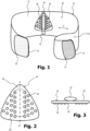
- a device according to the present invention is shown in perspective and generally designated 10.
- the device 10 includes a strap 12 made of an elastic material that is elastically stretchable along its longitudinal direction according to arrow E.
- the strap 12 has at one end 14 a flat Velcro fastener field 16 which is provided with Velcro hooks.
- the belt 12 has at its other end 18 a flat Velcro fastener field 20, which is designed as Velcro, the Velcro hooks of the field 16 being used to close the belt 12 around a patient's upper body Velcro of the field 20 can be variably brought into engagement sufficiently tightly to hold together even under elastic tension.
- the belt 12 has a pressure body 24 on its inside 22, which is designed in the shape of a triangle with rounded corners.
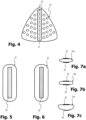
- the pressure body 24 is in front view Figure 2 , in top view Figure 3 and in rear view in Figure 4 shown.
- the pressure body 24 is made of a dimensionally stable but deformable rubber material and is covered at least on its front side 26 with a hygienic coating material that is easy to clean.
- the pressure body 24 has on its front side 26 a series of rounded knob-like projections 28, which are arranged in regular patterns, in particular on the side of an imaginary central axis A. No such projections 28 are provided in the area around the central axis A because that is where the largest proportion of the compressive force is exerted.
- a strip 32 made of a material with Velcro is firmly attached to the back 30 of the pressure body 24 in the area of its central axis A.
- a pressure cushion 34 is provided on the back 30 of the pressure body 24.
- Figure 5 shows a rear view of the pressure pad 34
- Figure 6 a front view of the pressure pad 34 shows.
- Figures 7a to 7c show different geometries that the pressure pad has in top view.
- the pressure pad 34 is designed as a dimensionally stable and relatively hard elongated silicone body with rounded corners and flattened edge areas.
- On its front ( Figure 6 ) it has an area 36 which is provided with Velcro and is approximately the same size as the area 32 of the pressure body.
- FIGs 7a to 7c show different geometries that the pressure pad can have.
- the pressure pad 34a has an elliptical shape in plan view, with the two Velcro fastener panels 36 and 38 being arranged on the front and back.
- the pressure pad 34b has a rounded rectangular shape or oval shape, again the two Velcro fastener panels 36 and 38 are arranged on the front and back.
- the pressure pad 34c has a strongly convexly curved shape on the front with the Velcro fastener field 36, whereas it has a flat shape on its back with the Velcro fastener field 38.
- the Velcro panel 38 is intended to fix the pressure pad on a corresponding Velcro panel with a Velcro on the inside 22 of the belt 12 or directly without the mediation of another Velcro panel directly on the inside 22 of the belt 12.
- the pressure pad can also have other geometries.
- it can be made shorter, more bulbous, more convex or less convex, flattened towards the patient or more curved towards the back, i.e. H. towards the belt, flattened or more curved, more bulbous in the front and back view, circular, elliptical or also triangular.
- FIG 8 shows a reinforcing element 40.
- This reinforcing element 40 is intended to be in a receiving pocket 42 on the belt 12 (see Figure 1 ) to be attached.
- the reinforcing element 40 is made of a dimensionally stable material, for example metal or a hard plastic material, such as a thermoplastic.
- the receiving pocket 42 is attached either to the inside 22 of the belt 12 or to the outside 44 of the belt 12. She is in Figure 1 only shown by dashed lines because they are in the embodiment according to Figure 1 on the outside 44 is attached.
- the reinforcing element 40 is curved with an angle of approximately 15°. The angle can be made larger or smaller depending on your needs.
- a vertex 46 is formed in the central region of the reinforcing element 40, which lies approximately in the central region of the belt 12.
- the orientation of the reinforcing element 40 is provided such that it is curved towards the patient in its end regions 48, 50, with the apex 46 pointing away from the patient. This arrangement allows the belt to be stabilized in the area of the pressure cushion 34 with the reinforcing element 40 in order to better exert pressure on the patient's stomach area via the pressure cushion 34 and finally the pressure body 24.
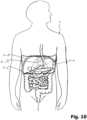
- Figure 10 To illustrate the use of the device according to the present invention, shows a patient P in a schematic representation, with his organs of the digestive tract being shown schematically in detail. In particular, you can see the representation of the stomach M, which is shown to be slightly larger in the patient.
- the belt 12 according to the present invention is applied to the patient, with a pressure force being exerted below the costal arch R via the pressure body 24 and the pressure cushion 36 in order to reduce the volume M available for the stomach. This makes it possible to effectively and permanently reduce the patient's feeling of hunger and effectively combat obesity.
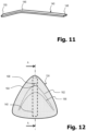
- Figure 11 shows an alternative embodiment for a reinforcing element 140, wherein the apex 146 lies in a region at the boundary between the first and second thirds of the total length of the reinforcing element.
- the opening angle is in the range of 150°.
- Figure 12 shows an alternative embodiment for a further pressure body 124.
- This is made, for example, from a dimensionally stable rubber material and has a triangular geometry, which is modeled on the contour of the human costal arch.
- the pressure body 124 is coated with a fleece material.
- the contour line 162 can be understood as a contour line and forms, so to speak, a ridge of a V-shaped elevation, which reaches the maximum elevation at its apex 164.
- a second contour line 166 shows the area a significantly reduced material thickness of the pressure body 124 below the contour line 162.
- a sensor 168 is provided, which is used to collect patient data, for example pulse and/or heart rate and/or blood pressure and/or blood sugar and/or respiratory rate and/or body temperature and/or fat content and/or water content or/ and muscle percentage and/or body mass index or the like.
- This sensor 168 can be coupled via a wireless interface to a user terminal, for example a smartphone, for data transmission.
- a user terminal for example a smartphone
- Figure 13a shows a section through the pressure body 124 along the section line AA. You can see the massive design made of a deformable foam or rubber material that is sufficiently dimensionally stable to exert pressure on the stomach area of a patient. You can also see the area 164 of maximum elevation and the sensor 168. In the illustration Figure 13a the pressure body 124 is shown without a reinforcing element.
- Figures 13b to 13e show various options for arranging the reinforcing element 140 on the pressure body 124.
- the reinforcing element 140 When arranged according to Figure 13b the reinforcing element 140 is arranged with its apex region 146 in such a way that the apex 146 presses convexly into the reinforcing element 140 in the region of the maximum elevation 164 and thus ensures maximum support of the pressure body 124 for applying pressure force to the patient's stomach area.
- the reinforcing element 140 When arranged according to Figure 13c the reinforcing element 140 is arranged with its apex region 146 in such a way that the apex 146 lies approximately at the height of the maximum elevation 164 of the pressure body 124, but is arranged concavely relative to it. As a result, the material of the pressure body 124 can, so to speak, escape into the concave apex area 146. As a result, the application of pressure force to the stomach area of a patient is significantly lower than with the arrangement according to Figure 13b .
- the different options for arranging the pressure body 124 and the reinforcing element 140 result in various possible variations for adjusting the pressure force exerted on the patient's stomach area. For example, as part of a therapy, by changing the arrangement of the reinforcing element 140, initially less and later more pressure can be exerted on the stomach area in order to control the course of therapy, for example with a gentle start to therapy using a low pressure force on the stomach area and then gradually increasing the pressure Compressive force application.
Landscapes
- Health & Medical Sciences (AREA)
- Life Sciences & Earth Sciences (AREA)
- Engineering & Computer Science (AREA)
- Public Health (AREA)
- Biomedical Technology (AREA)
- Heart & Thoracic Surgery (AREA)
- Animal Behavior & Ethology (AREA)
- General Health & Medical Sciences (AREA)
- Veterinary Medicine (AREA)
- Vascular Medicine (AREA)
- Orthopedic Medicine & Surgery (AREA)
- Nursing (AREA)
- Physics & Mathematics (AREA)
- Biophysics (AREA)
- Pathology (AREA)
- Medical Informatics (AREA)
- Molecular Biology (AREA)
- Surgery (AREA)
- Child & Adolescent Psychology (AREA)
- Obesity (AREA)
- Computer Networks & Wireless Communication (AREA)
- Orthopedics, Nursing, And Contraception (AREA)
- Surgical Instruments (AREA)
Claims (15)
- Dispositif (10) pour l'application externe d'une force de pression locale sous l'arc costal (R) d'un patient pour réduire le volume de l'estomac, comprenant :- une ceinture (12) qui peut être placée sous tension autour du torse d'un patient dans la zone de l'arc costal (R), et- un corps de pression (24) qui peut être fixé à la ceinture (12) et qui est conçu de telle sorte que, en utilisation, il exerce une force de pression sur l'estomac à l'intérieur du patient en fonction de la tension de la ceinture (12),caractérisé en ce quela ceinture (12) est réalisée sous la forme d'une ceinture élastique, et en ce quele corps de pression (24) est réalisé sous la forme d'une empreinte négative de l'arc costal et est ainsi adapté par sa géométrie à l'anatomie de l'arc costal humain et, en utilisation, s'y adapte.
- Dispositif (10) selon la revendication 1, dans lequel la ceinture élastique (12) est fermée ou réalisée sous la forme d'une bande au moins partiellement élastique qui, dans la zone de ses extrémités (14, 18), peut être reliée ensemble de manière réglable par des moyens de liaison (16, 20) pour régler sa longueur effective autour du torse du patient.
- Dispositif (10) selon la revendication 2, dans lequel les moyens de liaison (16, 20) sont réalisés sous la forme d'une fermeture auto-agrippante, dans lequel il est prévu de préférence une zone plate de velours auto-agrippant (20) à une extrémité et une zone plate de crochets auto-agrippants (16) à l'autre extrémité, ou dans lequel les moyens de liaison sont réalisés sous la forme d'au moins un élément de fermeture réglable, comme par exemple au moins une liaison ceinture-boucle ou un mécanisme d'encliquetage ou analogue.
- Dispositif (10) selon l'une des revendications précédentes, dans lequel le corps de pression (24) est réalisé sous la forme d'un corps de pression (24) plat et flexible, en particulier sous la forme d'un corps en caoutchouc, en matière plastique ou en silicone, qui est formé pour s'engager sous l'arc costal (R),dans lequel, de préférence, le corps de pression (24) est réalisé sous la forme d'un polygone arrondi, en particulier d'un triangle arrondi,dans lequel, en option, le corps de pression (24) est pourvu de picots (28) en saillie sur sa surface s'engageant sur le patient.
- Dispositif selon la revendication 4, dans lequel le corps de pression est réalisé avec une zone en relief en forme de V inversé, qui a sa plus grande épaisseur de matériau dans la zone du sommet du V.
- Dispositif (10) selon l'une des revendications 4 ou 5, dans lequel des moyens de fixation sont prévus sur la face arrière du corps de pression (24), en particulier une zone de velours auto-agrippant ou une zone de crochets auto-agrippants.
- Dispositif (10) selon l'une des revendications précédentes, dans lequel un coussin de pression (34) est prévu entre le corps de pression (24) et une face intérieure (22) de la ceinture (12) prévue pour s'appliquer contre le patient,
dans lequel le coussin de pression (34) est en particulier réalisé dans un matériau de forme stable, de préférence élastique, et est de préférence réalisé en caoutchouc, en matière plastique ou en silicone. - Dispositif (10) selon la revendication 7, dans lequel le coussin de pression (34) présente au moins d'un côté une forme convexe, dans lequel le coussin de pression (34) est en particulier réalisé avec une section transversale rectangulaire, rectangulaire arrondie, elliptique ou ovale.
- Dispositif (10) selon l'une des revendications 7 ou 8, dans lequel le coussin de pression (34) est réalisé avec des moyens de fixation (36, 38) sur sa face tournée vers la ceinture (12) ainsi que sur sa face tournée vers le corps de pression (24), en particulier avec une zone de velours auto-agrippant ou une zone de crochets auto-agrippants.
- Dispositif selon l'une des revendications 7 à 9, dans lequel le corps de pression est recouvert d'un matériau pelucheux, le matériau pelucheux étant directement formé sur le corps de pression ou étant réalisé sous la forme d'une poche en tissu interchangeable recevant le corps de pression.
- Dispositif (10) selon l'une des revendications précédentes, dans lequel la ceinture (12) est renforcée par un élément de renfort de forme stable (40) dans une zone dans laquelle le corps de pression (24) peut être appliqué, le cas échéant par l'intermédiaire du coussin de pression (34) selon l'une des revendications 6 à 10,
dans lequel, en particulier, la zone dans laquelle le corps de pression (24) peut être appliqué, le cas échéant par l'intermédiaire du coussin de pression (34) selon l'une des revendications 6 à 8, est disposée dans une partie centrale ou dans une zone d'extrémité de la ceinture (12). - Dispositif (10) selon la revendication 11, dans lequel la ceinture (12) comprend une poche de réception (42) destinée à recevoir l'élément de renfort (40).
- Dispositif (10) selon l'une des revendications 11 ou 12, dans lequel l'élément de renfort (40) est formé par une lame de renfort incurvée en arc de cercle qui est pourvue de deux zones d'extrémité (48, 50) en saillie par rapport à une zone centrale (46), dans lequel l'élément de renfort (50) est reçu dans la ceinture (12) ou fixé à celle-ci de telle sorte que les deux zones d'extrémité (48, 50), en utilisation, fassent saillie dans la direction d'application sur le patient.
- Dispositif (10) selon la revendication 13, dans lequel l'élément de renfort (140) comprend une zone de sommet (146) de forme arrondie qui est disposée de manière excentrée, de préférence dans une zone d'un tiers de la longueur totale de l'élément de renfort (140), dans lequel, de préférence, l'élément de renfort (140) présente dans sa zone de sommet (146) un angle d'ouverture de 170° à 120°, de manière la plus préférée un angle d'ouverture d'environ 150°,
dans lequel, en particulier, l'élément de renfort (140) peut être disposé au choix dans une disposition convexe ou concave par rapport au corps de pression (124) ou/et au choix avec sa zone de sommet (146) proche ou éloignée d'une épaisseur de matériau maximale du corps de pression (124). - Dispositif (10) selon l'une des revendications précédentes, dans lequel il est prévu dans la ceinture (12), dans une zone en contact avec la peau du patient, en particulier dans le corps de pression (24), au moins un capteur pour détecter des paramètres du patient, en particulier un capteur pour détecter le pouls, la fréquence cardiaque, la pression sanguine, la glycémie, la fréquence respiratoire, la température corporelle, le pourcentage de graisse, le pourcentage d'eau, le pourcentage de muscle, l'indice de masse corporelle ou analogue, dans lequel le capteur peut être couplé à un terminal pour la transmission de données par une liaison filaire ou sans fil, par exemple par IR, Bluetooth, WI-FI ou une liaison de téléphonie mobile.
Applications Claiming Priority (2)
| Application Number | Priority Date | Filing Date | Title |
|---|---|---|---|
| DE102016015072.6A DE102016015072A1 (de) | 2016-12-08 | 2016-12-08 | Vorrichtung zum externen Aufbringen einer lokalen Druckkraft unterhalb des Rippenbogens eines Patienten zur Verkleinerung des Magenvolumens |
| PCT/EP2017/081827 WO2018104450A1 (fr) | 2016-12-08 | 2017-12-07 | Dispositif destiné à l'application externe d'une force de pression locale en dessous de l'arc costal d'un patient destinée à la réduction du volume de l'estomac |
Publications (2)
| Publication Number | Publication Date |
|---|---|
| EP3551141A1 EP3551141A1 (fr) | 2019-10-16 |
| EP3551141B1 true EP3551141B1 (fr) | 2024-01-24 |
Family
ID=60857029
Family Applications (1)
| Application Number | Title | Priority Date | Filing Date |
|---|---|---|---|
| EP17822184.2A Active EP3551141B1 (fr) | 2016-12-08 | 2017-12-07 | Dispositif destiné à l'application externe d'une force de pression locale en dessous de l'arc costal d'un patient destinée à la réduction du volume de l'estomac |
Country Status (6)
| Country | Link |
|---|---|
| US (1) | US11617669B2 (fr) |
| EP (1) | EP3551141B1 (fr) |
| CN (1) | CN110139630A (fr) |
| DE (1) | DE102016015072A1 (fr) |
| MA (1) | MA48601A (fr) |
| WO (1) | WO2018104450A1 (fr) |
Families Citing this family (1)
| Publication number | Priority date | Publication date | Assignee | Title |
|---|---|---|---|---|
| US11974936B1 (en) * | 2024-01-18 | 2024-05-07 | Sean Meyer | Lumbosacral support device, method and kit |
Citations (4)
| Publication number | Priority date | Publication date | Assignee | Title |
|---|---|---|---|---|
| US2671899A (en) * | 1952-05-22 | 1954-03-16 | William S Kroger | Article to alleviate hunger of the stomach |
| US3578773A (en) * | 1968-10-28 | 1971-05-18 | August L Schultz | Supportive orthopedic device |
| DE3500078A1 (de) * | 1984-01-03 | 1985-07-11 | Samuel Saeed La Jolla Calif. Salmasian | Verfahren und vorrichtung zum verringern des koerpergewichts |
| DE19822221A1 (de) * | 1998-05-18 | 1999-11-25 | Andreas Grieger | Hilfsmittel zur Kontrolle des Hungergefühls |
Family Cites Families (10)
| Publication number | Priority date | Publication date | Assignee | Title |
|---|---|---|---|---|
| US1501672A (en) * | 1922-11-29 | 1924-07-15 | Lawton Thomas | Obesity-reducing band |
| US1535822A (en) * | 1923-07-05 | 1925-04-28 | Goodwin Roy | Remedial appliance |
| US4411258A (en) * | 1980-03-10 | 1983-10-25 | Pujals Jr Charles | Method and device for relieving pain |
| US5062414A (en) * | 1989-02-08 | 1991-11-05 | Royce Medical Company | Simplified orthopaedic back support |
| US4991573A (en) * | 1990-03-26 | 1991-02-12 | Miller Donald L | Orthopedic support belt |
| DE10207887A1 (de) * | 2002-02-23 | 2003-09-04 | Paul Icking | Appetitregulierender Magendrücker |
| US7264600B2 (en) * | 2004-07-02 | 2007-09-04 | Brinston Sr Charles Lee | Belt for body weight control |
| WO2010042080A1 (fr) * | 2008-10-11 | 2010-04-15 | Meshut Basak | Corset utilisé à des fins d'amincissement |
| CN103536278A (zh) * | 2013-09-18 | 2014-01-29 | 北京航空航天大学 | 新型健康监护系统 |
| CN106073739A (zh) * | 2016-08-15 | 2016-11-09 | 武汉清易云康医疗设备有限公司 | 集成可穿戴式多生理指标采集设备 |
-
2016
- 2016-12-08 DE DE102016015072.6A patent/DE102016015072A1/de not_active Withdrawn
-
2017
- 2017-12-07 EP EP17822184.2A patent/EP3551141B1/fr active Active
- 2017-12-07 CN CN201780075998.3A patent/CN110139630A/zh active Pending
- 2017-12-07 WO PCT/EP2017/081827 patent/WO2018104450A1/fr unknown
- 2017-12-07 MA MA048601A patent/MA48601A/fr unknown
- 2017-12-07 US US16/467,904 patent/US11617669B2/en active Active
Patent Citations (4)
| Publication number | Priority date | Publication date | Assignee | Title |
|---|---|---|---|---|
| US2671899A (en) * | 1952-05-22 | 1954-03-16 | William S Kroger | Article to alleviate hunger of the stomach |
| US3578773A (en) * | 1968-10-28 | 1971-05-18 | August L Schultz | Supportive orthopedic device |
| DE3500078A1 (de) * | 1984-01-03 | 1985-07-11 | Samuel Saeed La Jolla Calif. Salmasian | Verfahren und vorrichtung zum verringern des koerpergewichts |
| DE19822221A1 (de) * | 1998-05-18 | 1999-11-25 | Andreas Grieger | Hilfsmittel zur Kontrolle des Hungergefühls |
Also Published As
| Publication number | Publication date |
|---|---|
| WO2018104450A1 (fr) | 2018-06-14 |
| DE102016015072A1 (de) | 2018-06-14 |
| CN110139630A (zh) | 2019-08-16 |
| US11617669B2 (en) | 2023-04-04 |
| US20200060857A1 (en) | 2020-02-27 |
| EP3551141A1 (fr) | 2019-10-16 |
| MA48601A (fr) | 2020-03-18 |
Similar Documents
| Publication | Publication Date | Title |
|---|---|---|
| DE102011018470B4 (de) | Bandage und Elektrodensystem | |
| DE212010000006U1 (de) | Orthopädische Vorrichtung | |
| DE10329454A1 (de) | Orthopädische Stützeinrichtung für Rücken- und Lumbalbereich | |
| WO2016185029A1 (fr) | Dispositif pour normaliser la posture des épaules d'un être humain | |
| AT500022A1 (de) | Trainings- und therapievorrichtung für hunde | |
| DE202014009969U1 (de) | Orthopädische Bandagen mit Wärmeapplikator, Wärmeapplikator, sowie Pelotte | |
| EP1319379B1 (fr) | Orthèse pour le traitement des lésions de l'articulation acromio-claviculaire de l'épaule | |
| EP3551141B1 (fr) | Dispositif destiné à l'application externe d'une force de pression locale en dessous de l'arc costal d'un patient destinée à la réduction du volume de l'estomac | |
| EP2874579B1 (fr) | Orthèse d'abduction d'épaule | |
| EP3634323B1 (fr) | Dispositif pour l'utilisation comme moyen therapeutique pour le traitement de la camptocormie | |
| WO2009129780A1 (fr) | Auxiliaire orthopédique muni d'un élément fonctionnel insérable | |
| DE202007002380U1 (de) | Therapiehandschuh | |
| WO2019091894A1 (fr) | Coussin destiné à être utilisé après une opération du sein | |
| EP3057543B1 (fr) | Orthèse de pouce | |
| DE202011100771U1 (de) | Stomabandage | |
| WO2005120404A1 (fr) | Bandage pour l'epaule et le bras | |
| AT502986B1 (de) | Stützbandage | |
| DE19606294C1 (de) | Anti-Schnarchbandage | |
| DE3316435C2 (de) | Bruchband mit auswechselbarer Bruchschale | |
| DE202021001919U1 (de) | Funktionsshirt mit Faszienaktivierungszonen und rumpfstabilisierenden Klett- und Tapebändern | |
| EP2929863B1 (fr) | Bande compressive | |
| DE202021003430U1 (de) | Funktionsshirt mit Faszienaktivierungszonen und rumpfstabilisierenden Klett- und Tapebändern | |
| DE202011107938U1 (de) | Gerät zur Anregung der Nackenmuskeln und Nerven im Nacken | |
| DE102008016885B4 (de) | Zungen-Lippen-Gesichtstrainer | |
| EP4101423A1 (fr) | Dispositif de traitement d'un organisme contre les troubles pondéraux |
Legal Events
| Date | Code | Title | Description |
|---|---|---|---|
| STAA | Information on the status of an ep patent application or granted ep patent |
Free format text: STATUS: UNKNOWN |
|
| STAA | Information on the status of an ep patent application or granted ep patent |
Free format text: STATUS: THE INTERNATIONAL PUBLICATION HAS BEEN MADE |
|
| PUAI | Public reference made under article 153(3) epc to a published international application that has entered the european phase |
Free format text: ORIGINAL CODE: 0009012 |
|
| STAA | Information on the status of an ep patent application or granted ep patent |
Free format text: STATUS: REQUEST FOR EXAMINATION WAS MADE |
|
| 17P | Request for examination filed |
Effective date: 20190522 |
|
| AK | Designated contracting states |
Kind code of ref document: A1 Designated state(s): AL AT BE BG CH CY CZ DE DK EE ES FI FR GB GR HR HU IE IS IT LI LT LU LV MC MK MT NL NO PL PT RO RS SE SI SK SM TR |
|
| AX | Request for extension of the european patent |
Extension state: BA ME |
|
| DAX | Request for extension of the european patent (deleted) | ||
| RAV | Requested validation state of the european patent: fee paid |
Extension state: MA Effective date: 20190522 |
|
| STAA | Information on the status of an ep patent application or granted ep patent |
Free format text: STATUS: EXAMINATION IS IN PROGRESS |
|
| STAA | Information on the status of an ep patent application or granted ep patent |
Free format text: STATUS: EXAMINATION IS IN PROGRESS |
|
| 17Q | First examination report despatched |
Effective date: 20210714 |
|
| GRAP | Despatch of communication of intention to grant a patent |
Free format text: ORIGINAL CODE: EPIDOSNIGR1 |
|
| STAA | Information on the status of an ep patent application or granted ep patent |
Free format text: STATUS: GRANT OF PATENT IS INTENDED |
|
| INTG | Intention to grant announced |
Effective date: 20230727 |
|
| GRAS | Grant fee paid |
Free format text: ORIGINAL CODE: EPIDOSNIGR3 |
|
| GRAA | (expected) grant |
Free format text: ORIGINAL CODE: 0009210 |
|
| STAA | Information on the status of an ep patent application or granted ep patent |
Free format text: STATUS: THE PATENT HAS BEEN GRANTED |
|
| RAP3 | Party data changed (applicant data changed or rights of an application transferred) |
Owner name: CEBE, FEVZI |
|
| RIN1 | Information on inventor provided before grant (corrected) |
Inventor name: CEBE, FEVZI |
|
| AK | Designated contracting states |
Kind code of ref document: B1 Designated state(s): AL AT BE BG CH CY CZ DE DK EE ES FI FR GB GR HR HU IE IS IT LI LT LU LV MC MK MT NL NO PL PT RO RS SE SI SK SM TR |
|
| REG | Reference to a national code |
Ref country code: GB Ref legal event code: FG4D Free format text: NOT ENGLISH |
|
| REG | Reference to a national code |
Ref country code: CH Ref legal event code: EP |
|
| REG | Reference to a national code |
Ref country code: IE Ref legal event code: FG4D Free format text: LANGUAGE OF EP DOCUMENT: GERMAN |
|
| REG | Reference to a national code |
Ref country code: DE Ref legal event code: R096 Ref document number: 502017015793 Country of ref document: DE |
|
| U01 | Request for unitary effect filed |
Effective date: 20240219 |
|
| U07 | Unitary effect registered |
Designated state(s): AT BE BG DE DK EE FI FR IT LT LU LV MT NL PT SE SI Effective date: 20240228 |
|
| REG | Reference to a national code |
Ref country code: LT Ref legal event code: MG9D |
|
| PG25 | Lapsed in a contracting state [announced via postgrant information from national office to epo] |
Ref country code: IS Free format text: LAPSE BECAUSE OF FAILURE TO SUBMIT A TRANSLATION OF THE DESCRIPTION OR TO PAY THE FEE WITHIN THE PRESCRIBED TIME-LIMIT Effective date: 20240524 |
|
| PG25 | Lapsed in a contracting state [announced via postgrant information from national office to epo] |
Ref country code: GR Free format text: LAPSE BECAUSE OF FAILURE TO SUBMIT A TRANSLATION OF THE DESCRIPTION OR TO PAY THE FEE WITHIN THE PRESCRIBED TIME-LIMIT Effective date: 20240425 |
|
| PG25 | Lapsed in a contracting state [announced via postgrant information from national office to epo] |
Ref country code: HR Free format text: LAPSE BECAUSE OF FAILURE TO SUBMIT A TRANSLATION OF THE DESCRIPTION OR TO PAY THE FEE WITHIN THE PRESCRIBED TIME-LIMIT Effective date: 20240124 Ref country code: RS Free format text: LAPSE BECAUSE OF FAILURE TO SUBMIT A TRANSLATION OF THE DESCRIPTION OR TO PAY THE FEE WITHIN THE PRESCRIBED TIME-LIMIT Effective date: 20240424 |
|
| PG25 | Lapsed in a contracting state [announced via postgrant information from national office to epo] |
Ref country code: ES Free format text: LAPSE BECAUSE OF FAILURE TO SUBMIT A TRANSLATION OF THE DESCRIPTION OR TO PAY THE FEE WITHIN THE PRESCRIBED TIME-LIMIT Effective date: 20240124 |
|
| PG25 | Lapsed in a contracting state [announced via postgrant information from national office to epo] |
Ref country code: RS Free format text: LAPSE BECAUSE OF FAILURE TO SUBMIT A TRANSLATION OF THE DESCRIPTION OR TO PAY THE FEE WITHIN THE PRESCRIBED TIME-LIMIT Effective date: 20240424 Ref country code: NO Free format text: LAPSE BECAUSE OF FAILURE TO SUBMIT A TRANSLATION OF THE DESCRIPTION OR TO PAY THE FEE WITHIN THE PRESCRIBED TIME-LIMIT Effective date: 20240424 Ref country code: IS Free format text: LAPSE BECAUSE OF FAILURE TO SUBMIT A TRANSLATION OF THE DESCRIPTION OR TO PAY THE FEE WITHIN THE PRESCRIBED TIME-LIMIT Effective date: 20240524 Ref country code: HR Free format text: LAPSE BECAUSE OF FAILURE TO SUBMIT A TRANSLATION OF THE DESCRIPTION OR TO PAY THE FEE WITHIN THE PRESCRIBED TIME-LIMIT Effective date: 20240124 Ref country code: GR Free format text: LAPSE BECAUSE OF FAILURE TO SUBMIT A TRANSLATION OF THE DESCRIPTION OR TO PAY THE FEE WITHIN THE PRESCRIBED TIME-LIMIT Effective date: 20240425 Ref country code: ES Free format text: LAPSE BECAUSE OF FAILURE TO SUBMIT A TRANSLATION OF THE DESCRIPTION OR TO PAY THE FEE WITHIN THE PRESCRIBED TIME-LIMIT Effective date: 20240124 |
|
| PG25 | Lapsed in a contracting state [announced via postgrant information from national office to epo] |
Ref country code: PL Free format text: LAPSE BECAUSE OF FAILURE TO SUBMIT A TRANSLATION OF THE DESCRIPTION OR TO PAY THE FEE WITHIN THE PRESCRIBED TIME-LIMIT Effective date: 20240124 |
|
| PG25 | Lapsed in a contracting state [announced via postgrant information from national office to epo] |
Ref country code: PL Free format text: LAPSE BECAUSE OF FAILURE TO SUBMIT A TRANSLATION OF THE DESCRIPTION OR TO PAY THE FEE WITHIN THE PRESCRIBED TIME-LIMIT Effective date: 20240124 |
|
| PG25 | Lapsed in a contracting state [announced via postgrant information from national office to epo] |
Ref country code: SM Free format text: LAPSE BECAUSE OF FAILURE TO SUBMIT A TRANSLATION OF THE DESCRIPTION OR TO PAY THE FEE WITHIN THE PRESCRIBED TIME-LIMIT Effective date: 20240124 |