EP3551141B1 - Device for the external application of a local compressive force below the costal arch of a patient to reduce the stomach volume - Google Patents
Device for the external application of a local compressive force below the costal arch of a patient to reduce the stomach volume Download PDFInfo
- Publication number
- EP3551141B1 EP3551141B1 EP17822184.2A EP17822184A EP3551141B1 EP 3551141 B1 EP3551141 B1 EP 3551141B1 EP 17822184 A EP17822184 A EP 17822184A EP 3551141 B1 EP3551141 B1 EP 3551141B1
- Authority
- EP
- European Patent Office
- Prior art keywords
- pressure
- patient
- belt
- pressure body
- area
- Prior art date
- Legal status (The legal status is an assumption and is not a legal conclusion. Google has not performed a legal analysis and makes no representation as to the accuracy of the status listed.)
- Active
Links
Images


Classifications
-
- A—HUMAN NECESSITIES
- A61—MEDICAL OR VETERINARY SCIENCE; HYGIENE
- A61F—FILTERS IMPLANTABLE INTO BLOOD VESSELS; PROSTHESES; DEVICES PROVIDING PATENCY TO, OR PREVENTING COLLAPSING OF, TUBULAR STRUCTURES OF THE BODY, e.g. STENTS; ORTHOPAEDIC, NURSING OR CONTRACEPTIVE DEVICES; FOMENTATION; TREATMENT OR PROTECTION OF EYES OR EARS; BANDAGES, DRESSINGS OR ABSORBENT PADS; FIRST-AID KITS
- A61F5/00—Orthopaedic methods or devices for non-surgical treatment of bones or joints; Nursing devices ; Anti-rape devices
- A61F5/0003—Apparatus for the treatment of obesity; Anti-eating devices
- A61F5/0009—External belts
-
- A—HUMAN NECESSITIES
- A61—MEDICAL OR VETERINARY SCIENCE; HYGIENE
- A61B—DIAGNOSIS; SURGERY; IDENTIFICATION
- A61B5/00—Measuring for diagnostic purposes; Identification of persons
- A61B5/0002—Remote monitoring of patients using telemetry, e.g. transmission of vital signals via a communication network
- A61B5/0015—Remote monitoring of patients using telemetry, e.g. transmission of vital signals via a communication network characterised by features of the telemetry system
- A61B5/0017—Remote monitoring of patients using telemetry, e.g. transmission of vital signals via a communication network characterised by features of the telemetry system transmitting optical signals
-
- A—HUMAN NECESSITIES
- A61—MEDICAL OR VETERINARY SCIENCE; HYGIENE
- A61B—DIAGNOSIS; SURGERY; IDENTIFICATION
- A61B5/00—Measuring for diagnostic purposes; Identification of persons
- A61B5/48—Other medical applications
- A61B5/4836—Diagnosis combined with treatment in closed-loop systems or methods
-
- A—HUMAN NECESSITIES
- A61—MEDICAL OR VETERINARY SCIENCE; HYGIENE
- A61F—FILTERS IMPLANTABLE INTO BLOOD VESSELS; PROSTHESES; DEVICES PROVIDING PATENCY TO, OR PREVENTING COLLAPSING OF, TUBULAR STRUCTURES OF THE BODY, e.g. STENTS; ORTHOPAEDIC, NURSING OR CONTRACEPTIVE DEVICES; FOMENTATION; TREATMENT OR PROTECTION OF EYES OR EARS; BANDAGES, DRESSINGS OR ABSORBENT PADS; FIRST-AID KITS
- A61F5/00—Orthopaedic methods or devices for non-surgical treatment of bones or joints; Nursing devices ; Anti-rape devices
- A61F5/01—Orthopaedic devices, e.g. long-term immobilising or pressure directing devices for treating broken or deformed bones such as splints, casts or braces
- A61F5/03—Corsets or bandages for abdomen, teat or breast support, with or without pads
Definitions
- the present invention relates to a device for externally applying a local pressure force below the costal arch of a patient to reduce the volume of the stomach.
- the treatment of overweight people who suffer from metabolic diseases or obesity is becoming increasingly important.
- One approach to this treatment is to reduce a patient's stomach volume.
- there are particularly invasive or surgical forms of treatment such as applying a gastric band, surgically performing a stomach reduction or inserting a gastric balloon.
- Surgical forms of treatment usually lead to a certain degree of success in the short term and at least temporarily, but they cannot be carried out as often as desired in patients who repeatedly tend to be overweight, usually only a few times. For example, a patient can usually only undergo a stomach reduction once.
- surgical forms of treatment bring with them the well-known side effects of a surgical procedure, so that these forms of treatment are not an option for all patients.
- surgical procedures are costly and pose a risk to the patient.
- Drug treatment approaches usually have significant side effects that put unnecessary strain on the patient's organism.
- US 7,264,600 B2 describes an active belt for weight control. This can be used to specifically inflate air cushions. It also describes a type of massage function.
- DE 102 07 887 A1 discloses a device in which a pressure application can be generated pneumatically or hydraulically in the stomach area from the outside.
- US 2,671,899 is considered the closest prior art and discloses a device for achieving an increase in pressure in the epigastric region of a patient, wherein a hollow body attached to a belt is provided, which is formed with individual ventilation openings and is intended to exert pressure on the epigastric region.
- WO 2010/042080 A1 describes a corset that, on the one hand, is intended to improve the external appearance of a patient through shaping and, on the other hand, to curb a patient's appetite by specifically applying pressure to the stomach area.
- DE 198 22 221 A1 discloses another device for applying pressure to the stomach region of a patient with various padding elements.
- US 3,578,773 A discloses an orthopedic belt with a pressure body, wherein targeted pressure is applied to specific muscles, injuries or weakened areas of a patient's upper body.
- the present invention is based on the object of providing a device which is suitable for reducing the size of a patient's stomach.
- the inventor has recognized that it is fundamentally possible to permanently reduce the stomach volume of a patient by applying a pressure force to the patient's body in the area of the stomach area from the outside and thus reduce the patient's feeling of hunger.
- the elastic belt which is under tension, is placed around the patient's upper body in the area of the costal arch.
- the compressive force exerted in the radial direction by the elastic tension of the belt on the patient's upper body is at least partially concentrated at points or locally via the pressure body on the area of the stomach area and a pressure force is thus permanently exerted on the patient's stomach area.
- the pressure body with its geometry tailored to the patient's costal arch, nestles into it and thus applies the pressure force there.
- the pressure body is designed in the form of a negative impression of the rib arch.
- the pressure body causes compression of the upper abdomen in the area of the epigastrium (stomach), whereby the air in the stomach is compressed or squeezed out and the stomach volume is permanently reduced and restricted.
- the organs in the abdominal cavity lie in an airless space (vacuum) and the stomach and intestines are the only organs that can contain air. Pressure applied to the abdominal cavity is therefore transmitted directly to the stomach and intestines and leads to volume reduction at the desired location.
- the device according to the invention can be used to achieve a permanent and constant volume reduction by means of moderate but continuous compression on the stomach, which has a reducing effect on the patient's feeling of hunger and eating behavior.
- a reduction in the stomach volume can be achieved conservatively, ie without surgical or medical intervention, so that the patient feels less hunger and will therefore reduce his excess weight over time due to lower food intake.
- the elastic belt is closed or is designed in the form of an at least partially elastic band, which can be adjustably connected to one another in the area of its ends via connecting means for adjusting its effective length around the patient's upper body.
- the belt is closed, it is preferably offered in different sizes so that it can be used by patients with different body sizes.
- an open, band-shaped belt is preferably used, which can be closed at its ends with connecting means.
- the connecting means are designed in the form of a Velcro fastener, with a flat Velcro area preferably being provided at one end and a flat Velcro hook area being provided at the other end, or the connecting means being in the form of at least one adjustable closure element, such as at least a belt-buckle connection or a rotary locking mechanism or locking mechanism or the like.
- the belt can be adapted to any patient, with different belt lengths preferably being offered as basic sizes.
- the pressure body is designed in the form of a flat, flexible pressure body.
- the pressure body can in particular be designed in the form of a rubber, plastic or silicone body.
- the pressure body is designed in such a way that it is suitable for attacking below the costal arch, i.e. H. in such a way that the pressure body, with which the pressure force is exerted via the patient's skin on the stomach area, can engage in the stomach area below the costal arch. This allows the desired pressure force to be specifically exerted on the stomach area and thus permanently and conservatively reduces the stomach volume.
- the pressure body is designed in the form of a rounded polygon, in particular a rounded triangle, an ellipse or an oval.
- a suitable geometry for the pressure body can be selected depending on the patient.
- the pressure body is designed with an inverted V-shaped elevation area, which has its greatest material thickness in the area of the V apex.
- the V-shaped elevation area with its largest elevation in the area of the V apex fits anatomically into the costal arch and ensures maximum pressure application at its area of greatest elevation (epigastrium), ideally on or in the area of the patient's solar plexus.
- the elevation area along the V-legs increases the pressure concentration in the upper abdomen.
- the pressure body is provided with projecting knobs on its surface that engages the patient. This measure ensures that the pressure body remains better in its target position on the patient. In addition, even when the device according to the invention is worn permanently, a certain amount of air circulation will be possible in the area of the pressure body, which increases wearing comfort.
- fastening means are provided on the back of the pressure body, in particular a Velcro area or a Velcro hook area. This allows the pressure body to be fixed to the belt or, as described in more detail below, to a pressure cushion additionally arranged between the belt and the pressure body.
- fastening means such as buttons, snap fasteners, locking elements, form-fitting elements, magnets or the like can also be provided.
- a further development of the invention provides that a pressure cushion is provided between the pressure body and an inside of the belt intended to rest against the patient.
- a pressure cushion also known as a "pad” in technical jargon, enables the pressure force to be applied selectively or over a wide area to suit the anatomy of the patient if the geometry of this pressure cushion is selected appropriately.
- the pressure body cannot be made as rigid as desired. Rather, when designing the pressure body, which comes into direct contact with the patient's skin, attention must be paid to skin compatibility and the avoidance of unpleasant pressure points or rubbing areas that can lead to skin irritation.
- the pressure body has a skin-friendly coating or a cover, in particular made of a cleanable or hygienic textile material.
- the pressure pad can be made from a harder material, for example from a dimensionally stable, preferably elastic material, preferably from rubber, plastic or silicone.
- the pressure pad can also be provided with a coating or a cleanable cover.
- the geometry of the pressure cushion can be geometrically coordinated, particularly with regard to the desired target range in which the pressure force should be exerted on the patient to reduce the stomach volume.
- the pressure body is covered with a fleece material, wherein the fleece material is formed directly on the pressure body or is designed in the form of a replaceable fabric bag that accommodates the pressure body.
- the pressure cushion With regard to the geometry of the pressure cushion, it can be provided that it is convex, i.e. H. curved outwards, the pressure pad can be designed to be rectangular, rounded rectangular, elliptical or oval, in particular in cross section. As indicated above, pressure cushions of different geometry and hardness can be used depending on the anatomical conditions of the patient and the treatment situation.
- the pressure cushion is designed with fastening means, in particular with a Velcro area or a Velcro hook area, on its side facing the belt and on its side facing the pressure body.
- fastening means in particular with a Velcro area or a Velcro hook area
- buttons, snap fasteners, locking elements, form-fitting elements, magnets or the like can be used to fix the pressure pad.
- a further development of the invention provides that the belt is reinforced by a dimensionally stable reinforcing element in an area in which the pressure body can be attached, if necessary with the aid of the pressure cushion described above.
- a reinforcing element for example, the pressure cushion and/or the pressure body can be stabilized in its position relative to the patient, whereby the permanent application of a pressure force is guaranteed even more reliably.
- the area in which the pressure body can be attached, if necessary via the pressure cushion and is arranged in a central section or in an end region of the belt. Depending on the design, this can result in the belt being able to be closed, for example, in a back area of the patient or in the patient's chest area.
- the reinforcing element can have a rounded apex region which is arranged off-center, preferably in an area of a third of the total length of the reinforcing element, wherein preferably the reinforcing element has an opening angle of 170 ° to 120 ° in its apex region, most of all preferably has an opening angle of approximately 150°. This makes it possible to bring the apex area into alignment with the area of maximum material thickness or maximum elevation of the body in coordination with the pressure body for maximum application of pressure force.
- This design of the reinforcing element also allows variable use of the reinforcing element in different arrangements relative to the pressure body in order to apply less or more pressure to the stomach area depending on the patient's needs. It can be provided that the reinforcing element can be arranged either in a convex or concave arrangement relative to the pressure body and/or optionally with its apex region close to or away from a maximum material thickness of the pressure body. In other words, depending on the orientation of the reinforcing element, it is possible to support the pressure force applied to the stomach area by the pressure body to a greater or lesser extent via the reinforcing element.
- a further development of the invention preferably provides that the belt has a recess or receiving pocket for receiving the reinforcing element. This ensures that the reinforcing element remains stable in position in the belt.
- the reinforcing element is formed by an arcuately curved reinforcing strip, which is provided with two end regions projecting relative to a central region, the reinforcing element being accommodated in the belt or attached to it in such a way that the two end regions are directed towards protrude towards the patient.
- the reinforcement bar can be, for example, a metal strip or a stable plastic strip made of a thermoplastic material or the like.
- a further development of the invention provides that at least one sensor for detecting patient parameters is provided in the belt in an area in contact with the patient's skin, in particular in the pressure body, in particular a sensor for detecting pulse and/or heart rate or /and blood pressure or/and blood sugar or/and breathing rate or/and body temperature or/and fat percentage or/and water percentage or/and muscle percentage or/and body mass index or the like.
- sensors can include electrodes that come into direct contact with the patient's skin.
- These sensors can, for example, be powered by a common supply unit in the form of a battery.
- the sensors can be coupled via a wired interface or wirelessly, for example via IR, Bluetooth, WI-FI or a mobile phone connection, to an evaluation unit, for example a smartphone or a smartwatch or a computer or a tablet or an electronic scale or another electronic evaluation unit.
- an evaluation unit for example a smartphone or a smartwatch or a computer or a tablet or an electronic scale or another electronic evaluation unit.
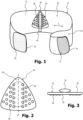
- a device according to the present invention is shown in perspective and generally designated 10.
- the device 10 includes a strap 12 made of an elastic material that is elastically stretchable along its longitudinal direction according to arrow E.
- the strap 12 has at one end 14 a flat Velcro fastener field 16 which is provided with Velcro hooks.
- the belt 12 has at its other end 18 a flat Velcro fastener field 20, which is designed as Velcro, the Velcro hooks of the field 16 being used to close the belt 12 around a patient's upper body Velcro of the field 20 can be variably brought into engagement sufficiently tightly to hold together even under elastic tension.
- the belt 12 has a pressure body 24 on its inside 22, which is designed in the shape of a triangle with rounded corners.
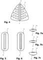
- the pressure body 24 is in front view Figure 2 , in top view Figure 3 and in rear view in Figure 4 shown.
- the pressure body 24 is made of a dimensionally stable but deformable rubber material and is covered at least on its front side 26 with a hygienic coating material that is easy to clean.
- the pressure body 24 has on its front side 26 a series of rounded knob-like projections 28, which are arranged in regular patterns, in particular on the side of an imaginary central axis A. No such projections 28 are provided in the area around the central axis A because that is where the largest proportion of the compressive force is exerted.
- a strip 32 made of a material with Velcro is firmly attached to the back 30 of the pressure body 24 in the area of its central axis A.
- a pressure cushion 34 is provided on the back 30 of the pressure body 24.
- Figure 5 shows a rear view of the pressure pad 34
- Figure 6 a front view of the pressure pad 34 shows.
- Figures 7a to 7c show different geometries that the pressure pad has in top view.
- the pressure pad 34 is designed as a dimensionally stable and relatively hard elongated silicone body with rounded corners and flattened edge areas.
- On its front ( Figure 6 ) it has an area 36 which is provided with Velcro and is approximately the same size as the area 32 of the pressure body.
- FIGs 7a to 7c show different geometries that the pressure pad can have.
- the pressure pad 34a has an elliptical shape in plan view, with the two Velcro fastener panels 36 and 38 being arranged on the front and back.
- the pressure pad 34b has a rounded rectangular shape or oval shape, again the two Velcro fastener panels 36 and 38 are arranged on the front and back.
- the pressure pad 34c has a strongly convexly curved shape on the front with the Velcro fastener field 36, whereas it has a flat shape on its back with the Velcro fastener field 38.
- the Velcro panel 38 is intended to fix the pressure pad on a corresponding Velcro panel with a Velcro on the inside 22 of the belt 12 or directly without the mediation of another Velcro panel directly on the inside 22 of the belt 12.
- the pressure pad can also have other geometries.
- it can be made shorter, more bulbous, more convex or less convex, flattened towards the patient or more curved towards the back, i.e. H. towards the belt, flattened or more curved, more bulbous in the front and back view, circular, elliptical or also triangular.
- FIG 8 shows a reinforcing element 40.
- This reinforcing element 40 is intended to be in a receiving pocket 42 on the belt 12 (see Figure 1 ) to be attached.
- the reinforcing element 40 is made of a dimensionally stable material, for example metal or a hard plastic material, such as a thermoplastic.
- the receiving pocket 42 is attached either to the inside 22 of the belt 12 or to the outside 44 of the belt 12. She is in Figure 1 only shown by dashed lines because they are in the embodiment according to Figure 1 on the outside 44 is attached.
- the reinforcing element 40 is curved with an angle of approximately 15°. The angle can be made larger or smaller depending on your needs.
- a vertex 46 is formed in the central region of the reinforcing element 40, which lies approximately in the central region of the belt 12.
- the orientation of the reinforcing element 40 is provided such that it is curved towards the patient in its end regions 48, 50, with the apex 46 pointing away from the patient. This arrangement allows the belt to be stabilized in the area of the pressure cushion 34 with the reinforcing element 40 in order to better exert pressure on the patient's stomach area via the pressure cushion 34 and finally the pressure body 24.
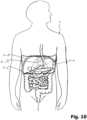
- Figure 10 To illustrate the use of the device according to the present invention, shows a patient P in a schematic representation, with his organs of the digestive tract being shown schematically in detail. In particular, you can see the representation of the stomach M, which is shown to be slightly larger in the patient.
- the belt 12 according to the present invention is applied to the patient, with a pressure force being exerted below the costal arch R via the pressure body 24 and the pressure cushion 36 in order to reduce the volume M available for the stomach. This makes it possible to effectively and permanently reduce the patient's feeling of hunger and effectively combat obesity.
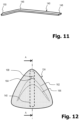
- Figure 11 shows an alternative embodiment for a reinforcing element 140, wherein the apex 146 lies in a region at the boundary between the first and second thirds of the total length of the reinforcing element.
- the opening angle is in the range of 150°.
- Figure 12 shows an alternative embodiment for a further pressure body 124.
- This is made, for example, from a dimensionally stable rubber material and has a triangular geometry, which is modeled on the contour of the human costal arch.
- the pressure body 124 is coated with a fleece material.
- the contour line 162 can be understood as a contour line and forms, so to speak, a ridge of a V-shaped elevation, which reaches the maximum elevation at its apex 164.
- a second contour line 166 shows the area a significantly reduced material thickness of the pressure body 124 below the contour line 162.
- a sensor 168 is provided, which is used to collect patient data, for example pulse and/or heart rate and/or blood pressure and/or blood sugar and/or respiratory rate and/or body temperature and/or fat content and/or water content or/ and muscle percentage and/or body mass index or the like.
- This sensor 168 can be coupled via a wireless interface to a user terminal, for example a smartphone, for data transmission.
- a user terminal for example a smartphone
- Figure 13a shows a section through the pressure body 124 along the section line AA. You can see the massive design made of a deformable foam or rubber material that is sufficiently dimensionally stable to exert pressure on the stomach area of a patient. You can also see the area 164 of maximum elevation and the sensor 168. In the illustration Figure 13a the pressure body 124 is shown without a reinforcing element.
- Figures 13b to 13e show various options for arranging the reinforcing element 140 on the pressure body 124.
- the reinforcing element 140 When arranged according to Figure 13b the reinforcing element 140 is arranged with its apex region 146 in such a way that the apex 146 presses convexly into the reinforcing element 140 in the region of the maximum elevation 164 and thus ensures maximum support of the pressure body 124 for applying pressure force to the patient's stomach area.
- the reinforcing element 140 When arranged according to Figure 13c the reinforcing element 140 is arranged with its apex region 146 in such a way that the apex 146 lies approximately at the height of the maximum elevation 164 of the pressure body 124, but is arranged concavely relative to it. As a result, the material of the pressure body 124 can, so to speak, escape into the concave apex area 146. As a result, the application of pressure force to the stomach area of a patient is significantly lower than with the arrangement according to Figure 13b .
- the different options for arranging the pressure body 124 and the reinforcing element 140 result in various possible variations for adjusting the pressure force exerted on the patient's stomach area. For example, as part of a therapy, by changing the arrangement of the reinforcing element 140, initially less and later more pressure can be exerted on the stomach area in order to control the course of therapy, for example with a gentle start to therapy using a low pressure force on the stomach area and then gradually increasing the pressure Compressive force application.
Landscapes
- Health & Medical Sciences (AREA)
- Life Sciences & Earth Sciences (AREA)
- Engineering & Computer Science (AREA)
- General Health & Medical Sciences (AREA)
- Biomedical Technology (AREA)
- Heart & Thoracic Surgery (AREA)
- Veterinary Medicine (AREA)
- Public Health (AREA)
- Animal Behavior & Ethology (AREA)
- Vascular Medicine (AREA)
- Orthopedic Medicine & Surgery (AREA)
- Nursing (AREA)
- Surgery (AREA)
- Physics & Mathematics (AREA)
- Molecular Biology (AREA)
- Medical Informatics (AREA)
- Pathology (AREA)
- Biophysics (AREA)
- Child & Adolescent Psychology (AREA)
- Obesity (AREA)
- Computer Networks & Wireless Communication (AREA)
- Orthopedics, Nursing, And Contraception (AREA)
- Surgical Instruments (AREA)
Description
Die vorliegende Erfindung betrifft eine Vorrichtung zum externen Aufbringen einer lokalen Druckkraft unterhalb des Rippenbogens eines Patienten zur Verkleinerung des Magenvolumens.The present invention relates to a device for externally applying a local pressure force below the costal arch of a patient to reduce the volume of the stomach.
Die Behandlung von übergewichtigen Personen, die unter Stoffwechselerkrankungen oder Adipositas leiden, gewinnt zunehmend an Bedeutung. Ein Ansatz dieser Behandlung besteht darin, das Magenvolumen eines Patienten zu verkleinern. Hierzu gibt es neben diätischen oder medikamentösen Behandlungsansätzen insbesondere invasive oder chirurgische Behandlungsformen, wie etwa das Anbringen eines Magenbandes, das chirurgische Durchführen einer Magenverkleinerung oder das Einbringen eines Magenballons.The treatment of overweight people who suffer from metabolic diseases or obesity is becoming increasingly important. One approach to this treatment is to reduce a patient's stomach volume. In addition to dietary or drug treatment approaches, there are particularly invasive or surgical forms of treatment, such as applying a gastric band, surgically performing a stomach reduction or inserting a gastric balloon.
Die chirurgischen Behandlungsformen führen in der Regel kurzfristig und zumindest vorübergehend zu einem gewissen Erfolg, sie lassen sich jedoch bei Patienten, die wiederholt zu Übergewicht neigen, nicht beliebig häufig durchführen, in der Regel nur wenige Male. Eine Magenverkleinerung lässt sich beispielsweise bei einem Patienten in der Regel nur ein einziges Mal vornehmen. Neben diesem Nachteil bringen chirurgische Behandlungsformen die bekannten Nebenwirkungen eines operativen Eingriffs mit sich, sodass diese Behandlungsformen auch nicht für alle Patienten infrage kommen. Darüber hinaus sind chirurgische Eingriffe kostspielig und bergen ein Risiko für den Patienten.Surgical forms of treatment usually lead to a certain degree of success in the short term and at least temporarily, but they cannot be carried out as often as desired in patients who repeatedly tend to be overweight, usually only a few times. For example, a patient can usually only undergo a stomach reduction once. In addition to this disadvantage, surgical forms of treatment bring with them the well-known side effects of a surgical procedure, so that these forms of treatment are not an option for all patients. In addition, surgical procedures are costly and pose a risk to the patient.
Diätische Behandlungsansätze sind oftmals langwierig und erfordern erhebliche Disziplin von den betroffenen Patienten. Sie führen daher häufig auch nicht zum Erfolg, weil der Patient seinen Lebensstil umstellen muss.Dietary treatment approaches are often lengthy and require considerable discipline from affected patients. They are therefore often not successful because the patient has to change their lifestyle.
Medikamentöse Behandlungsansätze haben meist erhebliche Nebenwirkungen, die den Organismus des Patienten unnötig belasten.Drug treatment approaches usually have significant side effects that put unnecessary strain on the patient's organism.
Es besteht daher ein Bedarf für konservative, d. h. nicht-chirurgische, und auch nicht-medikamentöse Behandlungsansätze für übergewichtige Personen.There is therefore a need for conservative, ie non-surgical, as well as non-drug treatment approaches for overweight people.
Aus dem Stand der Technik sind bereits verschiedene Vorrichtungen bekannt, mit denen versucht wird, auf konservativem Wege das Magenvolumen eines Patienten von außen zu verkleinern.Various devices are already known from the prior art with which attempts are made to conservatively reduce the stomach volume of a patient from the outside.
Der vorliegenden Erfindung liegt die Aufgabe zugrunde, eine Vorrichtung bereitzustellen, die zur Verkleinerung des Magens eines Patienten geeignet ist.The present invention is based on the object of providing a device which is suitable for reducing the size of a patient's stomach.
Diese Aufgabe wird durch eine Vorrichtung zum externen Aufbringen einer lokalen Druckkraft unterhalb des Rippenbogens eines Patienten zur Verkleinerung des Magenvolumens gelöst, wobei die Vorrichtung umfasst:
- einen elastischen Gurt, der um den Oberkörper eines Patienten im Bereich des Rippenbogens unter Zugspannung anlegbar ist, und
- einen Druckkörper, der an dem elastischen Gurt angebracht oder anbringbar ist und der derart ausgestaltet ist, dass er eine Druckkraft von außen auf den Magen im Inneren des Patienten nach Maßgabe der Zugspannung des elastischen Gurts ausübt,
- an elastic belt that can be placed under tension around the upper body of a patient in the area of the costal arch, and
- a pressure body which is attached or attachable to the elastic belt and which is designed in such a way that it exerts a pressure force from the outside on the Stomach inside the patient in accordance with the tension of the elastic belt,
Der Erfinder hat erkannt, dass es grundsätzlich möglich ist, das Magenvolumen eines Patienten durch Aufbringen einer Druckkraft auf den Körper des Patienten im Bereich der Magengegend von außen dauerhaft zu verkleinern und damit in der Folge dessen Hungergefühl zu reduzieren. Um eine solche Druckkraft dauerhaft auf den Körper des Patienten im Bereich der Magengegend auszuüben, wird der unter Zugspannung stehende elastische Gurt um den Oberkörper des Patienten im Bereich des Rippenbogens angelegt. Die durch die elastische Zugspannung des Gurts auf den Oberkörper des Patienten in radialer Richtung ausgeübte Druckkraft wird punktuell bzw. lokal über den Druckkörper auf den Bereich der Magengegend zumindest teilweise konzentriert und so permanent auf den Magenbereich des Patienten eine Druckkraft ausgeübt. Dies wird erfindungsgemäß insbesondere dadurch in vorteilhafter Weise erreicht, dass sich der Druckkörper mit seiner auf den Rippenbogen des Patienten abgestimmten Geometrie in diesen einschmiegt und so die Druckkraft dort appliziert. Mit anderen Worten ist der Druckkörper erfindungsgemäß in Form eines Negativabdrucks des Rippenbogens ausgebildet. In der Folge kommt es - ohne größere Drucckraftverluste am Rippenbogen - durch den Druckkörper zu einer Kompression des Oberbauches im Bereich des Epigastriums (Magens), wodurch die Luft im Magen komprimiert bzw. ausgepresst und dauerhaft das Magenvolumen verkleinert und eingeschränkt wird. In diesem Zusammenhang ist festzuhalten, dass die Organe im Bauchraum in einem luftleeren Raum (Vakuum) liegen und der Magen und der Darm die einzigen Organe sind, die Luft enthalten können. Ein auf den Bauchraum applizierter Druck wird somit unmittelbar auf den Magen und den Darm übertragen und führt an der gewünschten Stelle zu der Volumenreduktion.The inventor has recognized that it is fundamentally possible to permanently reduce the stomach volume of a patient by applying a pressure force to the patient's body in the area of the stomach area from the outside and thus reduce the patient's feeling of hunger. In order to exert such a pressure force permanently on the patient's body in the stomach area, the elastic belt, which is under tension, is placed around the patient's upper body in the area of the costal arch. The compressive force exerted in the radial direction by the elastic tension of the belt on the patient's upper body is at least partially concentrated at points or locally via the pressure body on the area of the stomach area and a pressure force is thus permanently exerted on the patient's stomach area. According to the invention, this is achieved in particular in an advantageous manner in that the pressure body, with its geometry tailored to the patient's costal arch, nestles into it and thus applies the pressure force there. In other words, according to the invention, the pressure body is designed in the form of a negative impression of the rib arch. As a result - without any major loss of pressure on the costal arch - the pressure body causes compression of the upper abdomen in the area of the epigastrium (stomach), whereby the air in the stomach is compressed or squeezed out and the stomach volume is permanently reduced and restricted. In this context, it should be noted that the organs in the abdominal cavity lie in an airless space (vacuum) and the stomach and intestines are the only organs that can contain air. Pressure applied to the abdominal cavity is therefore transmitted directly to the stomach and intestines and leads to volume reduction at the desired location.
Über die Zeit lässt sich mit der erfindungsgemäßen Vorrichtung mittels einer mäßigen aber kontinuierlichen Kompression auf den Magen eine dauerhafte und stetige Volumenreduktion erreichen, welche sich reduzierend auf das Hungergefühl und das Essverhalten des Patienten auswirkt. Dadurch kann mit der erfindungsgemäßen Vorrichtung konservativ, d. h. ohne chirurgischen oder medikamentösen Eingriff, eine Reduzierung des Magenvolumens erreicht werden, sodass der Patient weniger Hunger verspürt und damit über die Zeit aufgrund geringerer Nahrungsaufnahme sein Übergewicht reduzieren wird.Over time, the device according to the invention can be used to achieve a permanent and constant volume reduction by means of moderate but continuous compression on the stomach, which has a reducing effect on the patient's feeling of hunger and eating behavior. As a result, with the device according to the invention, a reduction in the stomach volume can be achieved conservatively, ie without surgical or medical intervention, so that the patient feels less hunger and will therefore reduce his excess weight over time due to lower food intake.
Gemäß einer Ausführungsform der Erfindung kann vorgesehen sein, dass der elastische Gurt geschlossen ist oder in Form eines zumindest teilweise elastischen Bandes ausgeführt ist, das im Bereich seiner Enden über Verbindungsmittel zur Einstellung seiner effektiven Länge um den Oberkörper des Patienten einstellbar miteinander verbindbar ist. Bei einer geschlossenen Ausbildung des Gurts wird dieser vorzugsweise in verschiedenen Größen angeboten, um bei Patienten mit unterschiedlichem Körperumfang einsetzbar zu sein. Vorzugsweise wird aber ein offener, bandförmiger Gurt verwendet, der an seinen Enden mit Verbindungsmitteln verschließbar ist.According to one embodiment of the invention, it can be provided that the elastic belt is closed or is designed in the form of an at least partially elastic band, which can be adjustably connected to one another in the area of its ends via connecting means for adjusting its effective length around the patient's upper body. If the belt is closed, it is preferably offered in different sizes so that it can be used by patients with different body sizes. However, an open, band-shaped belt is preferably used, which can be closed at its ends with connecting means.
In diesem Zusammenhang kann vorgesehen sein, dass die Verbindungsmittel in Form eines Klettverschluss ausgebildet sind, wobei vorzugsweise an einem Ende ein flächiger Klettflauschbereich und an dem anderen Ende ein flächiger Kletthäkchenbereich vorgesehen ist, oder wobei die Verbindungsmittel in Form wenigstens eines verstellbaren Verschlusselementes, wie beispielsweise wenigstens einer Gürtel-Schnallen-Verbindung oder eines Drehrastmeachnismus oder Rastmechanismus oder dergleichen ausgebildet sind. Somit kann der Gurt also beliebig auf Patienten adaptiert werden, wobei vorzugsweise verschiedene Gurtlängen als Grundgrößen angeboten werden.In this context, it can be provided that the connecting means are designed in the form of a Velcro fastener, with a flat Velcro area preferably being provided at one end and a flat Velcro hook area being provided at the other end, or the connecting means being in the form of at least one adjustable closure element, such as at least a belt-buckle connection or a rotary locking mechanism or locking mechanism or the like. This means that the belt can be adapted to any patient, with different belt lengths preferably being offered as basic sizes.
Eine Weiterbildung der Erfindung sieht vor, dass der Druckkörper in Form eines flächigen flexiblen Druckkörpers ausgebildet ist. Dabei kann der Druckkörper insbesondere in Form eines Gummi-, Kunststoff- oder Silikonkörpers ausgebildet sein. Maßgeblich ist, wie eingangs bereits ausgeführt, dass der Druckkörper derart gestaltet ist, dass er zum Angreifen unterhalb des Rippenbogens geeignet ist, d. h. derart, dass der Druckkörper, mit dem die Druckkraft über die Haut des Patienten auf die Magengegend ausgeübt wird, unterhalb des Rippenbogens in den Magenbereich eingreifen kann. Dadurch lässt sich gezielt die gewünschte Druckkraft auf die Magengegend ausüben und so dauerhaft das Magenvolumen konservativ reduzieren.A further development of the invention provides that the pressure body is designed in the form of a flat, flexible pressure body. The pressure body can in particular be designed in the form of a rubber, plastic or silicone body. What is important, as already stated at the beginning, is that the pressure body is designed in such a way that it is suitable for attacking below the costal arch, i.e. H. in such a way that the pressure body, with which the pressure force is exerted via the patient's skin on the stomach area, can engage in the stomach area below the costal arch. This allows the desired pressure force to be specifically exerted on the stomach area and thus permanently and conservatively reduces the stomach volume.
Eine beispielhafte Weiterbildung sieht in diesem Zusammenhang vor, dass der Druckkörper in Form eines abgerundeten Vielecks, insbesondere eines abgerundeten Dreiecks, einer Ellipse oder eines Ovals ausgebildet ist. Je nach Anatomie, Alter und persönlichem Befinden lässt sich eine geeignete Geometrie für den Druckkörper in Abhängigkeit vom Patienten auswählen.An exemplary development in this context provides that the pressure body is designed in the form of a rounded polygon, in particular a rounded triangle, an ellipse or an oval. Depending on the anatomy, age and personal condition, a suitable geometry for the pressure body can be selected depending on the patient.
Gemäß einer vorteilhaften Weiterbildung der Erfindung ist der Druckkörper mit einem umgekehrt V-förmigen Erhebungsbereich ausgebildet ist, der im Bereich des V-Scheitels seine größte Materialstärke aufweist. Der V-förmige Erhebungsbereich mit seiner größten Erhebung im Bereich des V-Scheitels fügt sich anatomisch in den Rippenbogen ein und sorgt an seinem Bereich der größten Erhebung für die maximale Druckapplizierung (Epigastrium), idealerweise am oder im Bereich des Solar Plexus des Patienten. Der Erhebungsbereich entlang der V-Schenkel erhöht die Druckkonzentration im Oberbauch.According to an advantageous development of the invention, the pressure body is designed with an inverted V-shaped elevation area, which has its greatest material thickness in the area of the V apex. The V-shaped elevation area with its largest elevation in the area of the V apex fits anatomically into the costal arch and ensures maximum pressure application at its area of greatest elevation (epigastrium), ideally on or in the area of the patient's solar plexus. The elevation area along the V-legs increases the pressure concentration in the upper abdomen.
Um ein Verrutschen des Druckkörpers am Patienten zu vermeiden und um den Tragekomfort zu erhöhen, kann gemäß einer Weiterbildung der Erfindung vorgesehen sein, dass der Druckkörper an seiner am Patienten angreifenden Oberfläche mit vorspringenden Noppen versehen ist. Durch diese Maßnahme bleibt der Druckkörper besser in seiner Sollposition am Patienten. Darüber hinaus wird auch bei einem dauerhaften Tragen der erfindungsgemäßen Vorrichtung eine gewisse Luftzirkulation im Bereich des Druckkörpers möglich sein, was den Tragekomfort erhöht.In order to avoid slipping of the pressure body on the patient and to increase wearing comfort, according to a further development of the invention it can be provided that the pressure body is provided with projecting knobs on its surface that engages the patient. This measure ensures that the pressure body remains better in its target position on the patient. In addition, even when the device according to the invention is worn permanently, a certain amount of air circulation will be possible in the area of the pressure body, which increases wearing comfort.
Ferner kann gemäß einer Weiterbildung der Erfindung vorgesehen sein, dass an der Rückseite des Druckkörpers Befestigungsmittel vorgesehen sind, insbesondere ein Klettflauschbereich oder ein Kletthäkchenbereich. Damit lässt sich der Druckkörper am Gurt oder, wie im Folgenden näher beschrieben, an einem zwischen dem Gurt und dem Druckkörper zusätzlich angeordnetem Druckkissen fixieren. Alternativ zu einem Klettverschluss können auch Befestigungsmittel, wie Knöpfe, Druckknöpfe Rastelemente, Formschlusselemente, Magnete oder dergleichen vorgesehen sein.Furthermore, according to a further development of the invention, it can be provided that fastening means are provided on the back of the pressure body, in particular a Velcro area or a Velcro hook area. This allows the pressure body to be fixed to the belt or, as described in more detail below, to a pressure cushion additionally arranged between the belt and the pressure body. As an alternative to a Velcro fastener, fastening means such as buttons, snap fasteners, locking elements, form-fitting elements, magnets or the like can also be provided.
Eine Weiterbildung der Erfindung sieht vor, dass zwischen dem Druckkörper und einer zur Anlage an dem Patienten vorgesehenen Innenseite des Gurts ein Druckkissen vorgesehen ist. Eine solche zusätzliche Anordnung eines Druckkissens, im Fachjargon auch "Pelotte" genannt, ermöglicht bei geeigneter Auswahl der Geometrie dieses Druckkissens eine auf die Anatomie des Patienten abgestimmte punktuelle oder flächige Applizierung der Druckkraft.A further development of the invention provides that a pressure cushion is provided between the pressure body and an inside of the belt intended to rest against the patient. Such an additional arrangement of a pressure cushion, also known as a "pad" in technical jargon, enables the pressure force to be applied selectively or over a wide area to suit the anatomy of the patient if the geometry of this pressure cushion is selected appropriately.
Aus Gründen des Tragekomforts kann der Druckkörper nicht beliebig steif ausgebildet werden. Vielmehr ist bei der Gestaltung des Druckkörpers, der unmittelbar in Kontakt mit der Haut des Patienten tritt, auf Hautverträglichkeit und die Vermeidung von unangenehmen Druckstellen oder Reibestellen zu achten, die zu Hautirritationen führen können. Vorzugsweise ist der Druckkörper mit einer hautfreundlichen Beschichtung oder einem Überzug, insbesondere aus einem reinigungsfähigen oder hygienischen Textilmaterial versehen.For reasons of comfort, the pressure body cannot be made as rigid as desired. Rather, when designing the pressure body, which comes into direct contact with the patient's skin, attention must be paid to skin compatibility and the avoidance of unpleasant pressure points or rubbing areas that can lead to skin irritation. Preferably the pressure body has a skin-friendly coating or a cover, in particular made of a cleanable or hygienic textile material.
Das Druckkissen kann jedoch, weil es nicht in unmittelbaren Kontakt mit der Haut des Patienten kommt, aus einem härteren Material, beispielsweise aus einem formstabilen, vorzugsweise elastischen Material, vorzugsweise aus Gummi, Kunststoff oder Silikon ausgebildet werden. Auch das Druckkissen kann mit einer Beschichtung oder einem reinigbaren Überzug versehen sein. Allerdings kann das Druckkissen mit seiner Geometrie insbesondere im Hinblick auf den gewünschten Sollbereich geometrisch abgestimmt werden, in dem die Druckkraft auf den Patienten zur Verkleinerung des Magenvolumens ausgeübt werden soll. Ferner kann vorgesehen sein, dass der Druckkörper mit einem Flauschmaterial überzogen ist, wobei das Flauschmaterial unmittelbar an dem Druckkörper angeformt ist oder in Form einer den Druckkörper aufnehmenden auswechselbaren Stofftasche ausgebildet ist.However, because it does not come into direct contact with the patient's skin, the pressure pad can be made from a harder material, for example from a dimensionally stable, preferably elastic material, preferably from rubber, plastic or silicone. The pressure pad can also be provided with a coating or a cleanable cover. However, the geometry of the pressure cushion can be geometrically coordinated, particularly with regard to the desired target range in which the pressure force should be exerted on the patient to reduce the stomach volume. Furthermore, it can be provided that the pressure body is covered with a fleece material, wherein the fleece material is formed directly on the pressure body or is designed in the form of a replaceable fabric bag that accommodates the pressure body.
Hinsichtlich der Geometrie des Druckkissens kann vorgesehen sein, dass dieses zumindest einseitig eine konvexe, d. h. nach außen gewölbte, Form aufweist, wobei das Druckkissen insbesondere im Querschnitt rechteckig, abgerundet rechteckig, elliptisch oder oval ausgebildet sein kann. Wie vorstehend angedeutet, können je nach den anatomischen Gegebenheiten des Patienten und der Behandlungssituation Druckkissen unterschiedlicher Geometrie und Härte verwendet werden.With regard to the geometry of the pressure cushion, it can be provided that it is convex, i.e. H. curved outwards, the pressure pad can be designed to be rectangular, rounded rectangular, elliptical or oval, in particular in cross section. As indicated above, pressure cushions of different geometry and hardness can be used depending on the anatomical conditions of the patient and the treatment situation.
Zur Fixierung des Druckkissens zwischen dem Gurt und dem Druckkörper sieht eine Weiterbildung der Erfindung vor, dass das Druckkissen an seiner dem Gurt zugewandten Seite sowie an seiner dem Druckkörper zugewandten Seite jeweils mit Befestigungsmitteln, insbesondere mit einem Klettflauschbereich oder ein Kletthäkchenbereich ausgebildet ist. Alternativ zu einer Befestigung über einen Klettverschluss lassen sich zur Fixierung des Druckkissens alternativ Knöpfe, Druckknöpfe, Rastelemente, Formschlusselemente, Magnete oder dergleichen einsetzen.To fix the pressure cushion between the belt and the pressure body, a further development of the invention provides that the pressure cushion is designed with fastening means, in particular with a Velcro area or a Velcro hook area, on its side facing the belt and on its side facing the pressure body. As an alternative to fastening using a Velcro fastener, buttons, snap fasteners, locking elements, form-fitting elements, magnets or the like can be used to fix the pressure pad.
Eine Weiterbildung der Erfindung sieht vor, dass der Gurt in einem Bereich, in dem der Druckkörper, gegebenenfalls unter Vermittlung des vorstehend beschriebenen Druckkissens, anbringbar ist, durch ein formstabiles Verstärkungselement verstärkt ist. Durch ein solches Verstärkungselement kann beispielsweise das Druckkissen und oder der Druckkörper in seiner Lage relativ zum Patienten stabilisiert werden, wodurch das dauerhafte Applizieren einer Druckkraft noch zuverlässiger gewährleistet ist. In diesem Zusammenhang kann vorgesehen sein, dass der Bereich, in dem der Druckkörper, gegebenenfalls unter Vermittlung des Druckkissens, anbringbar ist, in einem mittleren Abschnitt oder in einem Endbereich des Gurts angeordnet ist. Je nach Ausgestaltung kann dies dazu führen, dass sich der Gurt beispielsweise in einem Rückenbereich des Patienten oder im Brustbereich des Patienten verschließen lässt.A further development of the invention provides that the belt is reinforced by a dimensionally stable reinforcing element in an area in which the pressure body can be attached, if necessary with the aid of the pressure cushion described above. By means of such a reinforcing element, for example, the pressure cushion and/or the pressure body can be stabilized in its position relative to the patient, whereby the permanent application of a pressure force is guaranteed even more reliably. In this context it can be provided that the area in which the pressure body can be attached, if necessary via the pressure cushion, and is arranged in a central section or in an end region of the belt. Depending on the design, this can result in the belt being able to be closed, for example, in a back area of the patient or in the patient's chest area.
Beispielsweise kann in einer Ausführungsvariante der Erfindung das Verstärkungselement einen gerundet ausgebildeten Scheitelbereich aufweisen, der außermittig, vorzugsweise in einem Bereich eines Drittels der Gesamtlänge des Verstärkungselements, angeordnet ist, wobei vorzugsweise das Verstärkungselement in seinem Scheitelbereich einen Öffnungswinkel von 170° bis 120°, am meisten bevorzugt einen Öffnungswinkel von etwa 150° aufweist. Dadurch ist es möglich, den Scheitelbereich in Abstimmung mit dem Druckkörper zur maximalen Druckkraftapplizierung in Ausrichtung mit dem Bereich der maximalen Materialstärke bzw. maximalen Erhebung des Körpers zu bringen.For example, in an embodiment variant of the invention, the reinforcing element can have a rounded apex region which is arranged off-center, preferably in an area of a third of the total length of the reinforcing element, wherein preferably the reinforcing element has an opening angle of 170 ° to 120 ° in its apex region, most of all preferably has an opening angle of approximately 150°. This makes it possible to bring the apex area into alignment with the area of maximum material thickness or maximum elevation of the body in coordination with the pressure body for maximum application of pressure force.
Diese Ausgestaltung des Verstärkungselements, erlaubt aber auch eine variable Nutzung des Verstärkungselements in unterschiedlichen Anordnungen relativ zum Druckkörper, um so je nach Bedarf des Patienten weniger oder mehr Druck auf den Magenbereich zu applizieren. Dabei kann vorgesehen sein, dass das Verstärkungselement wahlweise in konvexer oder konkaver Anordnung relativ zu dem Druckkörper oder/und wahlweise mit seinem Scheitelbereich nahe oder entfernt von einer maximalen Materialstärke des Druckkörpers anordenbar ist. Mit anderen Worten ist es möglich, je nach Abhängigkeit der Ausrichtung des Verstärkungselements die vom Druckkörper auf den Magenbereich applizierte Druckkraft über das Verstärkungselement mehr oder weniger stark zu unterstützen.This design of the reinforcing element also allows variable use of the reinforcing element in different arrangements relative to the pressure body in order to apply less or more pressure to the stomach area depending on the patient's needs. It can be provided that the reinforcing element can be arranged either in a convex or concave arrangement relative to the pressure body and/or optionally with its apex region close to or away from a maximum material thickness of the pressure body. In other words, depending on the orientation of the reinforcing element, it is possible to support the pressure force applied to the stomach area by the pressure body to a greater or lesser extent via the reinforcing element.
Vorzugsweise sieht eine Weiterbildung der Erfindung vor, dass der Gurt eine Ausnehmung oder Aufnahmetasche zum Aufnehmen des Verstärkungselements aufweist. Dadurch ist gewährleistet, dass das Verstärkungselement im Gurt lagestabil bleibt.A further development of the invention preferably provides that the belt has a recess or receiving pocket for receiving the reinforcing element. This ensures that the reinforcing element remains stable in position in the belt.
Ferner sieht eine Weiterbildung der Erfindung vor, dass das Verstärkungselement von einer bogenförmig gekrümmten Verstärkungsleiste gebildet ist, die mit zwei gegenüber einem Mittelbereich vorspringenden Endbereichen versehen ist, wobei das Verstärkungselement derart in dem Gurt aufgenommen oder an diesem angebracht ist, dass die beiden Endbereiche in Richtung zum Patienten hin vorstehen. Die Verstärkungsleiste kann beispielsweise eine Metallleiste oder eine stabile Kunststoffleiste aus einem thermalplastischen Material oder dergleichen sein.Furthermore, a further development of the invention provides that the reinforcing element is formed by an arcuately curved reinforcing strip, which is provided with two end regions projecting relative to a central region, the reinforcing element being accommodated in the belt or attached to it in such a way that the two end regions are directed towards protrude towards the patient. The reinforcement bar can be, for example, a metal strip or a stable plastic strip made of a thermoplastic material or the like.
Eine Weiterbildung der Erfindung sieht vor, dass in dem Gurt in einem mit der Haut des Patienten in Kontakt stehenden Bereich, insbesondere in dem Druckkörper, wenigstens ein Sensor zur Erfassung von Patientenparametern vorgesehen ist, insbesondere ein Sensor zu Erfassen von Puls oder/und Herzfrequenz oder/und Blutdruck oder/und Blutzucker oder/und Atemfrequenz oder/und Körpertemperatur oder/und Fettanteil oder/und Wasseranteil oder/und Muskelanteil oder/und Body-Mass-Index oder dergleichen. Derartige Sensoren können Elektroden umfassen, die in unmittelbaren Kontakt mit der Haut des Patienten gelangen. Diese Sensoren lassen sich beispielsweise von einer gemeinsamen Versorgungseinheit in Form einer Batterie versorgen. Die Sensoren lassen sich über eine kabelgebundene Schnittstelle oder kabellos beispielsweise über IR, Bluetooth, WI-FI oder eine Mobilfunkverbindung, mit einer Auswerteeinheit, beispielsweise einem Smartphone oder einer Smartwatch oder einem Computer oder einem Tablet oder einer elektronischen Waage oder einer sonstigen elektronischen Auswerteeinheit koppeln. Auch eine Fernüberwachung von Patientendaten und Patientenparametern direkt über eine in oder an dem Gurt angeordnete Mobilfunkschnittstelle oder unter Zwischenschaltung eines Sendegeräts, wie beispielsweise einem Smartphone oder einer Smartwatch ist erfindungsgemäß möglich.A further development of the invention provides that at least one sensor for detecting patient parameters is provided in the belt in an area in contact with the patient's skin, in particular in the pressure body, in particular a sensor for detecting pulse and/or heart rate or /and blood pressure or/and blood sugar or/and breathing rate or/and body temperature or/and fat percentage or/and water percentage or/and muscle percentage or/and body mass index or the like. Such sensors can include electrodes that come into direct contact with the patient's skin. These sensors can, for example, be powered by a common supply unit in the form of a battery. The sensors can be coupled via a wired interface or wirelessly, for example via IR, Bluetooth, WI-FI or a mobile phone connection, to an evaluation unit, for example a smartphone or a smartwatch or a computer or a tablet or an electronic scale or another electronic evaluation unit. Remote monitoring of patient data and patient parameters directly via a mobile radio interface arranged in or on the belt or with the interposition of a transmitting device, such as a smartphone or a smartwatch, is also possible according to the invention.
Im Folgenden werden verschiedene Ausführungsformen der Erfindung anhand der beiliegenden Figuren beispielhaft erläutert. Es stellen dar:
- Fig. 1
- eine schematische perspektivische Ansicht einer erfindungsgemäßen Vorrichtung gemäß einer ersten Ausführungsform;
- Fig. 2
- eine vergrößerte Vorderansicht des dreieckförmigen Druckkörpers gemäß der ersten Ausführungsform der Erfindung;
- Fig. 3
- eine Draufsicht auf den dreieckförmigen Druckkörper mit elliptischem Druckkissen gemäß der ersten Ausführungsform der Erfindung;
- Fig. 4
- eine Rückansicht des dreieckförmigen Druckkörpers gemäß der ersten Ausführungsform der Erfindung;
- Fig. 5
- eine Rückansicht des Druckkissens gemäß der ersten Ausführungsform der Erfindung;
- Fig. 6
- eine Vorderansicht des Druckkissens gemäß der ersten Ausführungsform der Erfindung;
- Fig. 7a - 7c
- verschiedene Draufsichten auf Druckkissen zur Erläuterung unterschiedlicher Geometrien für Druckkissen gemäß verschiedener Ausführungsformen der Erfindung;
- Fig. 8
- eine perspektivische Ansicht eines gekrümmten Verstärkungselements gemäß der ersten Ausführungsform der Erfindung;
- Fig. 9
- eine schematische Darstellung einer Vorrichtung gemäß einer zweiten Ausführungsform der vorliegenden Erfindung;
- Fig. 10
- eine schematische Darstellung eines Patienten an dem eine Vorrichtung gemäß der vorliegenden Erfindung zur Behandlung angebracht ist;
- Fig. 11
- eine alternative Ausgestaltung eines Verstärkungselements gemäß einer weiteren Ausführungsform der Erfindung zeigt;
- Fig. 12
- eine alternative Ausgestaltung eines Druckkörpers gemäß einer weiteren Ausführungsform der Erfindung zeigt; und
- Fig. 13a bis 13e
- verschiedene Kombinationsmöglichkeiten des Druckkörpers gemäß
Figur 12 mit demVerstärkungselement gemäß Figur 11 zeigen.
- Fig. 1
- a schematic perspective view of a device according to the invention according to a first embodiment;
- Fig. 2
- an enlarged front view of the triangular pressure body according to the first embodiment of the invention;
- Fig. 3
- a top view of the triangular pressure body with elliptical pressure pad according to the first embodiment of the invention;
- Fig. 4
- a rear view of the triangular pressure body according to the first embodiment of the invention;
- Fig. 5
- a rear view of the pressure pad according to the first embodiment of the invention;
- Fig. 6
- a front view of the pressure pad according to the first embodiment of the invention;
- Fig. 7a - 7c
- various top views of pressure pads to explain different geometries for pressure pads according to various embodiments of the invention;
- Fig. 8
- a perspective view of a curved reinforcing element according to the first embodiment of the invention;
- Fig. 9
- a schematic representation of a device according to a second embodiment of the present invention;
- Fig. 10
- a schematic representation of a patient to which a device according to the present invention is attached for treatment;
- Fig. 11
- shows an alternative embodiment of a reinforcing element according to a further embodiment of the invention;
- Fig. 12
- shows an alternative embodiment of a pressure body according to a further embodiment of the invention; and
- Fig. 13a to 13e
- various possible combinations of the pressure hull
Figure 12 with the reinforcing element according toFigure 11 show.
In
In seinem mittleren Bereich weist der Gurt 12 an seiner Innenseite 22 einen Drucckörper 24 auf, der in Form eines Dreiecks mit abgerundeten Ecken ausgebildet ist. der Druckkörper 24 ist in Vorderansicht in
Wie in
Ferner erkennt man in
Es versteht sich, dass beim Gegenstand der vorliegenden Erfindung unabhängig vom jeweiligen Ausführungsbeispiel das Druckkissen auch andere Geometrien aufweisen kann. Beispielsweise kann es kürzer gestaltet werden, bauchiger, stärker konvex oder weniger konvex gekrümmt, in Richtung zum Patienten hin abgeflacht oder stärker gekrümmt, in Richtung zur Rückseite, d. h. zum Gurt hin, abgeflacht oder stärker gekrümmt, in der Vorder- und Rückansicht bauchiger, kreisrund, elliptisch oder ebenfalls dreieckförmig.It is understood that in the subject matter of the present invention, regardless of the respective exemplary embodiment, the pressure pad can also have other geometries. For example, it can be made shorter, more bulbous, more convex or less convex, flattened towards the patient or more curved towards the back, i.e. H. towards the belt, flattened or more curved, more bulbous in the front and back view, circular, elliptical or also triangular.
Der Druckkörper 24,das Druckkissen 34, dieAufnahmetasche 42und das Verstärkungselement 40 sindnahe dem Ende 18 des Gurts 12 angeordnet.- Das andere
Ende 14 weist zwei Laschen 52und 54 auf, die über einen Schlitz 56 voneinander getrennt sind. Jede dieser Laschen ein jeweiliges Klettverschlussfeld
- The
pressure body 24, thepressure pad 34, the receivingpocket 42 and the reinforcingelement 40 are arranged near theend 18 of thebelt 12. - The
other end 14 has twotabs slot 56. - Each of these
tabs Velcro fastener field
An dem Scheitelpunkt 164 ist ein Sensor 168 vorgesehen, der zur Erhebung von Patientendaten dient, beispielsweise von Puls oder/und Herzfrequenz oder/und Blutdruck oder/und Blutzucker oder/und Atemfrequenz oder/und Körpertemperatur oder/und Fettanteil oder/und Wasseranteil oder/und Muskelanteil oder/und Body-Mass-Index oder dergleichen. Dieser Sensor 168 ist über eine kabellose Schnittstelle mit einem Nutzer-Endgerät, beispielsweise einem Smartphone, zur Datenübertragung koppelbar. Ferner erkennt man in
Bei der Anordnung gemäß
Bei der Anordnung gemäß
Bei der Anordnung gemäß
Bei der Anordnung gemäß
Insgesamt ergeben sich durch die unterschiedlichen Möglichkeiten zur Anordnung des Druckkörpers 124 und des Verstärkungselements 140 verschiedene Variationsmöglichkeiten zur Einstellung der auf die Magengegend des Patienten ausgeübten Druckkraft. So lässt sich beispielsweise im Rahmen einer Therapie durch veränderte Anordnung des Verstärkungselements 140 zunächst weniger und später mehr Druck auf die Magengegend ausüben, um so den Therapieverlauf zu steuern, beispielsweise mit einem schonenden Therapiebeginn unter Anwendung einer geringen Druckkraft auf die Magengegend mit anschließend schrittweise Steigerung der Druckkraftapplizierung. Overall, the different options for arranging the
Claims (15)
- A device (10) for the external application of a local compressive force below the costal arch (R) of a patient to reduce the stomach volume, comprising- a belt (12) which can be placed around a patient's upper body in the region of the costal arch (R) under tensile stress, and- a pressure body (24) which is attachable to the belt (12) and which is designed in such a way that, when in use, it exerts a compressive force on the stomach inside the patient in accordance with the tensile stress of the belt (12),characterized in thatthe belt (12) is designed as an elastic belt, and in thatthe pressure body (24) is configured as a negative impression of the costal arch, thus adapting its geometry to the anatomy of the human costal arch and, when in use, nestling into the latter.
- The device (10) of claim 1, wherein the elastic belt (12) is closed or designed as an at least partially elastic strap whose ends (14, 18) are adjustably connectable to one another through connecting means (16, 20) for adjusting its effective length around the patient's upper body.
- The device (10) of claim 2, wherein the connecting means (16, 20) are configured as a hook-and-loop fastener, wherein preferably a planar fuzzy loop area (20) is provided at one end and a planar hook area (16) is provided at the other end, or wherein the connecting means are configured as at least one adjustable closure member, such as at least one belt-buckle connection or a latching mechanism or the like.
- The device (10) of any one of the preceding claims, wherein the pressure body (24) is configured as a planar flexible pressure body (24), in particular as a rubber, plastic or silicone body, shaped to engage below the costal arch (R),wherein the pressure body (24) is preferably configured as a rounded polygon, in particular a rounded triangle,wherein the pressure body (24) is optionally provided with protruding nubs (28) on the surface engaging the patient.
- The device of claim 4, wherein the pressure body is configured to have an inverted V-shaped projection area having its greatest material thickness in the area of the V apex.
- The device (10) of claim 4 or 5, wherein fasteners, in particular a fuzzy loop area and a hook area, are provided on the back of the pressure body (24).
- The device (10) of any one of the preceding claims, wherein a pressure pad (34) is provided between the pressure body (24) and an inner side (22) of the belt (12) intended for abutment against the patient,
wherein the pressure pad (34) in particular is made of an inherently stable, preferably elastic material, preferably made of rubber, plastic or silicone. - The device (10) of claim 7, wherein the pressure pad (34) has a convex shape on at least one side, wherein the pressure pad (34) has in particular a rectangular, a rounded rectangular, an elliptical or an oval cross-section.
- The device (10) of claim 7 or 8, wherein the pressure pad (34) is configured with fasteners (36, 38), in particular with a fuzzy loop area or a hook area, on each of the side facing the belt (12) and the side facing the pressure body (24).
- The device of any one of claims 7 to 9, wherein the pressure body is covered with a fuzzy material, the fuzzy material being molded directly onto the pressure body or formed as a replaceable fabric pocket that receives the pressure body.
- The device (10) of any one of the preceding claims, wherein the belt (12) is reinforced by an inherently stable reinforcing member (40) in an area in which the pressure body (24) is attachable, optionally by means of the pressure pad (34) of any one of claims 6 to 10,
wherein in particular the area in which the pressure body (24) is attachable, optionally by means of the pressure pad (34) of any one of claims 6 to 8, is arranged in a central portion or in an end region of the belt (12). - The device (10) of claim 11, wherein the belt (12) includes a receiving pocket (42) for receiving the reinforcing member (40).
- The device (10) of claim 11 or 12, wherein the reinforcing member (40) is formed by an arched reinforcing strip provided with two end regions (48, 50), each protruding relative to a central region (46), the reinforcing member (50) being received in or attached to the belt (12) such that, when in use, the two end regions (48, 50) project towards abutment against the patient.
- The device (10) of claim 13, wherein the reinforcing member (140) has a rounded apex region (146) that is arranged off-center, preferably in a region of one third of the total length of the reinforcing member (140), wherein preferably the reinforcing member (140) has an opening angle ranging between 170° and 120° in its apex region (146), most preferably an opening angle of approximately 150°,
wherein the reinforcing member (140) in particular can be arranged optionally in a convex or concave arrangement relative to the pressure body (124) and/or optionally with its apex region (146) close to or away from a maximum material thickness of the pressure body (124). - The device (10) of any one of the preceding claims, wherein at least one sensor for detecting patient parameters, in particular a sensor for detecting the pulse, heart rate, blood pressure, blood sugar, respiratory rate, body temperature, fat percentage, water percentage, muscle percentage, body mass index or the like, is provided in the belt (12) in an area that is in contact with the patient's skin, in particular in the pressure body (24), wherein the sensor can be coupled to a terminal device for data transmission via a wired or wireless connection, for example via IR, Bluetooth, WI-FI or a mobile radio connection.
Applications Claiming Priority (2)
| Application Number | Priority Date | Filing Date | Title |
|---|---|---|---|
| DE102016015072.6A DE102016015072A1 (en) | 2016-12-08 | 2016-12-08 | Apparatus for externally applying a local compressive force below the arch of a patient to reduce stomach volume |
| PCT/EP2017/081827 WO2018104450A1 (en) | 2016-12-08 | 2017-12-07 | Device for the external application of a local compressive force below the costal arch of a patient to reduce the stomach volume |
Publications (3)
| Publication Number | Publication Date |
|---|---|
| EP3551141A1 EP3551141A1 (en) | 2019-10-16 |
| EP3551141B1 true EP3551141B1 (en) | 2024-01-24 |
| EP3551141C0 EP3551141C0 (en) | 2024-01-24 |
Family
ID=60857029
Family Applications (1)
| Application Number | Title | Priority Date | Filing Date |
|---|---|---|---|
| EP17822184.2A Active EP3551141B1 (en) | 2016-12-08 | 2017-12-07 | Device for the external application of a local compressive force below the costal arch of a patient to reduce the stomach volume |
Country Status (6)
| Country | Link |
|---|---|
| US (1) | US11617669B2 (en) |
| EP (1) | EP3551141B1 (en) |
| CN (1) | CN110139630A (en) |
| DE (1) | DE102016015072A1 (en) |
| MA (1) | MA48601A (en) |
| WO (1) | WO2018104450A1 (en) |
Families Citing this family (2)
| Publication number | Priority date | Publication date | Assignee | Title |
|---|---|---|---|---|
| IT202300014277A1 (en) * | 2023-07-07 | 2025-01-07 | Andrea Carli | PRESSURE SLIMMING BELT |
| US11974936B1 (en) * | 2024-01-18 | 2024-05-07 | Sean Meyer | Lumbosacral support device, method and kit |
Citations (4)
| Publication number | Priority date | Publication date | Assignee | Title |
|---|---|---|---|---|
| US2671899A (en) * | 1952-05-22 | 1954-03-16 | William S Kroger | Article to alleviate hunger of the stomach |
| US3578773A (en) * | 1968-10-28 | 1971-05-18 | August L Schultz | Supportive orthopedic device |
| DE3500078A1 (en) * | 1984-01-03 | 1985-07-11 | Samuel Saeed La Jolla Calif. Salmasian | METHOD AND DEVICE FOR REDUCING BODY WEIGHT |
| DE19822221A1 (en) * | 1998-05-18 | 1999-11-25 | Andreas Grieger | Belt and/or control of sensation of hunger |
Family Cites Families (10)
| Publication number | Priority date | Publication date | Assignee | Title |
|---|---|---|---|---|
| US1501672A (en) * | 1922-11-29 | 1924-07-15 | Lawton Thomas | Obesity-reducing band |
| US1535822A (en) * | 1923-07-05 | 1925-04-28 | Goodwin Roy | Remedial appliance |
| US4411258A (en) * | 1980-03-10 | 1983-10-25 | Pujals Jr Charles | Method and device for relieving pain |
| US5062414A (en) * | 1989-02-08 | 1991-11-05 | Royce Medical Company | Simplified orthopaedic back support |
| US4991573A (en) * | 1990-03-26 | 1991-02-12 | Miller Donald L | Orthopedic support belt |
| DE10207887A1 (en) * | 2002-02-23 | 2003-09-04 | Paul Icking | Appetite regulating stomach-pressurizing device comprises an inflatable element that acts upon the stomach of a patient to suppress hunger feelings and so reduce food intake |
| US7264600B2 (en) * | 2004-07-02 | 2007-09-04 | Brinston Sr Charles Lee | Belt for body weight control |
| WO2010042080A1 (en) * | 2008-10-11 | 2010-04-15 | Meshut Basak | A corset for the purpose of slimming |
| CN103536278A (en) * | 2013-09-18 | 2014-01-29 | 北京航空航天大学 | Novel health monitoring system |
| CN106073739A (en) * | 2016-08-15 | 2016-11-09 | 武汉清易云康医疗设备有限公司 | Integrated wearable many physical signs collecting device |
-
2016
- 2016-12-08 DE DE102016015072.6A patent/DE102016015072A1/en not_active Withdrawn
-
2017
- 2017-12-07 CN CN201780075998.3A patent/CN110139630A/en active Pending
- 2017-12-07 WO PCT/EP2017/081827 patent/WO2018104450A1/en not_active Ceased
- 2017-12-07 MA MA048601A patent/MA48601A/en unknown
- 2017-12-07 US US16/467,904 patent/US11617669B2/en active Active
- 2017-12-07 EP EP17822184.2A patent/EP3551141B1/en active Active
Patent Citations (4)
| Publication number | Priority date | Publication date | Assignee | Title |
|---|---|---|---|---|
| US2671899A (en) * | 1952-05-22 | 1954-03-16 | William S Kroger | Article to alleviate hunger of the stomach |
| US3578773A (en) * | 1968-10-28 | 1971-05-18 | August L Schultz | Supportive orthopedic device |
| DE3500078A1 (en) * | 1984-01-03 | 1985-07-11 | Samuel Saeed La Jolla Calif. Salmasian | METHOD AND DEVICE FOR REDUCING BODY WEIGHT |
| DE19822221A1 (en) * | 1998-05-18 | 1999-11-25 | Andreas Grieger | Belt and/or control of sensation of hunger |
Also Published As
| Publication number | Publication date |
|---|---|
| US20200060857A1 (en) | 2020-02-27 |
| WO2018104450A1 (en) | 2018-06-14 |
| DE102016015072A1 (en) | 2018-06-14 |
| EP3551141C0 (en) | 2024-01-24 |
| US11617669B2 (en) | 2023-04-04 |
| CN110139630A (en) | 2019-08-16 |
| EP3551141A1 (en) | 2019-10-16 |
| MA48601A (en) | 2020-03-18 |
Similar Documents
| Publication | Publication Date | Title |
|---|---|---|
| DE102011018470B4 (en) | Bandage and electrode system | |
| DE212010000006U1 (en) | Orthopedic device | |
| DE10329454A1 (en) | Spine supporting device, assembled of adjustable upper and lower module to be used individually or in combination | |
| AT500022A1 (en) | TRAINING AND THERAPY DEVICE FOR DOGS | |
| EP3551141B1 (en) | Device for the external application of a local compressive force below the costal arch of a patient to reduce the stomach volume | |
| WO2016185029A1 (en) | Device for normalizing the shoulder position of a person | |
| DE202014009969U1 (en) | Orthopedic bandages with heat applicator, heat applicator and pad | |
| EP1319379B1 (en) | Orthesis for treatment of injuries to the acromio-clavicular joint of the shoulder | |
| EP2268245A1 (en) | Orthopaedic auxiliary aid comprising an introduceable functional element | |
| EP2874579B1 (en) | Shoulder abduction orthosis | |
| EP3706700A1 (en) | Cushion for use after a breast operation | |
| EP3057543B1 (en) | Thumb orthosis | |
| DE202007002380U1 (en) | Therapy glove for night wear in follow-up treatment of Dupuytren's contracture includes fingers held open by rigid fixing rail | |
| DE202006014659U1 (en) | Osteoporosis orthotic device used mainly for women comprises a girdle having a rear pocket for a truss pad which is twisted about its longitudinal axis | |
| DE202011100771U1 (en) | Stomabandage | |
| WO2018224096A1 (en) | Device for using as a therapeutic means for the therapeutic treatment of parkinson's syndrome | |
| DE19606294C1 (en) | Anti-snoring bandage comfortable to wear | |
| AT502986B1 (en) | Protection bandage for wounds in thorax, in particular for wounds after lung operations comprises thorax enclosing protection band, where protection band has recess appropriate to wound to be stabilized | |
| DE3316435C2 (en) | Hernial ligament with exchangeable hernial shell | |
| EP1753379A1 (en) | Bandage for the shoulder and the upper arm | |
| DE102008016885B4 (en) | Tongue lips-face trainer | |
| DE202011107938U1 (en) | Device for stimulating the neck muscles and nerves in the neck | |
| DE202021001919U1 (en) | Functional shirt with fascia activation zones and torso-stabilizing Velcro and tape straps | |
| EP2929863B1 (en) | Compression bandage | |
| DE202021003430U1 (en) | Functional shirt with fascial activation zones and torso-stabilizing Velcro and tape straps |
Legal Events
| Date | Code | Title | Description |
|---|---|---|---|
| STAA | Information on the status of an ep patent application or granted ep patent |
Free format text: STATUS: UNKNOWN |
|
| STAA | Information on the status of an ep patent application or granted ep patent |
Free format text: STATUS: THE INTERNATIONAL PUBLICATION HAS BEEN MADE |
|
| PUAI | Public reference made under article 153(3) epc to a published international application that has entered the european phase |
Free format text: ORIGINAL CODE: 0009012 |
|
| STAA | Information on the status of an ep patent application or granted ep patent |
Free format text: STATUS: REQUEST FOR EXAMINATION WAS MADE |
|
| 17P | Request for examination filed |
Effective date: 20190522 |
|
| AK | Designated contracting states |
Kind code of ref document: A1 Designated state(s): AL AT BE BG CH CY CZ DE DK EE ES FI FR GB GR HR HU IE IS IT LI LT LU LV MC MK MT NL NO PL PT RO RS SE SI SK SM TR |
|
| AX | Request for extension of the european patent |
Extension state: BA ME |
|
| DAX | Request for extension of the european patent (deleted) | ||
| RAV | Requested validation state of the european patent: fee paid |
Extension state: MA Effective date: 20190522 |
|
| STAA | Information on the status of an ep patent application or granted ep patent |
Free format text: STATUS: EXAMINATION IS IN PROGRESS |
|
| 17Q | First examination report despatched |
Effective date: 20210714 |
|
| GRAP | Despatch of communication of intention to grant a patent |
Free format text: ORIGINAL CODE: EPIDOSNIGR1 |
|
| STAA | Information on the status of an ep patent application or granted ep patent |
Free format text: STATUS: GRANT OF PATENT IS INTENDED |
|
| INTG | Intention to grant announced |
Effective date: 20230727 |
|
| GRAS | Grant fee paid |
Free format text: ORIGINAL CODE: EPIDOSNIGR3 |
|
| GRAA | (expected) grant |
Free format text: ORIGINAL CODE: 0009210 |
|
| STAA | Information on the status of an ep patent application or granted ep patent |
Free format text: STATUS: THE PATENT HAS BEEN GRANTED |
|
| RAP3 | Party data changed (applicant data changed or rights of an application transferred) |
Owner name: CEBE, FEVZI |
|
| RIN1 | Information on inventor provided before grant (corrected) |
Inventor name: CEBE, FEVZI |
|
| AK | Designated contracting states |
Kind code of ref document: B1 Designated state(s): AL AT BE BG CH CY CZ DE DK EE ES FI FR GB GR HR HU IE IS IT LI LT LU LV MC MK MT NL NO PL PT RO RS SE SI SK SM TR |
|
| REG | Reference to a national code |
Ref country code: GB Ref legal event code: FG4D Free format text: NOT ENGLISH |
|
| REG | Reference to a national code |
Ref country code: CH Ref legal event code: EP |
|
| REG | Reference to a national code |
Ref country code: IE Ref legal event code: FG4D Free format text: LANGUAGE OF EP DOCUMENT: GERMAN |
|
| REG | Reference to a national code |
Ref country code: DE Ref legal event code: R096 Ref document number: 502017015793 Country of ref document: DE |
|
| U01 | Request for unitary effect filed |
Effective date: 20240219 |
|
| U07 | Unitary effect registered |
Designated state(s): AT BE BG DE DK EE FI FR IT LT LU LV MT NL PT SE SI Effective date: 20240228 |
|
| REG | Reference to a national code |
Ref country code: LT Ref legal event code: MG9D |
|
| PG25 | Lapsed in a contracting state [announced via postgrant information from national office to epo] |
Ref country code: IS Free format text: LAPSE BECAUSE OF FAILURE TO SUBMIT A TRANSLATION OF THE DESCRIPTION OR TO PAY THE FEE WITHIN THE PRESCRIBED TIME-LIMIT Effective date: 20240524 |
|
| PG25 | Lapsed in a contracting state [announced via postgrant information from national office to epo] |
Ref country code: GR Free format text: LAPSE BECAUSE OF FAILURE TO SUBMIT A TRANSLATION OF THE DESCRIPTION OR TO PAY THE FEE WITHIN THE PRESCRIBED TIME-LIMIT Effective date: 20240425 |
|
| PG25 | Lapsed in a contracting state [announced via postgrant information from national office to epo] |
Ref country code: HR Free format text: LAPSE BECAUSE OF FAILURE TO SUBMIT A TRANSLATION OF THE DESCRIPTION OR TO PAY THE FEE WITHIN THE PRESCRIBED TIME-LIMIT Effective date: 20240124 Ref country code: RS Free format text: LAPSE BECAUSE OF FAILURE TO SUBMIT A TRANSLATION OF THE DESCRIPTION OR TO PAY THE FEE WITHIN THE PRESCRIBED TIME-LIMIT Effective date: 20240424 |
|
| PG25 | Lapsed in a contracting state [announced via postgrant information from national office to epo] |
Ref country code: ES Free format text: LAPSE BECAUSE OF FAILURE TO SUBMIT A TRANSLATION OF THE DESCRIPTION OR TO PAY THE FEE WITHIN THE PRESCRIBED TIME-LIMIT Effective date: 20240124 |
|
| PG25 | Lapsed in a contracting state [announced via postgrant information from national office to epo] |
Ref country code: RS Free format text: LAPSE BECAUSE OF FAILURE TO SUBMIT A TRANSLATION OF THE DESCRIPTION OR TO PAY THE FEE WITHIN THE PRESCRIBED TIME-LIMIT Effective date: 20240424 Ref country code: NO Free format text: LAPSE BECAUSE OF FAILURE TO SUBMIT A TRANSLATION OF THE DESCRIPTION OR TO PAY THE FEE WITHIN THE PRESCRIBED TIME-LIMIT Effective date: 20240424 Ref country code: IS Free format text: LAPSE BECAUSE OF FAILURE TO SUBMIT A TRANSLATION OF THE DESCRIPTION OR TO PAY THE FEE WITHIN THE PRESCRIBED TIME-LIMIT Effective date: 20240524 Ref country code: HR Free format text: LAPSE BECAUSE OF FAILURE TO SUBMIT A TRANSLATION OF THE DESCRIPTION OR TO PAY THE FEE WITHIN THE PRESCRIBED TIME-LIMIT Effective date: 20240124 Ref country code: GR Free format text: LAPSE BECAUSE OF FAILURE TO SUBMIT A TRANSLATION OF THE DESCRIPTION OR TO PAY THE FEE WITHIN THE PRESCRIBED TIME-LIMIT Effective date: 20240425 Ref country code: ES Free format text: LAPSE BECAUSE OF FAILURE TO SUBMIT A TRANSLATION OF THE DESCRIPTION OR TO PAY THE FEE WITHIN THE PRESCRIBED TIME-LIMIT Effective date: 20240124 |
|
| PG25 | Lapsed in a contracting state [announced via postgrant information from national office to epo] |
Ref country code: PL Free format text: LAPSE BECAUSE OF FAILURE TO SUBMIT A TRANSLATION OF THE DESCRIPTION OR TO PAY THE FEE WITHIN THE PRESCRIBED TIME-LIMIT Effective date: 20240124 |
|
| PG25 | Lapsed in a contracting state [announced via postgrant information from national office to epo] |
Ref country code: PL Free format text: LAPSE BECAUSE OF FAILURE TO SUBMIT A TRANSLATION OF THE DESCRIPTION OR TO PAY THE FEE WITHIN THE PRESCRIBED TIME-LIMIT Effective date: 20240124 |
|
| PG25 | Lapsed in a contracting state [announced via postgrant information from national office to epo] |
Ref country code: SM Free format text: LAPSE BECAUSE OF FAILURE TO SUBMIT A TRANSLATION OF THE DESCRIPTION OR TO PAY THE FEE WITHIN THE PRESCRIBED TIME-LIMIT Effective date: 20240124 |
|
| PG25 | Lapsed in a contracting state [announced via postgrant information from national office to epo] |
Ref country code: CZ Free format text: LAPSE BECAUSE OF FAILURE TO SUBMIT A TRANSLATION OF THE DESCRIPTION OR TO PAY THE FEE WITHIN THE PRESCRIBED TIME-LIMIT Effective date: 20240124 |
|
| REG | Reference to a national code |
Ref country code: DE Ref legal event code: R097 Ref document number: 502017015793 Country of ref document: DE |
|
| PG25 | Lapsed in a contracting state [announced via postgrant information from national office to epo] |
Ref country code: SK Free format text: LAPSE BECAUSE OF FAILURE TO SUBMIT A TRANSLATION OF THE DESCRIPTION OR TO PAY THE FEE WITHIN THE PRESCRIBED TIME-LIMIT Effective date: 20240124 |
|
| PG25 | Lapsed in a contracting state [announced via postgrant information from national office to epo] |
Ref country code: SM Free format text: LAPSE BECAUSE OF FAILURE TO SUBMIT A TRANSLATION OF THE DESCRIPTION OR TO PAY THE FEE WITHIN THE PRESCRIBED TIME-LIMIT Effective date: 20240124 Ref country code: SK Free format text: LAPSE BECAUSE OF FAILURE TO SUBMIT A TRANSLATION OF THE DESCRIPTION OR TO PAY THE FEE WITHIN THE PRESCRIBED TIME-LIMIT Effective date: 20240124 Ref country code: RO Free format text: LAPSE BECAUSE OF FAILURE TO SUBMIT A TRANSLATION OF THE DESCRIPTION OR TO PAY THE FEE WITHIN THE PRESCRIBED TIME-LIMIT Effective date: 20240124 Ref country code: CZ Free format text: LAPSE BECAUSE OF FAILURE TO SUBMIT A TRANSLATION OF THE DESCRIPTION OR TO PAY THE FEE WITHIN THE PRESCRIBED TIME-LIMIT Effective date: 20240124 |
|
| PLBE | No opposition filed within time limit |
Free format text: ORIGINAL CODE: 0009261 |
|
| STAA | Information on the status of an ep patent application or granted ep patent |
Free format text: STATUS: NO OPPOSITION FILED WITHIN TIME LIMIT |
|
| 26N | No opposition filed |
Effective date: 20241025 |
|
| U20 | Renewal fee for the european patent with unitary effect paid |
Year of fee payment: 8 Effective date: 20241219 |
|
| PGFP | Annual fee paid to national office [announced via postgrant information from national office to epo] |
Ref country code: CH Payment date: 20250101 Year of fee payment: 8 |
|
| PG25 | Lapsed in a contracting state [announced via postgrant information from national office to epo] |
Ref country code: MC Free format text: LAPSE BECAUSE OF FAILURE TO SUBMIT A TRANSLATION OF THE DESCRIPTION OR TO PAY THE FEE WITHIN THE PRESCRIBED TIME-LIMIT Effective date: 20240124 |
|
| PG25 | Lapsed in a contracting state [announced via postgrant information from national office to epo] |
Ref country code: IE Free format text: LAPSE BECAUSE OF NON-PAYMENT OF DUE FEES Effective date: 20241207 |
|
| REG | Reference to a national code |
Ref country code: CH Ref legal event code: U11 Free format text: ST27 STATUS EVENT CODE: U-0-0-U10-U11 (AS PROVIDED BY THE NATIONAL OFFICE) Effective date: 20260101 |
|
| PGFP | Annual fee paid to national office [announced via postgrant information from national office to epo] |
Ref country code: GB Payment date: 20251216 Year of fee payment: 9 |
|
| PGFP | Annual fee paid to national office [announced via postgrant information from national office to epo] |
Ref country code: TR Payment date: 20251201 Year of fee payment: 9 |
|
| U20 | Renewal fee for the european patent with unitary effect paid |
Year of fee payment: 9 Effective date: 20251216 |