EP3550170B1 - Elektrischer bremsaktuator - Google Patents
Elektrischer bremsaktuator Download PDFInfo
- Publication number
- EP3550170B1 EP3550170B1 EP19163709.9A EP19163709A EP3550170B1 EP 3550170 B1 EP3550170 B1 EP 3550170B1 EP 19163709 A EP19163709 A EP 19163709A EP 3550170 B1 EP3550170 B1 EP 3550170B1
- Authority
- EP
- European Patent Office
- Prior art keywords
- retained
- torque
- torsion spring
- spring
- rotor
- Prior art date
- Legal status (The legal status is an assumption and is not a legal conclusion. Google has not performed a legal analysis and makes no representation as to the accuracy of the status listed.)
- Active
Links
- 230000000717 retained effect Effects 0.000 claims description 105
- 230000007246 mechanism Effects 0.000 claims description 67
- 230000007423 decrease Effects 0.000 claims description 8
- 230000005489 elastic deformation Effects 0.000 claims description 8
- 238000004804 winding Methods 0.000 claims description 8
- 238000005452 bending Methods 0.000 claims description 2
- 230000003247 decreasing effect Effects 0.000 description 7
- 230000004048 modification Effects 0.000 description 6
- 238000012986 modification Methods 0.000 description 6
- 239000003638 chemical reducing agent Substances 0.000 description 3
- 230000008859 change Effects 0.000 description 2
- 239000000470 constituent Substances 0.000 description 2
- 230000000694 effects Effects 0.000 description 2
- 238000000034 method Methods 0.000 description 2
- 230000008569 process Effects 0.000 description 2
- 210000000078 claw Anatomy 0.000 description 1
- 238000010276 construction Methods 0.000 description 1
- 230000009467 reduction Effects 0.000 description 1
Images





Classifications
-
- F—MECHANICAL ENGINEERING; LIGHTING; HEATING; WEAPONS; BLASTING
- F16—ENGINEERING ELEMENTS AND UNITS; GENERAL MEASURES FOR PRODUCING AND MAINTAINING EFFECTIVE FUNCTIONING OF MACHINES OR INSTALLATIONS; THERMAL INSULATION IN GENERAL
- F16D—COUPLINGS FOR TRANSMITTING ROTATION; CLUTCHES; BRAKES
- F16D65/00—Parts or details
- F16D65/14—Actuating mechanisms for brakes; Means for initiating operation at a predetermined position
- F16D65/16—Actuating mechanisms for brakes; Means for initiating operation at a predetermined position arranged in or on the brake
- F16D65/18—Actuating mechanisms for brakes; Means for initiating operation at a predetermined position arranged in or on the brake adapted for drawing members together, e.g. for disc brakes
-
- B—PERFORMING OPERATIONS; TRANSPORTING
- B60—VEHICLES IN GENERAL
- B60T—VEHICLE BRAKE CONTROL SYSTEMS OR PARTS THEREOF; BRAKE CONTROL SYSTEMS OR PARTS THEREOF, IN GENERAL; ARRANGEMENT OF BRAKING ELEMENTS ON VEHICLES IN GENERAL; PORTABLE DEVICES FOR PREVENTING UNWANTED MOVEMENT OF VEHICLES; VEHICLE MODIFICATIONS TO FACILITATE COOLING OF BRAKES
- B60T13/00—Transmitting braking action from initiating means to ultimate brake actuator with power assistance or drive; Brake systems incorporating such transmitting means, e.g. air-pressure brake systems
- B60T13/74—Transmitting braking action from initiating means to ultimate brake actuator with power assistance or drive; Brake systems incorporating such transmitting means, e.g. air-pressure brake systems with electrical assistance or drive
- B60T13/745—Transmitting braking action from initiating means to ultimate brake actuator with power assistance or drive; Brake systems incorporating such transmitting means, e.g. air-pressure brake systems with electrical assistance or drive acting on a hydraulic system, e.g. a master cylinder
-
- B—PERFORMING OPERATIONS; TRANSPORTING
- B60—VEHICLES IN GENERAL
- B60T—VEHICLE BRAKE CONTROL SYSTEMS OR PARTS THEREOF; BRAKE CONTROL SYSTEMS OR PARTS THEREOF, IN GENERAL; ARRANGEMENT OF BRAKING ELEMENTS ON VEHICLES IN GENERAL; PORTABLE DEVICES FOR PREVENTING UNWANTED MOVEMENT OF VEHICLES; VEHICLE MODIFICATIONS TO FACILITATE COOLING OF BRAKES
- B60T13/00—Transmitting braking action from initiating means to ultimate brake actuator with power assistance or drive; Brake systems incorporating such transmitting means, e.g. air-pressure brake systems
- B60T13/74—Transmitting braking action from initiating means to ultimate brake actuator with power assistance or drive; Brake systems incorporating such transmitting means, e.g. air-pressure brake systems with electrical assistance or drive
- B60T13/746—Transmitting braking action from initiating means to ultimate brake actuator with power assistance or drive; Brake systems incorporating such transmitting means, e.g. air-pressure brake systems with electrical assistance or drive and mechanical transmission of the braking action
-
- F—MECHANICAL ENGINEERING; LIGHTING; HEATING; WEAPONS; BLASTING
- F16—ENGINEERING ELEMENTS AND UNITS; GENERAL MEASURES FOR PRODUCING AND MAINTAINING EFFECTIVE FUNCTIONING OF MACHINES OR INSTALLATIONS; THERMAL INSULATION IN GENERAL
- F16D—COUPLINGS FOR TRANSMITTING ROTATION; CLUTCHES; BRAKES
- F16D65/00—Parts or details
- F16D65/02—Braking members; Mounting thereof
- F16D65/04—Bands, shoes or pads; Pivots or supporting members therefor
- F16D65/092—Bands, shoes or pads; Pivots or supporting members therefor for axially-engaging brakes, e.g. disc brakes
- F16D65/095—Pivots or supporting members therefor
- F16D65/097—Resilient means interposed between pads and supporting members or other brake parts
- F16D65/0972—Resilient means interposed between pads and supporting members or other brake parts transmitting brake reaction force, e.g. elements interposed between torque support plate and pad
-
- F—MECHANICAL ENGINEERING; LIGHTING; HEATING; WEAPONS; BLASTING
- F16—ENGINEERING ELEMENTS AND UNITS; GENERAL MEASURES FOR PRODUCING AND MAINTAINING EFFECTIVE FUNCTIONING OF MACHINES OR INSTALLATIONS; THERMAL INSULATION IN GENERAL
- F16F—SPRINGS; SHOCK-ABSORBERS; MEANS FOR DAMPING VIBRATION
- F16F1/00—Springs
- F16F1/02—Springs made of steel or other material having low internal friction; Wound, torsion, leaf, cup, ring or the like springs, the material of the spring not being relevant
- F16F1/04—Wound springs
- F16F1/06—Wound springs with turns lying in cylindrical surfaces
- F16F1/065—Wound springs with turns lying in cylindrical surfaces characterised by loading of the coils in a radial direction
-
- B—PERFORMING OPERATIONS; TRANSPORTING
- B60—VEHICLES IN GENERAL
- B60T—VEHICLE BRAKE CONTROL SYSTEMS OR PARTS THEREOF; BRAKE CONTROL SYSTEMS OR PARTS THEREOF, IN GENERAL; ARRANGEMENT OF BRAKING ELEMENTS ON VEHICLES IN GENERAL; PORTABLE DEVICES FOR PREVENTING UNWANTED MOVEMENT OF VEHICLES; VEHICLE MODIFICATIONS TO FACILITATE COOLING OF BRAKES
- B60T1/00—Arrangements of braking elements, i.e. of those parts where braking effect occurs specially for vehicles
- B60T1/02—Arrangements of braking elements, i.e. of those parts where braking effect occurs specially for vehicles acting by retarding wheels
- B60T1/06—Arrangements of braking elements, i.e. of those parts where braking effect occurs specially for vehicles acting by retarding wheels acting otherwise than on tread, e.g. employing rim, drum, disc, or transmission or on double wheels
- B60T1/065—Arrangements of braking elements, i.e. of those parts where braking effect occurs specially for vehicles acting by retarding wheels acting otherwise than on tread, e.g. employing rim, drum, disc, or transmission or on double wheels employing disc
-
- F—MECHANICAL ENGINEERING; LIGHTING; HEATING; WEAPONS; BLASTING
- F16—ENGINEERING ELEMENTS AND UNITS; GENERAL MEASURES FOR PRODUCING AND MAINTAINING EFFECTIVE FUNCTIONING OF MACHINES OR INSTALLATIONS; THERMAL INSULATION IN GENERAL
- F16D—COUPLINGS FOR TRANSMITTING ROTATION; CLUTCHES; BRAKES
- F16D55/00—Brakes with substantially-radial braking surfaces pressed together in axial direction, e.g. disc brakes
- F16D2055/0004—Parts or details of disc brakes
- F16D2055/0016—Brake calipers
- F16D2055/0029—Retraction devices
-
- F—MECHANICAL ENGINEERING; LIGHTING; HEATING; WEAPONS; BLASTING
- F16—ENGINEERING ELEMENTS AND UNITS; GENERAL MEASURES FOR PRODUCING AND MAINTAINING EFFECTIVE FUNCTIONING OF MACHINES OR INSTALLATIONS; THERMAL INSULATION IN GENERAL
- F16D—COUPLINGS FOR TRANSMITTING ROTATION; CLUTCHES; BRAKES
- F16D65/00—Parts or details
- F16D65/02—Braking members; Mounting thereof
- F16D2065/13—Parts or details of discs or drums
- F16D2065/134—Connection
- F16D2065/1392—Connection elements
- F16D2065/1396—Ancillary resilient elements, e.g. anti-rattle or retraction springs
-
- F—MECHANICAL ENGINEERING; LIGHTING; HEATING; WEAPONS; BLASTING
- F16—ENGINEERING ELEMENTS AND UNITS; GENERAL MEASURES FOR PRODUCING AND MAINTAINING EFFECTIVE FUNCTIONING OF MACHINES OR INSTALLATIONS; THERMAL INSULATION IN GENERAL
- F16D—COUPLINGS FOR TRANSMITTING ROTATION; CLUTCHES; BRAKES
- F16D2121/00—Type of actuator operation force
- F16D2121/02—Fluid pressure
- F16D2121/04—Fluid pressure acting on a piston-type actuator, e.g. for liquid pressure
-
- F—MECHANICAL ENGINEERING; LIGHTING; HEATING; WEAPONS; BLASTING
- F16—ENGINEERING ELEMENTS AND UNITS; GENERAL MEASURES FOR PRODUCING AND MAINTAINING EFFECTIVE FUNCTIONING OF MACHINES OR INSTALLATIONS; THERMAL INSULATION IN GENERAL
- F16D—COUPLINGS FOR TRANSMITTING ROTATION; CLUTCHES; BRAKES
- F16D2121/00—Type of actuator operation force
- F16D2121/18—Electric or magnetic
-
- F—MECHANICAL ENGINEERING; LIGHTING; HEATING; WEAPONS; BLASTING
- F16—ENGINEERING ELEMENTS AND UNITS; GENERAL MEASURES FOR PRODUCING AND MAINTAINING EFFECTIVE FUNCTIONING OF MACHINES OR INSTALLATIONS; THERMAL INSULATION IN GENERAL
- F16D—COUPLINGS FOR TRANSMITTING ROTATION; CLUTCHES; BRAKES
- F16D2121/00—Type of actuator operation force
- F16D2121/18—Electric or magnetic
- F16D2121/24—Electric or magnetic using motors
-
- F—MECHANICAL ENGINEERING; LIGHTING; HEATING; WEAPONS; BLASTING
- F16—ENGINEERING ELEMENTS AND UNITS; GENERAL MEASURES FOR PRODUCING AND MAINTAINING EFFECTIVE FUNCTIONING OF MACHINES OR INSTALLATIONS; THERMAL INSULATION IN GENERAL
- F16D—COUPLINGS FOR TRANSMITTING ROTATION; CLUTCHES; BRAKES
- F16D2125/00—Components of actuators
- F16D2125/18—Mechanical mechanisms
- F16D2125/20—Mechanical mechanisms converting rotation to linear movement or vice versa
- F16D2125/34—Mechanical mechanisms converting rotation to linear movement or vice versa acting in the direction of the axis of rotation
- F16D2125/40—Screw-and-nut
-
- F—MECHANICAL ENGINEERING; LIGHTING; HEATING; WEAPONS; BLASTING
- F16—ENGINEERING ELEMENTS AND UNITS; GENERAL MEASURES FOR PRODUCING AND MAINTAINING EFFECTIVE FUNCTIONING OF MACHINES OR INSTALLATIONS; THERMAL INSULATION IN GENERAL
- F16D—COUPLINGS FOR TRANSMITTING ROTATION; CLUTCHES; BRAKES
- F16D2127/00—Auxiliary mechanisms
- F16D2127/02—Release mechanisms
-
- F—MECHANICAL ENGINEERING; LIGHTING; HEATING; WEAPONS; BLASTING
- F16—ENGINEERING ELEMENTS AND UNITS; GENERAL MEASURES FOR PRODUCING AND MAINTAINING EFFECTIVE FUNCTIONING OF MACHINES OR INSTALLATIONS; THERMAL INSULATION IN GENERAL
- F16D—COUPLINGS FOR TRANSMITTING ROTATION; CLUTCHES; BRAKES
- F16D2129/00—Type of operation source for auxiliary mechanisms
- F16D2129/04—Mechanical
-
- F—MECHANICAL ENGINEERING; LIGHTING; HEATING; WEAPONS; BLASTING
- F16—ENGINEERING ELEMENTS AND UNITS; GENERAL MEASURES FOR PRODUCING AND MAINTAINING EFFECTIVE FUNCTIONING OF MACHINES OR INSTALLATIONS; THERMAL INSULATION IN GENERAL
- F16D—COUPLINGS FOR TRANSMITTING ROTATION; CLUTCHES; BRAKES
- F16D65/00—Parts or details
- F16D65/38—Slack adjusters
- F16D65/40—Slack adjusters mechanical
- F16D65/52—Slack adjusters mechanical self-acting in one direction for adjusting excessive play
-
- F—MECHANICAL ENGINEERING; LIGHTING; HEATING; WEAPONS; BLASTING
- F16—ENGINEERING ELEMENTS AND UNITS; GENERAL MEASURES FOR PRODUCING AND MAINTAINING EFFECTIVE FUNCTIONING OF MACHINES OR INSTALLATIONS; THERMAL INSULATION IN GENERAL
- F16F—SPRINGS; SHOCK-ABSORBERS; MEANS FOR DAMPING VIBRATION
- F16F2226/00—Manufacturing; Treatments
- F16F2226/04—Assembly or fixing methods; methods to form or fashion parts
Definitions
- the following disclosure relates to an electric brake actuator configured to give a braking force to a wheel by a force of an electric motor.
- an electric brake actuator (hereinafter simply referred to as "actuator” where appropriate) configured to give a braking force to a wheel by pushing a friction member onto a rotary body that rotates together with the wheel.
- the actuator typically includes a piston, an electric motor, and a motion converting mechanism that includes an input shaft rotated by the electric motor and that is configured to convert a rotating motion of the electric motor into an advancing and retracting movement of the piston.
- the electric motor fails to generate a force in a state in which the piston has advanced and the braking force is being generated, the piston cannot be retracted and therefore the braking force cannot be cancelled.
- the actuator is equipped with a torque imparting device configured to impart or give, to the input shaft, a torque in a direction to retract the piston in dependence on an elastic force of a torsion spring, as described in Japanese Patent Application Publication No. 2013-024389 , for instance.
- the torque imparting device of the actuator includes a retained-position-change allowing mechanism. When the torsion spring is largely twisted and an elastic torque of the torsion spring accordingly exceeds an upper-limit torque, the retained-position-change allowing mechanism changes a retained position of one end portion of the torsion spring for decreasing the elastic torque.
- US 2013/264153 A1 relates to an electromechanically actuatable brake.
- KR 2017 0068799 A relates to an electric brake with a cogging torque reducing device.
- the piston is retracted back to the standby position to cancel the braking force.
- the magnitude of a set torque imparted to the input shaft is uncertain.
- the set torque is a torque imparted to the input shaft in a state in which the piston is located at the standby position.
- the present disclosure is directed to the actuator having high utility.
- the electric brake actuator includes the torque imparting device which includes, in addition to the retained-position-change allowing mechanism described above, a lower-limit torque ensuring mechanism configured to prohibit the elastic torque of the torsion spring from becoming smaller than a set lower-limit torque.
- the electric brake actuator of the present disclosure owing to the lower-limit torque ensuring mechanism, a torque in a direction to retract the piston can be stably imparted to the input shaft even when the retained-position-change allowing mechanism operates in a state in which the braking force is being generated.
- the present electric brake actuator has high utility.
- a clearance is provided, in the circumferential direction, between the cutout of the rotor as the third retaining portion and the third retained portion provided at the other end portion of the torsion spring.
- This configuration facilitates mounting of the torsion spring to the rotor and accordingly facilitates mounting of the rotor and the torsion spring to the stator.
- the cutout may be formed as an opening, a groove or the like.
- an electric brake actuator 10 (hereinafter simply referred to as "actuator 10" where appropriate) according to one embodiment is employed in an electric brake device 20.
- the electric brake device 20 includes a disc rotor 22, as a rotary body, configured to rotate together with a wheel (not shown), a brake caliper 24 held by a carrier (not shown) that rotatably holds the wheel, and a pair of brake pads 28, each as a friction member, supported by respective backup plates 26.
- the brake caliper 24 is held by a mount provided in the carrier such that the brake caliper 24 straddles over the disc rotor 22 so as to be movable in an axial direction (a right-left direction in Fig. 1 ).
- the pair of brake pads 28 are held by the mount via the respective backup plates 26 so as to sandwich the disc rotor 22 therebetween in a state in which the pads 28 are movable in the axial direction.
- a left side and a right side in Fig. 1 are defined as a front side and a rear side, respectively.
- the front-side brake pad 28 is supported by a front end portion (claw portion) 32 of a main body of the brake caliper 24, i.e., a caliper main body 30.
- the actuator 10 is held by a rear-side portion of the caliper main body 30 such that a housing 40 of the actuator 10 is fixed.
- the actuator 10 includes a piston 42 configured to advance and retract relative to the housing 40. When the piston 42 advances, its front end comes into engagement with the rear-side brake pad 28, specifically, the backup plate 26 supporting the rear-side brake pad 28. When the piston 42 further advances, the pair of brake pads 28 sandwich the disc rotor 22 therebetween.
- the brake pads 28 are pushed onto the disc rotor 22. Owing to the pushing of the brake pads 28 onto the disc rotor 22, there is generated a braking force for stopping rotation of the wheel that depends on a friction force between the disc rotor 22 and the brake pads 28. That is, there is generated a braking force for reducing a speed of the vehicle or stopping the vehicle.
- the actuator 10 includes an electric motor 44 housed in the housing 40 as a main body of the actuator 10.
- the electric motor 44 is a DC brushless motor including coils 46 fixed to an inner circumferential portion of the housing 40 so as to be disposed on one circumference, a generally cylindrical motor shaft 48 rotatably held by the housing 40, and magnets 50 fixed to an outer circumferential portion of the motor shaft 48 so as to be opposed to the coils 46.
- An axis of the electric motor 44 coincides with an axis L of the actuator 10.
- a left side and a right side in Fig. 2 are defined as a front side and a rear side, respectively, as in Fig. 1 .
- the piston 42 includes: a cylindrical member 52 having a generally cylindrical shape; and a lid member 54 that closes a front end of the cylindrical member 52.
- the cylindrical member 52 is disposed in the motor shaft 48 of the electric motor 44.
- an input shaft 56 having external threads formed on its outer circumferential portion is disposed via the motor shaft 48 and a roller 58 so as to be rotatable relative to the motor shaft 48 and the housing 40 and so as to be immovable in the axial direction.
- a nut 60 having internal threads threadedly engaging with the external threads of the input shaft 56 is fixed to a rear end portion of the cylindrical member 52, so as to be unrotatable relative to the housing 40. Rotation of the input shaft 56 causes the piston 42 to be advanced or retracted relative to the housing 40.
- An axis of the piston 42 and an axis of the input shaft 56 coincide with the axis L.
- the motor shaft 48 of the electric motor 44 and the input shaft 56 are coupled to each other via a speed reducer 62.
- the speed reducer 62 is what is called cycloidal speed reducer and has a large speed reduction ratio. Accordingly, a rotational speed of the input shaft 56 is made considerably lower than a rotational speed of the motor shaft 48.
- the input shaft 56 and the nut 60 constitute a motion converting mechanism 64 configured to convert a rotating motion of the electric motor 44 to an advancing and retracting movement of the piston 42.
- the piston 42 is advanced and retracted by rotation of the motor shaft 48, namely, by rotation of the electric motor 44.
- rotation of the electric motor 44 and the input shaft 56 in a direction in which the piston 42 is advanced will be referred to as forward rotation
- rotation of the electric motor 44 and the input shaft 56 in a direction in which the piston 42 is retracted will be referred to as reverse rotation.
- control of the actuator 10 for permitting the electric brake device 20 to generate the braking force i.e., control of the electric motor 44.
- the braking force is proportional to a force by which the piston 42 pushes brake pads 28 onto the disc rotor 22.
- a reaction force of that force is received by the housing 40 via the input shaft 56.
- the actuator 10 includes a reaction-force sensor (load cell) for detecting the reaction force.
- An electric current supplied to the electric motor 44 is controlled such that the reaction force detected by the reaction-force sensor becomes equal to a value in accordance with a target braking force, whereby the braking force is controlled.
- the brake pads 28 come into contact with the disc rotor 22 and the braking force, i.e., the reaction force, is generated from a time point of the contact of the brake pads 28 and the disc rotor 22.
- the braking force i.e., the reaction force
- the piston 42 further advances from the time point, the brake pads 28 are elastically deformed and the braking force proportional to the advancing amount of the piston 42 is obtained.
- the electric motor 44 is reversely rotated so as to retract the piston 42 in a state in which the braking force is being generated, the braking force is decreased and finally not generated when the brake pads 28 are separated away from the disc rotor 22.
- a case is considered in which the electric motor 44 fails to operate or a controller or the like to control the electric motor 44 fails to operate, in other words, a case is considered in which there occurs a failure in which the piston 42 cannot be retracted by the electric motor 44.
- the failure occurs in a state in which the electric brake device 20 is generating the braking force, the piston 42 cannot be retracted by the electric motor 44, and the braking force is kept generated because the negative efficiency (reverse efficiency) of the motion converting mechanism 64 is comparatively small.
- the present actuator 10 is equipped with a torque imparting device 80 configured to impart a torque in the reverse rotational direction to the input shaft 56 for retracting the piston 42 without relying on the electric motor 44.
- the torque imparting device 80 includes: a stator 82 having a generally cylindrical shape and fixed to the housing 40; and a rotor 84 and a return spring 86 disposed in the stator 82. (The return spring 86 will be simply referred to as "spring 86" where appropriate.)
- An axis of the torque imparting device 80 namely, an axis of the stator 82, coincides with the axis L of the actuator 10.
- the stator 82 is fixed to the housing 40, the stator 82 may be regarded as a part of the housing 40. That is, the stator 82 is disposed fixedly relative to the housing 40 as the main body.
- the stator 82 is actually divided into a body portion 88 and an extending portion 90 that extends forward from the body portion 88.
- the body portion 88 is illustrated for easy understanding.
- the illustration of only the body portion 88 will be regarded as the stator 82 where appropriate.
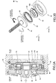
- the torque imparting device will be explained referring to Fig. 4A, Fig. 4B, and Fig. 4C respectively illustrating the spring 86, the rotor 84, and the stator 82 (only the body portion 88 being illustrated), Fig. 4D illustrating an exploded state of the torque imparting device 80 seen from a different viewpoint, and Fig. 4E illustrating a state in which the stator 82, the rotor 84, and the spring 86 are assembled into the torque imparting device 80.
- the stator 82 has a generally cylindrical shape and holds, at its rear portion, a circular support plate 92.
- a flanged cylindrical shaft 94 is attached to the support plate 92.
- the rotor 84 has a stepped hat-like shape, and a circular hole 96 is formed at a central portion of its front end. With the flanged cylindrical shaft 94 inserted into the circular hole 96, the rotor 84 is rotatably supported, in the stator 82, by the support plate 92 via a thrust bearing 98.
- a collar 100 is disposed between an outer circumference of the flanged cylindrical shaft 94 and an inner circumference of the thrust bearing 98.
- the flanged cylindrical shaft 94, the thrust bearing 98, and the collar 100 are not illustrated in Figs. 3B , 4D, and 4E .
- the support plate 92 is not illustrated in Fig. 3B .
- the spring 86 is a torsion coil spring (one example of a torsion spring) formed by winding, in a plurality of turns, a wire whose cross section is a quadrangle.
- One end portion 102 of the spring 86 located on a front-end side thereof, i.e., a portion of the spring 86 corresponding to a region indicated by the dashed line in Fig. 4A is bent at a plurality of locations (i.e., five locations) and has a shape similar to an outline of a regular hexagon. That is, the one end portion 102 of the spring 86 includes a plurality of bent portions 104, i.e., five bent portions 104, arranged on one circumference at a 60° pitch.
- a portion of the spring 86 located rearward of the one end portion 102 is a short cylindrical portion formed by winding the wire circularly.
- the five bent portions 104 protrude radially outward of the outer circumference of the cylindrical portion.
- the stator 82 has an opening 106 on its front-end side.
- the opening 106 is shaped like a regular hexagon whose vertexes are rounded. That is, six diametrically recessed portions 108 are arranged at a 60° pitch in the opening 106.
- the spring 86 is disposed in the stator 82 such that the one end portion 102 is fitted in the opening 106.
- the five bent portions 104 formed at the one end portion 102 of the spring 86 are retained by five of the six recessed portions 108 of the stator 82 as shown in Fig. 4E , whereby the spring 86 is prohibited from rotating relative to the stator 82 about the axis L. That is, each of the six recessed portions 108 of the stator 82 functions as a first retaining portion, and each of the five bent portions 104 of the spring 86 functions as a first retained portion to be retained by the first retaining portion.
- the spring 86 is disposed such that the cylindrical portion thereof is interposed between an inner circumferential wall of the stator 82 and an outer circumferential wall of the rotor 84.
- the other end portion of the spring 86 located on a rear-end side thereof includes, at its distal end, a first hook portion 110 inwardly bent into a hook-like shape.
- the rotor 84 has a cutout 112 formed by cutting a part of its circumferential wall.
- the first hook portion 110 of the spring 86 is retained by the cutout 112.
- the direction of rotation of the spring 86 and the rotor 84 about the axis L is defined as follows. As shown in Fig.
- a distal end of the one end portion 102 of the spring 86 is inwardly bent into a hook-like shape. That is, the one end portion 102 includes, at its distal end, a second hook portion 114.
- the rotor 84 includes, on its front-end side, a protruding portion 116 fixedly provided on its outer circumferential wall. The protruding portion 116 diametrically protrudes from a predetermined position, in the circumferential direction, of the outer circumferential wall of the rotor 84. In a state in which the protruding portion 116 is retained by the second hook portion 114, reverse rotation of the rotor 84 relative to the one end portion 102 of the spring 86 is prohibited.
- the spring 86 is in a state in which the spring 86 is twisted to a certain degree with respect to an unloaded state (natural state) in which no external force is acting on the spring 86. That is, the spring 86 is in a state in which the spring 86 can impart, to the rotor 84, an elastic torque in a direction to rotate the rotor 84 reversely.
- the elastic torque may be referred to as a set torque (pre-torque) set as a lower limit of the elastic torque to be generated by the spring 86.
- the protruding portion 116 of the rotor 84 and the second hook portion 114 provided at the one end portion 102 of the spring 86 constitute a lower-limit torque ensuring mechanism configured to prohibit the elastic torque of the spring 86 from becoming smaller than the set lower-limit torque.
- the first hook portion 110 of the other end portion of the spring 86 functions as a third retained portion
- the cutout 112 of the rotor 84 functions as a third retaining portion to retain the third retained portion.
- the cutout 112 has a circumferential dimension larger than that of the first hook portion 110.
- the spring 86 is untwisted to a certain degree, so that the rotor 84 is rotated in the reverse rotational direction by an elastic reaction force of the spring 86, and the protruding portion 116 of the rotor 84 is retained by the second hook portion 114 of the one end portion 102 of the spring 86.
- the rotor 84 and the spring 86 can be easily mounted to the stator 82 with the elastic torque as the set lower-limit torque maintained.
- the forward rotation of the input shaft 56 by the electric motor 44 causes the piston 42 to be advanced and causes the brake pads 28 to be pushed onto the disc rotor 22, so that the braking force is generated.
- the input shaft 56 receives a reaction force of a pushing force by which the brake pads 28 are pushed onto the disc rotor 22, as indicated by a white arrow in Fig. 3A .
- the rear end face 120 of the input shaft 56 and the front end face 122 of the rotor 84 come into contact with each other so as to be pushed onto each other, so that a friction force is generated between the rear end face 120 and the front end face 122.
- the torque imparting device 80 includes a clutch mechanism utilizing friction and constituted by the front end face 122 of the rotor 84 and the rear end face 120 of the input shaft 56.
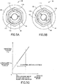
- the state of the torque imparting device 80 is changed from a state shown in Fig. 5A at a start time point of generation of the braking force to a state shown in Fig. 5B .
- the rotor 84 starts rotating forwardly, the retaining of the protruding portion 116 of the rotor 84 by the second hook portion 114 of the spring 86 is cancelled.
- the spring 86 is further twisted by an amount corresponding to the amount of the forward rotation of the rotor 84 while the first hook portion 110 of the spring 86 is kept retained by the cutout 112 of the rotor 84. That is, the elastic torque of the spring 86 increases by a magnitude corresponding to the amount of the forward rotation of the rotor 84.
- This elastic torque acts on the input shaft 56 as a torque in a direction in which the piston 42 is retracted, namely, as a torque in the reverse rotational direction.
- the torque that acts on the input shaft 56 is referred to as an imparting torque.
- the piston 42 is advanced against the imparting torque after the braking force has been generated.
- the forward rotational amount of the rotor 84 and an amount of the advancing movement of the piston 42 are proportional, and a relationship between the piston advancing amount and the imparting torque is represented by a graph of Fig. 5C .
- the piston advancing amount X increases and becomes equal to an advancing amount X 0 at the start time point of braking force generation (that is an amount of the advancing movement of the piston 42 at the time point when the braking force starts to be generated)
- the braking force starts to be generated and thereafter increases with an increase in the piston advancing amount X.
- the spring 86 exerts the set lower-limit torque owing to the lower-limit torque ensuring mechanism.
- a lower-limit imparting torque Tq 0 as the imparting torque Tq, corresponding to the set lower-limit torque. From then onwards, the imparting torque Tq increases in proportion to the piston advancing amount X.
- the magnitude of the braking force being generated depends on the elastic deformation amount of the brake pads 28. Accordingly, the magnitude of the braking force being generated is generally proportional to the piston advancing amount X increased from the advancing amount X 0 if wear of the brake pads 28 is not taken into consideration.
- the input shaft 56 is also reversely rotated.
- the imparting torque Tq decreases to a value at a time point when the protruding portion 116 of the rotor 84 is retained by the second hook portion 114 of the spring 86, namely, the imparting torque Tq decreases to the lower-limit imparting torque Tq 0 .
- the state of the torque imparting device 80 at this time point is the state shown in Fig. 5A . If wear or the like of the brake pads 28 is not taken into consideration, the braking force is no longer generated at the time point in question in a theoretical sense.
- the electric motor 44 fails to operate, specifically, the electric motor 44 fails to exert a force, in a state in which the braking force is being generated. If the actuator 10 is not equipped with the torque imparting device 80, the piston 42 cannot be easily retracted in the situation in which the electric motor 44 fails to exert a force in the reverse rotational direction because of comparatively low negative efficiency (reverse efficiency) of the motion converting mechanism 64 constituted by the nut 60 and the input shaft 56 with the external threads. In an extreme case, the brake pads 28 are kept pushed onto the disc rotor 22, making it impossible to decrease the braking force being generated. That is, the drag state continues.
- the present torque imparting device 80 exerts its effect in the situation in which the electric motor 44 cannot exert the force in the reverse rotational direction. Specifically, as long as the braking force is being generated, namely, as long as the rotor 84 and the input shaft 56 are rotatable together as a unit, the imparting torque Tq in the reverse rotational direction that depends on the elastic torque of the spring 86 is acting on the input shaft 56. Accordingly, even if the electric motor 44 cannot exert the force in the reverse rotational direction, the piston 42 can be retracted by the imparting torque Tq so as to cancel the braking force. That is, the vehicle is prevented from running with the braking force kept generated.
- the imparting torque Tq not smaller than the lower-limit imparting torque Tq 0 is imparted to the input shaft 56 all the time in the state in which the braking force is being generated.
- This configuration enables the piston 42 to be smoothly retracted to the position at which the braking force is not generated, without depending on the force of the electric motor 44.
- the piston 42 can be retracted with high reliability even if the electric motor 44 fails to operate in the state in which the braking force is being generated.
- the present torque imparting device 80 employs the spring 86 formed by a wire whose cross section is a square, and the spring 86 has a larger cross-sectional area, as compared with a spring formed by a wire whose cross section is a circle.
- the spring 86 can generate a comparatively large elastic torque, so that the present torque imparting device 80 has a reduced size, as compared with a torque imparting device that employs the spring formed by the wire having a circular cross section.
- the braking force expected to be generated in a normal brake operation is a maximum braking force. Because the braking force is proportional to the elastic deformation amount of the brake pads 28, it is expected that the piston 42 is moved, in the normal brake operation, within a region of a normal moving distance ⁇ X indicated in a graph of Fig. 5C . Settings of the torque imparting device 80 are made such that the imparting torque Tq takes a necessary and sufficient value in the region. It is, however, expected that one brake operation continues for a long time when the vehicle is running on a long downward slope, for instance. That is, a situation is expected in which the driver holds the brake pedal down. In such a situation, the brake pads 28 are largely worn.
- the piston advancing amount X will considerably increase beyond the normal moving distance ⁇ X.
- the increase in the piston advancing amount X in turn causes an increase in the imparting torque Tq by the torque imparting device 80. That is, the spring 86 of the torque imparting device 80 is twisted to a considerably large extent, resulting in an excessively large load on the torque imparting device 80.
- the spring 86 is a torsion coil spring, the spring 86 may be possibly twisted beyond its structural limitations.
- the piston 42 needs to be advanced against an excessively large imparting torque Tq, and the electric motor 44 may undesirably receive an excessive load. Not only the large wear of the brake pads 28 but also the increase in the imparting torque Tq and the excessive elastic deformation of the spring 86 may undesirably cause various problems to the torque imparting device 80 and the actuator 10.
- the present torque imparting device 80 is equipped with a retained-position-change allowing mechanism.
- the spring 86 of the torque imparting device 80 is disposed in the stator 82 such that the five bent portions 104 provided at the one end portion 102 thereof are retained by respective five of the six recessed portions 108 of the stator 82.
- the elastic torque exceeds a specific value, i.e., the set upper-limit torque
- each of the five bent portions 104 is retained by another corresponding one of the recessed portions 108 different from one recessed portion 108 by which the bent portion 104 has been retained so far.
- a specific value i.e., the set upper-limit torque
- the one end portion 102 of the spring 86 is caused to be elastically deformed with its diameter being reduced as shown in Fig. 6B . That is, the one end portion 102 is elastically deformed such that the bent portions 104 get closer to the axis L.
- Such elastic deformation causes each bent portion 104 to slide on the inner circumferential surface of the opening 106 of the stator 82 by the elastic torque of the spring 86, so that retaining of the bent portion 104 by the recessed portion 108 that currently retains the bent portion 104 is canceled, and the bent portion 104 is newly retained by another recessed portion 108 located next to that the recessed portion 108 in the forward rotational direction, as shown in Fig. 6C .
- the retained-position-change allowing mechanism is constituted by the bent portions 104 each as the first retained portion and the recessed portions 108 each as the first retaining portion and is configured to allow each bent portion 104 to be retained by another recessed portion 108 different from the recessed portion 108 by which the bent portion 104 has been retained so far.
- the retained-position-change allowing mechanism is configured to allow a change of the position at which each first retained portion is retained.
- the retained-position-change allowing mechanism allows each bent portion 104 to be retained by another recessed portion 108 as described above, so that the spring 86 is untwisted by an amount corresponding to the change of the retained positions, and the elastic torque is accordingly decreased.
- the imparting torque Tq is decreased.
- the imparting torque Tq changes as indicated in a graph of Fig. 7 with an increase in the piston advancing amount X.
- the graph indicates an instance in which the elastic torque exceeds, three times, the set upper-limit torque (that is a torque corresponding to an upper-limit imparting torque Tq1 in the graph) and the retained-position-change allowing mechanism operates three times.
- the piston 42 is retracted by an amount in accordance with the braking force that has been generated by the electric brake device 20 before proceeding to the decreasing process of the braking force. After the piston 42 has been retracted, the braking force is no longer generated.
- This operation is the same irrespective of whether or not the retained-position-change allowing mechanism works in one brake operation as indicated in the graph of Fig. 7 . Assuming that the piston 42 is advanced to a position marked with " ⁇ " in the graph and the brake operation is ended, the piston 42 is retracted in the decreasing process of the braking force, as indicated by the dashed line in the graph.
- the input shaft 56 and the rotor 84 are allowed to rotate relative to each other.
- the rotor 84 is rotated by the decreased elastic torque, the protruding portion 116 of the rotor 84 is retained by the second hook portion 114 of the spring 86, and the elastic torque becomes equal to the set lower-limit torque. That is, the imparting torque Tq becomes equal to the lower-limit imparting torque Tq 0 .
- the graph indicates a case in which the braking force becomes equal to 0 before the protruding portion 116 is retained by the second hook portion 114.
- the lower-limit torque ensuring mechanism enables the imparting torque Tq not smaller than the lower-limit imparting torque Tq 0 to be stably imparted to the input shaft 56 in brake operations subsequent to that brake operation.
- the piston 42 can be retracted with high reliability.
- the retained-position-change allowing mechanism in the illustrated embodiment is constituted by the five bent portions 104, each as the first retained portion, provided at the one end portion 102 of the spring 86 and the six recessed portions 108, each as the first retaining portion, provided in the stator 82 so as to be arranged on one circumference. That is, the actuator 10 according to the illustrated embodiment employs the retained-position-change allowing mechanism including a plurality of first retained portions and a plurality of first retaining portions. In place of the retained-position-change allowing mechanism, a retained-position-change allowing mechanism including only one first retained portion may be employed, so as to construct an actuator according to a modification, as explained below.
- the modified retained-position-change allowing mechanism shown in Fig. 8A includes the six recessed portions 108, each as the first retaining portion, provided in the stator 82.
- the modified retained-position-change allowing mechanism includes only one bent portion 104', as the first retained portion, provided at one end portion 102' of the spring 86'.
- the imparting torque not smaller than the lower-limit imparting torque Tq 0 can be imparted to the input shaft 56 by the lower-limit torque ensuring mechanism while preventing the elastic torque from exceeding the set upper-limit torque.
- the outside diameter of the spring 86' that is a torsion coil spring becomes smaller with an increase in the elastic torque, namely, with an increase in its torsion amount (twisted amount).
- the axis of the spring 86' may be inclined relative to the axis L of the actuator 10 or may be diametrically shifted or offset relative to the axis L because the only one bent portion 104' is retained.
- the only one bent portion 104' is provided at the distal end of the one end portion 102', so that the front-side portion of the spring 86' is largely shifted in a direction indicated by the white arrow in Fig. 8A .
- the bent portion 104' as the first retained portion may fail to be stably retained. In other words, it is expected that the bent portion 104' easily slips off from the recessed portion 108 as the first retaining portion.
- the retained-position-change allowing mechanism of the actuator 10 includes the five bent portions 104 arranged on one circumference of the one end portion 102 of the spring 86 as shown in Fig. 8B , in other words, the plurality of first retained portions are respectively retained by the plurality of first retaining portions.
- the present retained-position-change allowing mechanism is free from the inclination of the axis of the spring 86 relative to the axis L of the actuator 10 or the offset of the axis of the spring 86 relative to the axis L of the actuator 10. This will be more specifically explained referring to Fig. 8B .
- Positions at which the plurality of bent portions 104 are retained are referred to retained positions 124a-124e as shown in Fig.
- the retained positions 124a-124e include groups of the retained positions equiangularly arranged on one circumference. Specifically, the retained positions 124a-124e include a group of the retained positions arranged at a 120° pitch (i.e. the retained positions 124a, 124c, 124e) and two groups of the retained positions arranged at a 180° pitch (i.e., the retained positions 124a, 124d and the retained positions 124b, 124e).
- This configuration effectively prevents or reduces an occurrence of the inclination or the offset of the axis of the spring 86 described above.
Landscapes
- Engineering & Computer Science (AREA)
- General Engineering & Computer Science (AREA)
- Mechanical Engineering (AREA)
- Transportation (AREA)
- Braking Arrangements (AREA)
- Springs (AREA)
- Braking Systems And Boosters (AREA)
Claims (8)
- Elektrischer Bremsaktuator, der dazu gestaltet ist, ein Reibungselement (26) an einen Drehkörper (22) zu drücken, der sich zusammen mit einem Rad dreht, umfassend:einen Hauptkörper (40),einen Kolben (42), der durch den Hauptkörper derart gehalten wird, dass er vorrückbar und rückziehbar ist, wobei der Kolben (42) dazu gestaltet ist, das Reibungselement (26) durch Vorrücken zu dem Drehkörper (22) hin zu drücken,einen Elektromotor (44),einen Bewegungsumwandlungsmechanismus (64), der eine Antriebswelle (56) beinhaltet, die dazu gestaltet ist, von dem Elektromotor (44) gedreht zu werden, wobei der Bewegungsumwandlungsmechanismus dazu gestaltet ist, eine Drehbewegung des Elektromotors (44) in eine vorrückende und eine zurückziehende Bewegung des Kolbens (42) umzuwandeln, undeine Drehmoment verleihende Vorrichtung (80; 80'), die eine Torsionsfeder (86; 86') beinhaltet und dazu gestaltet ist, der Antriebswelle (56) ein Drehmoment in eine Richtung zu verleihen, in die sich der Kolben (42) zurückzieht, in Abhängigkeit von einem elastischen Drehmoment, das durch die Torsionsfeder (86; 86') erzeugt wird,wobei die Drehmoment verleihende Vorrichtung (80; 80') Folgendes beinhaltet:einen Stator (82), der an dem Hauptkörper (40) befestigt ist und dazu gestaltet ist, durch einen einer Mehrzahl von ersten Halteabschnitten (108) davon einen ersten gehaltenen Abschnitt (104; 104') zu halten, der an einem Endabschnitt (102; 102') der Torsionsfeder (86; 86') bereitgestellt ist,einen Rotor (84), der den anderen Endabschnitt der Torsionsfeder (86; 86') hält und dazu gestaltet ist, die Torsionsfeder (86; 86') durch seine Drehung zu verdrehen, undeinen Mechanismus, der das Ändern der gehaltenen Position ermöglicht (104, 108; 104', 108), der dazu gestaltet ist, es zu ermöglichen, dass der erste gehaltene Abschnitt (104; 104'), der an dem einen Endabschnitt (102; 102') der Torsionsfeder (86; 86') bereitgestellt ist, durch einen anderen der Mehrzahl erster Halteabschnitte (108) des Stators (82) gehalten wird, wenn das elastische Drehmoment der Torsionsfeder (86; 86') ein eingestelltes Obergrenzen-Drehmoment überschreitet, damit das elastische Drehmoment verringert wird,dadurch gekennzeichnet, dassdie Drehmoment verleihende Vorrichtung (80; 80') ferner Folgendes beinhaltet:einen das Untergrenzen-Drehmoment gewährleistenden Mechanismus (114, 116), der dazu gestaltet ist, es zu gestatten, dass ein zweiter gehaltener Abschnitt (116), der an dem Rotor (84) bereitgestellt ist, durch einen zweiten Halteabschnitt (114) gehalten wird, der an dem anderen Endabschnitt (102; 102') der Torsionsfeder (86; 86') bereitgestellt ist, damit verhindert wird, dass das elastische Drehmoment der Torsionsfeder kleiner wird als ein eingestelltes Untergrenzen-Drehmoment, undeinen Kupplungsmechanismus, der dazu gestaltet ist, es zu ermöglichen, dass sich der Rotor und die Antriebswelle in einem Zustand, in dem die Antriebswelle eine Reaktionskraft einer Drückkraft empfängt, durch die der Kolben das Reibungselement an den Drehkörper drückt, als eine Einheit zusammen in Bezug auf den Stator zu drehen, und es zu ermöglichen, dass sich der Rotor und die Antriebswelle in einem Zustand, in dem die Antriebswelle die Reaktionskraft nicht empfängt, im Verhältnis zueinander zu drehen.
- Elektrischer Bremsaktuator nach Anspruch 1, wobei die Torsionsfeder (86; 86') eine Torsionsspiralfeder ist, die durch Wickeln eines Drahtes in einer Mehrzahl von Windungen gebildet ist.
- Elektrischer Bremsaktuator nach Anspruch 2, wobei die Torsionsspiralfeder (86; 86') durch Wickeln des Drahtes, dessen Querschnitt ein Quadrat ist, in einer Mehrzahl von Windungen gebildet ist.
- Elektrischer Bremsaktuator nach Anspruch 2 oder 3, wobei der erste gehaltene Abschnitt (104; 104') durch Biegen des Drahtes an dem einen Endabschnitt (102; 102') der Torsionsfeder (86; 86') gebildet ist und jeder der Mehrzahl von ersten Halteabschnitten (108) als vertiefter Abschnitt gebildet ist, der in der Lage ist, den ersten gehaltenen Abschnitt (104; 104') zu halten.
- Elektrischer Bremsaktuator nach einem der Ansprüche 1 bis 4, wobei der Mechanismus, der das Ändern der gehaltenen Position ermöglicht (104, 108; 104', 108) dazu gestaltet ist, es zu ermöglichen, dass der ersten gehaltene Abschnitt (104; 104') durch den anderen der Mehrzahl von ersten Halteabschnitten (108) gehalten zu werden, statt den ersten gehaltenen Abschnitt (104; 104') mit dem einen der Mehrzahl von ersten Halteabschnitten (108) zu halten, aufgrund einer Bewegung des ersten gehaltenen Abschnitts (104; 104'), der an dem einen Endabschnitt (102; 102') der Torsionsfeder (86; 86') bereitgestellt ist, die durch elastische Verformung des einen Endabschnitts (102; 102') mit einer Erhöhung des elastischen Drehmoments der Torsionsfeder (86; 86') bewirkt wird.
- Elektrischer Bremsaktuator nach einem der Ansprüche 1 bis 5, wobei die Mehrzahl der ersten Halteabschnitte (108) an einem Umfang des Stators (82) bereitgestellt ist und eine Mehrzahl erster gehaltener Abschnitte (104), jeder als der erste gehaltene Abschnitt, an einem Umfang des anderen Endabschnitts (102) der Torsionsfeder (86) angeordnet ist.
- Elektrischer Bremsaktuator nach Anspruch 6,
wobei, wenn eine Position, an der jeder der Mehrzahl von ersten gehaltenen Abschnitten (104) durch einen entsprechenden der Mehrzahl von ersten Halteabschnitten gehalten wird, als eine gehaltene Position definiert ist, der elektrische Bremsaktuator eine Mehrzahl von gehaltenen Positionen beinhaltet, und
wobei mindestens zwei der Mehrzahl von gehaltenen Positionen in einem gleichwinkligen Abstand angeordnet sind. - Elektrischer Bremsaktuator nach einem der Ansprüche 1 bis 7, wobei der Rotor (84) einen Ausschnitt (112) als einen dritten Halteabschnitt beinhaltet, in den ein dritter gehaltener Abschnitt (110) eingesetzt ist, der an dem anderen Endabschnitt der Torsionsfeder (86; 86') bereitgestellt ist, damit der andere Endabschnitt gehalten wird, und der Ausschnitt (112) eine Umfangsabmessung aufweist, die größer ist als die des dritten gehaltenen Abschnitts (110).
Applications Claiming Priority (1)
| Application Number | Priority Date | Filing Date | Title |
|---|---|---|---|
| JP2018052707A JP6965802B2 (ja) | 2018-03-20 | 2018-03-20 | 電動ブレーキアクチュエータ |
Publications (2)
| Publication Number | Publication Date |
|---|---|
| EP3550170A1 EP3550170A1 (de) | 2019-10-09 |
| EP3550170B1 true EP3550170B1 (de) | 2021-08-18 |
Family
ID=65903940
Family Applications (1)
| Application Number | Title | Priority Date | Filing Date |
|---|---|---|---|
| EP19163709.9A Active EP3550170B1 (de) | 2018-03-20 | 2019-03-19 | Elektrischer bremsaktuator |
Country Status (5)
| Country | Link |
|---|---|
| US (1) | US11098778B2 (de) |
| EP (1) | EP3550170B1 (de) |
| JP (1) | JP6965802B2 (de) |
| KR (1) | KR102202552B1 (de) |
| CN (1) | CN110307275B (de) |
Families Citing this family (8)
| Publication number | Priority date | Publication date | Assignee | Title |
|---|---|---|---|---|
| JP7131329B2 (ja) * | 2018-11-21 | 2022-09-06 | トヨタ自動車株式会社 | ブレーキアクチュエータ |
| JP7047788B2 (ja) * | 2019-01-28 | 2022-04-05 | トヨタ自動車株式会社 | 電動ブレーキアクチュエータ |
| KR102773638B1 (ko) * | 2020-01-30 | 2025-02-28 | 에이치엘만도 주식회사 | 브레이크장치용 엑츄에이터 및 이를 갖는 브레이크 장치 |
| US11745714B2 (en) * | 2021-04-09 | 2023-09-05 | GM Global Technology Operations LLC | System for electronic parking brake actuation |
| KR102477442B1 (ko) * | 2021-08-19 | 2022-12-13 | 하이윈 테크놀로지스 코포레이션 | 상시 폐쇄식 제동 장치 및 이를 사용하는 로터리 테이블 |
| CN116771822B (zh) * | 2022-03-07 | 2025-12-23 | 芜湖伯特利汽车安全系统股份有限公司 | 电控机械干式制动钳 |
| IT202200026679A1 (it) * | 2022-12-23 | 2024-06-23 | Brembo Spa | Attuatore elettroidraulico per freno |
| KR20250006578A (ko) * | 2023-07-04 | 2025-01-13 | 현대모비스 주식회사 | 전동식 브레이크 및 그 제어방법 |
Family Cites Families (18)
| Publication number | Priority date | Publication date | Assignee | Title |
|---|---|---|---|---|
| US3767016A (en) * | 1972-10-30 | 1973-10-23 | Gen Motors Corp | Brake actuator and adjuster mechanism |
| GB2074670B (en) * | 1980-04-22 | 1983-08-17 | Lucas Industries Ltd | Actuator mechanism for vehicle brakes |
| DE19511287B4 (de) * | 1994-07-21 | 2004-05-06 | Continental Teves Ag & Co. Ohg | Elektromechanische betätigbare Scheibenbremse |
| DE102005046804A1 (de) * | 2005-01-18 | 2006-08-17 | Continental Teves Ag & Co. Ohg | Teilbelag-Scheibenbremse |
| JP4640266B2 (ja) * | 2006-06-07 | 2011-03-02 | 株式会社アドヴィックス | 電動パーキングブレーキ装置 |
| US9732813B2 (en) * | 2006-12-29 | 2017-08-15 | Haldex Brake Products Ab | Park lock and pad wear adjusting arrangement for electrically actuated brake |
| DE102007046953A1 (de) * | 2007-10-01 | 2009-04-02 | Lucas Automotive Gmbh | Kugelgewindetrieb für eine Kraftfahrzeugbremse und Kraftfahrzeugbremse |
| DE102009006290A1 (de) * | 2009-01-27 | 2010-07-29 | Knorr-Bremse Systeme für Schienenfahrzeuge GmbH | Verbindung eines Bremsbelages mit einem Belaghalter |
| CN101571169B (zh) * | 2009-06-03 | 2011-02-16 | 奇瑞汽车股份有限公司 | 一种盘式制动器 |
| KR101317152B1 (ko) * | 2009-11-30 | 2013-10-11 | 주식회사 만도 | 디스크 브레이크 |
| CN102011816B (zh) * | 2010-12-01 | 2012-08-29 | 东风汽车有限公司 | 一种具有摩擦块回位结构的盘式制动器 |
| DE102010063320A1 (de) * | 2010-12-17 | 2012-06-21 | Continental Teves Ag & Co. Ohg | Elektromechanisch betätigbare Bremse und Verfahren zum Betreiben einer elektromechanisch betätigbaren Bremse |
| JP5760800B2 (ja) * | 2011-07-25 | 2015-08-12 | 株式会社アドヴィックス | 車両用電動ブレーキ装置 |
| KR101331783B1 (ko) * | 2012-09-10 | 2013-11-21 | 주식회사 만도 | 주차기능을 갖는 전자식 캘리퍼 브레이크 |
| KR102228030B1 (ko) * | 2014-07-31 | 2021-03-15 | 히다치 아스테모 가부시키가이샤 | 디스크 브레이크 |
| US9527584B2 (en) * | 2015-01-16 | 2016-12-27 | Goodrich Corporation | Electromechanically actuated brake with supplemental back drive |
| KR101876006B1 (ko) * | 2015-12-10 | 2018-08-02 | 현대자동차주식회사 | 코깅 토크 저감장치를 가진 전동식 브레이크 |
| KR101786337B1 (ko) * | 2016-04-29 | 2017-10-17 | 현대자동차주식회사 | 전동식 브레이크 |
-
2018
- 2018-03-20 JP JP2018052707A patent/JP6965802B2/ja not_active Expired - Fee Related
-
2019
- 2019-02-28 CN CN201910149602.6A patent/CN110307275B/zh not_active Expired - Fee Related
- 2019-03-18 US US16/356,070 patent/US11098778B2/en not_active Expired - Fee Related
- 2019-03-19 KR KR1020190031158A patent/KR102202552B1/ko not_active Expired - Fee Related
- 2019-03-19 EP EP19163709.9A patent/EP3550170B1/de active Active
Non-Patent Citations (1)
| Title |
|---|
| None * |
Also Published As
| Publication number | Publication date |
|---|---|
| JP2019163831A (ja) | 2019-09-26 |
| JP6965802B2 (ja) | 2021-11-10 |
| EP3550170A1 (de) | 2019-10-09 |
| CN110307275A (zh) | 2019-10-08 |
| US11098778B2 (en) | 2021-08-24 |
| KR102202552B1 (ko) | 2021-01-13 |
| CN110307275B (zh) | 2022-04-12 |
| US20190293134A1 (en) | 2019-09-26 |
| KR20190110468A (ko) | 2019-09-30 |
Similar Documents
| Publication | Publication Date | Title |
|---|---|---|
| US11098778B2 (en) | Electric brake actuator | |
| US11428301B2 (en) | Motion conversion mechanism and electric brake actuator including the same | |
| EP3657039B1 (de) | Bremszylinder | |
| US20200240485A1 (en) | Electric brake actuator | |
| CN105317894B (zh) | 盘式制动器 | |
| CN108177642B (zh) | 电动式直动致动器以及电动制动装置 | |
| JP5471206B2 (ja) | 駆動ユニット | |
| US8474579B2 (en) | Electromotive brake system | |
| CN1114770C (zh) | 具有小型齿轮减速机构的致动器 | |
| JP7040287B2 (ja) | 車両用ブレーキ装置 | |
| JP2003519764A (ja) | アクチュエータユニットおよびブレーキキャリパ | |
| US11174919B2 (en) | Speed reduction device and brake actuator including ihe same | |
| CN1387614A (zh) | 具有套筒支撑件的致动器 | |
| JP4304418B2 (ja) | 電動ディスクブレーキ | |
| CN115199676A (zh) | 用于电子停车制动器致动的系统 | |
| JP6483567B2 (ja) | 電動パーキングブレーキ | |
| JP2018062989A (ja) | 電動ブレーキアクチュエータ | |
| JP4288501B2 (ja) | 電動ブレーキ装置 | |
| JP2005133863A (ja) | 制動装置 | |
| CN108782487B (zh) | 旋压式绕线轮 | |
| JP4061584B2 (ja) | 電動ディスクブレーキ | |
| CN109501781A (zh) | 一种消除液压盘式制动器启动阻滞的方法 | |
| JP2002257165A (ja) | 電動ディスクブレーキ | |
| JP2021059239A (ja) | 電動ブレーキ | |
| JP2000283194A (ja) | 電動式ブレーキ装置 |
Legal Events
| Date | Code | Title | Description |
|---|---|---|---|
| PUAI | Public reference made under article 153(3) epc to a published international application that has entered the european phase |
Free format text: ORIGINAL CODE: 0009012 |
|
| STAA | Information on the status of an ep patent application or granted ep patent |
Free format text: STATUS: REQUEST FOR EXAMINATION WAS MADE |
|
| 17P | Request for examination filed |
Effective date: 20190419 |
|
| AK | Designated contracting states |
Kind code of ref document: A1 Designated state(s): AL AT BE BG CH CY CZ DE DK EE ES FI FR GB GR HR HU IE IS IT LI LT LU LV MC MK MT NL NO PL PT RO RS SE SI SK SM TR |
|
| AX | Request for extension of the european patent |
Extension state: BA ME |
|
| GRAP | Despatch of communication of intention to grant a patent |
Free format text: ORIGINAL CODE: EPIDOSNIGR1 |
|
| STAA | Information on the status of an ep patent application or granted ep patent |
Free format text: STATUS: GRANT OF PATENT IS INTENDED |
|
| RIC1 | Information provided on ipc code assigned before grant |
Ipc: F16D 65/18 20060101AFI20200624BHEP |
|
| INTG | Intention to grant announced |
Effective date: 20200722 |
|
| GRAJ | Information related to disapproval of communication of intention to grant by the applicant or resumption of examination proceedings by the epo deleted |
Free format text: ORIGINAL CODE: EPIDOSDIGR1 |
|
| STAA | Information on the status of an ep patent application or granted ep patent |
Free format text: STATUS: REQUEST FOR EXAMINATION WAS MADE |
|
| INTC | Intention to grant announced (deleted) | ||
| GRAP | Despatch of communication of intention to grant a patent |
Free format text: ORIGINAL CODE: EPIDOSNIGR1 |
|
| STAA | Information on the status of an ep patent application or granted ep patent |
Free format text: STATUS: GRANT OF PATENT IS INTENDED |
|
| GRAJ | Information related to disapproval of communication of intention to grant by the applicant or resumption of examination proceedings by the epo deleted |
Free format text: ORIGINAL CODE: EPIDOSDIGR1 |
|
| GRAP | Despatch of communication of intention to grant a patent |
Free format text: ORIGINAL CODE: EPIDOSNIGR1 |
|
| GRAJ | Information related to disapproval of communication of intention to grant by the applicant or resumption of examination proceedings by the epo deleted |
Free format text: ORIGINAL CODE: EPIDOSDIGR1 |
|
| GRAP | Despatch of communication of intention to grant a patent |
Free format text: ORIGINAL CODE: EPIDOSNIGR1 |
|
| INTG | Intention to grant announced |
Effective date: 20210127 |
|
| RIN1 | Information on inventor provided before grant (corrected) |
Inventor name: NANAHARA, MASAKI Inventor name: YABUSAKI, NAOKI Inventor name: MORIKAWA, YUTA |
|
| GRAJ | Information related to disapproval of communication of intention to grant by the applicant or resumption of examination proceedings by the epo deleted |
Free format text: ORIGINAL CODE: EPIDOSDIGR1 |
|
| GRAP | Despatch of communication of intention to grant a patent |
Free format text: ORIGINAL CODE: EPIDOSNIGR1 |
|
| INTG | Intention to grant announced |
Effective date: 20210212 |
|
| INTG | Intention to grant announced |
Effective date: 20210224 |
|
| INTG | Intention to grant announced |
Effective date: 20210311 |
|
| GRAS | Grant fee paid |
Free format text: ORIGINAL CODE: EPIDOSNIGR3 |
|
| GRAA | (expected) grant |
Free format text: ORIGINAL CODE: 0009210 |
|
| STAA | Information on the status of an ep patent application or granted ep patent |
Free format text: STATUS: THE PATENT HAS BEEN GRANTED |
|
| AK | Designated contracting states |
Kind code of ref document: B1 Designated state(s): AL AT BE BG CH CY CZ DE DK EE ES FI FR GB GR HR HU IE IS IT LI LT LU LV MC MK MT NL NO PL PT RO RS SE SI SK SM TR |
|
| REG | Reference to a national code |
Ref country code: GB Ref legal event code: FG4D |
|
| REG | Reference to a national code |
Ref country code: CH Ref legal event code: EP |
|
| REG | Reference to a national code |
Ref country code: DE Ref legal event code: R096 Ref document number: 602019006888 Country of ref document: DE |
|
| REG | Reference to a national code |
Ref country code: IE Ref legal event code: FG4D Ref country code: AT Ref legal event code: REF Ref document number: 1421914 Country of ref document: AT Kind code of ref document: T Effective date: 20210915 |
|
| REG | Reference to a national code |
Ref country code: LT Ref legal event code: MG9D |
|
| REG | Reference to a national code |
Ref country code: NL Ref legal event code: MP Effective date: 20210818 |
|
| REG | Reference to a national code |
Ref country code: AT Ref legal event code: MK05 Ref document number: 1421914 Country of ref document: AT Kind code of ref document: T Effective date: 20210818 |
|
| PG25 | Lapsed in a contracting state [announced via postgrant information from national office to epo] |
Ref country code: HR Free format text: LAPSE BECAUSE OF FAILURE TO SUBMIT A TRANSLATION OF THE DESCRIPTION OR TO PAY THE FEE WITHIN THE PRESCRIBED TIME-LIMIT Effective date: 20210818 Ref country code: NO Free format text: LAPSE BECAUSE OF FAILURE TO SUBMIT A TRANSLATION OF THE DESCRIPTION OR TO PAY THE FEE WITHIN THE PRESCRIBED TIME-LIMIT Effective date: 20211118 Ref country code: PT Free format text: LAPSE BECAUSE OF FAILURE TO SUBMIT A TRANSLATION OF THE DESCRIPTION OR TO PAY THE FEE WITHIN THE PRESCRIBED TIME-LIMIT Effective date: 20211220 Ref country code: LT Free format text: LAPSE BECAUSE OF FAILURE TO SUBMIT A TRANSLATION OF THE DESCRIPTION OR TO PAY THE FEE WITHIN THE PRESCRIBED TIME-LIMIT Effective date: 20210818 Ref country code: BG Free format text: LAPSE BECAUSE OF FAILURE TO SUBMIT A TRANSLATION OF THE DESCRIPTION OR TO PAY THE FEE WITHIN THE PRESCRIBED TIME-LIMIT Effective date: 20211118 Ref country code: AT Free format text: LAPSE BECAUSE OF FAILURE TO SUBMIT A TRANSLATION OF THE DESCRIPTION OR TO PAY THE FEE WITHIN THE PRESCRIBED TIME-LIMIT Effective date: 20210818 Ref country code: FI Free format text: LAPSE BECAUSE OF FAILURE TO SUBMIT A TRANSLATION OF THE DESCRIPTION OR TO PAY THE FEE WITHIN THE PRESCRIBED TIME-LIMIT Effective date: 20210818 Ref country code: ES Free format text: LAPSE BECAUSE OF FAILURE TO SUBMIT A TRANSLATION OF THE DESCRIPTION OR TO PAY THE FEE WITHIN THE PRESCRIBED TIME-LIMIT Effective date: 20210818 Ref country code: RS Free format text: LAPSE BECAUSE OF FAILURE TO SUBMIT A TRANSLATION OF THE DESCRIPTION OR TO PAY THE FEE WITHIN THE PRESCRIBED TIME-LIMIT Effective date: 20210818 Ref country code: SE Free format text: LAPSE BECAUSE OF FAILURE TO SUBMIT A TRANSLATION OF THE DESCRIPTION OR TO PAY THE FEE WITHIN THE PRESCRIBED TIME-LIMIT Effective date: 20210818 |
|
| PG25 | Lapsed in a contracting state [announced via postgrant information from national office to epo] |
Ref country code: PL Free format text: LAPSE BECAUSE OF FAILURE TO SUBMIT A TRANSLATION OF THE DESCRIPTION OR TO PAY THE FEE WITHIN THE PRESCRIBED TIME-LIMIT Effective date: 20210818 Ref country code: LV Free format text: LAPSE BECAUSE OF FAILURE TO SUBMIT A TRANSLATION OF THE DESCRIPTION OR TO PAY THE FEE WITHIN THE PRESCRIBED TIME-LIMIT Effective date: 20210818 Ref country code: GR Free format text: LAPSE BECAUSE OF FAILURE TO SUBMIT A TRANSLATION OF THE DESCRIPTION OR TO PAY THE FEE WITHIN THE PRESCRIBED TIME-LIMIT Effective date: 20211119 |
|
| PG25 | Lapsed in a contracting state [announced via postgrant information from national office to epo] |
Ref country code: NL Free format text: LAPSE BECAUSE OF FAILURE TO SUBMIT A TRANSLATION OF THE DESCRIPTION OR TO PAY THE FEE WITHIN THE PRESCRIBED TIME-LIMIT Effective date: 20210818 |
|
| PG25 | Lapsed in a contracting state [announced via postgrant information from national office to epo] |
Ref country code: DK Free format text: LAPSE BECAUSE OF FAILURE TO SUBMIT A TRANSLATION OF THE DESCRIPTION OR TO PAY THE FEE WITHIN THE PRESCRIBED TIME-LIMIT Effective date: 20210818 |
|
| PGFP | Annual fee paid to national office [announced via postgrant information from national office to epo] |
Ref country code: DE Payment date: 20220203 Year of fee payment: 4 |
|
| REG | Reference to a national code |
Ref country code: DE Ref legal event code: R097 Ref document number: 602019006888 Country of ref document: DE |
|
| PG25 | Lapsed in a contracting state [announced via postgrant information from national office to epo] |
Ref country code: SM Free format text: LAPSE BECAUSE OF FAILURE TO SUBMIT A TRANSLATION OF THE DESCRIPTION OR TO PAY THE FEE WITHIN THE PRESCRIBED TIME-LIMIT Effective date: 20210818 Ref country code: SK Free format text: LAPSE BECAUSE OF FAILURE TO SUBMIT A TRANSLATION OF THE DESCRIPTION OR TO PAY THE FEE WITHIN THE PRESCRIBED TIME-LIMIT Effective date: 20210818 Ref country code: RO Free format text: LAPSE BECAUSE OF FAILURE TO SUBMIT A TRANSLATION OF THE DESCRIPTION OR TO PAY THE FEE WITHIN THE PRESCRIBED TIME-LIMIT Effective date: 20210818 Ref country code: EE Free format text: LAPSE BECAUSE OF FAILURE TO SUBMIT A TRANSLATION OF THE DESCRIPTION OR TO PAY THE FEE WITHIN THE PRESCRIBED TIME-LIMIT Effective date: 20210818 Ref country code: CZ Free format text: LAPSE BECAUSE OF FAILURE TO SUBMIT A TRANSLATION OF THE DESCRIPTION OR TO PAY THE FEE WITHIN THE PRESCRIBED TIME-LIMIT Effective date: 20210818 Ref country code: AL Free format text: LAPSE BECAUSE OF FAILURE TO SUBMIT A TRANSLATION OF THE DESCRIPTION OR TO PAY THE FEE WITHIN THE PRESCRIBED TIME-LIMIT Effective date: 20210818 |
|
| PGFP | Annual fee paid to national office [announced via postgrant information from national office to epo] |
Ref country code: FR Payment date: 20220209 Year of fee payment: 4 |
|
| PLBE | No opposition filed within time limit |
Free format text: ORIGINAL CODE: 0009261 |
|
| STAA | Information on the status of an ep patent application or granted ep patent |
Free format text: STATUS: NO OPPOSITION FILED WITHIN TIME LIMIT |
|
| 26N | No opposition filed |
Effective date: 20220519 |
|
| PG25 | Lapsed in a contracting state [announced via postgrant information from national office to epo] |
Ref country code: IT Free format text: LAPSE BECAUSE OF FAILURE TO SUBMIT A TRANSLATION OF THE DESCRIPTION OR TO PAY THE FEE WITHIN THE PRESCRIBED TIME-LIMIT Effective date: 20210818 |
|
| PG25 | Lapsed in a contracting state [announced via postgrant information from national office to epo] |
Ref country code: SI Free format text: LAPSE BECAUSE OF FAILURE TO SUBMIT A TRANSLATION OF THE DESCRIPTION OR TO PAY THE FEE WITHIN THE PRESCRIBED TIME-LIMIT Effective date: 20210818 |
|
| PG25 | Lapsed in a contracting state [announced via postgrant information from national office to epo] |
Ref country code: MC Free format text: LAPSE BECAUSE OF FAILURE TO SUBMIT A TRANSLATION OF THE DESCRIPTION OR TO PAY THE FEE WITHIN THE PRESCRIBED TIME-LIMIT Effective date: 20210818 |
|
| REG | Reference to a national code |
Ref country code: CH Ref legal event code: PL |
|
| REG | Reference to a national code |
Ref country code: BE Ref legal event code: MM Effective date: 20220331 |
|
| PG25 | Lapsed in a contracting state [announced via postgrant information from national office to epo] |
Ref country code: LU Free format text: LAPSE BECAUSE OF NON-PAYMENT OF DUE FEES Effective date: 20220319 Ref country code: LI Free format text: LAPSE BECAUSE OF NON-PAYMENT OF DUE FEES Effective date: 20220331 Ref country code: IE Free format text: LAPSE BECAUSE OF NON-PAYMENT OF DUE FEES Effective date: 20220319 Ref country code: CH Free format text: LAPSE BECAUSE OF NON-PAYMENT OF DUE FEES Effective date: 20220331 |
|
| PG25 | Lapsed in a contracting state [announced via postgrant information from national office to epo] |
Ref country code: BE Free format text: LAPSE BECAUSE OF NON-PAYMENT OF DUE FEES Effective date: 20220331 |
|
| P01 | Opt-out of the competence of the unified patent court (upc) registered |
Effective date: 20230517 |
|
| REG | Reference to a national code |
Ref country code: DE Ref legal event code: R119 Ref document number: 602019006888 Country of ref document: DE |
|
| GBPC | Gb: european patent ceased through non-payment of renewal fee |
Effective date: 20230319 |
|
| PG25 | Lapsed in a contracting state [announced via postgrant information from national office to epo] |
Ref country code: GB Free format text: LAPSE BECAUSE OF NON-PAYMENT OF DUE FEES Effective date: 20230319 |
|
| PG25 | Lapsed in a contracting state [announced via postgrant information from national office to epo] |
Ref country code: GB Free format text: LAPSE BECAUSE OF NON-PAYMENT OF DUE FEES Effective date: 20230319 Ref country code: FR Free format text: LAPSE BECAUSE OF NON-PAYMENT OF DUE FEES Effective date: 20230331 Ref country code: DE Free format text: LAPSE BECAUSE OF NON-PAYMENT OF DUE FEES Effective date: 20231003 |
|
| PG25 | Lapsed in a contracting state [announced via postgrant information from national office to epo] |
Ref country code: MK Free format text: LAPSE BECAUSE OF FAILURE TO SUBMIT A TRANSLATION OF THE DESCRIPTION OR TO PAY THE FEE WITHIN THE PRESCRIBED TIME-LIMIT Effective date: 20210818 Ref country code: CY Free format text: LAPSE BECAUSE OF FAILURE TO SUBMIT A TRANSLATION OF THE DESCRIPTION OR TO PAY THE FEE WITHIN THE PRESCRIBED TIME-LIMIT Effective date: 20210818 |
|
| PG25 | Lapsed in a contracting state [announced via postgrant information from national office to epo] |
Ref country code: HU Free format text: LAPSE BECAUSE OF FAILURE TO SUBMIT A TRANSLATION OF THE DESCRIPTION OR TO PAY THE FEE WITHIN THE PRESCRIBED TIME-LIMIT; INVALID AB INITIO Effective date: 20190319 |
|
| PG25 | Lapsed in a contracting state [announced via postgrant information from national office to epo] |
Ref country code: TR Free format text: LAPSE BECAUSE OF FAILURE TO SUBMIT A TRANSLATION OF THE DESCRIPTION OR TO PAY THE FEE WITHIN THE PRESCRIBED TIME-LIMIT Effective date: 20210818 |
|
| PG25 | Lapsed in a contracting state [announced via postgrant information from national office to epo] |
Ref country code: MT Free format text: LAPSE BECAUSE OF FAILURE TO SUBMIT A TRANSLATION OF THE DESCRIPTION OR TO PAY THE FEE WITHIN THE PRESCRIBED TIME-LIMIT Effective date: 20210818 |