EP3550164B1 - Coupleur et ensemble moteur comportant ledit coupleur - Google Patents
Coupleur et ensemble moteur comportant ledit coupleur Download PDFInfo
- Publication number
- EP3550164B1 EP3550164B1 EP17875860.3A EP17875860A EP3550164B1 EP 3550164 B1 EP3550164 B1 EP 3550164B1 EP 17875860 A EP17875860 A EP 17875860A EP 3550164 B1 EP3550164 B1 EP 3550164B1
- Authority
- EP
- European Patent Office
- Prior art keywords
- coupler
- projection
- outer support
- rotor
- plate
- Prior art date
- Legal status (The legal status is an assumption and is not a legal conclusion. Google has not performed a legal analysis and makes no representation as to the accuracy of the status listed.)
- Active
Links
Images

Classifications
-
- F—MECHANICAL ENGINEERING; LIGHTING; HEATING; WEAPONS; BLASTING
- F16—ENGINEERING ELEMENTS AND UNITS; GENERAL MEASURES FOR PRODUCING AND MAINTAINING EFFECTIVE FUNCTIONING OF MACHINES OR INSTALLATIONS; THERMAL INSULATION IN GENERAL
- F16D—COUPLINGS FOR TRANSMITTING ROTATION; CLUTCHES; BRAKES
- F16D3/00—Yielding couplings, i.e. with means permitting movement between the connected parts during the drive
- F16D3/50—Yielding couplings, i.e. with means permitting movement between the connected parts during the drive with the coupling parts connected by one or more intermediate members
- F16D3/64—Yielding couplings, i.e. with means permitting movement between the connected parts during the drive with the coupling parts connected by one or more intermediate members comprising elastic elements arranged between substantially-radial walls of both coupling parts
- F16D3/68—Yielding couplings, i.e. with means permitting movement between the connected parts during the drive with the coupling parts connected by one or more intermediate members comprising elastic elements arranged between substantially-radial walls of both coupling parts the elements being made of rubber or similar material
-
- F—MECHANICAL ENGINEERING; LIGHTING; HEATING; WEAPONS; BLASTING
- F16—ENGINEERING ELEMENTS AND UNITS; GENERAL MEASURES FOR PRODUCING AND MAINTAINING EFFECTIVE FUNCTIONING OF MACHINES OR INSTALLATIONS; THERMAL INSULATION IN GENERAL
- F16D—COUPLINGS FOR TRANSMITTING ROTATION; CLUTCHES; BRAKES
- F16D1/00—Couplings for rigidly connecting two coaxial shafts or other movable machine elements
- F16D1/06—Couplings for rigidly connecting two coaxial shafts or other movable machine elements for attachment of a member on a shaft or on a shaft-end
-
- B—PERFORMING OPERATIONS; TRANSPORTING
- B21—MECHANICAL METAL-WORKING WITHOUT ESSENTIALLY REMOVING MATERIAL; PUNCHING METAL
- B21K—MAKING FORGED OR PRESSED METAL PRODUCTS, e.g. HORSE-SHOES, RIVETS, BOLTS OR WHEELS
- B21K1/00—Making machine elements
- B21K1/14—Making machine elements fittings
-
- H—ELECTRICITY
- H02—GENERATION; CONVERSION OR DISTRIBUTION OF ELECTRIC POWER
- H02K—DYNAMO-ELECTRIC MACHINES
- H02K7/00—Arrangements for handling mechanical energy structurally associated with dynamo-electric machines, e.g. structural association with mechanical driving motors or auxiliary dynamo-electric machines
- H02K7/003—Couplings; Details of shafts
-
- H—ELECTRICITY
- H02—GENERATION; CONVERSION OR DISTRIBUTION OF ELECTRIC POWER
- H02K—DYNAMO-ELECTRIC MACHINES
- H02K7/00—Arrangements for handling mechanical energy structurally associated with dynamo-electric machines, e.g. structural association with mechanical driving motors or auxiliary dynamo-electric machines
- H02K7/10—Structural association with clutches, brakes, gears, pulleys or mechanical starters
- H02K7/116—Structural association with clutches, brakes, gears, pulleys or mechanical starters with gears
-
- B—PERFORMING OPERATIONS; TRANSPORTING
- B29—WORKING OF PLASTICS; WORKING OF SUBSTANCES IN A PLASTIC STATE IN GENERAL
- B29L—INDEXING SCHEME ASSOCIATED WITH SUBCLASS B29C, RELATING TO PARTICULAR ARTICLES
- B29L2031/00—Other particular articles
- B29L2031/30—Vehicles, e.g. ships or aircraft, or body parts thereof
- B29L2031/3055—Cars
-
- B—PERFORMING OPERATIONS; TRANSPORTING
- B29—WORKING OF PLASTICS; WORKING OF SUBSTANCES IN A PLASTIC STATE IN GENERAL
- B29L—INDEXING SCHEME ASSOCIATED WITH SUBCLASS B29C, RELATING TO PARTICULAR ARTICLES
- B29L2031/00—Other particular articles
- B29L2031/748—Machines or parts thereof not otherwise provided for
- B29L2031/749—Motors
-
- F—MECHANICAL ENGINEERING; LIGHTING; HEATING; WEAPONS; BLASTING
- F16—ENGINEERING ELEMENTS AND UNITS; GENERAL MEASURES FOR PRODUCING AND MAINTAINING EFFECTIVE FUNCTIONING OF MACHINES OR INSTALLATIONS; THERMAL INSULATION IN GENERAL
- F16D—COUPLINGS FOR TRANSMITTING ROTATION; CLUTCHES; BRAKES
- F16D1/00—Couplings for rigidly connecting two coaxial shafts or other movable machine elements
- F16D1/06—Couplings for rigidly connecting two coaxial shafts or other movable machine elements for attachment of a member on a shaft or on a shaft-end
- F16D1/064—Couplings for rigidly connecting two coaxial shafts or other movable machine elements for attachment of a member on a shaft or on a shaft-end non-disconnectable
- F16D1/068—Couplings for rigidly connecting two coaxial shafts or other movable machine elements for attachment of a member on a shaft or on a shaft-end non-disconnectable involving gluing, welding or the like
-
- F—MECHANICAL ENGINEERING; LIGHTING; HEATING; WEAPONS; BLASTING
- F16—ENGINEERING ELEMENTS AND UNITS; GENERAL MEASURES FOR PRODUCING AND MAINTAINING EFFECTIVE FUNCTIONING OF MACHINES OR INSTALLATIONS; THERMAL INSULATION IN GENERAL
- F16D—COUPLINGS FOR TRANSMITTING ROTATION; CLUTCHES; BRAKES
- F16D1/00—Couplings for rigidly connecting two coaxial shafts or other movable machine elements
- F16D1/10—Quick-acting couplings in which the parts are connected by simply bringing them together axially
- F16D1/108—Quick-acting couplings in which the parts are connected by simply bringing them together axially having retaining means rotating with the coupling and acting by interengaging parts, i.e. positive coupling
-
- F—MECHANICAL ENGINEERING; LIGHTING; HEATING; WEAPONS; BLASTING
- F16—ENGINEERING ELEMENTS AND UNITS; GENERAL MEASURES FOR PRODUCING AND MAINTAINING EFFECTIVE FUNCTIONING OF MACHINES OR INSTALLATIONS; THERMAL INSULATION IN GENERAL
- F16D—COUPLINGS FOR TRANSMITTING ROTATION; CLUTCHES; BRAKES
- F16D1/00—Couplings for rigidly connecting two coaxial shafts or other movable machine elements
- F16D1/10—Quick-acting couplings in which the parts are connected by simply bringing them together axially
- F16D2001/103—Quick-acting couplings in which the parts are connected by simply bringing them together axially the torque is transmitted via splined connections
-
- F—MECHANICAL ENGINEERING; LIGHTING; HEATING; WEAPONS; BLASTING
- F16—ENGINEERING ELEMENTS AND UNITS; GENERAL MEASURES FOR PRODUCING AND MAINTAINING EFFECTIVE FUNCTIONING OF MACHINES OR INSTALLATIONS; THERMAL INSULATION IN GENERAL
- F16D—COUPLINGS FOR TRANSMITTING ROTATION; CLUTCHES; BRAKES
- F16D3/00—Yielding couplings, i.e. with means permitting movement between the connected parts during the drive
- F16D3/50—Yielding couplings, i.e. with means permitting movement between the connected parts during the drive with the coupling parts connected by one or more intermediate members
- F16D3/70—Yielding couplings, i.e. with means permitting movement between the connected parts during the drive with the coupling parts connected by one or more intermediate members comprising elastic elements arranged in holes in one coupling part and surrounding pins on the other coupling part
Definitions
- a power steering device of a vehicle is a device configured to reduce an angular rotation operating force of a steering wheel, and a power steering method using a hydraulic pressure has been continuously in use.
- Recently launched vehicles are equipped with motor driven power steering (MDPS) devices to change the steering force according to the driving speed.
- MDPS motor driven power steering
- One aspect of the present invention provides a coupler including: an inner insertion part including a through hole; and an outer support part configured to surround the outside of the inner insertion part, wherein the inner insertion part includes a connection groove through which the outer support part passes, the outer support part includes at least one projection part configured to protrude in a center direction of the through hole, and the projection part includes a groove part.
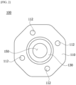
- the plate has a polygonal structure.
- the polygonal structure of the plate may be provided in a polygonal shape having a multiple of the number of the projection parts.
- An outermost point of the plate may be located under the projection part.
- Linear gear teeth may be formed on a through surface forming the through hole.
- a spiral screw thread may be formed on the through surface forming the through hole.
- the outer support part includes a cylindrical outer wall, and the projection part protrudes in an inward direction from the outer wall.
- the projection part and the neighboring projection parts may be disposed at the same interval on the outer support part.
- An upper surface of the projection part may have an inclined portion which is inclined downward from the projection part.
- a side surface of the projection part may be formed of an involute curve.
- the inner insertion part may be manufactured using a forging method and the outer support part may be manufactured using an injection method.
- a motor assembly including: a rotary shaft; a rotor including a hole in which the rotary shaft is disposed; a stator disposed at an outer side of the rotor; a housing configured to accommodate the rotor and the stator; and a coupler coupled to the rotary shaft, wherein the coupler includes an inner insertion part including a through hole and an outer support part configured to surround the outside of the inner insertion part.
- the inner insertion part includes a connection groove through which the outer support part passes, the outer support part includes at least one projection part configured to protrude in a center direction of the through hole, and the projection part includes a groove part.
- both a forging method and an injection method can be used to implement a detailed shape and increase a coupling force.
- an additional coupling structure can be added to an inner diameter of a coupler to ensure reliability of the coupling force.
- a structure of a coupling surface can be implemented as an involute shape to reduce a noise which occurs when a rotating direction is changed.
- the terms “on” or “under” include both a case in which the two elements are in direct contact with each other and a case in which at least one other element is indirectly disposed between the two elements to be formed. Further, when the terms “on” or “under” is expressed, a meaning of an upward direction and a downward direction with respect to one element may also be included.
- FIGS. 1 to 8 clearly illustrate only main characteristic parts to conceptually and clearly understand the present invention, and accordingly, an explanatory diagram may be variously modified, and the scope of the present invention does not have to be limited according to particular shapes shown in the drawings.
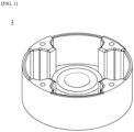
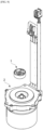
- FIG. 1 is a perspective view of a coupler according to an embodiment of the present invention
- FIG. 2 is a view illustrating a configuration of an inner insertion part which is an element of the present invention
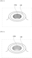
- FIG. 3 is a projection view illustrating a state in which the inner insertion part is inserted into an outer support part
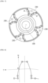
- FIG. 4 is a cross-sectional view of the coupler.
- the protruding part 130 is provided to protrude from one area in a center of the plate 110, and a through hole 150 connected to the shaft (not shown) is formed in the protruding part 130.
- the protruding part 130 shares a center with the plate 110 having the polygonal structure and may be provided in a pipe shape in which the through hole 150 is formed.
- the outer support part 200 includes an accommodation part 210, an outer wall 220, and a projection part 230.
- the outer support part 200 is connected to surround the outside of the inner insertion part 100.
- One area of the inner insertion part 100 is inserted into the accommodation part 210, and the accommodation part 210 may form a lower surface of the outer support part 200.
- the plate 110 of the inner insertion part 100 may be inserted into the accommodation part 210.
- an outer protruding part 240 into which the plate 110 is inserted and which is configured to come into contact with an outer surface of the protruding part 130, may be connected to the accommodation part 210.
- an area in which the outer protruding part 240 comes into contact with the protruding part 130 is not limited.
- the outer wall 220 is formed to be connected to an end portion of the accommodation part 210 and to protrude to one side.
- the outer wall 220 may form an inner space accommodating one end portion when coupled to the other object and may support the projection parts 230.
- a shape of the outer wall 220 may be transformed according to a shape of the coupled other object and is not limited to the shape in the drawing.
- At least one projection part 230 configured to protrude in an inward direction from the outer wall 220 is disposed on the outer wall 220.
- the plurality of projection parts 230 is provided to stably support coupling with the other object and be located to be spaced apart from each other at the predetermined interval with the neighboring projection part 230 to stably support the load and torque.
- At least one groove part 234 may be formed in the projection part 230.
- the projection part 230 may have a drying problem due to a thickness thereof.
- the groove part 234 may be formed in one area of the projection part 230.
- the groove part 234 may be formed in a downward direction from the upper portion of the projection part 230 and located in a center portion of the projection part 230.
- An inclined portion 232 inclined downward from the projection part 230 may be formed on an upper surface of the projection part 230.
- the inclined portion 232 may facilitate the engagement of the projection part 230 with the other object.
- the inner insertion part 100 coupled to the shaft is formed of a metal material and manufactured through a forging method to prevent damage due to a rigidity difference in the case in which a different material is used in coupling to the shaft.
- the projection part 230 may have a side surface provided in the shape of a curved surface and may be coupled to the other object to be inserted thereinto.
- a side surface of the projection part 230 may be formed in an involute shape.
- a curve provided by an involute curve may be bonded to the other object point-to-point.
- a conventional coupler has a structure which comes into contact with the other object surface-to-surface. In this case, a rotating direction of a motor is changed and noises are generated from a coupler surface of the other object and a coupler surface of the motor. However, since the projection part 230 provided with the involute curve comes into point contact with the other object, occurrence of noises during a change of the direction of the motor may be reduced.
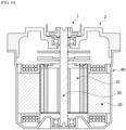
- FIG. 9 is an exploded perspective view of a motor assembly including a coupler according to another embodiment of the present invention
- FIG. 10 is a cross-sectional view of the motor assembly to which the coupler is coupled.
- reference numerals the same as those in FIGS. 1 to 8 show the same members and detailed descriptions thereof will be omitted.
- a motor assembly 2 may include a rotary shaft 30, a rotor 10 including a hole in which the rotary shaft 30 is disposed, a stator 20 disposed at an outer side of the rotor 10, a housing 40 configured to accommodate the rotor 10 and the stator 20, and a coupler 1 coupled to the rotary shaft 30.
- the rotor 10 is disposed in the stator 20.
- the rotor 10 may include a rotor core and a magnet coupled to the rotor core.
- the rotor 10 may be classified into the following types according to a coupling method between the rotor core and the magnet.
- the rotor 10 may be implemented as a type in which the magnet is coupled to an outer circumferential surface of the rotor core.
- a separate can member may be coupled to the rotor core to prevent separation of the magnet and increase a coupling force.
- the magnet and the rotor core may be integrally formed by double injection.
- the rotor 10 may be implemented as a type in which the magnet is coupled to the inside of the rotor core.
- a pocket into which the magnet is inserted into the rotor core may be provided.
- the rotor core of the rotor 10 may be formed by laminating a plurality of sheet-shaped plates.
- the rotor 10 may be formed in a shape in which a plurality of pucks forming a skew angle are stacked.
- the stator 20 causes electric interaction with the rotor 10 to induce rotation of the rotor 10.
- a coil may be wound around the stator 20 to cause the interaction between the stator 20 and the rotor 10.
- a specific configuration of the stator 20 on which the coil is wound will be described below.
Landscapes
- Engineering & Computer Science (AREA)
- General Engineering & Computer Science (AREA)
- Mechanical Engineering (AREA)
- Power Engineering (AREA)
- Iron Core Of Rotating Electric Machines (AREA)
- Connection Of Motors, Electrical Generators, Mechanical Devices, And The Like (AREA)
- Motor Or Generator Frames (AREA)
Claims (10)
- Coupleur comprenant :une partie d'insertion interne (100) ; etune partie de support externe (200) configurée pour entourer l'extérieur de la partie d'insertion interne, la partie de support externe (200) incluant une paroi externe cylindrique (220) et une pluralité de parties saillantes (230),caractérisé en ce que :la partie d'insertion interne (100) inclut une partie saillante cylindrique (130) présentant un trou traversant (150) disposé au centre de celle-ci et une plaque polygonale (110) configurée pour s'étendre dans une direction radiale à partir d'une surface circonférentielle extérieure de la partie saillante,la partie de support externe (200) inclut une partie de logement (210) couplée à la plaque (110), la paroi externe cylindrique étant configurée pour s'étendre à partir d'un bord de la partie de logement, et la pluralité de parties saillantes (230) étant configurées pour s'étendre vers la partie saillante (130) à partir d'un côté intérieur de la paroi externe (220),la plaque (110) inclut une pluralité de rainures de liaison (112), etla partie de logement (210) est partiellement disposée dans la rainure de liaison (112).
- Coupleur selon la revendication 1, dans lequel la structure polygonale de la plaque (110) est fournie sous forme polygonale présentant un multiple du nombre des parties saillantes (230).
- Coupleur selon la revendication 2, dans lequel un point le plus extérieur de la plaque (110) est situé sous la partie saillante (230).
- Coupleur selon la revendication 1,dans lequel la partie saillante (130) inclut une surface traversante (131) formant le trou traversant (150) ; etdans lequel une denture linéaire (132a) est formée sur la surface traversante.
- Coupleur selon la revendication 1,dans lequel la partie saillante (130) inclut une surface traversante (131) formant le trou traversant (150) ; etdans lequel un filetage en spirale (132b) est formé sur une surface traversante.
- Coupleur selon la revendication 1, dans lequel les parties saillantes (230) sont disposées à un même intervalle sur la partie de support externe.
- Coupleur selon la revendication 1, dans lequel une surface supérieure de la partie saillante (230) présente une portion inclinée (232) qui est inclinée vers le bas à partir de la partie saillante.
- Coupleur selon la revendication 7, dans lequel une surface latérale de la partie saillante (230) décrit une courbe involutive.
- Coupleur selon la revendication 1, dans lequel :la partie d'insertion interne (100) est fabriquée au moyen d'un procédé de forgeage ; etla partie de support externe (200) est fabriquée au moyen d'un procédé d'injection.
- Ensemble moteur comprenant :un arbre rotatif (30) ;un rotor (10) incluant un orifice dans lequel est disposé l'arbre rotatif ;un stator (20) disposé sur un côté extérieur du rotor ;un boîtier (40) configuré pour loger le rotor et le stator ; etun coupleur (1) selon la revendication 1, couplé à l'arbre rotatif.
Applications Claiming Priority (2)
| Application Number | Priority Date | Filing Date | Title |
|---|---|---|---|
| KR1020160163441A KR102626018B1 (ko) | 2016-12-02 | 2016-12-02 | 커플러 및 이를 포함하는 모터조립체 |
| PCT/KR2017/012711 WO2018101642A1 (fr) | 2016-12-02 | 2017-11-10 | Coupleur et ensemble moteur comportant ledit coupleur |
Publications (3)
| Publication Number | Publication Date |
|---|---|
| EP3550164A1 EP3550164A1 (fr) | 2019-10-09 |
| EP3550164A4 EP3550164A4 (fr) | 2020-07-08 |
| EP3550164B1 true EP3550164B1 (fr) | 2025-07-02 |
Family
ID=62241791
Family Applications (1)
| Application Number | Title | Priority Date | Filing Date |
|---|---|---|---|
| EP17875860.3A Active EP3550164B1 (fr) | 2016-12-02 | 2017-11-10 | Coupleur et ensemble moteur comportant ledit coupleur |
Country Status (6)
| Country | Link |
|---|---|
| US (1) | US11680606B2 (fr) |
| EP (1) | EP3550164B1 (fr) |
| JP (1) | JP6953528B2 (fr) |
| KR (1) | KR102626018B1 (fr) |
| CN (1) | CN110023641B (fr) |
| WO (1) | WO2018101642A1 (fr) |
Families Citing this family (4)
| Publication number | Priority date | Publication date | Assignee | Title |
|---|---|---|---|---|
| KR102626018B1 (ko) * | 2016-12-02 | 2024-01-18 | 엘지이노텍 주식회사 | 커플러 및 이를 포함하는 모터조립체 |
| USD958747S1 (en) * | 2020-05-21 | 2022-07-26 | Shanghai Microport Medbot (Group) Co., Ltd. | Coupler |
| USD959379S1 (en) | 2020-05-21 | 2022-08-02 | Shanghai Microport Medbot (Group) Co., Ltd. | Coupler |
| USD959378S1 (en) * | 2020-05-21 | 2022-08-02 | Shanghai Microport Medbot (Group) Co., Ltd. | Coupler |
Family Cites Families (20)
| Publication number | Priority date | Publication date | Assignee | Title |
|---|---|---|---|---|
| US2891395A (en) * | 1957-11-20 | 1959-06-23 | Robert R Chater | Flexible coupling |
| DE1450191B2 (de) | 1964-01-24 | 1970-07-16 | Societa Applicazioni Gomma Antivibranti Saga S.P.A., Mailand (Italien) | Verfahren zur Herstellung einer elastischen Wellenkupplung |
| US4914331A (en) * | 1988-08-02 | 1990-04-03 | Emerson Electric Co. | Minimum height motor assembly using aluminum endshields |
| JP4106838B2 (ja) | 1999-12-22 | 2008-06-25 | 株式会社デンソー | 動力伝達装置の組み付け方法 |
| JP2001231236A (ja) * | 2000-02-18 | 2001-08-24 | Matsushita Electric Ind Co Ltd | 円筒コアレスモータ |
| EP1487623A1 (fr) * | 2002-01-25 | 2004-12-22 | Highflyer Investments 5 (Proprietary) Limited | Cadre de roue de vehicule a moteur |
| JP4544398B2 (ja) * | 2004-02-06 | 2010-09-15 | トヨタ自動車株式会社 | 射出成形型 |
| JP2005308199A (ja) * | 2004-04-23 | 2005-11-04 | Sigma Kk | 回転体用ブッシュ |
| WO2008027032A1 (fr) * | 2006-08-29 | 2008-03-06 | Tritex Corporation | Couplage de diaphragme à un degré de liberté |
| KR20090005565A (ko) * | 2007-07-09 | 2009-01-14 | 주식회사 드림텍 | 무절삭 금속 인서트형 부시, 무절삭 금속 인서트형 부시의제조장치 및 방법 |
| US8344568B2 (en) * | 2010-08-17 | 2013-01-01 | Nidec Motor Corporation | Direct drive rotor with metal coupler |
| US9257885B2 (en) * | 2011-03-25 | 2016-02-09 | Mitsubishi Electric Corporation | Motor |
| KR101247135B1 (ko) | 2011-03-28 | 2013-04-01 | 김윤곤 | 경량형 커플링 |
| DE102012109887A1 (de) | 2011-10-20 | 2013-05-08 | Johnson Electric S.A. | Kupplung |
| JP2013139851A (ja) * | 2012-01-05 | 2013-07-18 | Ricoh Co Ltd | カップリング構造、プロセスカートリッジ、画像形成装置 |
| KR101951374B1 (ko) * | 2012-07-30 | 2019-02-22 | 엘지이노텍 주식회사 | 모터 |
| CN202789665U (zh) * | 2012-07-31 | 2013-03-13 | 中山大洋电机制造有限公司 | 一种风机风轮与电机转轴连接结构 |
| JP6277895B2 (ja) | 2014-07-15 | 2018-02-14 | 日本精工株式会社 | トルク伝達部材及び駆動軸と被駆動軸との結合部 |
| KR102355645B1 (ko) * | 2015-05-28 | 2022-01-26 | 엘지이노텍 주식회사 | 모터 |
| KR102626018B1 (ko) * | 2016-12-02 | 2024-01-18 | 엘지이노텍 주식회사 | 커플러 및 이를 포함하는 모터조립체 |
-
2016
- 2016-12-02 KR KR1020160163441A patent/KR102626018B1/ko active Active
-
2017
- 2017-11-10 WO PCT/KR2017/012711 patent/WO2018101642A1/fr not_active Ceased
- 2017-11-10 JP JP2019525821A patent/JP6953528B2/ja active Active
- 2017-11-10 EP EP17875860.3A patent/EP3550164B1/fr active Active
- 2017-11-10 CN CN201780074232.3A patent/CN110023641B/zh active Active
- 2017-11-10 US US16/462,133 patent/US11680606B2/en active Active
Also Published As
| Publication number | Publication date |
|---|---|
| US20190331168A1 (en) | 2019-10-31 |
| JP6953528B2 (ja) | 2021-10-27 |
| KR102626018B1 (ko) | 2024-01-18 |
| EP3550164A1 (fr) | 2019-10-09 |
| CN110023641A (zh) | 2019-07-16 |
| EP3550164A4 (fr) | 2020-07-08 |
| KR20180063560A (ko) | 2018-06-12 |
| WO2018101642A1 (fr) | 2018-06-07 |
| CN110023641B (zh) | 2022-08-12 |
| JP2019536955A (ja) | 2019-12-19 |
| US11680606B2 (en) | 2023-06-20 |
Similar Documents
| Publication | Publication Date | Title |
|---|---|---|
| EP3550164B1 (fr) | Coupleur et ensemble moteur comportant ledit coupleur | |
| JP6982612B2 (ja) | ステーターおよびこれを含むモーター | |
| US8928200B2 (en) | Rotating electric machine | |
| EP2439832A2 (fr) | Stator à noyau divisé de moteur de direction assistée électrique | |
| US9371901B2 (en) | Pulley structure of belt type electric power steering gear | |
| EP2439835B1 (fr) | Structure anti-séparation d'aimant de détection pour moteur EPS | |
| US9347534B2 (en) | Ball screw device and electric power steering system including the same | |
| EP3748820B1 (fr) | Rotor pour machine dynamoélectrique et machine dynamoélectrique | |
| JP5962027B2 (ja) | 回転電機 | |
| EP2456046B1 (fr) | Stator et moteur comprenant ce stator | |
| JP5864839B2 (ja) | 電動パワーステアリング装置用左右回転型ブラシレスモータの製造方法 | |
| CN217048754U (zh) | 用于车辆的转向反作用力产生装置 | |
| JP2005045923A (ja) | 電動機回転子の製造方法及び電動機回転子 | |
| JP5973141B2 (ja) | ブラシレスモータと、これを利用する電動パワーステアリング装置 | |
| EP2551996A2 (fr) | Moteur de direction assistée | |
| JP2022121192A (ja) | 回転電機 | |
| JP2016026468A (ja) | 電動パワーステアリング装置用ブラシレスモータ製造方法 | |
| US12103606B2 (en) | Worm wheel of steering system speed reducer, and manufacturing method therefor | |
| KR102757913B1 (ko) | 모터 | |
| KR20210088270A (ko) | 모터 | |
| US12368336B2 (en) | Rotary electric machine | |
| JP6173407B2 (ja) | 電動パワーステアリング装置用ブラシレスモータ製造方法 |
Legal Events
| Date | Code | Title | Description |
|---|---|---|---|
| STAA | Information on the status of an ep patent application or granted ep patent |
Free format text: STATUS: THE INTERNATIONAL PUBLICATION HAS BEEN MADE |
|
| PUAI | Public reference made under article 153(3) epc to a published international application that has entered the european phase |
Free format text: ORIGINAL CODE: 0009012 |
|
| STAA | Information on the status of an ep patent application or granted ep patent |
Free format text: STATUS: REQUEST FOR EXAMINATION WAS MADE |
|
| 17P | Request for examination filed |
Effective date: 20190528 |
|
| AK | Designated contracting states |
Kind code of ref document: A1 Designated state(s): AL AT BE BG CH CY CZ DE DK EE ES FI FR GB GR HR HU IE IS IT LI LT LU LV MC MK MT NL NO PL PT RO RS SE SI SK SM TR |
|
| AX | Request for extension of the european patent |
Extension state: BA ME |
|
| DAV | Request for validation of the european patent (deleted) | ||
| DAX | Request for extension of the european patent (deleted) | ||
| A4 | Supplementary search report drawn up and despatched |
Effective date: 20200609 |
|
| RIC1 | Information provided on ipc code assigned before grant |
Ipc: B29L 31/00 20060101ALI20200604BHEP Ipc: F16D 3/68 20060101ALI20200604BHEP Ipc: B29L 31/30 20060101ALI20200604BHEP Ipc: B21K 1/14 20060101ALI20200604BHEP Ipc: H02K 7/116 20060101AFI20200604BHEP |
|
| STAA | Information on the status of an ep patent application or granted ep patent |
Free format text: STATUS: EXAMINATION IS IN PROGRESS |
|
| 17Q | First examination report despatched |
Effective date: 20221108 |
|
| GRAP | Despatch of communication of intention to grant a patent |
Free format text: ORIGINAL CODE: EPIDOSNIGR1 |
|
| STAA | Information on the status of an ep patent application or granted ep patent |
Free format text: STATUS: GRANT OF PATENT IS INTENDED |
|
| INTG | Intention to grant announced |
Effective date: 20250402 |
|
| GRAS | Grant fee paid |
Free format text: ORIGINAL CODE: EPIDOSNIGR3 |
|
| GRAA | (expected) grant |
Free format text: ORIGINAL CODE: 0009210 |
|
| STAA | Information on the status of an ep patent application or granted ep patent |
Free format text: STATUS: THE PATENT HAS BEEN GRANTED |
|
| AK | Designated contracting states |
Kind code of ref document: B1 Designated state(s): AL AT BE BG CH CY CZ DE DK EE ES FI FR GB GR HR HU IE IS IT LI LT LU LV MC MK MT NL NO PL PT RO RS SE SI SK SM TR |
|
| RAP3 | Party data changed (applicant data changed or rights of an application transferred) |
Owner name: LG INNOTEK CO., LTD. |
|
| REG | Reference to a national code |
Ref country code: GB Ref legal event code: FG4D |
|
| REG | Reference to a national code |
Ref country code: CH Ref legal event code: EP |
|
| REG | Reference to a national code |
Ref country code: DE Ref legal event code: R096 Ref document number: 602017090353 Country of ref document: DE |
|
| REG | Reference to a national code |
Ref country code: IE Ref legal event code: FG4D |
|
| REG | Reference to a national code |
Ref country code: NL Ref legal event code: FP |
|
| PGFP | Annual fee paid to national office [announced via postgrant information from national office to epo] |
Ref country code: NL Payment date: 20251020 Year of fee payment: 9 |
|
| PG25 | Lapsed in a contracting state [announced via postgrant information from national office to epo] |
Ref country code: PT Free format text: LAPSE BECAUSE OF FAILURE TO SUBMIT A TRANSLATION OF THE DESCRIPTION OR TO PAY THE FEE WITHIN THE PRESCRIBED TIME-LIMIT Effective date: 20251103 |
|
| REG | Reference to a national code |
Ref country code: AT Ref legal event code: MK05 Ref document number: 1810419 Country of ref document: AT Kind code of ref document: T Effective date: 20250702 |
|
| PG25 | Lapsed in a contracting state [announced via postgrant information from national office to epo] |
Ref country code: IS Free format text: LAPSE BECAUSE OF FAILURE TO SUBMIT A TRANSLATION OF THE DESCRIPTION OR TO PAY THE FEE WITHIN THE PRESCRIBED TIME-LIMIT Effective date: 20251102 |
|
| PGFP | Annual fee paid to national office [announced via postgrant information from national office to epo] |
Ref country code: DE Payment date: 20251020 Year of fee payment: 9 |
|
| PG25 | Lapsed in a contracting state [announced via postgrant information from national office to epo] |
Ref country code: NO Free format text: LAPSE BECAUSE OF FAILURE TO SUBMIT A TRANSLATION OF THE DESCRIPTION OR TO PAY THE FEE WITHIN THE PRESCRIBED TIME-LIMIT Effective date: 20251002 |
|
| REG | Reference to a national code |
Ref country code: LT Ref legal event code: MG9D |
|
| PG25 | Lapsed in a contracting state [announced via postgrant information from national office to epo] |
Ref country code: AT Free format text: LAPSE BECAUSE OF FAILURE TO SUBMIT A TRANSLATION OF THE DESCRIPTION OR TO PAY THE FEE WITHIN THE PRESCRIBED TIME-LIMIT Effective date: 20250702 |
|
| PG25 | Lapsed in a contracting state [announced via postgrant information from national office to epo] |
Ref country code: FI Free format text: LAPSE BECAUSE OF FAILURE TO SUBMIT A TRANSLATION OF THE DESCRIPTION OR TO PAY THE FEE WITHIN THE PRESCRIBED TIME-LIMIT Effective date: 20250702 |
|
| PG25 | Lapsed in a contracting state [announced via postgrant information from national office to epo] |
Ref country code: HR Free format text: LAPSE BECAUSE OF FAILURE TO SUBMIT A TRANSLATION OF THE DESCRIPTION OR TO PAY THE FEE WITHIN THE PRESCRIBED TIME-LIMIT Effective date: 20250702 |
|
| PG25 | Lapsed in a contracting state [announced via postgrant information from national office to epo] |
Ref country code: GR Free format text: LAPSE BECAUSE OF FAILURE TO SUBMIT A TRANSLATION OF THE DESCRIPTION OR TO PAY THE FEE WITHIN THE PRESCRIBED TIME-LIMIT Effective date: 20251003 |
|
| PG25 | Lapsed in a contracting state [announced via postgrant information from national office to epo] |
Ref country code: SE Free format text: LAPSE BECAUSE OF FAILURE TO SUBMIT A TRANSLATION OF THE DESCRIPTION OR TO PAY THE FEE WITHIN THE PRESCRIBED TIME-LIMIT Effective date: 20250702 Ref country code: CZ Free format text: LAPSE BECAUSE OF FAILURE TO SUBMIT A TRANSLATION OF THE DESCRIPTION OR TO PAY THE FEE WITHIN THE PRESCRIBED TIME-LIMIT Effective date: 20250702 |
|
| PG25 | Lapsed in a contracting state [announced via postgrant information from national office to epo] |
Ref country code: LV Free format text: LAPSE BECAUSE OF FAILURE TO SUBMIT A TRANSLATION OF THE DESCRIPTION OR TO PAY THE FEE WITHIN THE PRESCRIBED TIME-LIMIT Effective date: 20250702 |
|
| PG25 | Lapsed in a contracting state [announced via postgrant information from national office to epo] |
Ref country code: PL Free format text: LAPSE BECAUSE OF FAILURE TO SUBMIT A TRANSLATION OF THE DESCRIPTION OR TO PAY THE FEE WITHIN THE PRESCRIBED TIME-LIMIT Effective date: 20250702 Ref country code: BG Free format text: LAPSE BECAUSE OF FAILURE TO SUBMIT A TRANSLATION OF THE DESCRIPTION OR TO PAY THE FEE WITHIN THE PRESCRIBED TIME-LIMIT Effective date: 20250702 |
|
| PG25 | Lapsed in a contracting state [announced via postgrant information from national office to epo] |
Ref country code: RS Free format text: LAPSE BECAUSE OF FAILURE TO SUBMIT A TRANSLATION OF THE DESCRIPTION OR TO PAY THE FEE WITHIN THE PRESCRIBED TIME-LIMIT Effective date: 20251002 |
|
| PG25 | Lapsed in a contracting state [announced via postgrant information from national office to epo] |
Ref country code: ES Free format text: LAPSE BECAUSE OF FAILURE TO SUBMIT A TRANSLATION OF THE DESCRIPTION OR TO PAY THE FEE WITHIN THE PRESCRIBED TIME-LIMIT Effective date: 20250702 |
|
| PG25 | Lapsed in a contracting state [announced via postgrant information from national office to epo] |
Ref country code: RO Free format text: LAPSE BECAUSE OF FAILURE TO SUBMIT A TRANSLATION OF THE DESCRIPTION OR TO PAY THE FEE WITHIN THE PRESCRIBED TIME-LIMIT Effective date: 20250702 |
|
| PG25 | Lapsed in a contracting state [announced via postgrant information from national office to epo] |
Ref country code: SM Free format text: LAPSE BECAUSE OF FAILURE TO SUBMIT A TRANSLATION OF THE DESCRIPTION OR TO PAY THE FEE WITHIN THE PRESCRIBED TIME-LIMIT Effective date: 20250702 |
|
| PG25 | Lapsed in a contracting state [announced via postgrant information from national office to epo] |
Ref country code: DK Free format text: LAPSE BECAUSE OF FAILURE TO SUBMIT A TRANSLATION OF THE DESCRIPTION OR TO PAY THE FEE WITHIN THE PRESCRIBED TIME-LIMIT Effective date: 20250702 |
|
| PG25 | Lapsed in a contracting state [announced via postgrant information from national office to epo] |
Ref country code: IT Free format text: LAPSE BECAUSE OF FAILURE TO SUBMIT A TRANSLATION OF THE DESCRIPTION OR TO PAY THE FEE WITHIN THE PRESCRIBED TIME-LIMIT Effective date: 20250702 |
|
| PG25 | Lapsed in a contracting state [announced via postgrant information from national office to epo] |
Ref country code: EE Free format text: LAPSE BECAUSE OF FAILURE TO SUBMIT A TRANSLATION OF THE DESCRIPTION OR TO PAY THE FEE WITHIN THE PRESCRIBED TIME-LIMIT Effective date: 20250702 Ref country code: SK Free format text: LAPSE BECAUSE OF FAILURE TO SUBMIT A TRANSLATION OF THE DESCRIPTION OR TO PAY THE FEE WITHIN THE PRESCRIBED TIME-LIMIT Effective date: 20250702 |