EP3550102A2 - Assembly of a building door with a sealing unit and a locking device - Google Patents
Assembly of a building door with a sealing unit and a locking device Download PDFInfo
- Publication number
- EP3550102A2 EP3550102A2 EP19163547.3A EP19163547A EP3550102A2 EP 3550102 A2 EP3550102 A2 EP 3550102A2 EP 19163547 A EP19163547 A EP 19163547A EP 3550102 A2 EP3550102 A2 EP 3550102A2
- Authority
- EP
- European Patent Office
- Prior art keywords
- seal assembly
- sealing unit
- assembly
- locking
- locking device
- Prior art date
- Legal status (The legal status is an assumption and is not a legal conclusion. Google has not performed a legal analysis and makes no representation as to the accuracy of the status listed.)
- Granted
Links
Images


Classifications
-
- E—FIXED CONSTRUCTIONS
- E06—DOORS, WINDOWS, SHUTTERS, OR ROLLER BLINDS IN GENERAL; LADDERS
- E06B—FIXED OR MOVABLE CLOSURES FOR OPENINGS IN BUILDINGS, VEHICLES, FENCES OR LIKE ENCLOSURES IN GENERAL, e.g. DOORS, WINDOWS, BLINDS, GATES
- E06B7/00—Special arrangements or measures in connection with doors or windows
- E06B7/16—Sealing arrangements on wings or parts co-operating with the wings
- E06B7/18—Sealing arrangements on wings or parts co-operating with the wings by means of movable edgings, e.g. draught sealings additionally used for bolting, e.g. by spring force or with operating lever
- E06B7/20—Sealing arrangements on wings or parts co-operating with the wings by means of movable edgings, e.g. draught sealings additionally used for bolting, e.g. by spring force or with operating lever automatically withdrawn when the wing is opened, e.g. by means of magnetic attraction, a pin or an inclined surface, especially for sills
-
- E—FIXED CONSTRUCTIONS
- E05—LOCKS; KEYS; WINDOW OR DOOR FITTINGS; SAFES
- E05B—LOCKS; ACCESSORIES THEREFOR; HANDCUFFS
- E05B47/00—Operating or controlling locks or other fastening devices by electric or magnetic means
- E05B47/0001—Operating or controlling locks or other fastening devices by electric or magnetic means with electric actuators; Constructional features thereof
- E05B47/0012—Operating or controlling locks or other fastening devices by electric or magnetic means with electric actuators; Constructional features thereof with rotary electromotors
-
- E—FIXED CONSTRUCTIONS
- E05—LOCKS; KEYS; WINDOW OR DOOR FITTINGS; SAFES
- E05C—BOLTS OR FASTENING DEVICES FOR WINGS, SPECIALLY FOR DOORS OR WINDOWS
- E05C9/00—Arrangements of simultaneously actuated bolts or other securing devices at well-separated positions on the same wing
- E05C9/06—Arrangements of simultaneously actuated bolts or other securing devices at well-separated positions on the same wing with three or more sliding bars
- E05C9/063—Arrangements of simultaneously actuated bolts or other securing devices at well-separated positions on the same wing with three or more sliding bars extending along three or more sides of the wing or frame
-
- E—FIXED CONSTRUCTIONS
- E05—LOCKS; KEYS; WINDOW OR DOOR FITTINGS; SAFES
- E05C—BOLTS OR FASTENING DEVICES FOR WINGS, SPECIALLY FOR DOORS OR WINDOWS
- E05C9/00—Arrangements of simultaneously actuated bolts or other securing devices at well-separated positions on the same wing
- E05C9/18—Details of fastening means or of fixed retaining means for the ends of bars
-
- E—FIXED CONSTRUCTIONS
- E06—DOORS, WINDOWS, SHUTTERS, OR ROLLER BLINDS IN GENERAL; LADDERS
- E06B—FIXED OR MOVABLE CLOSURES FOR OPENINGS IN BUILDINGS, VEHICLES, FENCES OR LIKE ENCLOSURES IN GENERAL, e.g. DOORS, WINDOWS, BLINDS, GATES
- E06B7/00—Special arrangements or measures in connection with doors or windows
- E06B7/16—Sealing arrangements on wings or parts co-operating with the wings
- E06B7/18—Sealing arrangements on wings or parts co-operating with the wings by means of movable edgings, e.g. draught sealings additionally used for bolting, e.g. by spring force or with operating lever
- E06B7/20—Sealing arrangements on wings or parts co-operating with the wings by means of movable edgings, e.g. draught sealings additionally used for bolting, e.g. by spring force or with operating lever automatically withdrawn when the wing is opened, e.g. by means of magnetic attraction, a pin or an inclined surface, especially for sills
- E06B7/21—Sealing arrangements on wings or parts co-operating with the wings by means of movable edgings, e.g. draught sealings additionally used for bolting, e.g. by spring force or with operating lever automatically withdrawn when the wing is opened, e.g. by means of magnetic attraction, a pin or an inclined surface, especially for sills with sealing strip movable in plane of wing
-
- E—FIXED CONSTRUCTIONS
- E06—DOORS, WINDOWS, SHUTTERS, OR ROLLER BLINDS IN GENERAL; LADDERS
- E06B—FIXED OR MOVABLE CLOSURES FOR OPENINGS IN BUILDINGS, VEHICLES, FENCES OR LIKE ENCLOSURES IN GENERAL, e.g. DOORS, WINDOWS, BLINDS, GATES
- E06B7/00—Special arrangements or measures in connection with doors or windows
- E06B7/16—Sealing arrangements on wings or parts co-operating with the wings
- E06B7/18—Sealing arrangements on wings or parts co-operating with the wings by means of movable edgings, e.g. draught sealings additionally used for bolting, e.g. by spring force or with operating lever
- E06B7/20—Sealing arrangements on wings or parts co-operating with the wings by means of movable edgings, e.g. draught sealings additionally used for bolting, e.g. by spring force or with operating lever automatically withdrawn when the wing is opened, e.g. by means of magnetic attraction, a pin or an inclined surface, especially for sills
- E06B7/215—Sealing arrangements on wings or parts co-operating with the wings by means of movable edgings, e.g. draught sealings additionally used for bolting, e.g. by spring force or with operating lever automatically withdrawn when the wing is opened, e.g. by means of magnetic attraction, a pin or an inclined surface, especially for sills with sealing strip being moved to a retracted position by elastic means, e.g. springs
Definitions
- the invention relates to an assembly of a building door according to the preamble of claim 1.
- Such an assembly comprises a sealing unit to be arranged on a door leaf, comprising a housing and a seal assembly movable between a first, retracted position and a second, extended position along an adjustment direction to the housing for at least partially sealing the door leaf in a closed position relative to a floor and / or has a door frame.
- On the door wing is also to arrange an adjustable between an unlocking position and a locking position locking device, which serves to lock the door leaf in the closed position.
- a door In conventional building doors, for example, interior doors or exterior doors to a building, a door is pivotally mounted, for example, on a door frame. There is usually a gap between the door leaf and a floor of the building, which is required in order to allow a simple, unhindered movement of the door leaf relative to the door frame.
- this can also be, for example, a patio door and, in this regard, a swing door or even a sliding door.
- the door leaf in its closed position may be at least largely sealed off from the door frame and the floor in order to prevent draft and sound transmission through the building door.
- This purpose is served by the sealing unit arranged on the door leaf, the sealing assembly of which is adjustable in particular when the door leaf is closed so that the door leaf is sealed off from the door frame and / or the floor. For example, if the sealing unit serves as a bottom seal, then the seal assembly can be lowered with the door closed, thus closing a gap between the door leaf and the floor and thus suppressing draft and sound transmission across the gap.
- a sealing unit of this type should be easy to assemble, but also allow an effective seal with the door closed.
- the seal assembly must be adjustable so that unimpeded opening and closing of the door leaf without loosening the seal assembly on the floor or on the door frame is possible.
- a sealing profile via an adjusting mechanism on a door is movable.
- a closed state of the door can be detected in order to move the sealing profile depending on the closed state.
- At one of the DE 297 22 616 U1 known door assembly is an automatically lowerable bottom seal embedded in a door leaf.
- the DE 20 2013 100 864 U1 describes a bottom rail for window and door elements, which has a compensating element, which can be adjusted in its altitude relative to a support element for adjusting to the floor level.
- At one of the EP 1 772 586 B1 known bottom seal is a sealant mechanically mounted in a seal housing.
- Object of the present invention is to provide an assembly of a building door and a building door available that allow a simple way a reliable adjustment of a seal assembly of the sealing unit in response to the closed position of the door leaf.
- the assembly has a coupling device for coupling the locking device with the sealing unit such that upon an adjustment of the locking device from the unlocking position to the locking position, the seal assembly in the second, extended position and / or in an adjustment of the locking device from the locking position is moved to the unlocked position in the first, retracted position.
- the sealing unit and the locking device of a building door are coupled together.
- An adjustment movement of the locking device is thus transmitted to the sealing unit via the coupling device, which is preferably designed for the mechanical transmission of force, so that when the locking device is locked, the sealing unit transfers the sealing unit into the second retracted position in the second, extended position and / or when the locking device is unlocked becomes.
- the adjustment of the sealing unit thus takes place in dependence on an adjustment of the locking device, which makes it possible to design the sealing unit without its own drive.
- the present invention is based on the recognition that the actuation of the sealing unit and the actuation of the locking device in principle have to be done simultaneously.
- the locking device when closing the building door, the locking device should lock the door leaf, for example, with a door frame as soon as the closed position is reached.
- the seal assembly of the sealing unit In the closed position and the seal assembly of the sealing unit should be transferred to the second, extended position to seal the door, for example, against a floor and thus to close a gap between the door and the floor at least as far as possible.
- the adjustment of the locking device and the movement of the seal assembly in the second, extended position are thus each carried out after reaching the closed position, which makes it possible to perform the movement of the seal assembly in response to and controlled by the locking device.
- the locking device is coupled via the coupling device with the sealing unit, can be adjusting forces from the locking device to the sealing unit be transferred, which makes it possible to dispense with a separate drive for the sealing unit.
- the locking device may be formed in a simple configuration as to be arranged on the door leaf door lock.
- the door lock has, for example, a so-called latch, which snaps when closing the door into engagement with an associated locking recess on the door frame and can be adjusted electrically, for example by a door handle manually or by an electric motor drive means.
- the locking device is connected to the sealing unit, so that an actuation of the locking device also triggers a movement of the sealing assembly of the sealing unit.
- the locking device has an (electromotive) drive device, one or more latch assemblies with adjustable locking elements and a drive element driven by the transmission element for adjusting the locking elements of the latch assembly.
- the transmission element can be designed, for example, as a rod which can be adjusted on the door leaf and is preferably coupled to the sealing unit via the coupling device.
- the drive means serves to adjust the transmission element, wherein via the coupling means an adjusting force can also be transmitted to the sealing unit to move in this way the seal assembly between the first, retracted position and the second, extended position.
- the locking device may for example be designed as a so-called multiple locking with multiple latch assemblies, each with an adjustable locking element.
- the bolt assemblies can be adjusted synchronously by adjusting the transmission element, the sealing unit also being actuated via the coupling device coupled to the transmission element and the sealing assembly of the sealing unit thus adjusted as a function of the position of the locking device.
- Such a multi-point lock can be used, for example, in the case of a building door in the form of a front door.
- the locking device can, alternatively, but also for example by a so-called turn-tilt fitting be realized by means of which a door or a window, for example a patio door, between a locked position, a pivotal position (in a pivoting of a wing to a vertical swivel axis is possible) and a tilted position (in which a tilting of the wing about a horizontal tilting axis is possible) can be brought.
- a so-called turn-tilt fitting be realized by means of which a door or a window, for example a patio door, between a locked position, a pivotal position (in a pivoting of a wing to a vertical swivel axis is possible) and a tilted position (in which a tilting of the wing about a horizontal tilting axis is possible) can be brought.
- the coupling device may be formed, for example, as a Bowden cable.
- a Bowden sheath for example, supported on the door, while a guided in the Bowden soul of the Bowden cable is connected on the one hand with the transmission element of the locking device and on the other hand with the sealing unit, so by adjusting the soul of the Bowden cable relative to the Bowden sheath Verstell concept of the transmission element of Locking device can be transferred to the sealing unit.
- the coupling device can also be designed as a so-called corner drive, with a guided in a coupling guide flexible power transmission element.
- a corner drive forces can be deflected in a horizontal direction of movement along the lower edge of the door leaf from a vertical direction of movement, along which the transmission element in the form of the rod of the locking device to move along the closing edge of the door.
- the power transmission element may be formed, for example, as a flexible strip, for example made of spring steel, which is adjustable along the coupling guide, wherein the coupling guide extends along a curved path and thus forces are deflected via the force transmission element.
- the coupling device is designed as a driver for coupling the locking device with the sealing unit.
- the driver is configured such that, for example, during a movement of a transmission element in the form of a linkage of the locking device, an adjusting force is introduced into the sealing unit for adjusting the seal assembly and insofar an adjusting mechanism of the sealing unit is taken.
- an adjusting mechanism of the sealing unit is completely integrated in the housing of the sealing unit.
- the coupling device for example in the form of a Bowden cable or a corner drive, for example, extends at a location into the housing of the sealing unit and is coupled within the housing with the adjusting mechanism of the sealing unit.
- the sealing unit has one or more spring elements for biasing the seal assembly relative to the housing in the direction of the first, retracted position or the second, extended position.
- the movement of the seal assembly in the direction of the first, retracted position or the second, extended position is thus supported spring-mechanically via one or more spring elements, so that the seal assembly, for example, in one direction via a transmitted via the coupling device in the form of the Bowden cable tensile force (contrary to Effect of the spring elements) and can be adjusted in the other direction by spring forces of the spring elements.
- An elasticity on the seal assembly can also be provided via one or more spring elements, which makes it possible, for example, to compensate for unevenness in the ground or tolerances in the adjustment system, so that the seal assembly can reliably rest on the ground, for example, when the door is closed. A complex readjustment of the seal assembly and the adjustment of the sealing unit is no longer required.
- the coupling device can-in one embodiment-also be coupled with an adjusting mechanism for adjusting the seal assembly between the retracted position and the extended position.
- the coupling device can be coupled via a first spring element (for example in the form of a helical spring designed as a tension spring) to a first end of a connecting element which is connected to an adjusting mechanism for adjusting the seal assembly (for example in the form of a lever mechanism).
- a second end of the connecting element can be spring-biased relative to the housing via a second spring element (for example in the form of a helical spring designed as a tension spring).
- a spring element can thus, in one embodiment, be arranged in the power transmission line between the coupling device and the adjusting mechanism of the sealing unit, so that forces can be introduced into the adjusting mechanism via the spring element.
- the spring element can, in one embodiment, be designed, for example, as a tension-to-tension helical spring.
- the spring element is designed for example as a leg spring with a first spring end in the form of a first leg and a second spring end in the form of a second leg.
- the first spring end can be fixed in place on the housing, for example via a fastening element, while the second spring end is connected to a push element which is adjustable relative to the housing (in particular transversely to the adjustment direction).
- the pusher is moved, for example, via the coupling means and adjustment forces introduced therefrom or via spring forces of the spring members.
- the coupling means may engage the pusher member to introduce adjustment forces from the latching means into the sealing unit and to adjust the seal assembly towards the first retracted position or towards the second extended position.
- the first spring end and the second spring end are preferably angled relative to each other and angularly adjustable relative to one another.
- the spring element (along the adjustment of the seal assembly) is supported to the housing, while in the middle between the spring ends, for example at the location of a spring winding, in one embodiment, a sliding element is arranged over which the spring element guided transversely to the adjustment sliding on the seal assembly is such that when moving the seal assembly, a transverse movement of the pusher can be compensated.
- the seal assembly may for this purpose have a suitable sliding guide on which the slider connected to the spring element is slidably guided.
- an adjusting movement of the locking device leads to a movement of the seal assembly both from the first, retracted position to the second, extended position and vice versa from the second, extended position to the first, retracted position.
- the seal assembly is extended out of the housing of the sealing unit, for example to seal a gap between the door leaf and a floor.
- the seal assembly is lifted and transferred to the first, retracted position in which the seal assembly is at least partially retracted into the housing of the sealing unit.
- a movement of the transmission element of Locking device is thus implemented (directly) in a movement of the sealing assembly of the sealing unit in this case.
- an adjusting movement of the locking device is implemented only in one direction in a movement of the seal assembly, for example, for transferring the seal assembly from the second, extended position to the first, retracted position when unlocking the locking device.
- the movement of the seal assembly is independent of the locking device, controlled, for example, depending on the door movement.
- the pusher may be connected to the housing, for example via a damping element, for example in the form of a gas spring or the like.
- a damping element for example in the form of a gas spring or the like.
- the sealing unit may have a blocking assembly with a blocking element and a triggering element.
- the seal assembly In the first, retracted position, the seal assembly is in this case blocked, for example via the blocking element with respect to the housing and is thus held in position to the housing. If the trigger element is actuated when the door leaf is closed, the blocking element is thereby unlocked, so that the seal assembly is moved from the first, retracted position to the second, extended position, driven, for example, by the spring forces of the (pretensioned) spring elements.
- the sealing assembly is thus latched in the first, retracted position via the blocking element, which is designed, for example, as a locking lever arranged on the housing, and is thus held in the first, retracted position via the blocking element.
- the triggering element triggers the blocking element and, in particular, releases the latching of the blocking element with the seal assembly, so that the seal assembly can automatically move from the first, retracted position in the direction of the second, extended position.
- the blocking element can, for example, interact with the thrust element guided adjustably on the housing of the sealing unit transversely to the adjustment direction in order to lock the thrust element and also the sealing assembly in the first, retracted position. If the latch is released by actuation of the trigger element, the pusher and thus also the seal assembly is released, so that the seal assembly can be transferred from the first, retracted position in the direction of the second, extended position.
- the triggering element can be operatively connected, for example, with a pressure element, which runs when closing the door leaf, for example, on a door frame and thereby actuates the triggering element. If the door leaf is closed, triggers the trigger element on reaching the closed position and unlocks the seal assembly, so that it is automatically moved in the direction of the second, extended position.
- a pressure element which runs when closing the door leaf, for example, on a door frame and thereby actuates the triggering element. If the door leaf is closed, triggers the trigger element on reaching the closed position and unlocks the seal assembly, so that it is automatically moved in the direction of the second, extended position.
- the assembly on an adjusting mechanism for adjusting the seal assembly which may be configured, for example, as a pinion gear.
- a rack is arranged on the seal assembly, which is in meshing engagement with a rotatably mounted to the housing pinion.
- the pinion can be driven to move in this way the rack and about the seal assembly to adjust along the adjustment.
- the pinion can be driven in this case for example via a drive linkage, which is in meshing engagement via a toothing with the pinion and can be moved along a direction of movement in order to enable the pinion to rotate in this manner.
- a drive linkage which is in meshing engagement via a toothing with the pinion and can be moved along a direction of movement in order to enable the pinion to rotate in this manner.
- the drive linkage can be coupled to the coupling device, for example, so that the sealing assembly can be moved in the direction of the extended position as well as in the retracted position by means of the adjusting mechanism.
- the seal assembly is automatically extended, and when unlocking the locking device, conversely, the seal assembly is retracted automatically.
- the drive linkage may be biased, for example via a mechanical spring, for example a compression spring, or a hydraulic or pneumatic spring in the form of a damping spring relative to the housing, so that after unlocking the locking element, the seal assembly is transferred due to the spring bias in the extended position.
- a reset of the seal assembly takes place in this case via the coupling device, for example via a driver over which the drive linkage is reset and the seal assembly is thus raised.
- the coupling device in which a movement of the seal assembly takes place both in the extended position and in the retracted position by force transmission via the coupling device, can be operatively connected, for example via a link element with the seal assembly. Via the link element, a force introduced via the coupling device is deflected on the principle of the inclined plane in such a way that the seal assembly is adjusted along the adjustment direction between the retracted position and the extended position.
- the link element which is arranged in one embodiment on the side of the seal assembly, has, for example, obliquely to the adjustment extended linkage, in which engages a coupling device associated engagement element, so that upon movement of the coupling device, the engagement element adjusted in the backdrop and thereby the Setting element is adjusted together with the seal assembly along the adjustment.
- An adjustment mechanism for adjusting the seal assembly can, in one embodiment, also be realized by a lever mechanism having, for example, a lever element and an articulated lever connected to the lever element.
- the adjusting lever may for example be mounted stationarily on the housing.
- the lever member is hingedly connected at one end to the seal assembly and with the other end, for example, arranged on a slide element which can be moved to pivot in this way, the lever member between a pivoted, the retracted position of the seal assembly associated position and a pivoted, the extended position of the seal assembly associated position.
- the seal assembly may be guided longitudinally along the displacement direction of the housing, so that the seal assembly (exclusively) along the direction of adjustment to the housing is movable.
- the coupling device can be decoupled from the sealing unit depending on the position of the seal assembly, so that the locking device is adjustable independently of the sealing unit.
- the coupling device is thus not permanently connected to the sealing unit, but detachable from the sealing unit. This makes it possible to adjust the locking device independently of the sealing unit, so that the locking device can be displaced, for example, between different unlocked positions (for example in the case of a turn-tilt fitting between an unlocked pivot position and an unlocked tilt position) while the sealing unit remains in position.
- the coupling device in the extended position of the sealing assembly, may be coupled to the sealing unit, for example a connecting element in the form of a linkage of the sealing unit.
- the locking device In this position of the seal assembly, the locking device may for example be in a locked position. If the locking device is actuated in the direction of an unlocked position, the seal assembly is thereby adjusted from the extended position to the retracted position, wherein, for example, tensile forces can be introduced into an adjustment mechanism of the sealing unit. If the seal assembly has reached its retracted position, then the coupling device can decouple from the sealing unit, so that a further adjustment of the locking device can be independent of the sealing unit. In this case, there is no longer an operative connection between the seal assembly and the coupling device.
- a building door may, for example, have a door frame and a door wing which is movable, in particular pivotable or displaceable, relative to the door frame.
- An assembly of the type described above serves on the one hand for locking the door leaf with the door frame in the closed position and also for sealing the door leaf relative to a floor and / or with respect to the door frame.
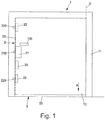
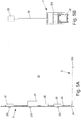
- Fig. 1 shows a schematic view of a building door 1, which has a pivotable about a pivot axis D to a door frame 11 door leaf 10 which can be moved between an open position and a closed position to the door leaf 10 to open the building door 1 in a known manner or close.
- a locking device 2 is arranged in the form of a multiple lock on the door 10, which serves to lock the door 10 in its closed position with the door frame 11.
- the locking device 2 has a first latch assembly 21 in the form of a door lock with a latch 210 and a plurality of latch assemblies 22 with locking elements 220, which together serve the door leaf 10 at different, on the outer circumference of the door leaf 10 staggered locations with the door frame eleventh to lock.
- a transmission element 23 in the form of a linkage which can be electrically adjusted by a drive device 20 in the form of an electric motor, the locking devices 21, 22 can be operated together to the locking elements 220 and the latch 210 together and synchronously to lock and unlock the Door leaf 10 to adjust.
- the locking device 2 can be moved by the electric motor via the drive device 20. Also conceivable and possible is a manual operation independent of the drive device 20 via a door handle 100.
- Locking devices 22 can not only be arranged on the closing edge of the door leaf 10 remote from the pivot axis D, but also on the upper edge and on the counter-closing edge of the door leaf 10 facing the pivot axis D.
- the building door 1 has a sealing unit 3 with a sealing assembly 30 adjustable in the direction of adjustment A in the form of a sealing strip, which seals a gap between the door leaf 10 and a bottom 4 on the underside of the door leaf 10 when the door leaf 10 is in the closed position.
- the seal assembly 10 is in this case in the adjustment direction A relative to the door 10 extendable to close the gap in the closed position.
- the sealing assembly 30 can be retracted against the adjustment direction A in the door leaf 10, to allow in this way an unhindered movement of the door leaf 10 to the door frame 11.
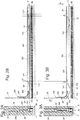
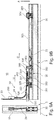
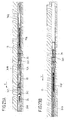
- Figs. 2A, 2B and 3A, 3B show an embodiment of a sealing unit 3 on the door leaf 10 in the retracted position of the seal assembly 30 (FIG. Fig. 2A, 2B ) and in the extended position of the seal assembly 30 (FIG. Fig. 3A, 3B ).
- the sealing unit 3 has a housing 323 and, in this embodiment, two spring elements 31 formed by torsion springs, via which the seal assembly 30 in the form of a along the lower edge of the door leaf 10 extended sealing element is resiliently adjustable.
- the sealing unit 3 has no own (motor) drive, but is adjusted via the locking device 2.
- the transmission element 23 is coupled in the form of the linkage of the locking device 2 via a coupling device 24 in the form of, for example, a Bowden cable with the sealing unit 3 by a guided in a coupling guide 240, flexible power transmission element 241 of the coupling device 24 on pushers 311, each with a Spring end 315 of the spring elements 31 are coupled, attacks and can be adjusted to move the pushers 311.
- the coupling guide 240 is at one of the sealing unit 3 associated end via a support member 242 on the housing 323 of the sealing unit 3 and also at its other end via a stationary to the door 10 arranged (not shown in detail) Bowdenrohrabstützung against the door 10th supported.
- the force transmission element 241 of the coupling device 24 is fixed via a coupling element 230 to the transmission element 23 in the form of the linkage, so that by adjusting the transmission element 23, the force transmission element 241 of the coupling device 24 moves relative to the coupling guide 240 and thereby the pushers 311 can be adjusted.
- the spring elements 31 are each connected to a spring end 315 with an associated thrust element 311 and fixed to a different spring end 314 via a respective fastening element 310 on the housing 323 of the sealing unit 3.
- the spring ends 314, 315 can be changed in position relative to each other, in order in this way the seal assembly 30 between the retracted position ( Fig. 2A, 2B ) and the extended position ( Fig. 3A, 3B ) to move.
- the thrust elements 311 are offset by a distance X, as is clear from the transition from Fig. 2B towards Fig. 3B it can be seen to in this way to pivot the spring ends 314, 315 (under tension of the spring elements 31) to each other and thereby the seal assembly 30 from the retracted position to the extended position to convict.
- the seal assembly 30 protrudes outwardly from the housing 323 of the sealing unit 3 and seals a gap between the door leaf 10 and a bottom 4 on the underside of the door leaf 10, as in particular Fig. 3A is apparent.
- the adjustment of the locking device 2 and the sealing unit 3 takes place in a synchronous manner.
- the locking device 2 is driven to lock the door leaf 10 with the door frame 11 and to the transmission element 23 adjusted in the direction of movement V, as is apparent from Fig. 3B is apparent.
- the seal assembly 30 is extended synchronously and thus the door leaf 10 is sealed relative to the bottom 4.
- the locking device 2 is unlocked by adjusting the transmission element 23 against the direction of movement V, whereby the seal assembly 30 is lifted off the base 4 and placed back in the retracted position.
- the seal assembly 30 In the closed position, the seal assembly 30 is under spring bias of the spring elements 31 on the bottom 4. This allows a tolerance compensation and a compensation of unevenness in the bottom 4. In addition, a readjustment of the sealing unit 3 is not required or at least considerably simplified.
- the movement of the seal assembly 30 can be effected directly by adjusting the transmission element 23 of the locking device 2, as described above with reference to the embodiment according to FIG Figs. 2A, 2B and 3A, 3B explained.
- a tensile force is transmitted via the power transmission element 241 of the coupling device 24 and introduced into the pushers 311, which are thereby displaced by a distance X and the Lower the seal assembly 30 via the spring elements 31.
- the force transmission element 241 is reset against the direction of movement V, so that the seal assembly 30 is lifted due to the spring action of the spring elements 31 again.
- the lowering of the seal assembly 30 to the extended position is independent of the locking means 2, while the lifting for transferring the seal assembly 30 to the retracted position is effected by the locking means 2.
- the seal assembly 30 is supported via a (at least) a spring element 31 on a housing 323 of the sealing unit 3, wherein a spring arm 314 with a fixing element fixedly fixed to the housing 323 and the other spring arm 315 of the spring element 31 formed as a leg spring on a push element 311, which is guided transversely to the adjustment direction A of the seal assembly 30 slidably mounted on the housing 3, is attached.
- the thrust element 311 is in this case supported by a damping element 33 on the housing 323 and thus displaced in a damped manner to the housing 323.
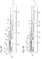
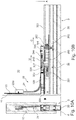
- the sealing unit 3 of the embodiment according to Figs. 4A-4D to 6A-6D has a locking assembly 32 which serves to move the pusher 311 and above the seal assembly 30 in the retracted position (FIG. Fig. 4A ) to lock relative to the housing 323 and thus to hold in the retracted position.
- the locking assembly 32 has for this purpose a blocking element 327 in the form of a pivotable about a pivot axis 328 locking lever which is in the retracted position of the seal assembly 30 latchingly engaged with the associated thrust element 311 and thus holds this in position relative to the housing 323, as out Fig. 4A is apparent.
- the blocking assembly 32 has a pressure element 320 with a shaft 321, which is spring-biased via a spring element 322 in the form of a compression spring to a housing portion 324 of the housing 323 and is connected to a trigger element 326.
- the pressure element 320 is, in a normal position, held by the collar 325 fixedly connected between the housing section 324 and a shaft 321 acting spring element 322, out of the housing 323 at the closing edge of the door leaf 10 outwardly, as for example Fig. 5B is visible, and serves to interact when closing the door leaf 10 with the frame 11 (in particular a frame edge 110 which is opposite the closing edge of the door leaf 10 when the door leaf 10 is closed).
- the pressure element 320 runs when closing the door leaf 10 on the frame edge 110, as in the transition from Fig. 5D in addition Fig. 6D is apparent, and is thereby pressed in an unlocking direction U against the spring force of the spring element 322 in the housing 323.
- the trigger element 326 is moved in the unlocking direction U and acts on the blocking element 327 such that the blocking element 327 is pivoted about the pivot axis 328 and disengaged from the pusher element 311, as can be seen from the sequence of FIGS Fig. 4A towards Fig. 4D is apparent.
- the seal assembly 30 moves automatically due to the spring force of the (biased in the retracted position) spring member 31 in the adjustment direction A down to the bottom 4 and is thus transferred to the extended position.
- the lowering of the seal assembly 30 takes place here due to the damping element 33, for example formed as a gas spring, in a damped manner.
- the lowering of the seal assembly 30 is thus not sudden, but delayed in time, which prevents grinding of the seal assembly 30 on the ground before reaching the fully closed position of the door leaf 10.
- the spring element 31 is coupled in the illustrated embodiment via a slider 312 centered on the spring element 31 with the seal assembly 30 and slidably guided on a sliding guide 313 of the seal assembly 30.
- the slider 312 moves transversely to the adjustment direction A on the slide 313 and thereby compensates for a transverse movement of the pusher 311 when lowering the seal assembly 30 from.
- the lowering of the seal assembly 30 is carried out in this embodiment, thus by interaction of the locking assembly 32 with the door frame 11 and thus basically independent of the locking device 2.
- the lowering takes place here when closing the door leaf 10 immediately upon reaching the closed position.
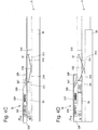
- the locking device 2 In the closed position of the door leaf 10, the locking device 2 is in the locking position and thus locks the door leaf 10 via the locking assemblies 22 and the door lock 21 with the door frame 11, as shown for example in FIG Fig. 6A is shown. If the door leaf 10 is to be opened again, then the locking device 2 is actuated by adjusting the transmission element 23 for unlocking the latch assemblies 22 and the door lock 21, wherein via a coupling device 24 in the form of, for example, a Bowden cable movement of the transmission element 23 also retracting the pusher element 311 in a direction of release U opposite direction of movement B (see Fig. 6C ) causes. Above this, the seal assembly 30 is pulled back to the retracted position, in which the locking member 327 in turn is latched to the pusher 311, as shown in FIG Fig. 4A and 5A to 5D is shown.
- the seal assembly 30 is returned to the retracted position and thus raised.
- the transmission element 23 is driven in the form of the linkage driven by the drive device 20 in such a position that upon renewed closing of the door leaf 10 and upon release of the locking element 327, the seal assembly can be extended again.
- a spring element 31 In the embodiment according to Figs. 4A-4D to 6A-6D only one spring element 31 is shown. However, there may also be two (or more) spring elements 31, each connected to a fastener 310 and a pusher 311, it being generally sufficient to provide a (single) pawl assembly 32 for latching one of the pushers 311.
- Figs. 7A-7C and 8A-8C illustrated embodiment is substantially functionally identical to the embodiment according to Figs. 4A-4D to 6A-6D ,
- a locking assembly 32 is provided which holds the seal assembly 30 in the retracted position (FIG. Figs. 7A to 7C ) and can be triggered by interaction of a pressure element 320 with the door frame 11 to a blocking element 327 to a Swivel pivot axis 328 and thereby release a thrust element 311. Due to the spring action (at least) of a spring element 31, the seal assembly 30 is thereby lowered in a damped manner via a damping element 33.
- the pressure element 320 is spring-biased via a spring element 322 relative to the trigger element 326, and also the trigger element 326 is spring-biased via a spring element 329 relative to the housing 323.
- the pressure element 320 initially acts elastically on the spring element 322 and then block via a shaft 321 on the trigger element 326 and adjusts this in the release direction U to trigger the locking element 327, as in the transition from Fig. 7C towards Fig. 8C is apparent.
- the force transmission element 241 of the coupling device 24 is fixed to a coupling element 243 and connected to the thrust element 311, so that the force transmission element 241 acts on the thrust element 311 when the sealing assembly 30 is reset in the retracted position.
- sealing unit 3 is coupled to the locking device 2 via the coupling device 24, a separate (electromotive) drive on the sealing unit 3 can be dispensed with.
- the adjustment in at least one direction of movement via the drive 20 of the locking device 2, so that the sealing unit 3 is actuated in response to an actuation of the locking device 2.
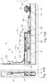
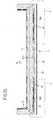
- an adjusting mechanism 35 for adjusting the seal assembly 30 is provided, which is designed as a pinion gear.
- racks 354 extending along the adjustment direction A are fixedly connected to the seal assembly 30 and are engaged with pinions 353 rotatably mounted on the housing 323 of the seal unit 3.
- the pinions 353 are operatively connected to a drive linkage 350 in that the pinions 353 are engaged with toothed sections of the drive linkage 350 such that upon movement of the drive linkage 352 along a direction of movement C directed transversely to the adjustment direction A, the pinions 353 are rotated (synchronously) and above Racks 354 for lowering or raising the seal assembly 30 are driven.
- two racks 354 along the direction of movement C are arranged offset to each other on the seal assembly 30 and are engaged with two associated pinions 353. Forces are thus introduced into the seal assembly 30 at spaced-apart locations.
- the drive linkage 352 is connected to a carriage 350, which is spring-biased via a spring element 351 relative to the housing. Via the carriage 350, the drive linkage 352 for lowering the seal assembly 30 (in the direction of the extended position) in the direction of movement C and for lifting the seal assembly 30 (in the retracted position) against the direction of movement C is movable.
- the sealing unit 3 also has a locking assembly 32 which corresponds to the locking assembly 32 of the embodiment Figs. 7A to 7C and 8A to 8C functionally equivalent.
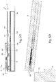
- the seal assembly 30 When the door leaf 10 is open, the seal assembly 30 is in its retracted position according to Figs. 9A, 9B , In this retracted position, the carriage 350 and above the drive linkage 352 is held in position via a lock lever 327 of the lock assembly 32, as shown in FIG Fig. 9B is shown, so that above the seal assembly 30 is locked in its retracted position.
- a pressure element 320 of the locking assembly 32 cooperates with an edge of the door frame 11 and is thereby pressed in an unlocking U in the door leaf 10, whereby a trigger element 326 acts on the pivotable about a pivot axis 328 to the housing 323 locking lever 321 and disengages it from the carriage 350 of the adjustment mechanism 35.
- the locking assembly 32 is thus triggered and the seal assembly 30 released, so that the seal assembly 30, due to the spring bias of the carriage 350 relative to the housing 323, via the meshing with the racks 354 pinion 353 is automatically adjusted to the extended position, as soon as the door leaf 10 is closed.
- the movement of the drive linkage 152 is attenuated here via a damping spring 33 in the form of a gas spring or the like, so that the lowering is not abrupt, but in time (slightly) delayed manner.
- the coupling device 24 acts on a coupling element 243 in the form of a driver, which interacts with the carriage 350 and moves it counter to the direction of movement C.
- the drive linkage 352 is also moved, whereby the pinion 353 is driven and thereby the seal assembly 30 is raised (in Fig. 10B only one pinion 353 is shown, the other is omitted for the sake of clarity).
- the coupling element 243 is in this case via a Spring element 244 biased relative to the housing 323 of the sealing unit 3, so that the return of the coupling element 243 (in the direction of movement C) takes place in spring-assisted manner.
- the seal assembly 30 is raised directly and in coupled manner with the locking device 2, a grinding of the seal assembly 30 at the bottom 4 is avoided.
- the seal assembly 30 is lowered in the direction of the bottom 4 only when the door leaf 10 has reached its closed position, and is immediately raised again when the door leaf 10 is unlocked to open.
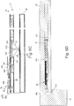
- FIG. 11A, 11B and 12A, 12B Functionally corresponds essentially with the embodiment according to Figs. 9A, 9B and 10A, 10B ,
- a damping spring 33 is provided for biasing the carriage 350 relative to the housing.
- the drive linkage 352 is not continuous, but divided into two linkage sections which are interconnected via a linkage 356 for joint movement.
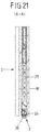
- FIGS. 13 and 14 show schematic views of an embodiment in which a power transmission for adjusting the seal assembly 30 via a link element 36 takes place that is associated with the illustrated embodiment, the seal assembly 30 and is driven directly via the coupling device 24.
- the link element 36 is elastically resiliently connected to the seal assembly 30 via a spring support 361 along the adjustment direction A, so that the seal assembly 30 (slightly) along the adjustment direction A relative to the link element 36 can be adjusted.
- the link element 36 has an oblique to the adjustment direction A extending link 360 into which an engagement member 245 engages in the form of a pin, which is displaceable on a along a direction of movement C on a housing 323 of the sealing unit 3 and arranged above the door leaf 10 coupling element 243 is arranged.
- the coupling element 243 is connected to the force transmission element 241 of the coupling device 24 in connection that the coupling element 243 is moved in a movement of the force transmission element 241 along the direction of movement C.
- the seal assembly 30 is driven both in the adjustment direction A for lowering the seal assembly 30 in the extended position and against the adjustment direction A for retracting the seal assembly 30 in the retracted position via the coupling device 24.
- the force transmission element 241 of the coupling device 24 is moved along the direction of movement C, moved over the coupling element 243 and thereby, due to the link coupling between the coupling element 243 and the link element 36, the seal assembly 30 moved between their different positions.
- the seal assembly 30 is lowered when the coupling element 243 against the direction of movement C from the position according to Fig. 13 in the position according to Fig. 14 is moved. Is, driven by the coupling device 24, the coupling element 243 reversed in the direction of movement C from the position according to Fig. 14 in the position according to Fig. 13 transferred, the seal assembly 30 is retracted.
- the seal assembly 30 is preferably at the bottom 4, wherein due to the spring support 361 between the link element 36 and the seal assembly 30, a positional match between the link element 36 and the seal assembly 30 is possible, thus unevenness in the bottom 4 can be compensated and a Tension in the system is avoided.
- the coupling device 24 may be designed in the manner of a Bowden cable with a guided in a Bowden tube soul. It is also conceivable and possible, as shown schematically in FIGS. 15 and 16 is shown to form the coupling device 24 in the manner of a so-called corner deflection, in which the force transmission element 241 is guided in the form of a flexible, for example made of spring steel strip in a coupling guide 240, as for example in Fig. 16 is shown.
- the power transmission element 241 can be moved within the coupling guide 240, wherein the force transmission element 241 is firmly connected on the one hand with transmission element 23 of the locking device 2 and on the other hand firmly with the coupling element 243 on the part of the sealing unit 3, so that the coupling element 243 via the force transmission element 241 together with the transmission element 23 of the locking device 2 is moved.
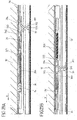
- Figs. 16 to 24A-24C show a further embodiment of a sealing unit 3, which has a seal assembly 30 and is disposed on a lower edge of a door leaf 10 for sealing against a floor.
- the sealing unit 3 is operatively connected to a locking device 2 in the form of a multiple locking, analogous to the above with reference to Fig. 1 has been described.
- the locking device 2 in the form of multiple locking bolt assemblies 22 which can be adjusted together via a transmission element 23 in the form of a linkage to effect a lock between the door 10 and a frame 11 at a plurality of locations when the locking device 2 in a locked position.
- the laying device 2 is operatively connected via a coupling device 24 with the sealing unit 3.
- the coupling device 24 is formed in the illustrated embodiment as a Bowden cable and serves to initiate an adjusting force of the locking device 2 in the sealing unit 3, to effect an adjustment of the seal assembly 30 of the sealing unit 3 between different positions.
- the coupling device 24 may for example also be formed by a corner deflection or by another coupling.
- Figs. 18 to 24A-24C how out Figs. 18 to 24A-24C can be seen, the sealing unit 32 on link elements 36 which are fixedly connected to the adjustable along an adjustment A seal assembly 30 of the sealing unit 3 and a force deflection for adjusting the seal assembly 30 between an extended position ( Fig. 18 ) and a retracted position ( Fig. 19 and 20 ) cause.
- the coupling device 24 in the form of the Bowden cable on a coupling guide in the form of a Bowden sleeve 240 which is supported at the sealing unit 3 associated end within a housing 323 on a support member 242, as in particular Fig. 22 and Fig. 23A is apparent.
- a power transmission element 241 is guided in the form of a soul of the Bowden cable and connected on the part of the sealing unit 3 with a damping element 33, which is formed in the illustrated embodiment, for example as a gas spring or as an oil damper.
- each engagement element 245 is fixedly connected to an associated connection element 34A, 34B in the form of the respective linkage and can be moved by moving the connection element 34A, 34B relative to the respective link element 36.
- each linkage 34A, 34B is spring-biased relative to the housing 323 via an associated spring element 37A, 37B, such that adjustment of the connection elements 34A, 34B in an adjustment direction V for lifting the seal assembly 30 from an extended position (FIG. Fig. 18 ) into a retracted position ( Fig. 19 . 20 ) takes place against the spring bias of the spring elements 37A, 37B.
- each engagement element 245 is in the extended position of the seal assembly 30 in an upper position in a link 360 of the respective link element 36, as is apparent from Fig. 24A is apparent.
- the associated linkage 34A, 34B moved in the adjustment direction V (driven by the locking device 2)
- the engagement member 245 is displaced in the link 360, wherein the engagement member 245 is moved linearly along the adjustment direction V together with the associated connecting element 34A, 34B
- the link element 36 is raised in a stroke direction H, wherein in a further adjustment of the locking device 2, the engagement member 245 can perform a free stroke in the backdrop 360, as in the transition from Fig. 24B towards Fig. 24C (corresponding to the transition from Fig. 19 towards Fig. 20 ) can be seen.
- the seal assembly 30 is lifted in the lifting direction H and thus from the extended position (FIG. Fig. 18 ) in the retracted position ( Fig. 19 . 20 ) adjusted. This occurs when the locking device 2 is adjusted to lock the door leaf 10 to the door frame 11.
- the sealing unit 3 automatically resets itself due to the spring forces of the pretensioned spring elements 37A, 37B, so that the seal assembly 30 is once again extended and comes into abutment with a floor located below the door leaf 10 (corresponding to the extended position according to FIG Fig. 17 ).
- the sealing unit 3 is coupled to a locking device 2 in the form of a turn-tilt hardware such as a patio door or the like.
- a locking device 2 in the form of a turn-tilt hardware such as a patio door or the like.
- a turn-tilt fitting By means of such a turn-tilt fitting, a building door in a pivoting position of Locking device 2 is pivoted about a vertical pivot axis and tilted in a tilted position of the locking device 2 about a horizontal tilt axis, so that the door leaf 10 can be brought into a tilted position.
- the locking device 2 is coupled via a circumferentially on the door leaf 10 rotating linkage 23 with the sealing unit 3, as shown in the sectional view Fig. 28 is apparent.
- the linkage 23 carries locking pins which can be engaged or disengaged by adjusting the linkage 23 with associated strikers on the side of the door frame to pivot the door leaf 10 about a vertical pivot axis and in the tilted position of the locking device in the pivoted position of the locking device 2 2 tilting of the door leaf 10 to allow the horizontal tilt axis.
- the coupling of the linkage 23 of the locking device 2 with the sealing unit 3 takes place in the illustrated embodiment via a coupling device 24 in the form of a driver, the-like Fig. 28 seen - is connected via a fastener 246 fixed to the power transmission element in the form of the linkage 23 of the locking device 2, so that the driver 24 is movable together with the linkage 23.
- adjustment mechanisms in the form of lever mechanism 39 are adjusted via the coupling device 24 in the form of the driver, in order thereby to move the seal assembly 30 of the sealing unit 3 between an extended position (FIG. Fig. 25 ) and a retracted position ( Fig. 26, 27 ) to move.
- the coupling means 24 is coupled in the form of the driver via a first spring element 38 A with a linkage 34.
- An active connection with the two adjusting mechanisms in the form of the lever mechanism 39 is produced via the linkage 34, so that the lever mechanism 39 is actuated by adjusting the linkage 34 and thereby the seal assembly 30 can be adjusted.
- the spring elements 38A, 38B are largely relieved.
- the seal assembly 30 is held in the extended position via the lever mechanism 39 and is pressed into contact with a floor below a lower frame edge 110 of the door frame 11.
- each lever mechanism 39 has a lever member 390 which is pivotally connected to the seal assembly 30 with a lever end 392.
- the lever member 390 is also pivotally connected to a lever 391 which is pivotally connected to a lever end 394, but stationary with the housing 323 of the sealing unit 3.
- the lever element 390 also has on a lever element 390 facing away from the end a coupling pin 393, via which the lever member 390 is coupled to a link engagement 340 of the connecting element 34 in the form of the linkage, so that a tensile force in the adjustment direction V on the connecting element 34 in the form of Linkage leads to an adjustment of the lever member 390.
- the second spring element 38B is tensioned, so that a prestressing with respect to the housing 323 is effected.
- the seal assembly 30 is already retracted. If the locking device 2 is further adjusted, for example, to the locking device 2 from its pivotal position (in which a pivoting of the door leaf 10 about the vertical pivot axis is possible) in a tilted position (in which a tilting of the door leaf 10 about the horizontal tilt axis is possible) cause such an adjustment of the locking device 2 by moving the coupling device 24 in the form of the driver, without the seal assembly 30 is moved further in the stroke direction H. Such a movement of the coupling device 24 causes a further tensioning of the spring element 38 to train, so that due to the elasticity of the spring element 38A, a further adjustment movement of the locking device 2 is compensated.
- the sealing unit 3 In a reverse adjustment of the locking device 2 and thus also the coupling device 24 in the form of the driver, the sealing unit 3 automatically returns, so that the seal assembly 30 automatically, due to the spring forces of the spring elements 38A, 38B, in the extended position ( Fig. 25 ) is lowered.
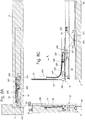
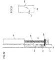
- a locking device 2 in the form of a multiple locking with bolt assemblies 21, 22 is provided, wherein an electromotive drive means 20 is arranged in the form of a spindle drive directly to a power transmission element 23 in the form of a linkage of the locking device 2.
- the drive device 20 is in this case integrated in a profile part of the door leaf 10, as is made Fig. 31 is apparent.
- the building door 1 has an adjusting drive 12, which is integrated horizontally into an upper section of the door leaf 10 and serves to electromotive adjustment of the door leaf 10 between a closed position and an open position.
- Both the adjusting drive 12, which acts on a secondary closing edge of the door frame 11, and the drive device 20 of the locking device 2 are connected to a control device 13, which serves to control the operation of the adjustment 12 and the locking device 2.
- the power transmission element 23 can be adjusted by electric motor in the form of the linkage of the locking device 2, so that synchronously the bolt assemblies 21, 22 of the locking device 2 can be moved. Due to a coupling via a coupling device 24, for example in the form of a Bowden cable or a corner drive, an adjustment of a seal assembly of a tightness 3 can also take place.
- the drive device 20 is designed as a spindle drive, which - as in Fig. 32 illustrated - an electric motor driven spindle 201 and having a spindle 200 in threaded engagement with the spindle nut 201.
- the spindle nut 201 can be moved longitudinally along the spindle 200 to thereby move the rod 23 coupled to the spindle nut 201 linearly to the door leaf 10.
- the spindle nut 201 is connected to a closing element 202, which serves as a closing aid.
- a guideway 103 is formed, which may be curved (as in the illustrated embodiment) or alternatively may be formed as an inclined plane and with a pin member 111 on the side of the door frame 11 cooperates to assist in closing the door leaf 10 in the last phase of the closing movement of Door leaf 10 provide.
- the pin member 111 on the door frame 11 - immediately before the door leaf 10 is fully closed - in engagement with the guide track 203 of the closing element 202.
- the pin member 111 be brought into engagement with the closing element 202 and thereby the door leaf 10 are pulled towards the door frame 11, so that a final path for retracting the door leaf 10 in the door frame 11 can be supported by the electric drive motor 20.
- Figs. 34A, 34B and 35A, 35B show a further embodiment of a sealing unit 3, the functionally largely the embodiment according to Fig. 25-29 corresponds, so that reference should also be made to the above.
- a seal assembly 30 is connected to a lever member 390 of a lever mechanism 39 and via the lever mechanism 39 between a retracted position ( Fig. 34B ) and an extended position ( Fig. 34A ) adjustable.
- a connecting element 34 is biased in the form of a linkage via a spring element 38C in the form of a compression spring against a fixedly connected to the housing 323 of the seal 3 housing portion in that the spring element 38C between the housing portion 323B and one fixed to the connecting element 34th connected carrier portion 344 is supported and is tensioned in an adjustment of the connecting element 34 in an adjustment direction V on pressure.
- the spring element 38C is tensioned so that the seal assembly 30 can be returned toward the extended position assisted by the biasing spring force of the spring element 38C (thus, in the embodiment, a spring element 38B at the other end of the connection element 34 may be used the embodiment according to Fig. 25-29 be waived).
- Another spring 38D is provided between portions of the connecting member 34 and serves for elastic clearance compensation.
- the connecting element 34 is according to the embodiment Figs. 34A, 34B and 35A, 35B connected to a coupling piece 341 in the form of a locking element, which serves for producing a releasable coupling with the coupling device 24.
- the coupling piece 341 has a latching head 342 arranged on a limb 346 for latching with a latching opening 323A on the housing 323, which is elastically adjustable and connected to an actuating section 343 in the form of a tension spring, so that actuation of the actuating section 343 effects an adjustment of the latching head 342 can be.
- a form-fitting element 345 is formed, which serves for producing the coupling with a coupling element 243 of the coupling device 24.
- the coupling device 24 is coupled to the coupling piece 341 and above with the connecting element 34 of the sealing unit 3. This is effected in that the locking head 342 is in abutment with a surface of the housing 323 and the leg 346 carrying the locking head 342 is elastically displaced inwardly toward another, opposite leg 347 of the coupling piece 341, so that a positive connection between the coupling element 243 the coupling device 24 and the interlocking element 345 of the coupling piece 341 is made, as is apparent from Fig. 35A is apparent.
- the coupling piece 341 is thus moved together with the coupling device 24 and the seal assembly 30 thus retracted.
- the sealing unit 3 Due to the latching via the coupling piece 341, the sealing unit 3 is held in this position, whereby the fact that the leg 346 is removed from the opposite leg 347 and thus the positive-locking element 345 is displaced outwards releases the positive connection between the coupling device 24 and the coupling piece 341 is and the coupling device 24 can be adjusted independently of the sealing unit 3 in the adjustment direction V.
- the with the Coupling device 24 connected locking device 2 can thus be adjusted independently of the sealing unit 3, for example, to achieve an unlocked position or to move the locking device 2 between different unlocked positions (for example, a pivotal position and a tilted position).
- the coupling device 24 moves with the coupling element 143 into the receptacle formed between the legs 346, 347 and reaches the actuating section 343
- Form of the tension spring in interaction which causes the locking head 342 lifted from the locking opening 323A of the housing 323 and the latch is thus canceled.
- the seal assembly 30 is thus no longer held in the retracted position.
- the seal assembly 30 can thus be extended by movement of the locking device 2 against the adjustment direction V and supported by the biasing spring action of the tensioned in the retracted position spring 38C again.
- An assembly of the type described above can be used in very different building doors, for example, interior doors or exterior doors.
- An assembly of the type described here can be used not only for sealing a door leaf relative to the floor, but also, for example, for sealing against the door frame.
Landscapes
- Engineering & Computer Science (AREA)
- Civil Engineering (AREA)
- Structural Engineering (AREA)
- Mechanical Engineering (AREA)
- Specific Sealing Or Ventilating Devices For Doors And Windows (AREA)
Abstract
Eine Baugruppe einer Gebäudetür (1) umfasst eine an einem Türflügel (10) anzuordnende Dichteinheit (3), die ein Gehäuse (323) und eine zwischen einer ersten, eingefahrenen Stellung und einer zweiten, ausgefahrenen Stellung entlang einer Verstellrichtung (A) zu dem Gehäuse (323) bewegbare Dichtungsbaugruppe (30) zum zumindest teilweisen Abdichten des Türflügels (10) in einer geschlossenen Stellung gegenüber einem Boden (4) und/oder einem Türrahmen (11) aufweist. Eine an dem Türflügel (10) anzuordnende, zwischen einer entriegelnden Stellung und einer verriegelnden Stellung verstellbare Verriegelungseinrichtung (2) dient zum Verriegeln des Türflügels (10) in der geschlossenen Stellung. Zusätzlich ist eine Kopplungseinrichtung (24) vorgesehen, die zum Koppeln der Verriegelungseinrichtung (2) mit der Dichteinheit (3) derart dient, dass bei einem Verstellen der Verriegelungseinrichtung (2) aus der entriegelnden Stellung in die verriegelnde Stellung die Dichtungsbaugruppe (30) in die zweite, ausgefahrene Stellung und/oder bei einem Verstellen der Verriegelungseinrichtung (2) aus der verriegelnden Stellung in die entriegelnde Stellung in die erste, eingefahrene Stellung bewegt wird.An assembly of a building door (1) comprises a sealing unit (3) to be arranged on a door leaf (10) comprising a housing (323) and one between a first, retracted position and a second, extended position along an adjustment direction (A) to the housing (323) movable seal assembly (30) for at least partially sealing the door leaf (10) in a closed position relative to a bottom (4) and / or a door frame (11). A locking device (2) to be arranged on the door leaf (10) and adjustable between an unlocking position and a locking position serves to lock the door leaf (10) in the closed position. In addition, a coupling device (24) is provided, which serves for coupling the locking device (2) with the sealing unit (3) such that upon an adjustment of the locking device (2) from the unlocking position to the locking position, the seal assembly (30) into the second, extended position and / or upon adjustment of the locking device (2) is moved from the locking position to the unlocked position in the first, retracted position.
Description
Die Erfindung betrifft eine Baugruppe einer Gebäudetür nach dem Oberbegriff des Anspruchs 1.The invention relates to an assembly of a building door according to the preamble of
Eine derartige Baugruppe umfasst eine an einem Türflügel anzuordnende Dichteinheit, die ein Gehäuse und eine zwischen einer ersten, eingefahrenen Stellung und einer zweiten, ausgefahrenen Stellung entlang einer Verstellrichtung zu dem Gehäuse bewegbare Dichtungsbaugruppe zum zumindest teilweisen Abdichten des Türflügels in einer geschlossenen Stellung gegenüber einem Boden und/oder einem Türrahmen aufweist. An dem Türflügel ist zudem eine zwischen einer entriegelnden Stellung und einer verriegelnden Stellung verstellbare Verriegelungseinrichtung anzuordnen, die zum Verriegeln des Türflügels in der geschlossenen Stellung dient.Such an assembly comprises a sealing unit to be arranged on a door leaf, comprising a housing and a seal assembly movable between a first, retracted position and a second, extended position along an adjustment direction to the housing for at least partially sealing the door leaf in a closed position relative to a floor and / or has a door frame. On the door wing is also to arrange an adjustable between an unlocking position and a locking position locking device, which serves to lock the door leaf in the closed position.
Bei herkömmlichen Gebäudetüren, zum Beispiel Innentüren oder Außentüren an einem Gebäude, ist ein Türflügel beispielsweise verschwenkbar an einem Türrahmen angeordnet. Zwischen dem Türflügel und einem Boden des Gebäudes besteht hierbei üblicherweise ein Spalt, der erforderlich ist, um ein einfaches, ungehindertes Bewegen des Türflügels gegenüber dem Türrahmen zu ermöglichen.In conventional building doors, for example, interior doors or exterior doors to a building, a door is pivotally mounted, for example, on a door frame. There is usually a gap between the door leaf and a floor of the building, which is required in order to allow a simple, unhindered movement of the door leaf relative to the door frame.
Bei einer Gebäudetür kann es sich hierbei beispielsweise auch um eine Terrassentür handeln und diesbezüglich um eine Schwenktür oder auch eine Schiebetür. Insbesondere bei einer Gebäudeaußentür, aber gegebenenfalls auch bei einer Gebäudeinnentür, kann erwünscht sein, dass der Türflügel in seiner geschlossenen Stellung zumindest weitestgehend gegenüber dem Türrahmen und dem Boden abgedichtet ist, um einen Luftzug und eine Schallübertragung über die Gebäudetür zu unterbinden. Hierzu dient die an dem Türflügel angeordnete Dichteinheit, deren Dichtungsbaugruppe insbesondere bei geschlossenem Türflügel so verstellbar ist, dass der Türflügel gegenüber dem Türrahmen und/oder dem Boden abgedichtet ist. Dient die Dichteinheit zum Beispiel als Bodendichtung, so kann die Dichtungsbaugruppe bei geschlossenem Türflügel abgesenkt werden, um auf diese Weise einen Spalt zwischen dem Türflügel und dem Boden zu verschließen und somit einen Luftzug und eine Schallübertragung über den Spalt zu unterdrücken.In the case of a building door, this can also be, for example, a patio door and, in this regard, a swing door or even a sliding door. Particularly in the case of a building exterior door, but possibly also in the case of a building interior door, it may be desirable for the door leaf in its closed position to be at least largely sealed off from the door frame and the floor in order to prevent draft and sound transmission through the building door. This purpose is served by the sealing unit arranged on the door leaf, the sealing assembly of which is adjustable in particular when the door leaf is closed so that the door leaf is sealed off from the door frame and / or the floor. For example, if the sealing unit serves as a bottom seal, then the seal assembly can be lowered with the door closed, thus closing a gap between the door leaf and the floor and thus suppressing draft and sound transmission across the gap.
Eine Dichteinheit dieser Art soll einfach zu montieren sein, dabei aber auch eine wirkungsvolle Abdichtung bei geschlossenem Türflügel ermöglichen. Zudem muss die Dichtungsbaugruppe so verstellbar sein, dass ein ungehindertes Öffnen und Schließen des Türflügels ohne Schleifen der Dichtungsbaugruppe am Boden oder am Türrahmen möglich ist.A sealing unit of this type should be easy to assemble, but also allow an effective seal with the door closed. In addition, the seal assembly must be adjustable so that unimpeded opening and closing of the door leaf without loosening the seal assembly on the floor or on the door frame is possible.
Bei einem aus der
Bei einer aus der
Die
Bei einer aus der
Aufgabe der vorliegenden Erfindung ist es, eine Baugruppe einer Gebäudetür sowie eine Gebäudetür zur Verfügung zu stellen, die auf einfache Weise ein zuverlässiges Verstellen einer Dichtungsbaugruppe der Dichteinheit in Abhängigkeit von der Schließstellung des Türflügels ermöglichen.Object of the present invention is to provide an assembly of a building door and a building door available that allow a simple way a reliable adjustment of a seal assembly of the sealing unit in response to the closed position of the door leaf.
Diese Aufgabe wird durch einen Gegenstand mit den Merkmalen des Anspruchs 1 gelöst.This object is achieved by an article having the features of
Demnach weist die Baugruppe eine Kopplungseinrichtung zum Koppeln der Verriegelungseinrichtung mit der Dichteinheit derart auf, dass bei einem Verstellen der Verriegelungseinrichtung aus der entriegelnden Stellung in die verriegelnde Stellung die Dichtungsbaugruppe in die zweite, ausgefahrene Stellung und/oder bei einem Verstellen der Verriegelungseinrichtung aus der verriegelnden Stellung in die entriegelnde Stellung in die erste, eingefahrene Stellung bewegt wird.Accordingly, the assembly has a coupling device for coupling the locking device with the sealing unit such that upon an adjustment of the locking device from the unlocking position to the locking position, the seal assembly in the second, extended position and / or in an adjustment of the locking device from the locking position is moved to the unlocked position in the first, retracted position.
Im Rahmen der Baugruppe ist vorgesehen, dass die Dichteinheit und die Verriegelungseinrichtung einer Gebäudetür miteinander gekoppelt sind. Über die vorzugsweise zur mechanischen Kraftübertragung ausgebildete Kopplungseinrichtung wird somit eine Verstellbewegung der Verriegelungseinrichtung auf die Dichteinheit übertragen, sodass bei einem Verriegeln der Verriegelungseinrichtung die Dichteinheit in die zweite, ausgefahrene Stellung und/oder bei einem Entriegeln der Verriegelungseinrichtung die Dichteinheit in die erste, eingefahrene Stellung überführt wird. Das Verstellen der Dichteinheit erfolgt somit in Abhängigkeit von einem Verstellen der Verriegelungseinrichtung, was ermöglicht, die Dichteinheit ohne eigenen Antrieb auszugestalten.As part of the assembly is provided that the sealing unit and the locking device of a building door are coupled together. An adjustment movement of the locking device is thus transmitted to the sealing unit via the coupling device, which is preferably designed for the mechanical transmission of force, so that when the locking device is locked, the sealing unit transfers the sealing unit into the second retracted position in the second, extended position and / or when the locking device is unlocked becomes. The adjustment of the sealing unit thus takes place in dependence on an adjustment of the locking device, which makes it possible to design the sealing unit without its own drive.
Die vorliegende Erfindung geht von der Erkenntnis aus, dass die Betätigung der Dichteinheit und die Betätigung der Verriegelungseinrichtung prinzipiell gleichzeitig zu erfolgen haben. So soll beim Schließen der Gebäudetür die Verriegelungseinrichtung den Türflügel zum Beispiel mit einem Türrahmen verriegeln, sobald die geschlossene Stellung erreicht ist. In der geschlossenen Stellung soll auch die Dichtungsbaugruppe der Dichteinheit in die zweite, ausgefahrene Stellung überführt werden, um den Türflügel zum Beispiel gegenüber einem Boden abzudichten und so einen Spalt zwischen dem Türflügel und dem Boden zumindest weitestgehend zu verschließen. Das Verstellen der Verriegelungseinrichtung und das Bewegen der Dichtungsbaugruppe in die zweite, ausgefahrene Stellung sollen somit jeweils nach Erreichen der geschlossenen Stellung erfolgen, was ermöglicht, das Bewegen der Dichtungsbaugruppe in Abhängigkeit von der und gesteuert durch die Verriegelungseinrichtung durchzuführen.The present invention is based on the recognition that the actuation of the sealing unit and the actuation of the locking device in principle have to be done simultaneously. Thus, when closing the building door, the locking device should lock the door leaf, for example, with a door frame as soon as the closed position is reached. In the closed position and the seal assembly of the sealing unit should be transferred to the second, extended position to seal the door, for example, against a floor and thus to close a gap between the door and the floor at least as far as possible. The adjustment of the locking device and the movement of the seal assembly in the second, extended position are thus each carried out after reaching the closed position, which makes it possible to perform the movement of the seal assembly in response to and controlled by the locking device.
Weil die Verriegelungseinrichtung über die Kopplungseinrichtung mit der Dichteinheit gekoppelt ist, können Verstellkräfte von der Verriegelungseinrichtung auf die Dichteinheit übertragen werden, was ermöglicht, auf einen separaten Antrieb für die Dichteinheit zu verzichten.Because the locking device is coupled via the coupling device with the sealing unit, can be adjusting forces from the locking device to the sealing unit be transferred, which makes it possible to dispense with a separate drive for the sealing unit.
Die Verriegelungseinrichtung kann in einfacher Ausgestaltung als an dem Türflügel anzuordnendes Türschloss ausgebildet sein. Das Türschloss weist beispielsweise eine sogenannte Schließfalle auf, die beim Schließen der Tür in Eingriff mit einer zugeordneten Schließaussparung am Türrahmen schnappt und zum Beispiel durch einen Türgriff manuell oder auch durch eine elektromotorische Antriebseinrichtung elektrisch verstellt werden kann. Über die Kopplungseinrichtung ist die Verriegelungseinrichtung mit der Dichteinheit verbunden, sodass eine Betätigung der Verriegelungseinrichtung auch ein Bewegen der Dichtungsbaugruppe der Dichteinheit auslöst.The locking device may be formed in a simple configuration as to be arranged on the door leaf door lock. The door lock has, for example, a so-called latch, which snaps when closing the door into engagement with an associated locking recess on the door frame and can be adjusted electrically, for example by a door handle manually or by an electric motor drive means. About the coupling device, the locking device is connected to the sealing unit, so that an actuation of the locking device also triggers a movement of the sealing assembly of the sealing unit.
In anderer Ausgestaltung weist die Verriegelungseinrichtung eine (elektromotorische) Antriebseinrichtung, ein oder mehrere Riegelbaugruppen mit verstellbaren Riegelelementen und ein durch die Antriebseinrichtung antreibbares Übertragungselement zum Verstellen der Riegelelemente der Riegelbaugruppe auf. Das Übertragungselement kann beispielsweise als an dem Türflügel verstellbares Gestänge ausgebildet sein und ist vorzugsweise über die Kopplungseinrichtung mit der Dichteinheit gekoppelt. Die Antriebseinrichtung dient dazu, das Übertragungselement zu verstellen, wobei über die Kopplungseinrichtung eine Verstellkraft auch auf die Dichteinheit übertragen werden kann, um auf diese Weise die Dichtungsbaugruppe zwischen der ersten, eingefahrenen Stellung und der zweiten, ausgefahrenen Stellung zu bewegen.In another embodiment, the locking device has an (electromotive) drive device, one or more latch assemblies with adjustable locking elements and a drive element driven by the transmission element for adjusting the locking elements of the latch assembly. The transmission element can be designed, for example, as a rod which can be adjusted on the door leaf and is preferably coupled to the sealing unit via the coupling device. The drive means serves to adjust the transmission element, wherein via the coupling means an adjusting force can also be transmitted to the sealing unit to move in this way the seal assembly between the first, retracted position and the second, extended position.
Die Verriegelungseinrichtung kann beispielsweise als sogenannte Mehrfachverriegelung mit mehreren Riegelbaugruppen mit je einem verstellbaren Riegelelement ausgebildet sein. Über die (elektromotorische) Antriebseinrichtung können die Riegelbaugruppen durch Verstellen des Übertragungselements synchron verstellt werden, wobei über die mit dem Übertragungselement gekoppelte Kopplungseinrichtung auch die Dichteinheit betätigt und die Dichtungsbaugruppe der Dichteinheit somit in Abhängigkeit von der Stellung der Verriegelungseinrichtung verstellt wird. Eine solche Mehrfachverriegelung kann beispielsweise bei einer Gebäudetür in Form einer Haustür zum Einsatz kommen.The locking device may for example be designed as a so-called multiple locking with multiple latch assemblies, each with an adjustable locking element. By means of the (electromotive) drive device, the bolt assemblies can be adjusted synchronously by adjusting the transmission element, the sealing unit also being actuated via the coupling device coupled to the transmission element and the sealing assembly of the sealing unit thus adjusted as a function of the position of the locking device. Such a multi-point lock can be used, for example, in the case of a building door in the form of a front door.
Die Verriegelungseinrichtung kann, alternativ, aber auch beispielsweise durch einen sogenannten Dreh-Kipp-Beschlag verwirklicht sein, mittels dessen eine Tür oder ein Fenster, zum Beispiel eine Terrassentür, zwischen einer verriegelten Stellung, einer Schwenkstellung (in der ein Verschwenken eines Flügels um eine vertikale Schwenkachse möglich ist) und einer Kippstellung (in der ein Verkippen des Flügels um eine horizontale Kippachse möglich ist) gebracht werden kann.The locking device can, alternatively, but also for example by a so-called turn-tilt fitting be realized by means of which a door or a window, for example a patio door, between a locked position, a pivotal position (in a pivoting of a wing to a vertical swivel axis is possible) and a tilted position (in which a tilting of the wing about a horizontal tilting axis is possible) can be brought.
Die Kopplungseinrichtung kann beispielsweise als Bowdenzug ausgebildet sein. In diesem Fall ist eine Bowdenhülle beispielsweise an dem Türflügel abgestützt, während eine in der Bowdenhülle geführte Seele des Bowdenzugs einerseits mit dem Übertragungselement der Verriegelungseinrichtung und andererseits mit der Dichteinheit verbunden ist, sodass durch Verstellen der Seele des Bowdenzugs gegenüber der Bowdenhülle Verstellkräfte von dem Übertragungselement der Verriegelungseinrichtung auf die Dichteinheit übertragen werden können.The coupling device may be formed, for example, as a Bowden cable. In this case, a Bowden sheath, for example, supported on the door, while a guided in the Bowden soul of the Bowden cable is connected on the one hand with the transmission element of the locking device and on the other hand with the sealing unit, so by adjusting the soul of the Bowden cable relative to the Bowden sheath Verstellkräfte of the transmission element of Locking device can be transferred to the sealing unit.
Alternativ kann die Kopplungseinrichtung auch als sogenannte Eckumlenkung ausgebildet sein, mit einem in einer Kopplungsführung geführten flexiblen Kraftübertragungselement. Mittels einer solchen Eckumlenkung können Kräfte beispielsweise von einer senkrechten Bewegungsrichtung, entlang derer das Übertragungselement in Form des Gestänges der Verriegelungseinrichtung zum Beispiel entlang der Schließkante des Türflügels zu bewegen ist, in eine horizontale Bewegungsrichtung entlang der Unterkante des Türflügels umgelenkt werden. Das Kraftübertragungselement kann beispielsweise als flexibler Streifen ausgebildet sein, zum Beispiel gefertigt aus Federstahl, der entlang der Kopplungsführung verstellbar ist, wobei die Kopplungsführung sich entlang einer gekrümmten Bahn erstreckt und somit Kräfte über das Kraftübertragungselement umgelenkt werden.Alternatively, the coupling device can also be designed as a so-called corner drive, with a guided in a coupling guide flexible power transmission element. For example, by means of such a corner drive forces can be deflected in a horizontal direction of movement along the lower edge of the door leaf from a vertical direction of movement, along which the transmission element in the form of the rod of the locking device to move along the closing edge of the door. The power transmission element may be formed, for example, as a flexible strip, for example made of spring steel, which is adjustable along the coupling guide, wherein the coupling guide extends along a curved path and thus forces are deflected via the force transmission element.
Wiederum alternativ ist die Kopplungseinrichtung als Mitnehmer zum Koppeln der Verriegelungseinrichtung mit der Dichteinheit ausgebildet. Der Mitnehmer ist derart ausgestaltet, dass beispielsweise bei einer Bewegung eines Übertragungselements in Form eines Gestänges der Verriegelungseinrichtung eine Verstellkraft in die Dichteinheit zum Verstellen der Dichtungsbaugruppe eingeleitet und insofern ein Verstellmechanismus der Dichteinheit mitgenommen wird.Again alternatively, the coupling device is designed as a driver for coupling the locking device with the sealing unit. The driver is configured such that, for example, during a movement of a transmission element in the form of a linkage of the locking device, an adjusting force is introduced into the sealing unit for adjusting the seal assembly and insofar an adjusting mechanism of the sealing unit is taken.
In einer Ausgestaltung ist ein Verstellmechanismus der Dichteinheit vollständig in das Gehäuse der Dichteinheit integriert. Die Kopplungseinrichtung, beispielsweise in Form eines Bowdenzugs oder einer Eckumlenkung, erstreckt sich beispielsweise an einem Ort in das Gehäuse der Dichteinheit hinein und ist innerhalb des Gehäuses mit dem Verstellmechanismus der Dichteinheit gekoppelt.In one embodiment, an adjusting mechanism of the sealing unit is completely integrated in the housing of the sealing unit. The coupling device, for example in the form of a Bowden cable or a corner drive, for example, extends at a location into the housing of the sealing unit and is coupled within the housing with the adjusting mechanism of the sealing unit.
In einer Ausgestaltung weist die Dichteinheit ein oder mehrere Federelemente zum Vorspannen der Dichtungsbaugruppe gegenüber dem Gehäuse in Richtung der ersten, eingefahrenen Stellung oder der zweiten, ausgefahrenen Stellung auf. Über ein oder mehrere Federelemente wird somit das Bewegen der Dichtungsbaugruppe in Richtung der ersten, eingefahrenen Stellung oder der zweiten, ausgefahrenen Stellung federmechanisch unterstützt, sodass die Dichtungsbaugruppe zum Beispiel in die eine Richtung über eine über die Kopplungseinrichtung in Form des Bowdenzugs übertragene Zugkraft (entgegen der Wirkung der Federelemente) und in die andere Richtung durch Federkräfte der Federelemente verstellt werden kann.In one embodiment, the sealing unit has one or more spring elements for biasing the seal assembly relative to the housing in the direction of the first, retracted position or the second, extended position. The movement of the seal assembly in the direction of the first, retracted position or the second, extended position is thus supported spring-mechanically via one or more spring elements, so that the seal assembly, for example, in one direction via a transmitted via the coupling device in the form of the Bowden cable tensile force (contrary to Effect of the spring elements) and can be adjusted in the other direction by spring forces of the spring elements.
Über ein oder mehrere Federelemente kann auch eine Elastizität an der Dichtungsbaugruppe bereitgestellt werden, die ermöglicht, zum Beispiel Unebenheiten im Boden oder Toleranzen im Verstellsystem auszugleichen, sodass die Dichtungsbaugruppe bei geschlossenem Türflügel zuverlässig zum Beispiel am Boden anliegen kann. Eine aufwendige Nachjustierung der Dichtungsbaugruppe und des Verstellsystems der Dichteinheit ist dadurch nicht mehr erforderlich.An elasticity on the seal assembly can also be provided via one or more spring elements, which makes it possible, for example, to compensate for unevenness in the ground or tolerances in the adjustment system, so that the seal assembly can reliably rest on the ground, for example, when the door is closed. A complex readjustment of the seal assembly and the adjustment of the sealing unit is no longer required.
Über ein Federelement, zum Beispiel in Form einer als Zugfeder ausgebildeten Schraubfeder, kann - in einer Ausgestaltung - die Kopplungseinrichtung auch mit einem Verstellmechanismus zum Verstellen der Dichtungsbaugruppe zwischen der eingefahrenen Stellung und der ausgefahrenen Stellung gekoppelt sein. Beispielsweise kann die Kopplungseinrichtung über ein erstes Federelement (zum Beispiel in Form einer als Zugfeder ausgebildeten Schraubfeder) mit einem ersten Ende eines Verbindungselements, das mit einem Verstellmechanismus zum Verstellen der Dichtungsbaugruppe (zum Beispiel in Form eines Hebelgetriebes) verbunden ist, gekoppelt sein. Ein zweites Ende des Verbindungselements kann demgegenüber über ein zweites Federelement (zum Beispiel in Form einer als Zugfeder ausgebildeten Schraubfeder) gegenüber dem Gehäuse federvorgespannt sein.By way of a spring element, for example in the form of a helical spring designed as a tension spring, the coupling device can-in one embodiment-also be coupled with an adjusting mechanism for adjusting the seal assembly between the retracted position and the extended position. For example, the coupling device can be coupled via a first spring element (for example in the form of a helical spring designed as a tension spring) to a first end of a connecting element which is connected to an adjusting mechanism for adjusting the seal assembly (for example in the form of a lever mechanism). In contrast, a second end of the connecting element can be spring-biased relative to the housing via a second spring element (for example in the form of a helical spring designed as a tension spring).
Ein Federelement kann somit, in einer Ausgestaltung, im Kraftübertragungsstrang zwischen der Kopplungseinrichtung und dem Verstellmechanismus der Dichteinheit angeordnet sein, sodass Kräfte über das Federelement in den Verstellmechanismus eingeleitet werden können.A spring element can thus, in one embodiment, be arranged in the power transmission line between the coupling device and the adjusting mechanism of the sealing unit, so that forces can be introduced into the adjusting mechanism via the spring element.
Das Federelement kann, in einer Ausgestaltung, beispielsweise als auf Zug zu spannende Schraubfeder ausgebildet sein.The spring element can, in one embodiment, be designed, for example, as a tension-to-tension helical spring.
In einer Ausgestaltung ist das Federelement beispielsweise als Schenkelfeder mit einem ersten Federende in Form eines ersten Schenkels und einem zweiten Federende in Form eines zweiten Schenkels ausgebildet. Das erste Federende kann hierbei beispielsweise über ein Befestigungselement an dem Gehäuse ortsfest festgelegt sein, während das zweite Federende mit einem zu dem Gehäuse (insbesondere quer zur Verstellrichtung) verstellbaren Schubelement verbunden ist. Zum Verstellen der Dichtungsbaugruppe zwischen der ersten, eingefahrenen Stellung und der zweiten, ausgefahrenen Stellung wird das Schubelement bewegt, zum Beispiel über die Kopplungseinrichtung und darüber eingeleitete Verstellkräfte oder über Federkräfte der Federelemente.In one embodiment, the spring element is designed for example as a leg spring with a first spring end in the form of a first leg and a second spring end in the form of a second leg. In this case, the first spring end can be fixed in place on the housing, for example via a fastening element, while the second spring end is connected to a push element which is adjustable relative to the housing (in particular transversely to the adjustment direction). For adjusting the seal assembly between the first retracted position and the second extended position, the pusher is moved, for example, via the coupling means and adjustment forces introduced therefrom or via spring forces of the spring members.
Die Kopplungseinrichtung kann beispielsweise an dem Schubelement angreifen, um Verstellkräfte von der Verriegelungseinrichtung in die Dichteinheit einzuleiten und die Dichtungsbaugruppe in Richtung der ersten, eingefahrenen Stellung oder in Richtung der zweiten, ausgefahrenen Stellung zu verstellen.For example, the coupling means may engage the pusher member to introduce adjustment forces from the latching means into the sealing unit and to adjust the seal assembly towards the first retracted position or towards the second extended position.
Ist das Federelement beispielsweise als Schenkelfeder ausgestaltet, so sind das erste Federende und das zweite Federende vorzugsweise zueinander abgewinkelt und winklig zueinander verstellbar. Über die Federenden ist das Federelement (entlang der Verstellrichtung der Dichtungsbaugruppe) zu dem Gehäuse abgestützt, während mittig zwischen den Federenden, beispielsweise am Orte einer Federwicklung, in einer Ausgestaltung ein Gleitelement angeordnet ist, über das das Federelement quer zur Verstellrichtung gleitend an der Dichtungsbaugruppe geführt ist, sodass bei einem Bewegen der Dichtungsbaugruppe eine Querbewegung des Schubelements ausgeglichen werden kann. Die Dichtungsbaugruppe kann hierzu eine geeignete Gleitführung aufweisen, an der der mit dem Federelement verbundene Gleiter gleitend geführt ist.If the spring element is designed, for example, as a leg spring, then the first spring end and the second spring end are preferably angled relative to each other and angularly adjustable relative to one another. About the spring ends, the spring element (along the adjustment of the seal assembly) is supported to the housing, while in the middle between the spring ends, for example at the location of a spring winding, in one embodiment, a sliding element is arranged over which the spring element guided transversely to the adjustment sliding on the seal assembly is such that when moving the seal assembly, a transverse movement of the pusher can be compensated. The seal assembly may for this purpose have a suitable sliding guide on which the slider connected to the spring element is slidably guided.
Denkbar ist in einer Ausgestaltung, dass eine Verstellbewegung der Verriegelungseinrichtung zu einem Bewegen der Dichtungsbaugruppe sowohl aus der ersten, eingefahrene Stellung in die zweite, ausgefahrene Stellung als auch umgekehrt aus der zweiten, ausgefahrenen Stellung in die erste, eingefahrene Stellung führt. Wird die Verriegelungseinrichtung in ihre verriegelnde Stellung überführt, wird in diesem Fall die Dichtungsbaugruppe aus dem Gehäuse der Dichteinheit ausgefahren, um zum Beispiel einen Spalt zwischen dem Türflügel und einem Boden abzudichten. Wird umgekehrt die Verriegelungseinrichtung aus der verriegelnden Stellung in die entriegelnde Stellung überführt, wird die Dichtungsbaugruppe angehoben und in die erste, eingefahrene Stellung überführt, in der die Dichtungsbaugruppe zumindest teilweise in das Gehäuse der Dichteinheit eingezogen ist. Eine Bewegung des Übertragungselements der Verriegelungseinrichtung wird in diesem Fall somit (unmittelbar) in eine Bewegung der Dichtungsbaugruppe der Dichteinheit umgesetzt.It is conceivable in one embodiment that an adjusting movement of the locking device leads to a movement of the seal assembly both from the first, retracted position to the second, extended position and vice versa from the second, extended position to the first, retracted position. In this case, when the locking device is transferred to its locking position, the seal assembly is extended out of the housing of the sealing unit, for example to seal a gap between the door leaf and a floor. Conversely, if the locking device is transferred from the locking position to the unlocking position, the seal assembly is lifted and transferred to the first, retracted position in which the seal assembly is at least partially retracted into the housing of the sealing unit. A movement of the transmission element of Locking device is thus implemented (directly) in a movement of the sealing assembly of the sealing unit in this case.
In anderer Ausgestaltung wird eine Verstellbewegung der Verriegelungseinrichtung nur in eine Richtung in eine Bewegung der Dichtungsbaugruppe umgesetzt, zum Beispiel zum Überführen der Dichtungsbaugruppe aus der zweiten, ausgefahrenen Stellung in die erste, eingefahrene Stellung bei Entriegelung der Verriegelungseinrichtung. In die andere Richtung erfolgt die Bewegung der Dichtungsbaugruppe hingegen unabhängig von der Verriegelungseinrichtung, gesteuert zum Beispiel in Abhängigkeit von der Türbewegung.In another embodiment, an adjusting movement of the locking device is implemented only in one direction in a movement of the seal assembly, for example, for transferring the seal assembly from the second, extended position to the first, retracted position when unlocking the locking device. In the other direction, however, the movement of the seal assembly is independent of the locking device, controlled, for example, depending on the door movement.
Um ein Schleifen der Dichtungsbaugruppe aufgrund eines zu plötzlichen Ausfahrens der Dichtungsbaugruppe in die zweite, ausgefahrene Stellung zu verhindern, kann das Schubelement beispielsweise über ein Dämpfungselement, zum Beispiel in Form einer Gasdruckfeder oder dergleichen, mit dem Gehäuse verbunden sein. Über das Dämpfungselement wird eine Bewegung des Schubelements somit gedämpft, sodass auch die Bewegung der Dichtungsbaugruppe in gedämpfter Weise erfolgt und ein Verstellen der Dichtungsbaugruppe insbesondere in Richtung der zweiten, ausgefahrenen Stellung somit zeitlich verzögert wird.In order to prevent grinding of the seal assembly due to a sudden extension of the seal assembly in the second extended position, the pusher may be connected to the housing, for example via a damping element, for example in the form of a gas spring or the like. By means of the damping element, a movement of the push element is thus damped, so that the movement of the seal assembly also takes place in a damped manner, and an adjustment of the seal assembly is thus delayed in time, in particular in the direction of the second, extended position.
Beispielsweise kann die Dichteinheit eine Sperrbaugruppe mit einem Sperrelement und einem Auslöseelement aufweisen. In der ersten, eingefahrenen Stellung ist die Dichtungsbaugruppe in diesem Fall beispielsweise über das Sperrelement gegenüber dem Gehäuse gesperrt und wird somit in Position zu dem Gehäuse gehalten. Wird das Auslöseelement beim Schließen des Türflügels betätigt, so wird dadurch das Sperrelement entsperrt, sodass die Dichtungsbaugruppe aus der ersten, eingefahrenen Stellung in die zweite, ausgefahrene Stellung bewegt wird, angetrieben zum Beispiel durch die Federkräfte der (vorgespannten) Federelemente.For example, the sealing unit may have a blocking assembly with a blocking element and a triggering element. In the first, retracted position, the seal assembly is in this case blocked, for example via the blocking element with respect to the housing and is thus held in position to the housing. If the trigger element is actuated when the door leaf is closed, the blocking element is thereby unlocked, so that the seal assembly is moved from the first, retracted position to the second, extended position, driven, for example, by the spring forces of the (pretensioned) spring elements.
In diesem Fall ist die Dichtungsbaugruppe somit über das Sperrelement, das beispielsweise als verschwenkbar an dem Gehäuse angeordneter Rasthebel ausgebildet ist, in der ersten, eingefahrenen Stellung verrastet und wird somit über das Sperrelement in der ersten, eingefahrenen Stellung gehalten. Wird die Tür geschlossen, so löst das Auslöseelement das Sperrelement aus und löst insbesondere die Verrastung des Sperrelements mit der Dichtungsbaugruppe, sodass die Dichtungsbaugruppe sich selbsttätig aus der ersten, eingefahrenen Stellung in Richtung der zweiten, ausgefahrenen Stellung verstellen kann.In this case, the sealing assembly is thus latched in the first, retracted position via the blocking element, which is designed, for example, as a locking lever arranged on the housing, and is thus held in the first, retracted position via the blocking element. When the door is closed, the triggering element triggers the blocking element and, in particular, releases the latching of the blocking element with the seal assembly, so that the seal assembly can automatically move from the first, retracted position in the direction of the second, extended position.
Das Sperrelement kann beispielsweise mit dem quer zur Verstellrichtung verstellbar an dem Gehäuse der Dichteinheit geführten Schubelement zusammenwirken, um das Schubelement und darüber auch die Dichtungsbaugruppe in der ersten, eingefahrenen Stellung zu verrasten. Wird die Verrastung durch Betätigen des Auslöseelements gelöst, so wird das Schubelement und damit auch die Dichtungsbaugruppe freigegeben, sodass die Dichtungsbaugruppe aus der ersten, eingefahrenen Stellung in Richtung der zweiten, ausgefahrenen Stellung überführt werden kann.The blocking element can, for example, interact with the thrust element guided adjustably on the housing of the sealing unit transversely to the adjustment direction in order to lock the thrust element and also the sealing assembly in the first, retracted position. If the latch is released by actuation of the trigger element, the pusher and thus also the seal assembly is released, so that the seal assembly can be transferred from the first, retracted position in the direction of the second, extended position.
Das Auslöseelement kann beispielsweise mit einem Druckelement wirkverbunden sein, das beim Schließen des Türflügels zum Beispiel auf einen Türrahmen aufläuft und dadurch das Auslöseelement betätigt. Wird der Türflügel geschlossen, so löst bei Erreichen der geschlossenen Stellung das Auslöseelement aus und entsperrt die Dichtungsbaugruppe, sodass diese selbsttätig in Richtung der zweiten, ausgefahrenen Stellung bewegt wird.The triggering element can be operatively connected, for example, with a pressure element, which runs when closing the door leaf, for example, on a door frame and thereby actuates the triggering element. If the door leaf is closed, triggers the trigger element on reaching the closed position and unlocks the seal assembly, so that it is automatically moved in the direction of the second, extended position.
In einer Ausgestaltung weist die Baugruppe einen Verstellmechanismus zum Verstellen der Dichtungsbaugruppe auf, der zum Beispiel als Ritzelgetriebe ausgestaltet sein kann. Bei einem solchen Ritzelgetriebe ist an der Dichtungsbaugruppe eine Zahnstange angeordnet, die mit einem zu dem Gehäuse drehbar gelagerten Ritzel in Verzahnungseingriff steht. Das Ritzel kann angetrieben werden, um auf diese Weise die Zahnstange zu bewegen und darüber die Dichtungsbaugruppe entlang der Verstellrichtung zu verstellen.In one embodiment, the assembly on an adjusting mechanism for adjusting the seal assembly, which may be configured, for example, as a pinion gear. In such a pinion gear, a rack is arranged on the seal assembly, which is in meshing engagement with a rotatably mounted to the housing pinion. The pinion can be driven to move in this way the rack and about the seal assembly to adjust along the adjustment.
Das Ritzel kann hierbei zum Beispiel über ein Antriebsgestänge angetrieben werden, das über eine Verzahnung mit dem Ritzel in Verzahnungseingriff steht und entlang einer Bewegungsrichtung bewegt werden kann, um auf diese Weise das Ritzel in eine Drehbewegung zu versetzen. Durch Antreiben des Ritzels über das Antriebsgestänge kann die Zahnstange und darüber die Dichtungsbaugruppe entlang der Verstellrichtung bewegt werden.The pinion can be driven in this case for example via a drive linkage, which is in meshing engagement via a toothing with the pinion and can be moved along a direction of movement in order to enable the pinion to rotate in this manner. By driving the pinion via the drive linkage, the rack and, moreover, the seal assembly can be moved along the direction of adjustment.
Das Antriebsgestänge kann beispielsweise mit der Kopplungseinrichtung gekoppelt sein, sodass mittels des Verstellmechanismus die Dichtungsbaugruppe sowohl in Richtung der ausgefahrenen Stellung als auch in Richtung der eingefahrenen Stellung bewegt werden kann. Beim Verriegeln der Verriegelungseinrichtung wird die Dichtungsbaugruppe selbsttätig ausgefahren, und beim Entriegeln der Verriegelungseinrichtung wird umgekehrt die Dichtungsbaugruppe selbsttätig eingefahren.The drive linkage can be coupled to the coupling device, for example, so that the sealing assembly can be moved in the direction of the extended position as well as in the retracted position by means of the adjusting mechanism. When locking the locking device, the seal assembly is automatically extended, and when unlocking the locking device, conversely, the seal assembly is retracted automatically.
Denkbar und möglich ist aber auch, über das Antriebsgestänge einen Antrieb für die Dichtungsbaugruppe vorzusehen, der unabhängig von der Kopplungseinrichtung ist und insbesondere gesteuert über die Sperrbaugruppe betätigbar ist. So kann das Antriebsgestänge beispielsweise über eine mechanische Feder, zum Beispiel eine Druckfeder, oder auch eine hydraulische oder pneumatische Feder in Form einer Dämpfungsfeder gegenüber dem Gehäuse vorgespannt sein, sodass nach Entsperren des Sperrelements die Dichtungsbaugruppe aufgrund der Federvorspannung in die ausgefahrene Stellung überführt wird. Ein Zurückstellen der Dichtungsbaugruppe erfolgt in diesem Fall über die Kopplungseinrichtung, beispielsweise über einen Mitnehmer, über den das Antriebsgestänge zurückgestellt und die Dichtungsbaugruppe somit angehoben wird.It is also conceivable and possible, however, to provide a drive for the seal assembly via the drive linkage, which is independent of the coupling device and in particular can be actuated via the blocking subassembly. Thus, the drive linkage may be biased, for example via a mechanical spring, for example a compression spring, or a hydraulic or pneumatic spring in the form of a damping spring relative to the housing, so that after unlocking the locking element, the seal assembly is transferred due to the spring bias in the extended position. A reset of the seal assembly takes place in this case via the coupling device, for example via a driver over which the drive linkage is reset and the seal assembly is thus raised.
Insbesondere bei einer solchen Ausgestaltung, bei der ein Bewegen der Dichtungsbaugruppe sowohl in die ausgefahrene Stellung als auch in die eingefahrene Stellung durch Kraftübertragung über die Kopplungseinrichtung erfolgt, kann die Kopplungseinrichtung beispielsweise über ein Kulissenelement mit der Dichtungsbaugruppe wirkverbunden sein kann. Über das Kulissenelement wird nach dem Prinzip der schiefen Ebene eine über die Kopplungseinrichtung eingeleitete Kraft so umgelenkt, dass die Dichtungsbaugruppe entlang der Verstellrichtung zwischen der eingefahrenen Stellung und der ausgefahrenen Stellung verstellt wird.In particular, in such an embodiment, in which a movement of the seal assembly takes place both in the extended position and in the retracted position by force transmission via the coupling device, the coupling device can be operatively connected, for example via a link element with the seal assembly. Via the link element, a force introduced via the coupling device is deflected on the principle of the inclined plane in such a way that the seal assembly is adjusted along the adjustment direction between the retracted position and the extended position.
Das Kulissenelement, das in einer Ausgestaltung auf Seiten der Dichtungsbaugruppe angeordnet ist, weist eine zum Beispiel schräg zur Verstellrichtung erstreckte Kulisse auf, in die ein der Kopplungseinrichtung zugeordnetes Eingriffselement eingreift, sodass bei einer Bewegung der Kopplungseinrichtung sich das Eingriffselement in der Kulisse verstellt und dadurch das Kulissenelement zusammen mit der Dichtungsbaugruppe entlang der Verstellrichtung verstellt wird.The link element, which is arranged in one embodiment on the side of the seal assembly, has, for example, obliquely to the adjustment extended linkage, in which engages a coupling device associated engagement element, so that upon movement of the coupling device, the engagement element adjusted in the backdrop and thereby the Setting element is adjusted together with the seal assembly along the adjustment.
Denkbar und möglich ist hierbei auch eine kinematisch umgekehrte Anordnung, bei der das Kulissenelement der Kopplungseinrichtung zugeordnet ist und mit einem der Dichtungsbaugruppe zugeordneten Eingriffselement in Eingriff steht.Conceivable and possible here is also a kinematically reversed arrangement in which the link element of the coupling device is assigned and is in engagement with an engagement element associated with the seal assembly.
Ein Verstellmechanismus zum Verstellen der Dichtungsbaugruppe kann, in einer Ausgestaltung, auch durch ein Hebelgetriebe verwirklicht sein, das beispielsweise ein Hebelelement und einen gelenkig mit dem Hebelelement verbundenen Stellhebel aufweist. Der Stellhebel kann beispielsweise ortsfest an dem Gehäuse gelagert sein. Das Hebelelement ist mit einem Ende mit der Dichtungsbaugruppe gelenkig verbunden und mit dem anderen Ende beispielsweise an einem Schieberelement angeordnet, das verschoben werden kann, um auf diese Weise das Hebelelement zwischen einer eingeschwenkten, der eingefahrenen Stellung der Dichtungsbaugruppe zugeordneten Stellung und einer ausgeschwenkten, der ausgefahrenen Stellung der Dichtungsbaugruppe zugeordneten Stellung zu verschwenken.An adjustment mechanism for adjusting the seal assembly can, in one embodiment, also be realized by a lever mechanism having, for example, a lever element and an articulated lever connected to the lever element. The adjusting lever may for example be mounted stationarily on the housing. The lever member is hingedly connected at one end to the seal assembly and with the other end, for example, arranged on a slide element which can be moved to pivot in this way, the lever member between a pivoted, the retracted position of the seal assembly associated position and a pivoted, the extended position of the seal assembly associated position.
Um eine definierte Bewegung der Dichtungsbaugruppe zu dem Gehäuse zu gewährleisten, kann die Dichtungsbaugruppe beispielsweise längs entlang der Verstellrichtung an dem Gehäuse geführt sein, sodass die Dichtungsbaugruppe (ausschließlich) entlang der Verstellrichtung zu dem Gehäuse bewegbar ist.For example, to ensure a defined movement of the seal assembly to the housing, the seal assembly may be guided longitudinally along the displacement direction of the housing, so that the seal assembly (exclusively) along the direction of adjustment to the housing is movable.
In einer Ausgestaltung ist die Kopplungseinrichtung abhängig von der Stellung der Dichtungsbaugruppe von der Dichteinheit entkoppelbar, sodass die Verriegelungseinrichtung unabhängig von der Dichteinheit verstellbar ist. Die Kopplungseinrichtung ist somit nicht permanent mit der Dichteinheit verbunden, sondern von der Dichteinheit lösbar. Dies ermöglicht ein Verstellen der Verriegelungseinrichtung unabhängig von der Dichteinheit, sodass die Verriegelungseinrichtung beispielsweise zwischen unterschiedlichen entriegelten Stellungen (zum Beispiel bei einem Dreh-Kipp-Beschlag zwischen einer entriegelten Schwenkstellung und einer entriegelten Kippstellung) verstellt werden kann, während die Dichteinheit in Position verbleibt.In one embodiment, the coupling device can be decoupled from the sealing unit depending on the position of the seal assembly, so that the locking device is adjustable independently of the sealing unit. The coupling device is thus not permanently connected to the sealing unit, but detachable from the sealing unit. This makes it possible to adjust the locking device independently of the sealing unit, so that the locking device can be displaced, for example, between different unlocked positions (for example in the case of a turn-tilt fitting between an unlocked pivot position and an unlocked tilt position) while the sealing unit remains in position.
Beispielsweise kann die Kopplungseinrichtung in der ausgefahrenen Stellung der Dichtungsbaugruppe mit der Dichteinheit, zum Beispiel einem Verbindungselement in Form eines Gestänges der Dichteinheit, gekoppelt sein. In dieser Stellung der Dichtungsbaugruppe kann sich die Verriegelungseinrichtung beispielsweise in einer verriegelten Stellung befinden. Wird die Verriegelungseinrichtung in Richtung einer entriegelten Stellung betätigt, so wird dadurch die Dichtungsbaugruppe aus der ausgefahrenen Stellung in die eingefahrene Stellung verstellt, wobei beispielsweise Zugkräfte in einen Verstellmechanismus der Dichteinheit eingeleitet werden können. Hat die Dichtungsbaugruppe ihre eingefahrene Stellung erreicht, so kann die Kopplungseinrichtung von der Dichteinheit entkoppeln, sodass ein weiteres Verstellen der Verriegelungseinrichtung unabhängig von der Dichteinheit erfolgen kann. Es besteht in diesem Fall keine Wirkverbindung zwischen der Dichtungsbaugruppe und der Kopplungseinrichtung mehr. Wird die Verriegelungseinrichtung wieder in Richtung der verriegelten Stellung verstellt, so wird die Kopplung zwischen der Kopplungseinrichtung und der Dichteinheit wieder hergestellt, sodass ein Verstellen der Dichtungsbaugruppe aus der eingefahrenen Stellung in die ausgefahrene Stellung bewirkt wird, beispielsweise unter Wirkung einer beim Einfahren vorgespannten Feder (zum Beispiel einer Zug oder Druckfeder).For example, in the extended position of the sealing assembly, the coupling device may be coupled to the sealing unit, for example a connecting element in the form of a linkage of the sealing unit. In this position of the seal assembly, the locking device may for example be in a locked position. If the locking device is actuated in the direction of an unlocked position, the seal assembly is thereby adjusted from the extended position to the retracted position, wherein, for example, tensile forces can be introduced into an adjustment mechanism of the sealing unit. If the seal assembly has reached its retracted position, then the coupling device can decouple from the sealing unit, so that a further adjustment of the locking device can be independent of the sealing unit. In this case, there is no longer an operative connection between the seal assembly and the coupling device. If the locking device is moved again in the direction of the locked position, the coupling between the coupling device and the sealing unit is restored, so that an adjustment of the seal assembly is effected from the retracted position to the extended position, for example below Effect of a spring biased during retraction (for example, a tension or compression spring).
Eine Gebäudetür kann beispielsweise einen Türrahmen und einen zu dem Türrahmen bewegbaren, insbesondere verschwenkbaren oder verschiebbaren Türflügel aufweisen. Eine Baugruppe der vorangehend beschriebenen Art dient einerseits zum Verriegeln des Türflügels mit dem Türrahmen in der geschlossenen Stellung und zudem zum Abdichten des Türflügels gegenüber einem Boden und/oder gegenüber dem Türrahmen.A building door may, for example, have a door frame and a door wing which is movable, in particular pivotable or displaceable, relative to the door frame. An assembly of the type described above serves on the one hand for locking the door leaf with the door frame in the closed position and also for sealing the door leaf relative to a floor and / or with respect to the door frame.
Der der Erfindung zugrunde liegende Gedanke soll nachfolgend anhand der in den Figuren dargestellten Ausführungsbeispiele näher erläutert werden. Es zeigen:
- Fig. 1
- eine schematische Ansicht eine Gebäudetür mit einem an einem Türrahmen angeordneten Türflügel;
- Fig. 2A
- eine Schnittansicht durch einen Türflügel mit einer daran angeordneten Dichteinheit, in einer eingefahrenen Stellung einer Dichtungsbaugruppe;
- Fig. 2B
- eine teilweise freigeschnittene, längsseitige Ansicht der Dichteinheit, in der eingefahrenen Stellung der Dichtungsbaugruppe;
- Fig. 3A
- eine Schnittansicht durch den Türflügel mit der daran angeordneten Dichteinheit, in einer ausgefahrenen Stellung der Dichtungsbaugruppe;
- Fig. 3B
- eine teilweise freigeschnittene, längsseitige Ansicht der Dichteinheit, in der ausgefahrenen Stellung der Dichtungsbaugruppe;
- Fig. 4A
- eine Ansicht eines weiteren Ausführungsbeispiels einer Dichteinheit, in der eingefahrenen Stellung der Dichtungsbaugruppe;
- Fig. 4B
- eine Ansicht der Dichteinheit, beim Auslösen des Ausfahrens der Dichtungsbaugruppe;
- Fig. 4C
- eine Ansicht der Dichteinheit, beim weiteren Auslösen des Ausfahrens der Dichtungsbaugruppe;
- Fig. 4D
- eine Ansicht der Dichteinheit, bei ausgefahrener Dichtungsbaugruppe;
- Fig. 5A
- eine Ansicht der Dichteinheit zusammen mit einer Verriegelungseinrichtung in Form einer Mehrfachverriegelung, bei eingefahrener Dichtungsbaugruppe;
- Fig. 5B
- eine stirnseitige Ansicht der Dichteinheit;
- Fig. 5C
- eine längsseitige Ansicht der Dichteinheit, in der eingefahrenen Stellung der Dichtungsbaugruppe;
- Fig. 5D
- eine Ansicht des Türflügels beim Schließen;
- Fig. 6A
- eine Ansicht der Baugruppe der Dichteinheit und der Verriegelungseinrichtung in Form der Mehrfachverriegelung, bei ausgefahrener Dichtungsbaugruppe;
- Fig. 6B
- eine stirnseitige Ansicht der Dichteinheit, bei ausgefahrener Dichtungsbaugruppe;
- Fig. 6C
- eine längsseitige Ansicht der Dichteinheit, bei ausgefahrener Dichtungsbaugruppe;
- Fig. 6D
- eine Ansicht des Türflügels in geschlossener Stellung;
- Fig. 7A
- eine Ansicht eines Türflügels mit einer Dichteinheit nach einem weiteren Ausführungsbeispiel, beim Schließen;
- Fig. 7B
- eine stirnseitige Ansicht der Dichteinheit an dem Türflügel, bei eingefahrener Dichtungsbaugruppe;
- Fig. 7C
- eine längsseitige Ansicht der Dichteinheit an dem Türflügel, bei eingefahrener Dichtungsbaugruppe;
- Fig. 8A
- eine Ansicht des Türflügels mit der Dichteinheit, in geschlossener Stellung des Türflügels;
- Fig. 8B
- eine stirnseitige Ansicht der Dichteinheit an dem Türflügel, bei ausgefahrener Dichtungsbaugruppe;
- Fig. 8C
- eine längsseitige Ansicht der Dichteinheit am Türflügel, bei ausgefahrener Dichtungsbaugruppe;
- Fig. 9A
- eine Schnittansicht durch einen Türflügel mit einer daran angeordneten Dichteinheit, nach einem weiteren Ausführungsbeispiel, in einer eingefahrenen Stellung;
- Fig. 9B
- eine Ansicht der Dichteinheit am Türflügel, in der eingefahrenen Stellung;
- Fig. 10A
- eine Schnittansicht durch den Türflügel, mit der Dichteinheit in einer ausgefahrenen Stellung;
- Fig. 10B
- eine Ansicht der Dichteinheit am Türflügel, in der ausgefahrenen Stellung;
- Fig. 11A
- eine Schnittansicht durch einen Türflügel, mit einer Dichteinheit nach einem weiteren Ausführungsbeispiel, in einer eingefahrenen Stellung;
- Fig. 11B
- eine Ansicht der Dichteinheit am Türflügel, in der eingefahrenen Stellung;
- Fig. 12A
- eine Schnittansicht durch den Türflügel, mit der Dichteinheit nach
Fig. 11A, 11B in einer ausgefahrenen Stellung; - Fig. 12B
- eine Ansicht der Dichteinheit am Türflügel, in der ausgefahrenen Stellung;
- Fig. 13
- eine schematische Ansicht eines Ausführungsbeispiels einer Dichteinheit, bei der eine Kopplungseinrichtung über ein Kulissenelement mit einer Dichtungsbaugruppe gekoppelt ist, in eingefahrener Stellung der Dichtungsbaugruppe;
- Fig. 14
- eine schematische Ansicht der Dichteinheit, in ausgefahrener Stellung der Dichtungsbaugruppe;
- Fig. 15
- eine schematische Ansicht einer Kopplungseinrichtung in Form einer Eckumlenkung;
- Fig. 16
- eine Schnittansicht entlang der Linie A-A gemäß
Fig. 15 ; - Fig. 17
- eine Ansicht einer Dichteinheit zusammen mit einer Verriegelungseinrichtung, nach einem anderen Ausführungsbeispiel;
- Fig. 18
- eine geschnittene Ansicht des Ausführungsbeispiels gemäß
Fig. 17 , in einer ausgefahrenen Stellung einer Dichtungsbaugruppe der Dichteinheit; - Fig. 19
- eine Ansicht der Dichteinheit, in einer eingefahrenen Stellung der Dichtungsbaugruppe;
- Fig. 20
- eine Ansicht der Dichteinheit in der eingefahrenen Stellung, bei weiterer Verstellung der Verriegelungseinrichtung;
- Fig. 21
- eine Schnittansicht entlang der Linie A-A gemäß
Fig. 18 ; - Fig. 22
- eine Schnittansicht entlang der Linie B-B gemäß
Fig. 20 ; - Fig. 23A
- eine vergrößerte Ansicht im Ausschnitt A gemäß
Fig. 22 ; - Fig. 23B
- eine vergrößerte Ansicht im Ausschnitt B gemäß
Fig. 22 ; - Fig. 24A
- eine Ansicht eines mit der Dichtungsbaugruppe verbundenen Kulissenelements, in der ausgefahrenen Stellung der Dichtungsbaugruppe;
- Fig. 24B
- eine Ansicht des Kulissenelements, in der eingefahrenen Stellung der Dichtungsbaugruppe;
- Fig. 24C
- eine Ansicht des Kulissenelements, in der eingefahrenen Stellung und bei weiterer Verstellung der Verriegelungseinrichtung;
- Fig. 25
- eine Ansicht eines anderen Ausführungsbeispiels einer Dichteinheit an einem Türflügel, in einer ausgefahrenen Stellung der Dichtungsbaugruppe;
- Fig. 26
- eine Ansicht der Dichteinheit, beim Einfahren der Dichtungsbaugruppe;
- Fig. 27
- eine Ansicht der Dichteinheit, in einer eingefahren Stellung der Dichtungsbaugruppe;
- Fig. 28
- eine Schnittansicht entlang der Linie A-A gemäß
Fig. 26 ; - Fig. 29A
- eine vergrößerte Ansicht im Ausschnitt A gemäß
Fig. 25 ; - Fig. 29B
- eine vergrößerte Ansicht im Ausschnitt B gemäß
Fig. 25 ; - Fig. 30
- eine Ansicht eines Ausführungsbeispiels einer Gebäudetür mit einer Dichteinheit und einer Verriegelungseinrichtung in Form eines Dreh-Kipp-Beschlags;
- Fig. 31
- eine Ansicht einer Antriebseinrichtung des Dreh-Kipp-Beschlags;
- Fig. 32
- eine andere, schematische Ansicht der Antriebseinrichtung, zusammen mit einem als Zuziehhilfe dienenden Schließelement;
- Fig. 33
- eine gesonderte Ansicht des als Zuziehhilfe dienenden Schließelements;
- Fig. 34A
- eine Ansicht eines weiteren Ausführungsbeispiels einer Dichteinheit, in einer gekoppelten Stellung der Kopplungseinrichtung;
- Fig. 34B
- eine Ansicht der Dichteinheit, bei entkoppelter Kopplungseinrichtung;
- Fig. 35A
- eine vergrößerte Ansicht der Kopplungseinrichtung in der gekoppelten Stellung; und
- Fig. 35B
- eine vergrößerte Ansicht in der entkoppelten Stellung.
- Fig. 1
- a schematic view of a building door with a arranged on a door frame door leaf;
- Fig. 2A
- a sectional view through a door leaf with a sealing unit disposed thereon, in a retracted position of a seal assembly;
- Fig. 2B
- a partially cutaway, longitudinal view of the sealing unit, in the retracted position of the seal assembly;
- Fig. 3A
- a sectional view through the door leaf with the sealing unit disposed thereon, in an extended position of the seal assembly;
- Fig. 3B
- a partially cutaway, longitudinal view of the sealing unit, in the extended position of the seal assembly;
- Fig. 4A
- a view of another embodiment of a sealing unit, in the retracted position of the seal assembly;
- Fig. 4B
- a view of the sealing unit, when triggering the extension of the seal assembly;
- Fig. 4C
- a view of the sealing unit, on further triggering the extension of the seal assembly;
- Fig. 4D
- a view of the sealing unit, with extended seal assembly;
- Fig. 5A
- a view of the sealing unit together with a locking device in the form of a multi-lock, with retracted seal assembly;
- Fig. 5B
- an end view of the sealing unit;
- Fig. 5C
- a longitudinal view of the sealing unit, in the retracted position of the seal assembly;
- Fig. 5D
- a view of the door when closing;
- Fig. 6A
- a view of the assembly of the sealing unit and the locking device in the form of multiple locking, with extended seal assembly;
- Fig. 6B
- an end view of the sealing unit, with extended seal assembly;
- Fig. 6C
- a longitudinal view of the sealing unit, with extended seal assembly;
- Fig. 6D
- a view of the door leaf in the closed position;
- Fig. 7A
- a view of a door leaf with a sealing unit according to a further embodiment, when closing;
- Fig. 7B
- an end view of the sealing unit on the door, with retracted seal assembly;
- Fig. 7C
- a longitudinal view of the sealing unit on the door, with retracted seal assembly;
- Fig. 8A
- a view of the door leaf with the sealing unit, in the closed position of the door leaf;
- Fig. 8B
- an end view of the sealing unit on the door, with the seal assembly extended;
- Fig. 8C
- a longitudinal view of the sealing unit on the door, with extended seal assembly;
- Fig. 9A
- a sectional view through a door leaf with a sealing unit disposed thereon, according to another embodiment, in a retracted position;
- Fig. 9B
- a view of the sealing unit on the door, in the retracted position;
- Fig. 10A
- a sectional view through the door, with the sealing unit in an extended position;
- Fig. 10B
- a view of the sealing unit on the door, in the extended position;
- Fig. 11A
- a sectional view through a door leaf, with a sealing unit according to another embodiment, in a retracted position;
- Fig. 11B
- a view of the sealing unit on the door, in the retracted position;
- Fig. 12A
- a sectional view through the door, with the sealing unit after
Figs. 11A, 11B in an extended position; - Fig. 12B
- a view of the sealing unit on the door, in the extended position;
- Fig. 13
- a schematic view of an embodiment of a sealing unit in which a coupling device is coupled via a link element with a seal assembly, in the retracted position of the seal assembly;
- Fig. 14
- a schematic view of the sealing unit, in the extended position of the seal assembly;
- Fig. 15
- a schematic view of a coupling device in the form of a corner deflection;
- Fig. 16
- a sectional view taken along the line AA according to
Fig. 15 ; - Fig. 17
- a view of a sealing unit together with a locking device, according to another embodiment;
- Fig. 18
- a sectional view of the embodiment according to
Fig. 17 in an extended position of a sealing assembly of the sealing unit; - Fig. 19
- a view of the sealing unit, in a retracted position of the seal assembly;
- Fig. 20
- a view of the sealing unit in the retracted position, upon further adjustment of the locking device;
- Fig. 21
- a sectional view taken along the line AA according to
Fig. 18 ; - Fig. 22
- a sectional view taken along the line BB according to
Fig. 20 ; - Fig. 23A
- an enlarged view in the detail A according to
Fig. 22 ; - Fig. 23B
- an enlarged view in the neck B according to
Fig. 22 ; - Fig. 24A
- a view of a linkage element connected to the seal assembly, in the extended position of the seal assembly;
- Fig. 24B
- a view of the link element, in the retracted position of the seal assembly;
- Fig. 24C
- a view of the link element, in the retracted position and further adjustment of the locking device;
- Fig. 25
- a view of another embodiment of a sealing unit on a door, in an extended position of the seal assembly;
- Fig. 26
- a view of the sealing unit when retracting the seal assembly;
- Fig. 27
- a view of the sealing unit, in a retracted position of the seal assembly;
- Fig. 28
- a sectional view taken along the line AA according to
Fig. 26 ; - Fig. 29A
- an enlarged view in the detail A according to
Fig. 25 ; - Fig. 29B
- an enlarged view in the neck B according to
Fig. 25 ; - Fig. 30
- a view of an embodiment of a building door with a sealing unit and a locking device in the form of a turn-tilt fitting;
- Fig. 31
- a view of a drive means of the turn-tilt fitting;
- Fig. 32
- another, schematic view of the drive device, together with a closing element serving as a closing aid;
- Fig. 33
- a separate view of serving as a closing element closing element;
- Fig. 34A
- a view of another embodiment of a sealing unit, in a coupled position of the coupling device;
- Fig. 34B
- a view of the sealing unit, with decoupled coupling device;
- Fig. 35A
- an enlarged view of the coupling device in the coupled position; and
- Fig. 35B
- an enlarged view in the decoupled position.
Bei dem in
Die Verriegelungseinrichtung 2 kann elektromotorisch über die Antriebseinrichtung 20 bewegt werden. Denkbar und möglich ist zudem eine manuelle, von der Antriebseinrichtung 20 unabhängige Betätigung über einen Türgriff 100.The
Riegeleinrichtungen 22 können hierbei nicht nur an der der Schwenkachse D abgewandten Schließkante des Türflügels 10 angeordnet sein, sondern auch an der Oberkante und an der der Schwenkachse D zugewandten Gegenschließkante des Türflügels 10.Locking
Die Gebäudetür 1 weist eine Dichteinheit 3 mit einer entlang einer Verstellrichtung A verstellbaren Dichtungsbaugruppe 30 in Form einer Dichtleiste auf, die dazu dient, einen Spalt zwischen dem Türflügel 10 und einem Boden 4 unterseitig des Türflügels 10 dichtend zu verschließen, wenn sich der Türflügel 10 in der geschlossenen Stellung befindet. Wie nachfolgend noch erläutert werden soll, ist die Dichtungsbaugruppe 10 hierbei in die Verstellrichtung A gegenüber dem Türflügel 10 ausfahrbar, um den Spalt in der geschlossenen Stellung zu verschließen. Die Dichtungsbaugruppe 30 kann entgegen der Verstellrichtung A in den Türflügel 10 eingezogen werden, um auf diese Weise ein ungehindertes Bewegen des Türflügels 10 zum Türrahmen 11 zu ermöglichen.The
Bei dem dargestellten Ausführungsbeispiel weist die Dichteinheit 3 keinen eigenen (motorischen) Antrieb auf, sondern wird über die Verriegelungseinrichtung 2 verstellt. Hierzu ist das Übertragungselement 23 in Form des Gestänges der Verriegelungseinrichtung 2 über eine Kopplungseinrichtung 24 in Form zum Beispiel eines Bowdenzugs mit der Dichteinheit 3 gekoppelt, indem ein in einer Kopplungsführung 240 geführtes, flexibles Kraftübertragungselement 241 der Kopplungseinrichtung 24 an Schubelementen 311, die mit je einem Federende 315 der Federelemente 31 gekoppelt sind, angreift und zum Bewegen der Schubelemente 311 verstellt werden kann.In the illustrated embodiment, the sealing
Bei dem dargestellten Ausführungsbeispiel ist die Kopplungsführung 240 an einem der Dichteinheit 3 zugeordneten Ende über ein Abstützelement 242 an dem Gehäuse 323 der Dichteinheit 3 und zudem an seinem anderen Ende über eine ortsfest zum Türflügel 10 angeordnete (nicht im Einzelnen dargestellte) Bowdenrohrabstützung gegenüber dem Türflügel 10 abgestützt. Das Kraftübertragungselement 241 der Kopplungseinrichtung 24 ist über ein Koppelelement 230 an dem Übertragungselement 23 in Form des Gestänges festgelegt, sodass durch Verstellen des Übertragungselements 23 das Kraftübertragungselement 241 der Kopplungseinrichtung 24 gegenüber der Kopplungsführung 240 bewegt und dadurch die Schubelemente 311 verstellt werden können.In the illustrated embodiment, the
Die Federelemente 31 sind mit einem Federende 315 jeweils mit einem zugeordneten Schubelement 311 verbunden und mit einem anderen Federende 314 über je ein Befestigungselement 310 an dem Gehäuse 323 der Dichteinheit 3 festgelegt. Durch Verstellen der Schubelemente 311 können somit die Federenden 314, 315 in ihrer Lage zueinander verändert werden, um auf diese Weise die Dichtungsbaugruppe 30 zwischen der eingefahrenen Stellung (
Insbesondere können bei dem in
Bei Verstellen des Übertragungselements 23 entgegen der Bewegungsrichtung V wird die Dichtungsbaugruppe 30 aus der ausgefahrenen Stellung in die eingefahrene Stellung zurückgestellt und somit vom Boden 4 abgehoben, indem das Kraftübertragungselement 241 der Kopplungseinrichtung 24 entgegen der Verstellrichtung V bewegt und dadurch die Dichtungsbaugruppe 30 aufgrund der Federvorspannung der Federelemente 31 zurück in die eingefahrene Stellung gestellt wird.When adjusting the
Durch Kopplung der Verriegelungseinrichtung 2 mit der Dichteinheit 3 erfolgt das Verstellen der Verriegelungseinrichtung 2 und der Dichteinheit 3 in synchroner Weise. So wird, wenn der Türflügel 10 seine geschlossene Stellung erreicht hat, die Verriegelungseinrichtung 2 zum Verriegeln des Türflügels 10 mit dem Türrahmen 11 angesteuert und dazu das Übertragungselement 23 in die Bewegungsrichtung V verstellt, wie dies aus
Soll der Türflügel 10 wieder geöffnet werden, so wird die Verriegelungseinrichtung 2 durch Verstellen des Übertragungselements 23 entgegen der Bewegungsrichtung V entriegelt, wodurch die Dichtungsbaugruppe 30 vom Boden 4 abgehoben und zurück in die eingefahrene Stellung gestellt wird.If the
In der geschlossenen Stellung liegt die Dichtungsbaugruppe 30 unter Federvorspannung der Federelemente 31 am Boden 4 an. Dies ermöglicht einen Toleranzausgleich sowie ein Ausgleich von Unebenheiten im Boden 4. Zudem ist eine Nachjustage der Dichteinheit 3 nicht erforderlich oder zumindest erheblich vereinfacht.In the closed position, the
Das Bewegen der Dichtungsbaugruppe 30 kann unmittelbar durch Verstellen des Übertragungselements 23 der Verriegelungseinrichtung 2 erfolgen, wie vorangehend anhand des Ausführungsbeispiels gemäß
Bei einem in
Bei dem Ausführungsbeispiel gemäß
Die Dichteinheit 3 des Ausführungsbeispiels gemäß
Die Sperrbaugruppe 32 weist ein Druckelement 320 mit einem Schaft 321 auf, das über ein Federelement 322 in Form einer Druckfeder zu einem Gehäuseabschnitt 324 des Gehäuses 323 federvorgespannt ist und mit einem Auslöseelement 326 verbunden ist. Das Druckelement 320 steht, in einer Normalstellung, gehalten durch das zwischen dem Gehäuseabschnitt 324 und einem mit dem Schaft 321 fest verbundenen Bund 325 wirkende Federelement 322, aus dem Gehäuse 323 an der Schließkante des Türflügels 10 nach außen hin vor, wie dies zum Beispiel aus
So läuft das Druckelement 320 bei Schließen des Türflügels 10 auf die Rahmenkante 110 auf, wie dies im Übergang von
Ist das Schubelement 311 entsperrt (
Das Absenken der Dichtungsbaugruppe 30 erfolgt hierbei aufgrund des Dämpfungselements 33, zum Beispiel ausgebildet als Gasdruckfeder, in gedämpfter Weise. Das Absenken der Dichtungsbaugruppe 30 erfolgt somit nicht plötzlich, sondern zeitlich verzögert, was ein Schleifen der Dichtungsbaugruppe 30 am Boden vor Erreichen der vollständig geschlossenen Stellung des Türflügels 10 verhindert.The lowering of the
Das Federelement 31 ist bei dem dargestellten Ausführungsbeispiel über einen Gleiter 312 mittig am Federelement 31 mit der Dichtungsbaugruppe 30 gekoppelt und dazu gleitend an einer Gleitführung 313 der Dichtungsbaugruppe 30 geführt. Beim Absenken der Dichtungsbaugruppe 30 bewegt sich der Gleiter 312 quer zur Verstellrichtung A an der Gleitführung 313 und gleicht dadurch eine Querbewegung des Schubelements 311 bei Absenken der Dichtungsbaugruppe 30 aus.The
Das Absenken der Dichtungsbaugruppe 30 erfolgt bei diesem Ausführungsbeispiel somit durch Wechselwirken der Sperrbaugruppe 32 mit dem Türrahmen 11 und somit grundsätzlich unabhängig von der Verriegelungseinrichtung 2. Das Absenken erfolgt hierbei beim Schließen des Türflügels 10 unmittelbar bei Erreichen der geschlossenen Stellung.The lowering of the
In der geschlossenen Stellung des Türflügels 10 ist die Verriegelungseinrichtung 2 in der verriegelnden Stellung und verriegelt den Türflügel 10 somit über die Verriegelungsbaugruppen 22 und das Türschloss 21 mit dem Türrahmen 11, wie dies zum Beispiel in
Das Kraftübertragungselement 241 der Kopplungseinrichtung 24 greift hierzu, wie dies in
Nach dem Öffnen des Türflügels 10 wird das Übertragungselement 23 in Form des Gestänges angetrieben durch die Antriebseinrichtung 20 in eine solche Position zurückverfahren, dass bei einem erneuten Schließen des Türflügels 10 und bei einem Auslösen des Sperrelements 327 die Dichtungsbaugruppe wiederum ausgefahren werden kann.After opening the
Bei dem Ausführungsbeispiel gemäß
Ein in
Bei dem Ausführungsbeispiel gemäß
Dies erfolgt entgegen der Federwirkung des Federelements 329. Beim Öffnen des Türflügels 10 wird somit aufgrund der Federwirkung der Federelemente 322, 329 sowohl das Druckelement 320 als auch das Auslöseelement 326 zurück in die Ausgangsstellung (
Bei dem Ausführungsbeispiel gemäß
Ansonsten ist dieses Ausführungsbeispiel identisch dem vorangehend anhand von
Weil die Dichteinheit 3 über die Kopplungseinrichtung 24 mit der Verriegelungseinrichtung 2 gekoppelt ist, kann auf einen separaten (elektromotorischen) Antrieb an der Dichteinheit 3 verzichtet werden. Das Verstellen in zumindest eine Bewegungsrichtung erfolgt über den Antrieb 20 der Verriegelungseinrichtung 2, sodass die Dichteinheit 3 in Abhängigkeit von einer Betätigung der Verriegelungseinrichtung 2 betätigt wird.Because the
Bei einem in
Bei dem Verstellmechanismus 35 sind entlang der Verstellrichtung A erstreckte Zahnstangen 354 fest mit der Dichtungsbaugruppe 30 verbunden und stehen mit drehbar am Gehäuse 323 der Dichteinheit 3 gelagerten Ritzeln 353 in Eingriff. Die Ritzel 353 sind mit einem Antriebsgestänge 350 wirkverbunden, indem die Ritzel 353 mit Verzahnungsabschnitten des Antriebsgestänges 350 in Eingriff stehen derart, dass bei einer Bewegung des Antriebsgestänges 352 entlang einer quer zur Verstellrichtung A gerichteten Bewegungsrichtung C die Ritzel 353 (synchron) verdreht und darüber die Zahnstangen 354 zum Absenken oder Anheben der Dichtungsbaugruppe 30 angetrieben werden.In the
Bei dem dargestellten Ausführungsbeispiel sind zwei Zahnstangen 354 entlang der Bewegungsrichtung C (gerichtet tangential entlang der Unterkante des Türflügels 10) zueinander versetzt an der Dichtungsbaugruppe 30 angeordnet und stehen mit zwei zugeordneten Ritzeln 353 in Eingriff. Kräfte werden somit an zueinander beabstandeten Orten in die Dichtungsbaugruppe 30 eingeleitet.In the illustrated embodiment, two
Denkbar ist hierbei auch, mehr als zwei Zahnstangen 354 mit zugeordneten Ritzeln 353 zu verwenden.It is also conceivable to use more than two
Das Antriebsgestänge 352 ist mit einem Schlitten 350 verbunden, der über ein Federelement 351 gegenüber dem Gehäuse federvorgespannt ist. Über den Schlitten 350 ist das Antriebsgestänge 352 zum Absenken der Dichtungsbaugruppe 30 (in Richtung der ausgefahrenen Stellung) in die Bewegungsrichtung C und zum Anheben der Dichtungsbaugruppe 30 (in Richtung der eingefahrenen Stellung) entgegen der Bewegungsrichtung C bewegbar.The
Die Dichteinheit 3 weist zudem eine Sperrbaugruppe 32 auf, die der Sperrbaugruppe 32 des Ausführungsbeispiels gemäß
Bei geöffnetem Türflügel 10 befindet sich Dichtungsbaugruppe 30 in ihrer eingefahrenen Stellung gemäß
Beim Schließen des Türflügels 10 wirkt ein Druckelement 320 der Sperrbaugruppe 32 mit einer Kante des Türrahmens 11 zusammen und wird dadurch in eine Entsperrrichtung U in den Türflügel 10 hinein gedrückt, wodurch ein Auslöseelement 326 auf den um eine Schwenkachse 328 zum Gehäuse 323 verschwenkbaren Sperrhebel 321 einwirkt und diesen außer Eingriff mit dem Schlitten 350 des Verstellmechanismus 35 bringt. Beim Schließen des Türflügels 10 wird die Sperrbaugruppe 32 somit ausgelöst und die Dichtungsbaugruppe 30 freigegeben, sodass die Dichtungsbaugruppe 30, aufgrund der Federvorspannung des Schlittens 350 gegenüber dem Gehäuse 323, über die mit den Zahnstangen 354 kämmenden Ritzel 353 selbsttätig in die ausgefahrene Stellung verstellt wird, sobald der Türflügel 10 geschlossen ist.When closing the
Die Bewegung des Antriebsgestänges 152 wird hierbei über eine Dämpfungsfeder 33 in Form einer Gasdruckfeder oder dergleichen gedämpft, sodass das Absenken nicht schlagartig erfolgt, sondern in zeitlich (geringfügig) verzögerter Weise.The movement of the drive linkage 152 is attenuated here via a damping
Wird das Übertragungselement 23 in Form des Gestänges an der Schließkante des Türflügels 11 zum Entriegeln des Türflügels 10 verstellt und dazu in eine Bewegungsrichtung V, wie in
Über die Verriegelungseinrichtung 2 wird der Schlitten 350, mitgenommen durch das Koppelelement 243, bis in die in
Nach dem Entriegeln wird das Übertragungselement 23 um eine gewisse Wegstrecke zurück verstellt, sodass das Koppelelement 243 in Form des Mitnehmers vom Schlitten 350 entfernt wird und bei einem erneuten Schließen des Türflügels 10 die Dichtungsbaugruppe 30 unter Verstellen des Schlittens 350 ungehindert vom Koppelelement 243 abgesenkt werden kann. Das Koppelelement 243 ist hierbei über ein Federelement 244 gegenüber dem Gehäuse 323 der Dichteinheit 3 vorgespannt, sodass das Zurückführen des Koppelelements 243 (in die Bewegungsrichtung C) in federunterstützter Weise erfolgt.After unlocking the
Weil das Absenken der Dichtungsbaugruppe 30 unmittelbar beim Schließen des Türflügels 10 erfolgt und zudem bei Entriegeln des Türflügels 10 die Dichtungsbaugruppe 30 unmittelbar und in mit der Verriegelungseinrichtung 2 gekoppelter Weise wieder angehoben wird, wird ein Schleifen der Dichtungsbaugruppe 30 am Boden 4 vermieden. Die Dichtungsbaugruppe 30 wird in Richtung des Bodens 4 erst abgesenkt, wenn der Türflügel 10 seine geschlossene Stellung erreicht hat, und wird unmittelbar wieder angehoben, wenn der Türflügel 10 zum Öffnen entriegelt wird.Because the lowering of the
Das Ausführungsbeispiel gemäß
Anstelle eines mechanischen Federelements 351, wie bei dem Ausführungsbeispiel gemäß
Ansonsten ist das Ausführungsbeispiel identisch dem vorangehend beschriebenen Ausführungsbeispiel, sodass auf die vorangehenden Ausführungen verwiesen werden soll.Otherwise, the embodiment is identical to the embodiment described above, so reference should be made to the preceding embodiments.
Bei dem dargestellten Ausführungsbeispiel ist das Kulissenelement 36 über eine Federabstützung 361 entlang der Verstellrichtung A elastisch federnd mit der Dichtungsbaugruppe 30 verbunden, sodass die Dichtungsbaugruppe 30 (geringfügig) entlang der Verstellrichtung A gegenüber dem Kulissenelement 36 verstellt werden kann. Das Kulissenelement 36 weist eine schräg zur Verstellrichtung A erstreckte Kulisse 360 auf, in die ein Eingriffselement 245 in Form eines Zapfen eingreift, das an einem entlang einer Bewegungsrichtung C verschiebbar an einem Gehäuse 323 der Dichteinheit 3 und darüber zum Türflügel 10 gelagerten Koppelelement 243 angeordnet ist. Das Koppelelement 243 steht mit dem Kraftübertragungselement 241 der Kopplungseinrichtung 24 in Verbindung, dass das Koppelelement 243 bei einem Bewegen des Kraftübertragungselements 241 entlang der Bewegungsrichtung C bewegt wird.In the illustrated embodiment, the
Bei dem dargestellten Ausführungsbeispiel wird die Dichtungsbaugruppe 30 sowohl in die Verstellrichtung A zum Absenken der Dichtungsbaugruppe 30 in Richtung der ausgefahrenen Stellung als auch entgegen der Verstellrichtung A zum Einfahren der Dichtungsbaugruppe 30 in die eingefahrene Stellung über die Kopplungseinrichtung 24 angetrieben. Bei einem Verstellen des Übertragungselements 23 der Verriegelungseinrichtung 2 (in
So wird die Dichtungsbaugruppe 30 abgesenkt, wenn das Koppelelement 243 entgegen der Bewegungsrichtung C aus der Stellung gemäß
Aufgrund des Kulissenelements 36 besteht somit eine Zwangskopplung zwischen der Kopplungseinrichtung 24 und der Dichtungsbaugruppe 30, die eine Kraftumlenkung nach dem Prinzip der schiefen Ebene bereitstellt und dadurch die Dichtungsbaugruppe 30 entlang der Verstellrichtung A verfährt, also absenkt oder einfährt.Due to the
In der ausgefahrenen Stellung liegt die Dichtungsbaugruppe 30 vorzugsweise am Boden 4 an, wobei aufgrund der Federabstützung 361 zwischen dem Kulissenelement 36 und der Dichtungsbaugruppe 30 eine Lageanpassung zwischen dem Kulissenelement 36 und der Dichtungsbaugruppe 30 möglich ist, somit Unebenheiten im Boden 4 ausgeglichen werden können und eine Verspannung im System vermieden wird.In the extended position, the
Anzumerken ist zu dem Ausführungsbeispiel gemäß
Die Kopplungseinrichtung 24 kann nach Art eines Bowdenzugs mit einer in einem Bowdenrohr geführten Seele ausgebildet sein. Denkbar und möglich ist aber auch, wie dies schematisch in
Bei dem Ausführungsbeispiel gemäß
Die Verlegungseinrichtung 2 ist über eine Kopplungseinrichtung 24 mit der Dichteinheit 3 wirkverbunden. Die Kopplungseinrichtung 24 ist bei dem dargestellten Ausführungsbeispiel als Bowdenzug ausgebildet und dient dazu, eine Verstellkraft von der Verriegelungseinrichtung 2 in die Dichteinheit 3 einzuleiten, um ein Verstellen der Dichtungsbaugruppe 30 der Dichteinheit 3 zwischen unterschiedlichen Stellungen zu bewirken.The
Angemerkt sei an dieser Stelle, dass die Kopplungseinrichtung 24 beispielsweise auch durch eine Eckumlenkung oder durch eine andere Kopplung ausgebildet sein kann.It should be noted at this point that the
Wie aus
Bei dem dargestellten Ausführungsbeispiel weist die Kopplungseinrichtung 24 in Form des Bowdenzugs eine Kopplungsführung in Form einer Bowdenhülle 240 auf, die an dem der Dichteinheit 3 zugeordneten Ende innerhalb eines Gehäuses 323 an einem Abstützelement 242 abgestützt ist, wie dies insbesondere aus
Wie aus
Auf einer dem Dämpfungselement 33 abgewandten Seite ist ein jedes Gestänge 34A, 34B über ein zugeordnetes Federelement 37A, 37B gegenüber dem Gehäuse 323 federvorgespannt, sodass ein Verstellen der Verbindungselemente 34A, 34B in eine Verstellrichtung V zum Anheben der Dichtungsbaugruppe 30 aus einer ausgefahrenen Stellung (
In der ausgefahrenen Stellung gemäß
Dies ist in
Weil die fest mit der Dichtungsbaugruppe 30 verbundenen Kulissenelemente 36 synchron über die Verbindungselemente 34A, 34B in Form der Gestänge bewegt werden, wird die Dichtungsbaugruppe 30 in die Hubrichtung H angehoben und somit aus der ausgefahrenen Stellung (
Wird die Verriegelungseinrichtung 2 wieder entriegelt, so wird das Kraftübertragungselement 23 in Form des Gestänges der Verriegelungseinrichtung 2 entgegen der Verstellrichtung V bewegt. Die Dichteinheit 3 stellt sich hierbei aufgrund der Federkräfte der vorgespannten Federelemente 37A, 37B selbsttätig zurück, sodass die Dichtungsbaugruppe 30 wiederum ausgefahren wird und in Anlage mit einem unter dem Türflügel 10 befindlichen Boden gelangt (entsprechend der ausgefahrenen Stellung gemäß
Bei einem anderen, in
Bei dem in
Die Kopplung des Gestänges 23 der Verriegelungseinrichtung 2 mit der Dichteinheit 3 erfolgt bei dem dargestellten Ausführungsbeispiel über eine Kopplungseinrichtung 24 in Form eines Mitnehmers, der-wie aus
Über die Kopplungseinrichtung 24 in Form des Mitnehmers werden bei dem dargestellten Ausführungsbeispiel Verstellmechanismen in Form von Hebelgetriebe 39 verstellt, um dadurch die Dichtungsbaugruppe 30 der Dichteinheit 3 zwischen einer ausgefahrenen Stellung (
Wie aus
In der ausgefahrenen Stellung (
Wie aus
Wird das Gestänge 23 der Verriegelungseinrichtung 2 in die Verstellrichtung V verstellt, so wird eine Zugkraft über die Kopplungseinrichtung 24 in Form des Mitnehmers auf das erste Federelement 38A ausgeübt, die eine elastische Spannung an dem Federelement 38A bewirkt und zudem das Verbindungselement 34 in Form des Gestänges in die Verstellrichtung V mitnimmt. Dadurch werden - über den Eingriff mit den Kulisseneingriffen 340 - die Hebelelemente 390 der Hebelgetriebe 39 eingeschwenkt, wie dies im Übergang von
Bei dem Verstellen wird hierbei auch das zweite Federelement 38B gespannt, sodass eine Vorspannung gegenüber dem Gehäuse 323 bewirkt wird.During the adjustment, in this case also the
In der Stellung gemäß
Bei einem umgekehrten Verstellen der Verriegelungseinrichtung 2 und damit auch der Kopplungseinrichtung 24 in Form des Mitnehmers stellt sich die Dichteinheit 3 selbsttätig zurück, sodass die Dichtungsbaugruppe 30 selbsttätig, aufgrund der Federkräfte der Federelemente 38A, 38B, in die ausgefahrene Stellung (
Bei einem in
Bei dem Ausführungsbeispiel gemäß
Über die Antriebseinrichtung 20 der Verriegelungseinrichtung 2 kann das Kraftübertragungselement 23 in Form des Gestänges der Verriegelungseinrichtung 2 elektromotorisch verstellt werden, sodass dadurch synchron die Riegelbaugruppen 21, 22 der Verriegelungseinrichtung 2 bewegt werden können. Aufgrund einer Kopplung über eine Kopplungseinrichtung 24 zum Beispiel in Form eines Bowdenzugs oder einer Eckumlenkung kann zudem ein Verstellen einer Dichtungsbaugruppe einer Dichtheit 3 erfolgen.About the drive means 20 of the
Bei dem dargestellten Ausführungsbeispiel ist die Antriebseinrichtung 20 als Spindelantrieb ausgebildet, der - wie in
Bei dem dargestellten Ausführungsbeispiel ist die Spindelmutter 201 mit einem Schließelement 202 verbunden, das als Zuziehhilfe dient. In das Schließelement 202 ist eine Führungsbahn 103 eingeformt, die gekrümmt (wie bei dem dargestellten Ausführungsbeispiel) oder alternativ auch als schiefe Ebene ausgebildet sein kann und mit einem Zapfenelement 111 auf Seiten des Türrahmens 11 zusammenwirkt, um beim Schließen des Türflügels 10 eine Unterstützung in der letzten Phase der Schließbewegung des Türflügels 10 bereitzustellen.In the illustrated embodiment, the
So gelangt das Zapfenelement 111 am Türrahmen 11 - unmittelbar bevor der Türflügel 10 vollständig geschlossen ist - in Eingriff mit der Führungsbahn 203 des Schließelements 202. Durch Verfahren des Schließelements 202 gemeinsam mit dem Gestänge 23 der Verriegelungseinrichtung 2 linear an dem Türflügel 10 kann das Zapfenelement 111 in Eingriff mit dem Schließelement 202 gebracht werden und dadurch der Türflügel 10 hin zum Türrahmen 11 gezogen werden, sodass ein abschließender Weg zum Einfahren des Türflügels 10 in den Türrahmen 11 elektromotorisch durch die Antriebseinrichtung 20 unterstützt werden kann.Thus, the
Bei dem dargestellten Ausführungsbeispiel ist ein Verbindungselement 34 in Form eines Gestänges über ein Federelement 38C in Form einer Druckfeder gegenüber einem fest mit dem Gehäuse 323 der Dichtheit 3 verbundenen Gehäuseabschnitt vorgespannt dadurch, dass das Federelement 38C zwischen dem Gehäuseabschnitt 323B und einem fest mit dem Verbindungselement 34 verbundenen Mitnehmerabschnitt 344 abgestützt ist und bei einem Verstellen des Verbindungselements 34 in eine Verstellrichtung V auf Druck gespannt wird. Wird das Verbindungselement 34 somit zum Verstellen der Dichtungsbaugruppe 30 aus der ausgefahrenen Stellung (
Eine weitere Feder 38D ist zwischen Abschnitten des Verbindungselements 34 vorgesehen und dient zum elastischen Spielausgleich.Another spring 38D is provided between portions of the connecting
Das Verbindungselement 34 ist bei dem Ausführungsbeispiel gemäß
In der ausgefahrenen Stellung der Dichtungsbaugruppe 30 (
Ist beim Verstellen des Kopplungsstücks 341 der Ort der Rastöffnung 323A an dem Gehäuse 323 erreicht, so rastet der Rastkopf 342 in die Rastöffnung 323A des Gehäuses 323 ein, wie dies aus
Wird die Verriegelungseinrichtung 2 zurück gestellt und die Kopplungseinrichtung 24 somit dem Kopplungsstück 341 wieder angenähert (entgegen der Verstellrichtung V), so fährt die Kopplungseinrichtung 24 mit dem Koppelelement 143 in die zwischen den Schenkeln 346, 347 gebildete Aufnahme ein und gelangt mit dem Betätigungsabschnitt 343 in Form der Spannfeder in Wechselwirkung, was bewirkt, dass der Rastkopf 342 aus der Rastöffnung 323A des Gehäuses 323 gehoben und die Verrastung somit aufgehoben wird.If the
Die Dichtungsbaugruppe 30 wird somit nicht mehr in der eingefahrenen Stellung gehalten. Die Dichtungsbaugruppe 30 kann somit durch Bewegung der Verriegelungseinrichtung 2 entgegen der Verstellrichtung V und unterstützt durch die vorspannende Federwirkung der in der eingefahrenen Stellung auf Druck gespannten Feder 38C wieder ausgefahren werden.The
Der der Erfindung zugrunde liegende Gedanke ist nicht auf die vorangehend geschilderten Ausführungsbeispiele beschränkt, sondern lässt sich grundsätzlich auch in andersgearteter Weise verwirklichen.The idea underlying the invention is not limited to the above-described embodiments, but can in principle also be realized in a different way manner.
Eine Baugruppe der vorangehend beschriebenen Art kann bei ganz unterschiedlichen Gebäudetüren, zum Beispiel Innentüren oder Außentüren, zum Einsatz kommen.An assembly of the type described above can be used in very different building doors, for example, interior doors or exterior doors.
Eine Baugruppe der beschriebenen Art kann hierbei nicht nur zum Abdichten eines Türflügels gegenüber dem Boden verwendet werden, sondern auch zum Beispiel zum Abdichten gegenüber dem Türrahmen.An assembly of the type described here can be used not only for sealing a door leaf relative to the floor, but also, for example, for sealing against the door frame.
- 11
- Gebäudetürbuilding door
- 1010
- Türflügeldoor
- 100100
- Türgriffdoor handle
- 101101
- Untere FlügelkanteLower wing edge
- 1111
- Türrahmendoorframe
- 110110
- Rahmenkanteframe edge
- 111111
- Zapfenelementpin element
- 1212
- Verstellantriebadjustment
- 1313
- Steuereinrichtungcontrol device
- 22
- Verriegelungseinrichtunglocking device
- 2020
- Antriebseinrichtungdriving means
- 200200
- Spindelspindle
- 201201
- Spindelmutterspindle nut
- 202202
- Schließelementclosing element
- 203203
- Führungsbahnguideway
- 2121
- TürschlossLocks
- 210210
- Schließfalleclosing event
- 2222
- RiegelbaugruppeA bolt assembly
- 220220
- Riegelelementlocking element
- 2323
- Übertragungselement (Gestänge)Transmission element (linkage)
- 230230
- Koppelelementcoupling element
- 2424
- Kopplungseinrichtungcoupling device
- 240240
- Kopplungsführung (Bowdenhülle)Coupling guide (Bowden cover)
- 241241
- Kraftübertragungselement (Seele)Power transmission element (soul)
- 242242
- Abstützelementsupporting
- 243243
- Koppelelement (Mitnehmer)Coupling element (driver)
- 244244
- Federelementspring element
- 245245
- Eingriffselementengaging member
- 246246
- Befestigungselementfastener
- 33
- Dichteinheitsealing unit
- 3030
- Dichtungsbaugruppeseal assembly
- 3131
- Federelementspring element
- 310310
- Befestigungselementfastener
- 311311
- Schubelementpush element
- 312312
- Gleiterskid
- 313313
- Gleitführungslide
- 314, 315314, 315
- Federendespring end
- 316316
- Längsführunglongitudinal guide
- 3232
- Sperrbaugruppelock assembly
- 320320
- Druckelementpressure element
- 321321
- Schaftshaft
- 322322
- Federelementspring element
- 323323
- Gehäusecasing
- 323A323A
- Rastöffnunglatching opening
- 323B323B
- Gehäuseabschnitthousing section
- 324324
- Gehäuseabschnitthousing section
- 325325
- BundFederation
- 326326
- Auslöseelementtriggering element
- 327327
- Sperrelementblocking element
- 328328
- Schwenkachseswivel axis
- 329329
- Federelementspring element
- 3333
- Dämpfungselementdamping element
- 34, 34A, 34B34, 34A, 34B
- Verbindungselement (Gestänge)Connecting element (linkage)
- 340340
- Kulisseneingriffsetting intervention
- 341341
- Kopplungsstückcoupling piece
- 342342
- RastkopfRastkopf
- 343343
- Betätigungsabschnittactuating section
- 344344
- Mitnehmerabschnittdriver portion
- 345345
- FormschlusselementForm-fitting element
- 346, 347346, 347
- Schenkelleg
- 3535
- Verstellmechanismusadjustment
- 350350
- Schlittencarriage
- 351351
- Federelementspring element
- 352352
- Antriebsgestängedrive linkage
- 353353
- Ritzelpinion
- 354354
- Zahnstangerack
- 355355
- Führungsgehäuseguide housing
- 356356
- Verbindungsgestängelinkage
- 3636
- Kulissenelementlink element
- 360360
- Kulissescenery
- 361361
- Federabstützungspring support
- 37A, 37B37A, 37B
- Federelementspring element
- 38A-D38A-D
- Federelementspring element
- 3939
- Verstellmechanismus (Hebelgetriebe)Adjusting mechanism (lever mechanism)
- 390390
- Hebelelementlever member
- 391391
- Stellhebellever
- 392392
- Hebelendelever end
- 393393
- Kopplungszapfencoupling pin
- 394394
- Hebelendelever end
- 44
- Bodenground
- AA
- Verstellrichtungadjustment
- BB
- Bewegungsrichtungmovement direction
- CC
- Bewegungsrichtungmovement direction
- DD
- Schwenkachseswivel axis
- HH
- Hubrichtungstroke direction
- UU
- Entsperrrichtungunlocking direction
- VV
- Bewegungsrichtungmovement direction
- XX
- Wegpath
Claims (15)
eine Kopplungseinrichtung (24) zum Koppeln der Verriegelungseinrichtung (2) mit der Dichteinheit (3) derart, dass die Dichtungsbaugruppe (30) bei einem Verstellen der Verriegelungseinrichtung (2) aus der entriegelnden Stellung in die verriegelnde Stellung in die zweite, ausgefahrene Stellung und/oder bei einem Verstellen der Verriegelungseinrichtung (2) aus der verriegelnden Stellung in die entriegelnde Stellung in die erste, eingefahrene Stellung bewegt wird.Assembly of a building door (1), with
a coupling device (24) for coupling the locking device (2) to the sealing unit (3) in such a way that the sealing assembly (30) moves from the unlocking position into the locking position into the second, extended position and / or when the locking device (2) is displaced; or upon adjustment of the locking device (2) is moved from the locking position to the unlocked position in the first, retracted position.
Applications Claiming Priority (1)
| Application Number | Priority Date | Filing Date | Title |
|---|---|---|---|
| DE102018204075.3A DE102018204075A1 (en) | 2018-03-16 | 2018-03-16 | Sealing unit for a building door |
Publications (3)
| Publication Number | Publication Date |
|---|---|
| EP3550102A2 true EP3550102A2 (en) | 2019-10-09 |
| EP3550102A3 EP3550102A3 (en) | 2020-01-22 |
| EP3550102B1 EP3550102B1 (en) | 2021-11-24 |
Family
ID=65818380
Family Applications (1)
| Application Number | Title | Priority Date | Filing Date |
|---|---|---|---|
| EP19163547.3A Active EP3550102B1 (en) | 2018-03-16 | 2019-03-18 | Assembly for a building door with a sealing unit and a locking device |
Country Status (2)
| Country | Link |
|---|---|
| EP (1) | EP3550102B1 (en) |
| DE (1) | DE102018204075A1 (en) |
Cited By (3)
| Publication number | Priority date | Publication date | Assignee | Title |
|---|---|---|---|---|
| CN113404419A (en) * | 2020-03-17 | 2021-09-17 | Ykk Ap 株式会社 | Accessory device for door and window and door and window |
| CN120193733A (en) * | 2025-05-13 | 2025-06-24 | 步阳集团有限公司 | An off-axis door |
| CN121088282A (en) * | 2025-11-11 | 2025-12-09 | 山西启迪信科技有限公司 | A sealing structure for thresholdless air defense doors |
Families Citing this family (1)
| Publication number | Priority date | Publication date | Assignee | Title |
|---|---|---|---|---|
| CN114391057B (en) * | 2019-09-13 | 2023-09-12 | 多玛卡巴美国公司 | Tubular outlet device and method of installation |
Citations (4)
| Publication number | Priority date | Publication date | Assignee | Title |
|---|---|---|---|---|
| DE29722616U1 (en) | 1997-12-20 | 1998-02-26 | Hohnholt Trennwandideen, 36157 Ebersburg | Wall element with passage door for movable partitions |
| EP1772586A2 (en) | 2005-10-05 | 2007-04-11 | Firma F. Athmer | Seal, method and device for installing said seal and door having said seal |
| DE202013100864U1 (en) | 2013-02-28 | 2013-06-03 | Claudia Rager-Frey | bottom track |
| DE102014106702A1 (en) | 2014-05-13 | 2015-11-19 | Athmer Ohg | Door seal system |
Family Cites Families (8)
| Publication number | Priority date | Publication date | Assignee | Title |
|---|---|---|---|---|
| US974959A (en) * | 1909-06-03 | 1910-11-08 | Georg Goette | Draft-excluder for doors. |
| CH166123A (en) * | 1933-02-18 | 1933-12-31 | Blaser & Soehne A | Sealing device on doors and similar closing organs. |
| US2765504A (en) * | 1950-02-06 | 1956-10-09 | Laumann Joseph | Draught excluders for doorways |
| FR2712346A1 (en) * | 1993-11-09 | 1995-05-19 | Poulitou Christian | Door bottom seal esp. for cutting out draughts and improving fire resistance |
| DE29720978U1 (en) * | 1997-11-26 | 1998-03-12 | Ernst Keller GmbH & Co KG, 59757 Arnsberg | Device for locking doors at any pivot angle |
| DE202007016428U1 (en) * | 2007-11-22 | 2008-02-14 | F. Athmer Ohg | Seal with a lowerable sealing strip and at least one triggering element |
| EP3212875B1 (en) * | 2014-10-27 | 2020-11-25 | ASSA ABLOY (Schweiz) AG | Sealing device |
| DE102017112906A1 (en) * | 2017-06-12 | 2018-12-13 | Pax Ag | door |
-
2018
- 2018-03-16 DE DE102018204075.3A patent/DE102018204075A1/en not_active Withdrawn
-
2019
- 2019-03-18 EP EP19163547.3A patent/EP3550102B1/en active Active
Patent Citations (4)
| Publication number | Priority date | Publication date | Assignee | Title |
|---|---|---|---|---|
| DE29722616U1 (en) | 1997-12-20 | 1998-02-26 | Hohnholt Trennwandideen, 36157 Ebersburg | Wall element with passage door for movable partitions |
| EP1772586A2 (en) | 2005-10-05 | 2007-04-11 | Firma F. Athmer | Seal, method and device for installing said seal and door having said seal |
| DE202013100864U1 (en) | 2013-02-28 | 2013-06-03 | Claudia Rager-Frey | bottom track |
| DE102014106702A1 (en) | 2014-05-13 | 2015-11-19 | Athmer Ohg | Door seal system |
Cited By (6)
| Publication number | Priority date | Publication date | Assignee | Title |
|---|---|---|---|---|
| CN113404419A (en) * | 2020-03-17 | 2021-09-17 | Ykk Ap 株式会社 | Accessory device for door and window and door and window |
| EP3882423A1 (en) * | 2020-03-17 | 2021-09-22 | YKK AP Inc. | Attachment device for fitting, and fitting |
| CN113404419B (en) * | 2020-03-17 | 2023-08-29 | Ykk Ap 株式会社 | Accessory device for door and window and door and window |
| CN120193733A (en) * | 2025-05-13 | 2025-06-24 | 步阳集团有限公司 | An off-axis door |
| CN121088282A (en) * | 2025-11-11 | 2025-12-09 | 山西启迪信科技有限公司 | A sealing structure for thresholdless air defense doors |
| CN121088282B (en) * | 2025-11-11 | 2026-02-03 | 山西启迪信科技有限公司 | A sealing structure for thresholdless air defense doors |
Also Published As
| Publication number | Publication date |
|---|---|
| DE102018204075A1 (en) | 2019-09-19 |
| EP3550102B1 (en) | 2021-11-24 |
| EP3550102A3 (en) | 2020-01-22 |
Similar Documents
| Publication | Publication Date | Title |
|---|---|---|
| DE102011006524B4 (en) | Door or window of a building with a motor drive device | |
| EP3550102B1 (en) | Assembly for a building door with a sealing unit and a locking device | |
| DE102016104778B4 (en) | Door drive with main and auxiliary drive | |
| EP1370742A1 (en) | Window or door structure | |
| EP0119433B2 (en) | Fitting for a wing of a window, door or the like, which is at least tiltable and movable from one plane to a second parallel plane | |
| EP1307626A1 (en) | Closing device for a vehicle door | |
| DE68903724T2 (en) | FITTING FOR DOORS, WINDOWS OR THE LIKE. | |
| EP3406832B1 (en) | Keeper for a panic door lock | |
| DE9104553U1 (en) | Multi-bolt door lock | |
| DE19516588C1 (en) | Position holding rod for opening angle of window | |
| DE19902150A1 (en) | Display device for a tilt or turn-tilt sash attached to a frame | |
| DE102010005261B4 (en) | Lock for a rail vehicle door | |
| WO2023143824A1 (en) | Shifting device for the forced shifting of a leaf, in particular a sliding leaf, of a window or a door | |
| DE102015000606A1 (en) | Locking device for a pivotally mounted wing | |
| EP2202375A2 (en) | Sliding door | |
| DE102013215716B4 (en) | Flap mechanism of a building | |
| EP4265878B1 (en) | Door assembly | |
| EP3415706B1 (en) | Door | |
| EP1414689B1 (en) | Railway vehicle with a sliding door and a locking device at the lower part of the door | |
| DE19832356C2 (en) | Edge bolt fitting | |
| EP4421285B1 (en) | Sliding door with a lockable sliding wing | |
| EP4441320B1 (en) | Window or door | |
| DE102023122564A1 (en) | strike box for a passive leaf lock | |
| DE10005884A1 (en) | Connecting rod assembly mounting for operating doors and window requires less energy to operate and includes tilt drive, hooking out device and at least one corner component | |
| EP1746235A2 (en) | Fitting assembly |
Legal Events
| Date | Code | Title | Description |
|---|---|---|---|
| PUAI | Public reference made under article 153(3) epc to a published international application that has entered the european phase |
Free format text: ORIGINAL CODE: 0009012 |
|
| STAA | Information on the status of an ep patent application or granted ep patent |
Free format text: STATUS: THE APPLICATION HAS BEEN PUBLISHED |
|
| AK | Designated contracting states |
Kind code of ref document: A2 Designated state(s): AL AT BE BG CH CY CZ DE DK EE ES FI FR GB GR HR HU IE IS IT LI LT LU LV MC MK MT NL NO PL PT RO RS SE SI SK SM TR |
|
| AX | Request for extension of the european patent |
Extension state: BA ME |
|
| RIC1 | Information provided on ipc code assigned before grant |
Ipc: E06B 7/20 20060101AFI20190912BHEP Ipc: E06B 7/215 20060101ALI20190912BHEP Ipc: E05B 9/00 20060101ALI20190912BHEP Ipc: E06B 7/21 20060101ALI20190912BHEP Ipc: E05C 9/00 20060101ALI20190912BHEP |
|
| PUAL | Search report despatched |
Free format text: ORIGINAL CODE: 0009013 |
|
| AK | Designated contracting states |
Kind code of ref document: A3 Designated state(s): AL AT BE BG CH CY CZ DE DK EE ES FI FR GB GR HR HU IE IS IT LI LT LU LV MC MK MT NL NO PL PT RO RS SE SI SK SM TR |
|
| AX | Request for extension of the european patent |
Extension state: BA ME |
|
| RIC1 | Information provided on ipc code assigned before grant |
Ipc: E06B 7/21 20060101ALI20191217BHEP Ipc: E06B 7/215 20060101ALI20191217BHEP Ipc: E05C 9/00 20060101ALI20191217BHEP Ipc: E06B 7/20 20060101AFI20191217BHEP Ipc: E05B 9/00 20060101ALI20191217BHEP |
|
| STAA | Information on the status of an ep patent application or granted ep patent |
Free format text: STATUS: REQUEST FOR EXAMINATION WAS MADE |
|
| 17P | Request for examination filed |
Effective date: 20200716 |
|
| RBV | Designated contracting states (corrected) |
Designated state(s): AL AT BE BG CH CY CZ DE DK EE ES FI FR GB GR HR HU IE IS IT LI LT LU LV MC MK MT NL NO PL PT RO RS SE SI SK SM TR |
|
| GRAP | Despatch of communication of intention to grant a patent |
Free format text: ORIGINAL CODE: EPIDOSNIGR1 |
|
| STAA | Information on the status of an ep patent application or granted ep patent |
Free format text: STATUS: GRANT OF PATENT IS INTENDED |
|
| RIC1 | Information provided on ipc code assigned before grant |
Ipc: E06B 7/20 20060101AFI20210621BHEP Ipc: E06B 7/21 20060101ALI20210621BHEP Ipc: E06B 7/215 20060101ALI20210621BHEP Ipc: E05C 9/06 20060101ALI20210621BHEP Ipc: E05C 9/18 20060101ALI20210621BHEP Ipc: E05B 47/00 20060101ALI20210621BHEP |
|
| INTG | Intention to grant announced |
Effective date: 20210705 |
|
| GRAS | Grant fee paid |
Free format text: ORIGINAL CODE: EPIDOSNIGR3 |
|
| GRAA | (expected) grant |
Free format text: ORIGINAL CODE: 0009210 |
|
| STAA | Information on the status of an ep patent application or granted ep patent |
Free format text: STATUS: THE PATENT HAS BEEN GRANTED |
|
| AK | Designated contracting states |
Kind code of ref document: B1 Designated state(s): AL AT BE BG CH CY CZ DE DK EE ES FI FR GB GR HR HU IE IS IT LI LT LU LV MC MK MT NL NO PL PT RO RS SE SI SK SM TR |
|
| RAP3 | Party data changed (applicant data changed or rights of an application transferred) |
Owner name: EDS ELECTRIC DRIVE SOLUTION GMBH & CO. KG |
|
| REG | Reference to a national code |
Ref country code: GB Ref legal event code: FG4D Free format text: NOT ENGLISH |
|
| REG | Reference to a national code |
Ref country code: DE Ref legal event code: R096 Ref document number: 502019002804 Country of ref document: DE |
|
| REG | Reference to a national code |
Ref country code: AT Ref legal event code: REF Ref document number: 1449997 Country of ref document: AT Kind code of ref document: T Effective date: 20211215 |
|
| REG | Reference to a national code |
Ref country code: IE Ref legal event code: FG4D Free format text: LANGUAGE OF EP DOCUMENT: GERMAN |
|
| REG | Reference to a national code |
Ref country code: LT Ref legal event code: MG9D |
|
| REG | Reference to a national code |
Ref country code: NL Ref legal event code: MP Effective date: 20211124 |
|
| PG25 | Lapsed in a contracting state [announced via postgrant information from national office to epo] |
Ref country code: RS Free format text: LAPSE BECAUSE OF FAILURE TO SUBMIT A TRANSLATION OF THE DESCRIPTION OR TO PAY THE FEE WITHIN THE PRESCRIBED TIME-LIMIT Effective date: 20211124 Ref country code: LT Free format text: LAPSE BECAUSE OF FAILURE TO SUBMIT A TRANSLATION OF THE DESCRIPTION OR TO PAY THE FEE WITHIN THE PRESCRIBED TIME-LIMIT Effective date: 20211124 Ref country code: FI Free format text: LAPSE BECAUSE OF FAILURE TO SUBMIT A TRANSLATION OF THE DESCRIPTION OR TO PAY THE FEE WITHIN THE PRESCRIBED TIME-LIMIT Effective date: 20211124 Ref country code: BG Free format text: LAPSE BECAUSE OF FAILURE TO SUBMIT A TRANSLATION OF THE DESCRIPTION OR TO PAY THE FEE WITHIN THE PRESCRIBED TIME-LIMIT Effective date: 20220224 |
|
| PG25 | Lapsed in a contracting state [announced via postgrant information from national office to epo] |
Ref country code: IS Free format text: LAPSE BECAUSE OF FAILURE TO SUBMIT A TRANSLATION OF THE DESCRIPTION OR TO PAY THE FEE WITHIN THE PRESCRIBED TIME-LIMIT Effective date: 20220324 Ref country code: SE Free format text: LAPSE BECAUSE OF FAILURE TO SUBMIT A TRANSLATION OF THE DESCRIPTION OR TO PAY THE FEE WITHIN THE PRESCRIBED TIME-LIMIT Effective date: 20211124 Ref country code: PT Free format text: LAPSE BECAUSE OF FAILURE TO SUBMIT A TRANSLATION OF THE DESCRIPTION OR TO PAY THE FEE WITHIN THE PRESCRIBED TIME-LIMIT Effective date: 20220324 Ref country code: PL Free format text: LAPSE BECAUSE OF FAILURE TO SUBMIT A TRANSLATION OF THE DESCRIPTION OR TO PAY THE FEE WITHIN THE PRESCRIBED TIME-LIMIT Effective date: 20211124 Ref country code: NO Free format text: LAPSE BECAUSE OF FAILURE TO SUBMIT A TRANSLATION OF THE DESCRIPTION OR TO PAY THE FEE WITHIN THE PRESCRIBED TIME-LIMIT Effective date: 20220224 Ref country code: NL Free format text: LAPSE BECAUSE OF FAILURE TO SUBMIT A TRANSLATION OF THE DESCRIPTION OR TO PAY THE FEE WITHIN THE PRESCRIBED TIME-LIMIT Effective date: 20211124 Ref country code: LV Free format text: LAPSE BECAUSE OF FAILURE TO SUBMIT A TRANSLATION OF THE DESCRIPTION OR TO PAY THE FEE WITHIN THE PRESCRIBED TIME-LIMIT Effective date: 20211124 Ref country code: HR Free format text: LAPSE BECAUSE OF FAILURE TO SUBMIT A TRANSLATION OF THE DESCRIPTION OR TO PAY THE FEE WITHIN THE PRESCRIBED TIME-LIMIT Effective date: 20211124 Ref country code: GR Free format text: LAPSE BECAUSE OF FAILURE TO SUBMIT A TRANSLATION OF THE DESCRIPTION OR TO PAY THE FEE WITHIN THE PRESCRIBED TIME-LIMIT Effective date: 20220225 Ref country code: ES Free format text: LAPSE BECAUSE OF FAILURE TO SUBMIT A TRANSLATION OF THE DESCRIPTION OR TO PAY THE FEE WITHIN THE PRESCRIBED TIME-LIMIT Effective date: 20211124 |
|
| PG25 | Lapsed in a contracting state [announced via postgrant information from national office to epo] |
Ref country code: SM Free format text: LAPSE BECAUSE OF FAILURE TO SUBMIT A TRANSLATION OF THE DESCRIPTION OR TO PAY THE FEE WITHIN THE PRESCRIBED TIME-LIMIT Effective date: 20211124 Ref country code: SK Free format text: LAPSE BECAUSE OF FAILURE TO SUBMIT A TRANSLATION OF THE DESCRIPTION OR TO PAY THE FEE WITHIN THE PRESCRIBED TIME-LIMIT Effective date: 20211124 Ref country code: RO Free format text: LAPSE BECAUSE OF FAILURE TO SUBMIT A TRANSLATION OF THE DESCRIPTION OR TO PAY THE FEE WITHIN THE PRESCRIBED TIME-LIMIT Effective date: 20211124 Ref country code: EE Free format text: LAPSE BECAUSE OF FAILURE TO SUBMIT A TRANSLATION OF THE DESCRIPTION OR TO PAY THE FEE WITHIN THE PRESCRIBED TIME-LIMIT Effective date: 20211124 Ref country code: DK Free format text: LAPSE BECAUSE OF FAILURE TO SUBMIT A TRANSLATION OF THE DESCRIPTION OR TO PAY THE FEE WITHIN THE PRESCRIBED TIME-LIMIT Effective date: 20211124 Ref country code: CZ Free format text: LAPSE BECAUSE OF FAILURE TO SUBMIT A TRANSLATION OF THE DESCRIPTION OR TO PAY THE FEE WITHIN THE PRESCRIBED TIME-LIMIT Effective date: 20211124 |
|
| REG | Reference to a national code |
Ref country code: DE Ref legal event code: R097 Ref document number: 502019002804 Country of ref document: DE |
|
| PLBE | No opposition filed within time limit |
Free format text: ORIGINAL CODE: 0009261 |
|
| STAA | Information on the status of an ep patent application or granted ep patent |
Free format text: STATUS: NO OPPOSITION FILED WITHIN TIME LIMIT |
|
| PG25 | Lapsed in a contracting state [announced via postgrant information from national office to epo] |
Ref country code: MC Free format text: LAPSE BECAUSE OF FAILURE TO SUBMIT A TRANSLATION OF THE DESCRIPTION OR TO PAY THE FEE WITHIN THE PRESCRIBED TIME-LIMIT Effective date: 20211124 Ref country code: AL Free format text: LAPSE BECAUSE OF FAILURE TO SUBMIT A TRANSLATION OF THE DESCRIPTION OR TO PAY THE FEE WITHIN THE PRESCRIBED TIME-LIMIT Effective date: 20211124 |
|
| REG | Reference to a national code |
Ref country code: CH Ref legal event code: PL |
|
| 26N | No opposition filed |
Effective date: 20220825 |
|
| PG25 | Lapsed in a contracting state [announced via postgrant information from national office to epo] |
Ref country code: SI Free format text: LAPSE BECAUSE OF FAILURE TO SUBMIT A TRANSLATION OF THE DESCRIPTION OR TO PAY THE FEE WITHIN THE PRESCRIBED TIME-LIMIT Effective date: 20211124 |
|
| REG | Reference to a national code |
Ref country code: BE Ref legal event code: MM Effective date: 20220331 |
|
| PG25 | Lapsed in a contracting state [announced via postgrant information from national office to epo] |
Ref country code: LU Free format text: LAPSE BECAUSE OF NON-PAYMENT OF DUE FEES Effective date: 20220318 Ref country code: LI Free format text: LAPSE BECAUSE OF NON-PAYMENT OF DUE FEES Effective date: 20220331 Ref country code: IE Free format text: LAPSE BECAUSE OF NON-PAYMENT OF DUE FEES Effective date: 20220318 Ref country code: CH Free format text: LAPSE BECAUSE OF NON-PAYMENT OF DUE FEES Effective date: 20220331 |
|
| PG25 | Lapsed in a contracting state [announced via postgrant information from national office to epo] |
Ref country code: BE Free format text: LAPSE BECAUSE OF NON-PAYMENT OF DUE FEES Effective date: 20220331 |
|
| PG25 | Lapsed in a contracting state [announced via postgrant information from national office to epo] |
Ref country code: IT Free format text: LAPSE BECAUSE OF FAILURE TO SUBMIT A TRANSLATION OF THE DESCRIPTION OR TO PAY THE FEE WITHIN THE PRESCRIBED TIME-LIMIT Effective date: 20211124 |
|
| PG25 | Lapsed in a contracting state [announced via postgrant information from national office to epo] |
Ref country code: MK Free format text: LAPSE BECAUSE OF FAILURE TO SUBMIT A TRANSLATION OF THE DESCRIPTION OR TO PAY THE FEE WITHIN THE PRESCRIBED TIME-LIMIT Effective date: 20211124 Ref country code: CY Free format text: LAPSE BECAUSE OF FAILURE TO SUBMIT A TRANSLATION OF THE DESCRIPTION OR TO PAY THE FEE WITHIN THE PRESCRIBED TIME-LIMIT Effective date: 20211124 |
|
| PG25 | Lapsed in a contracting state [announced via postgrant information from national office to epo] |
Ref country code: HU Free format text: LAPSE BECAUSE OF FAILURE TO SUBMIT A TRANSLATION OF THE DESCRIPTION OR TO PAY THE FEE WITHIN THE PRESCRIBED TIME-LIMIT; INVALID AB INITIO Effective date: 20190318 |
|
| PG25 | Lapsed in a contracting state [announced via postgrant information from national office to epo] |
Ref country code: MT Free format text: LAPSE BECAUSE OF FAILURE TO SUBMIT A TRANSLATION OF THE DESCRIPTION OR TO PAY THE FEE WITHIN THE PRESCRIBED TIME-LIMIT Effective date: 20211124 |
|
| REG | Reference to a national code |
Ref country code: AT Ref legal event code: MM01 Ref document number: 1449997 Country of ref document: AT Kind code of ref document: T Effective date: 20240318 |
|
| PG25 | Lapsed in a contracting state [announced via postgrant information from national office to epo] |
Ref country code: AT Free format text: LAPSE BECAUSE OF NON-PAYMENT OF DUE FEES Effective date: 20240318 |
|
| PG25 | Lapsed in a contracting state [announced via postgrant information from national office to epo] |
Ref country code: TR Free format text: LAPSE BECAUSE OF FAILURE TO SUBMIT A TRANSLATION OF THE DESCRIPTION OR TO PAY THE FEE WITHIN THE PRESCRIBED TIME-LIMIT Effective date: 20211124 |
|
| PGFP | Annual fee paid to national office [announced via postgrant information from national office to epo] |
Ref country code: GB Payment date: 20260324 Year of fee payment: 8 |
|
| PGFP | Annual fee paid to national office [announced via postgrant information from national office to epo] |
Ref country code: DE Payment date: 20260316 Year of fee payment: 8 |
|
| PGFP | Annual fee paid to national office [announced via postgrant information from national office to epo] |
Ref country code: AT Payment date: 20260410 Year of fee payment: 5 |
|
| PGFP | Annual fee paid to national office [announced via postgrant information from national office to epo] |
Ref country code: FR Payment date: 20260325 Year of fee payment: 8 |