EP3550102A2 - Assemblage d'une porte de bâtiment avec une unité d'étanchéité et un dispositif de verrouillage - Google Patents
Assemblage d'une porte de bâtiment avec une unité d'étanchéité et un dispositif de verrouillage Download PDFInfo
- Publication number
- EP3550102A2 EP3550102A2 EP19163547.3A EP19163547A EP3550102A2 EP 3550102 A2 EP3550102 A2 EP 3550102A2 EP 19163547 A EP19163547 A EP 19163547A EP 3550102 A2 EP3550102 A2 EP 3550102A2
- Authority
- EP
- European Patent Office
- Prior art keywords
- seal assembly
- sealing unit
- assembly
- locking
- locking device
- Prior art date
- Legal status (The legal status is an assumption and is not a legal conclusion. Google has not performed a legal analysis and makes no representation as to the accuracy of the status listed.)
- Granted
Links
Images


Classifications
-
- E—FIXED CONSTRUCTIONS
- E06—DOORS, WINDOWS, SHUTTERS, OR ROLLER BLINDS IN GENERAL; LADDERS
- E06B—FIXED OR MOVABLE CLOSURES FOR OPENINGS IN BUILDINGS, VEHICLES, FENCES OR LIKE ENCLOSURES IN GENERAL, e.g. DOORS, WINDOWS, BLINDS, GATES
- E06B7/00—Special arrangements or measures in connection with doors or windows
- E06B7/16—Sealing arrangements on wings or parts co-operating with the wings
- E06B7/18—Sealing arrangements on wings or parts co-operating with the wings by means of movable edgings, e.g. draught sealings additionally used for bolting, e.g. by spring force or with operating lever
- E06B7/20—Sealing arrangements on wings or parts co-operating with the wings by means of movable edgings, e.g. draught sealings additionally used for bolting, e.g. by spring force or with operating lever automatically withdrawn when the wing is opened, e.g. by means of magnetic attraction, a pin or an inclined surface, especially for sills
-
- E—FIXED CONSTRUCTIONS
- E05—LOCKS; KEYS; WINDOW OR DOOR FITTINGS; SAFES
- E05B—LOCKS; ACCESSORIES THEREFOR; HANDCUFFS
- E05B47/00—Operating or controlling locks or other fastening devices by electric or magnetic means
- E05B47/0001—Operating or controlling locks or other fastening devices by electric or magnetic means with electric actuators; Constructional features thereof
- E05B47/0012—Operating or controlling locks or other fastening devices by electric or magnetic means with electric actuators; Constructional features thereof with rotary electromotors
-
- E—FIXED CONSTRUCTIONS
- E05—LOCKS; KEYS; WINDOW OR DOOR FITTINGS; SAFES
- E05C—BOLTS OR FASTENING DEVICES FOR WINGS, SPECIALLY FOR DOORS OR WINDOWS
- E05C9/00—Arrangements of simultaneously actuated bolts or other securing devices at well-separated positions on the same wing
- E05C9/06—Arrangements of simultaneously actuated bolts or other securing devices at well-separated positions on the same wing with three or more sliding bars
- E05C9/063—Arrangements of simultaneously actuated bolts or other securing devices at well-separated positions on the same wing with three or more sliding bars extending along three or more sides of the wing or frame
-
- E—FIXED CONSTRUCTIONS
- E05—LOCKS; KEYS; WINDOW OR DOOR FITTINGS; SAFES
- E05C—BOLTS OR FASTENING DEVICES FOR WINGS, SPECIALLY FOR DOORS OR WINDOWS
- E05C9/00—Arrangements of simultaneously actuated bolts or other securing devices at well-separated positions on the same wing
- E05C9/18—Details of fastening means or of fixed retaining means for the ends of bars
-
- E—FIXED CONSTRUCTIONS
- E06—DOORS, WINDOWS, SHUTTERS, OR ROLLER BLINDS IN GENERAL; LADDERS
- E06B—FIXED OR MOVABLE CLOSURES FOR OPENINGS IN BUILDINGS, VEHICLES, FENCES OR LIKE ENCLOSURES IN GENERAL, e.g. DOORS, WINDOWS, BLINDS, GATES
- E06B7/00—Special arrangements or measures in connection with doors or windows
- E06B7/16—Sealing arrangements on wings or parts co-operating with the wings
- E06B7/18—Sealing arrangements on wings or parts co-operating with the wings by means of movable edgings, e.g. draught sealings additionally used for bolting, e.g. by spring force or with operating lever
- E06B7/20—Sealing arrangements on wings or parts co-operating with the wings by means of movable edgings, e.g. draught sealings additionally used for bolting, e.g. by spring force or with operating lever automatically withdrawn when the wing is opened, e.g. by means of magnetic attraction, a pin or an inclined surface, especially for sills
- E06B7/21—Sealing arrangements on wings or parts co-operating with the wings by means of movable edgings, e.g. draught sealings additionally used for bolting, e.g. by spring force or with operating lever automatically withdrawn when the wing is opened, e.g. by means of magnetic attraction, a pin or an inclined surface, especially for sills with sealing strip movable in plane of wing
-
- E—FIXED CONSTRUCTIONS
- E06—DOORS, WINDOWS, SHUTTERS, OR ROLLER BLINDS IN GENERAL; LADDERS
- E06B—FIXED OR MOVABLE CLOSURES FOR OPENINGS IN BUILDINGS, VEHICLES, FENCES OR LIKE ENCLOSURES IN GENERAL, e.g. DOORS, WINDOWS, BLINDS, GATES
- E06B7/00—Special arrangements or measures in connection with doors or windows
- E06B7/16—Sealing arrangements on wings or parts co-operating with the wings
- E06B7/18—Sealing arrangements on wings or parts co-operating with the wings by means of movable edgings, e.g. draught sealings additionally used for bolting, e.g. by spring force or with operating lever
- E06B7/20—Sealing arrangements on wings or parts co-operating with the wings by means of movable edgings, e.g. draught sealings additionally used for bolting, e.g. by spring force or with operating lever automatically withdrawn when the wing is opened, e.g. by means of magnetic attraction, a pin or an inclined surface, especially for sills
- E06B7/215—Sealing arrangements on wings or parts co-operating with the wings by means of movable edgings, e.g. draught sealings additionally used for bolting, e.g. by spring force or with operating lever automatically withdrawn when the wing is opened, e.g. by means of magnetic attraction, a pin or an inclined surface, especially for sills with sealing strip being moved to a retracted position by elastic means, e.g. springs
Definitions
- the invention relates to an assembly of a building door according to the preamble of claim 1.
- Such an assembly comprises a sealing unit to be arranged on a door leaf, comprising a housing and a seal assembly movable between a first, retracted position and a second, extended position along an adjustment direction to the housing for at least partially sealing the door leaf in a closed position relative to a floor and / or has a door frame.
- On the door wing is also to arrange an adjustable between an unlocking position and a locking position locking device, which serves to lock the door leaf in the closed position.
- a door In conventional building doors, for example, interior doors or exterior doors to a building, a door is pivotally mounted, for example, on a door frame. There is usually a gap between the door leaf and a floor of the building, which is required in order to allow a simple, unhindered movement of the door leaf relative to the door frame.
- this can also be, for example, a patio door and, in this regard, a swing door or even a sliding door.
- the door leaf in its closed position may be at least largely sealed off from the door frame and the floor in order to prevent draft and sound transmission through the building door.
- This purpose is served by the sealing unit arranged on the door leaf, the sealing assembly of which is adjustable in particular when the door leaf is closed so that the door leaf is sealed off from the door frame and / or the floor. For example, if the sealing unit serves as a bottom seal, then the seal assembly can be lowered with the door closed, thus closing a gap between the door leaf and the floor and thus suppressing draft and sound transmission across the gap.
- a sealing unit of this type should be easy to assemble, but also allow an effective seal with the door closed.
- the seal assembly must be adjustable so that unimpeded opening and closing of the door leaf without loosening the seal assembly on the floor or on the door frame is possible.
- a sealing profile via an adjusting mechanism on a door is movable.
- a closed state of the door can be detected in order to move the sealing profile depending on the closed state.
- At one of the DE 297 22 616 U1 known door assembly is an automatically lowerable bottom seal embedded in a door leaf.
- the DE 20 2013 100 864 U1 describes a bottom rail for window and door elements, which has a compensating element, which can be adjusted in its altitude relative to a support element for adjusting to the floor level.
- At one of the EP 1 772 586 B1 known bottom seal is a sealant mechanically mounted in a seal housing.
- Object of the present invention is to provide an assembly of a building door and a building door available that allow a simple way a reliable adjustment of a seal assembly of the sealing unit in response to the closed position of the door leaf.
- the assembly has a coupling device for coupling the locking device with the sealing unit such that upon an adjustment of the locking device from the unlocking position to the locking position, the seal assembly in the second, extended position and / or in an adjustment of the locking device from the locking position is moved to the unlocked position in the first, retracted position.
- the sealing unit and the locking device of a building door are coupled together.
- An adjustment movement of the locking device is thus transmitted to the sealing unit via the coupling device, which is preferably designed for the mechanical transmission of force, so that when the locking device is locked, the sealing unit transfers the sealing unit into the second retracted position in the second, extended position and / or when the locking device is unlocked becomes.
- the adjustment of the sealing unit thus takes place in dependence on an adjustment of the locking device, which makes it possible to design the sealing unit without its own drive.
- the present invention is based on the recognition that the actuation of the sealing unit and the actuation of the locking device in principle have to be done simultaneously.
- the locking device when closing the building door, the locking device should lock the door leaf, for example, with a door frame as soon as the closed position is reached.
- the seal assembly of the sealing unit In the closed position and the seal assembly of the sealing unit should be transferred to the second, extended position to seal the door, for example, against a floor and thus to close a gap between the door and the floor at least as far as possible.
- the adjustment of the locking device and the movement of the seal assembly in the second, extended position are thus each carried out after reaching the closed position, which makes it possible to perform the movement of the seal assembly in response to and controlled by the locking device.
- the locking device is coupled via the coupling device with the sealing unit, can be adjusting forces from the locking device to the sealing unit be transferred, which makes it possible to dispense with a separate drive for the sealing unit.
- the locking device may be formed in a simple configuration as to be arranged on the door leaf door lock.
- the door lock has, for example, a so-called latch, which snaps when closing the door into engagement with an associated locking recess on the door frame and can be adjusted electrically, for example by a door handle manually or by an electric motor drive means.
- the locking device is connected to the sealing unit, so that an actuation of the locking device also triggers a movement of the sealing assembly of the sealing unit.
- the locking device has an (electromotive) drive device, one or more latch assemblies with adjustable locking elements and a drive element driven by the transmission element for adjusting the locking elements of the latch assembly.
- the transmission element can be designed, for example, as a rod which can be adjusted on the door leaf and is preferably coupled to the sealing unit via the coupling device.
- the drive means serves to adjust the transmission element, wherein via the coupling means an adjusting force can also be transmitted to the sealing unit to move in this way the seal assembly between the first, retracted position and the second, extended position.
- the locking device may for example be designed as a so-called multiple locking with multiple latch assemblies, each with an adjustable locking element.
- the bolt assemblies can be adjusted synchronously by adjusting the transmission element, the sealing unit also being actuated via the coupling device coupled to the transmission element and the sealing assembly of the sealing unit thus adjusted as a function of the position of the locking device.
- Such a multi-point lock can be used, for example, in the case of a building door in the form of a front door.
- the locking device can, alternatively, but also for example by a so-called turn-tilt fitting be realized by means of which a door or a window, for example a patio door, between a locked position, a pivotal position (in a pivoting of a wing to a vertical swivel axis is possible) and a tilted position (in which a tilting of the wing about a horizontal tilting axis is possible) can be brought.
- a so-called turn-tilt fitting be realized by means of which a door or a window, for example a patio door, between a locked position, a pivotal position (in a pivoting of a wing to a vertical swivel axis is possible) and a tilted position (in which a tilting of the wing about a horizontal tilting axis is possible) can be brought.
- the coupling device may be formed, for example, as a Bowden cable.
- a Bowden sheath for example, supported on the door, while a guided in the Bowden soul of the Bowden cable is connected on the one hand with the transmission element of the locking device and on the other hand with the sealing unit, so by adjusting the soul of the Bowden cable relative to the Bowden sheath Verstell concept of the transmission element of Locking device can be transferred to the sealing unit.
- the coupling device can also be designed as a so-called corner drive, with a guided in a coupling guide flexible power transmission element.
- a corner drive forces can be deflected in a horizontal direction of movement along the lower edge of the door leaf from a vertical direction of movement, along which the transmission element in the form of the rod of the locking device to move along the closing edge of the door.
- the power transmission element may be formed, for example, as a flexible strip, for example made of spring steel, which is adjustable along the coupling guide, wherein the coupling guide extends along a curved path and thus forces are deflected via the force transmission element.
- the coupling device is designed as a driver for coupling the locking device with the sealing unit.
- the driver is configured such that, for example, during a movement of a transmission element in the form of a linkage of the locking device, an adjusting force is introduced into the sealing unit for adjusting the seal assembly and insofar an adjusting mechanism of the sealing unit is taken.
- an adjusting mechanism of the sealing unit is completely integrated in the housing of the sealing unit.
- the coupling device for example in the form of a Bowden cable or a corner drive, for example, extends at a location into the housing of the sealing unit and is coupled within the housing with the adjusting mechanism of the sealing unit.
- the sealing unit has one or more spring elements for biasing the seal assembly relative to the housing in the direction of the first, retracted position or the second, extended position.
- the movement of the seal assembly in the direction of the first, retracted position or the second, extended position is thus supported spring-mechanically via one or more spring elements, so that the seal assembly, for example, in one direction via a transmitted via the coupling device in the form of the Bowden cable tensile force (contrary to Effect of the spring elements) and can be adjusted in the other direction by spring forces of the spring elements.
- An elasticity on the seal assembly can also be provided via one or more spring elements, which makes it possible, for example, to compensate for unevenness in the ground or tolerances in the adjustment system, so that the seal assembly can reliably rest on the ground, for example, when the door is closed. A complex readjustment of the seal assembly and the adjustment of the sealing unit is no longer required.
- the coupling device can-in one embodiment-also be coupled with an adjusting mechanism for adjusting the seal assembly between the retracted position and the extended position.
- the coupling device can be coupled via a first spring element (for example in the form of a helical spring designed as a tension spring) to a first end of a connecting element which is connected to an adjusting mechanism for adjusting the seal assembly (for example in the form of a lever mechanism).
- a second end of the connecting element can be spring-biased relative to the housing via a second spring element (for example in the form of a helical spring designed as a tension spring).
- a spring element can thus, in one embodiment, be arranged in the power transmission line between the coupling device and the adjusting mechanism of the sealing unit, so that forces can be introduced into the adjusting mechanism via the spring element.
- the spring element can, in one embodiment, be designed, for example, as a tension-to-tension helical spring.
- the spring element is designed for example as a leg spring with a first spring end in the form of a first leg and a second spring end in the form of a second leg.
- the first spring end can be fixed in place on the housing, for example via a fastening element, while the second spring end is connected to a push element which is adjustable relative to the housing (in particular transversely to the adjustment direction).
- the pusher is moved, for example, via the coupling means and adjustment forces introduced therefrom or via spring forces of the spring members.
- the coupling means may engage the pusher member to introduce adjustment forces from the latching means into the sealing unit and to adjust the seal assembly towards the first retracted position or towards the second extended position.
- the first spring end and the second spring end are preferably angled relative to each other and angularly adjustable relative to one another.
- the spring element (along the adjustment of the seal assembly) is supported to the housing, while in the middle between the spring ends, for example at the location of a spring winding, in one embodiment, a sliding element is arranged over which the spring element guided transversely to the adjustment sliding on the seal assembly is such that when moving the seal assembly, a transverse movement of the pusher can be compensated.
- the seal assembly may for this purpose have a suitable sliding guide on which the slider connected to the spring element is slidably guided.
- an adjusting movement of the locking device leads to a movement of the seal assembly both from the first, retracted position to the second, extended position and vice versa from the second, extended position to the first, retracted position.
- the seal assembly is extended out of the housing of the sealing unit, for example to seal a gap between the door leaf and a floor.
- the seal assembly is lifted and transferred to the first, retracted position in which the seal assembly is at least partially retracted into the housing of the sealing unit.
- a movement of the transmission element of Locking device is thus implemented (directly) in a movement of the sealing assembly of the sealing unit in this case.
- an adjusting movement of the locking device is implemented only in one direction in a movement of the seal assembly, for example, for transferring the seal assembly from the second, extended position to the first, retracted position when unlocking the locking device.
- the movement of the seal assembly is independent of the locking device, controlled, for example, depending on the door movement.
- the pusher may be connected to the housing, for example via a damping element, for example in the form of a gas spring or the like.
- a damping element for example in the form of a gas spring or the like.
- the sealing unit may have a blocking assembly with a blocking element and a triggering element.
- the seal assembly In the first, retracted position, the seal assembly is in this case blocked, for example via the blocking element with respect to the housing and is thus held in position to the housing. If the trigger element is actuated when the door leaf is closed, the blocking element is thereby unlocked, so that the seal assembly is moved from the first, retracted position to the second, extended position, driven, for example, by the spring forces of the (pretensioned) spring elements.
- the sealing assembly is thus latched in the first, retracted position via the blocking element, which is designed, for example, as a locking lever arranged on the housing, and is thus held in the first, retracted position via the blocking element.
- the triggering element triggers the blocking element and, in particular, releases the latching of the blocking element with the seal assembly, so that the seal assembly can automatically move from the first, retracted position in the direction of the second, extended position.
- the blocking element can, for example, interact with the thrust element guided adjustably on the housing of the sealing unit transversely to the adjustment direction in order to lock the thrust element and also the sealing assembly in the first, retracted position. If the latch is released by actuation of the trigger element, the pusher and thus also the seal assembly is released, so that the seal assembly can be transferred from the first, retracted position in the direction of the second, extended position.
- the triggering element can be operatively connected, for example, with a pressure element, which runs when closing the door leaf, for example, on a door frame and thereby actuates the triggering element. If the door leaf is closed, triggers the trigger element on reaching the closed position and unlocks the seal assembly, so that it is automatically moved in the direction of the second, extended position.
- a pressure element which runs when closing the door leaf, for example, on a door frame and thereby actuates the triggering element. If the door leaf is closed, triggers the trigger element on reaching the closed position and unlocks the seal assembly, so that it is automatically moved in the direction of the second, extended position.
- the assembly on an adjusting mechanism for adjusting the seal assembly which may be configured, for example, as a pinion gear.
- a rack is arranged on the seal assembly, which is in meshing engagement with a rotatably mounted to the housing pinion.
- the pinion can be driven to move in this way the rack and about the seal assembly to adjust along the adjustment.
- the pinion can be driven in this case for example via a drive linkage, which is in meshing engagement via a toothing with the pinion and can be moved along a direction of movement in order to enable the pinion to rotate in this manner.
- a drive linkage which is in meshing engagement via a toothing with the pinion and can be moved along a direction of movement in order to enable the pinion to rotate in this manner.
- the drive linkage can be coupled to the coupling device, for example, so that the sealing assembly can be moved in the direction of the extended position as well as in the retracted position by means of the adjusting mechanism.
- the seal assembly is automatically extended, and when unlocking the locking device, conversely, the seal assembly is retracted automatically.
- the drive linkage may be biased, for example via a mechanical spring, for example a compression spring, or a hydraulic or pneumatic spring in the form of a damping spring relative to the housing, so that after unlocking the locking element, the seal assembly is transferred due to the spring bias in the extended position.
- a reset of the seal assembly takes place in this case via the coupling device, for example via a driver over which the drive linkage is reset and the seal assembly is thus raised.
- the coupling device in which a movement of the seal assembly takes place both in the extended position and in the retracted position by force transmission via the coupling device, can be operatively connected, for example via a link element with the seal assembly. Via the link element, a force introduced via the coupling device is deflected on the principle of the inclined plane in such a way that the seal assembly is adjusted along the adjustment direction between the retracted position and the extended position.
- the link element which is arranged in one embodiment on the side of the seal assembly, has, for example, obliquely to the adjustment extended linkage, in which engages a coupling device associated engagement element, so that upon movement of the coupling device, the engagement element adjusted in the backdrop and thereby the Setting element is adjusted together with the seal assembly along the adjustment.
- An adjustment mechanism for adjusting the seal assembly can, in one embodiment, also be realized by a lever mechanism having, for example, a lever element and an articulated lever connected to the lever element.
- the adjusting lever may for example be mounted stationarily on the housing.
- the lever member is hingedly connected at one end to the seal assembly and with the other end, for example, arranged on a slide element which can be moved to pivot in this way, the lever member between a pivoted, the retracted position of the seal assembly associated position and a pivoted, the extended position of the seal assembly associated position.
- the seal assembly may be guided longitudinally along the displacement direction of the housing, so that the seal assembly (exclusively) along the direction of adjustment to the housing is movable.
- the coupling device can be decoupled from the sealing unit depending on the position of the seal assembly, so that the locking device is adjustable independently of the sealing unit.
- the coupling device is thus not permanently connected to the sealing unit, but detachable from the sealing unit. This makes it possible to adjust the locking device independently of the sealing unit, so that the locking device can be displaced, for example, between different unlocked positions (for example in the case of a turn-tilt fitting between an unlocked pivot position and an unlocked tilt position) while the sealing unit remains in position.
- the coupling device in the extended position of the sealing assembly, may be coupled to the sealing unit, for example a connecting element in the form of a linkage of the sealing unit.
- the locking device In this position of the seal assembly, the locking device may for example be in a locked position. If the locking device is actuated in the direction of an unlocked position, the seal assembly is thereby adjusted from the extended position to the retracted position, wherein, for example, tensile forces can be introduced into an adjustment mechanism of the sealing unit. If the seal assembly has reached its retracted position, then the coupling device can decouple from the sealing unit, so that a further adjustment of the locking device can be independent of the sealing unit. In this case, there is no longer an operative connection between the seal assembly and the coupling device.
- a building door may, for example, have a door frame and a door wing which is movable, in particular pivotable or displaceable, relative to the door frame.
- An assembly of the type described above serves on the one hand for locking the door leaf with the door frame in the closed position and also for sealing the door leaf relative to a floor and / or with respect to the door frame.
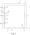
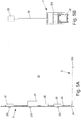
- Fig. 1 shows a schematic view of a building door 1, which has a pivotable about a pivot axis D to a door frame 11 door leaf 10 which can be moved between an open position and a closed position to the door leaf 10 to open the building door 1 in a known manner or close.
- a locking device 2 is arranged in the form of a multiple lock on the door 10, which serves to lock the door 10 in its closed position with the door frame 11.
- the locking device 2 has a first latch assembly 21 in the form of a door lock with a latch 210 and a plurality of latch assemblies 22 with locking elements 220, which together serve the door leaf 10 at different, on the outer circumference of the door leaf 10 staggered locations with the door frame eleventh to lock.
- a transmission element 23 in the form of a linkage which can be electrically adjusted by a drive device 20 in the form of an electric motor, the locking devices 21, 22 can be operated together to the locking elements 220 and the latch 210 together and synchronously to lock and unlock the Door leaf 10 to adjust.
- the locking device 2 can be moved by the electric motor via the drive device 20. Also conceivable and possible is a manual operation independent of the drive device 20 via a door handle 100.
- Locking devices 22 can not only be arranged on the closing edge of the door leaf 10 remote from the pivot axis D, but also on the upper edge and on the counter-closing edge of the door leaf 10 facing the pivot axis D.
- the building door 1 has a sealing unit 3 with a sealing assembly 30 adjustable in the direction of adjustment A in the form of a sealing strip, which seals a gap between the door leaf 10 and a bottom 4 on the underside of the door leaf 10 when the door leaf 10 is in the closed position.
- the seal assembly 10 is in this case in the adjustment direction A relative to the door 10 extendable to close the gap in the closed position.
- the sealing assembly 30 can be retracted against the adjustment direction A in the door leaf 10, to allow in this way an unhindered movement of the door leaf 10 to the door frame 11.
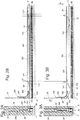
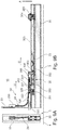
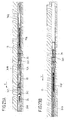
- Figs. 2A, 2B and 3A, 3B show an embodiment of a sealing unit 3 on the door leaf 10 in the retracted position of the seal assembly 30 (FIG. Fig. 2A, 2B ) and in the extended position of the seal assembly 30 (FIG. Fig. 3A, 3B ).
- the sealing unit 3 has a housing 323 and, in this embodiment, two spring elements 31 formed by torsion springs, via which the seal assembly 30 in the form of a along the lower edge of the door leaf 10 extended sealing element is resiliently adjustable.
- the sealing unit 3 has no own (motor) drive, but is adjusted via the locking device 2.
- the transmission element 23 is coupled in the form of the linkage of the locking device 2 via a coupling device 24 in the form of, for example, a Bowden cable with the sealing unit 3 by a guided in a coupling guide 240, flexible power transmission element 241 of the coupling device 24 on pushers 311, each with a Spring end 315 of the spring elements 31 are coupled, attacks and can be adjusted to move the pushers 311.
- the coupling guide 240 is at one of the sealing unit 3 associated end via a support member 242 on the housing 323 of the sealing unit 3 and also at its other end via a stationary to the door 10 arranged (not shown in detail) Bowdenrohrabstützung against the door 10th supported.
- the force transmission element 241 of the coupling device 24 is fixed via a coupling element 230 to the transmission element 23 in the form of the linkage, so that by adjusting the transmission element 23, the force transmission element 241 of the coupling device 24 moves relative to the coupling guide 240 and thereby the pushers 311 can be adjusted.
- the spring elements 31 are each connected to a spring end 315 with an associated thrust element 311 and fixed to a different spring end 314 via a respective fastening element 310 on the housing 323 of the sealing unit 3.
- the spring ends 314, 315 can be changed in position relative to each other, in order in this way the seal assembly 30 between the retracted position ( Fig. 2A, 2B ) and the extended position ( Fig. 3A, 3B ) to move.
- the thrust elements 311 are offset by a distance X, as is clear from the transition from Fig. 2B towards Fig. 3B it can be seen to in this way to pivot the spring ends 314, 315 (under tension of the spring elements 31) to each other and thereby the seal assembly 30 from the retracted position to the extended position to convict.
- the seal assembly 30 protrudes outwardly from the housing 323 of the sealing unit 3 and seals a gap between the door leaf 10 and a bottom 4 on the underside of the door leaf 10, as in particular Fig. 3A is apparent.
- the adjustment of the locking device 2 and the sealing unit 3 takes place in a synchronous manner.
- the locking device 2 is driven to lock the door leaf 10 with the door frame 11 and to the transmission element 23 adjusted in the direction of movement V, as is apparent from Fig. 3B is apparent.
- the seal assembly 30 is extended synchronously and thus the door leaf 10 is sealed relative to the bottom 4.
- the locking device 2 is unlocked by adjusting the transmission element 23 against the direction of movement V, whereby the seal assembly 30 is lifted off the base 4 and placed back in the retracted position.
- the seal assembly 30 In the closed position, the seal assembly 30 is under spring bias of the spring elements 31 on the bottom 4. This allows a tolerance compensation and a compensation of unevenness in the bottom 4. In addition, a readjustment of the sealing unit 3 is not required or at least considerably simplified.
- the movement of the seal assembly 30 can be effected directly by adjusting the transmission element 23 of the locking device 2, as described above with reference to the embodiment according to FIG Figs. 2A, 2B and 3A, 3B explained.
- a tensile force is transmitted via the power transmission element 241 of the coupling device 24 and introduced into the pushers 311, which are thereby displaced by a distance X and the Lower the seal assembly 30 via the spring elements 31.
- the force transmission element 241 is reset against the direction of movement V, so that the seal assembly 30 is lifted due to the spring action of the spring elements 31 again.
- the lowering of the seal assembly 30 to the extended position is independent of the locking means 2, while the lifting for transferring the seal assembly 30 to the retracted position is effected by the locking means 2.
- the seal assembly 30 is supported via a (at least) a spring element 31 on a housing 323 of the sealing unit 3, wherein a spring arm 314 with a fixing element fixedly fixed to the housing 323 and the other spring arm 315 of the spring element 31 formed as a leg spring on a push element 311, which is guided transversely to the adjustment direction A of the seal assembly 30 slidably mounted on the housing 3, is attached.
- the thrust element 311 is in this case supported by a damping element 33 on the housing 323 and thus displaced in a damped manner to the housing 323.
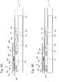
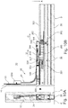
- the sealing unit 3 of the embodiment according to Figs. 4A-4D to 6A-6D has a locking assembly 32 which serves to move the pusher 311 and above the seal assembly 30 in the retracted position (FIG. Fig. 4A ) to lock relative to the housing 323 and thus to hold in the retracted position.
- the locking assembly 32 has for this purpose a blocking element 327 in the form of a pivotable about a pivot axis 328 locking lever which is in the retracted position of the seal assembly 30 latchingly engaged with the associated thrust element 311 and thus holds this in position relative to the housing 323, as out Fig. 4A is apparent.
- the blocking assembly 32 has a pressure element 320 with a shaft 321, which is spring-biased via a spring element 322 in the form of a compression spring to a housing portion 324 of the housing 323 and is connected to a trigger element 326.
- the pressure element 320 is, in a normal position, held by the collar 325 fixedly connected between the housing section 324 and a shaft 321 acting spring element 322, out of the housing 323 at the closing edge of the door leaf 10 outwardly, as for example Fig. 5B is visible, and serves to interact when closing the door leaf 10 with the frame 11 (in particular a frame edge 110 which is opposite the closing edge of the door leaf 10 when the door leaf 10 is closed).
- the pressure element 320 runs when closing the door leaf 10 on the frame edge 110, as in the transition from Fig. 5D in addition Fig. 6D is apparent, and is thereby pressed in an unlocking direction U against the spring force of the spring element 322 in the housing 323.
- the trigger element 326 is moved in the unlocking direction U and acts on the blocking element 327 such that the blocking element 327 is pivoted about the pivot axis 328 and disengaged from the pusher element 311, as can be seen from the sequence of FIGS Fig. 4A towards Fig. 4D is apparent.
- the seal assembly 30 moves automatically due to the spring force of the (biased in the retracted position) spring member 31 in the adjustment direction A down to the bottom 4 and is thus transferred to the extended position.
- the lowering of the seal assembly 30 takes place here due to the damping element 33, for example formed as a gas spring, in a damped manner.
- the lowering of the seal assembly 30 is thus not sudden, but delayed in time, which prevents grinding of the seal assembly 30 on the ground before reaching the fully closed position of the door leaf 10.
- the spring element 31 is coupled in the illustrated embodiment via a slider 312 centered on the spring element 31 with the seal assembly 30 and slidably guided on a sliding guide 313 of the seal assembly 30.
- the slider 312 moves transversely to the adjustment direction A on the slide 313 and thereby compensates for a transverse movement of the pusher 311 when lowering the seal assembly 30 from.
- the lowering of the seal assembly 30 is carried out in this embodiment, thus by interaction of the locking assembly 32 with the door frame 11 and thus basically independent of the locking device 2.
- the lowering takes place here when closing the door leaf 10 immediately upon reaching the closed position.
- the locking device 2 In the closed position of the door leaf 10, the locking device 2 is in the locking position and thus locks the door leaf 10 via the locking assemblies 22 and the door lock 21 with the door frame 11, as shown for example in FIG Fig. 6A is shown. If the door leaf 10 is to be opened again, then the locking device 2 is actuated by adjusting the transmission element 23 for unlocking the latch assemblies 22 and the door lock 21, wherein via a coupling device 24 in the form of, for example, a Bowden cable movement of the transmission element 23 also retracting the pusher element 311 in a direction of release U opposite direction of movement B (see Fig. 6C ) causes. Above this, the seal assembly 30 is pulled back to the retracted position, in which the locking member 327 in turn is latched to the pusher 311, as shown in FIG Fig. 4A and 5A to 5D is shown.
- the seal assembly 30 is returned to the retracted position and thus raised.
- the transmission element 23 is driven in the form of the linkage driven by the drive device 20 in such a position that upon renewed closing of the door leaf 10 and upon release of the locking element 327, the seal assembly can be extended again.
- a spring element 31 In the embodiment according to Figs. 4A-4D to 6A-6D only one spring element 31 is shown. However, there may also be two (or more) spring elements 31, each connected to a fastener 310 and a pusher 311, it being generally sufficient to provide a (single) pawl assembly 32 for latching one of the pushers 311.
- Figs. 7A-7C and 8A-8C illustrated embodiment is substantially functionally identical to the embodiment according to Figs. 4A-4D to 6A-6D ,
- a locking assembly 32 is provided which holds the seal assembly 30 in the retracted position (FIG. Figs. 7A to 7C ) and can be triggered by interaction of a pressure element 320 with the door frame 11 to a blocking element 327 to a Swivel pivot axis 328 and thereby release a thrust element 311. Due to the spring action (at least) of a spring element 31, the seal assembly 30 is thereby lowered in a damped manner via a damping element 33.
- the pressure element 320 is spring-biased via a spring element 322 relative to the trigger element 326, and also the trigger element 326 is spring-biased via a spring element 329 relative to the housing 323.
- the pressure element 320 initially acts elastically on the spring element 322 and then block via a shaft 321 on the trigger element 326 and adjusts this in the release direction U to trigger the locking element 327, as in the transition from Fig. 7C towards Fig. 8C is apparent.
- the force transmission element 241 of the coupling device 24 is fixed to a coupling element 243 and connected to the thrust element 311, so that the force transmission element 241 acts on the thrust element 311 when the sealing assembly 30 is reset in the retracted position.
- sealing unit 3 is coupled to the locking device 2 via the coupling device 24, a separate (electromotive) drive on the sealing unit 3 can be dispensed with.
- the adjustment in at least one direction of movement via the drive 20 of the locking device 2, so that the sealing unit 3 is actuated in response to an actuation of the locking device 2.
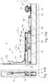
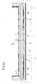
- an adjusting mechanism 35 for adjusting the seal assembly 30 is provided, which is designed as a pinion gear.
- racks 354 extending along the adjustment direction A are fixedly connected to the seal assembly 30 and are engaged with pinions 353 rotatably mounted on the housing 323 of the seal unit 3.
- the pinions 353 are operatively connected to a drive linkage 350 in that the pinions 353 are engaged with toothed sections of the drive linkage 350 such that upon movement of the drive linkage 352 along a direction of movement C directed transversely to the adjustment direction A, the pinions 353 are rotated (synchronously) and above Racks 354 for lowering or raising the seal assembly 30 are driven.
- two racks 354 along the direction of movement C are arranged offset to each other on the seal assembly 30 and are engaged with two associated pinions 353. Forces are thus introduced into the seal assembly 30 at spaced-apart locations.
- the drive linkage 352 is connected to a carriage 350, which is spring-biased via a spring element 351 relative to the housing. Via the carriage 350, the drive linkage 352 for lowering the seal assembly 30 (in the direction of the extended position) in the direction of movement C and for lifting the seal assembly 30 (in the retracted position) against the direction of movement C is movable.
- the sealing unit 3 also has a locking assembly 32 which corresponds to the locking assembly 32 of the embodiment Figs. 7A to 7C and 8A to 8C functionally equivalent.
- the seal assembly 30 When the door leaf 10 is open, the seal assembly 30 is in its retracted position according to Figs. 9A, 9B , In this retracted position, the carriage 350 and above the drive linkage 352 is held in position via a lock lever 327 of the lock assembly 32, as shown in FIG Fig. 9B is shown, so that above the seal assembly 30 is locked in its retracted position.
- a pressure element 320 of the locking assembly 32 cooperates with an edge of the door frame 11 and is thereby pressed in an unlocking U in the door leaf 10, whereby a trigger element 326 acts on the pivotable about a pivot axis 328 to the housing 323 locking lever 321 and disengages it from the carriage 350 of the adjustment mechanism 35.
- the locking assembly 32 is thus triggered and the seal assembly 30 released, so that the seal assembly 30, due to the spring bias of the carriage 350 relative to the housing 323, via the meshing with the racks 354 pinion 353 is automatically adjusted to the extended position, as soon as the door leaf 10 is closed.
- the movement of the drive linkage 152 is attenuated here via a damping spring 33 in the form of a gas spring or the like, so that the lowering is not abrupt, but in time (slightly) delayed manner.
- the coupling device 24 acts on a coupling element 243 in the form of a driver, which interacts with the carriage 350 and moves it counter to the direction of movement C.
- the drive linkage 352 is also moved, whereby the pinion 353 is driven and thereby the seal assembly 30 is raised (in Fig. 10B only one pinion 353 is shown, the other is omitted for the sake of clarity).
- the coupling element 243 is in this case via a Spring element 244 biased relative to the housing 323 of the sealing unit 3, so that the return of the coupling element 243 (in the direction of movement C) takes place in spring-assisted manner.
- the seal assembly 30 is raised directly and in coupled manner with the locking device 2, a grinding of the seal assembly 30 at the bottom 4 is avoided.
- the seal assembly 30 is lowered in the direction of the bottom 4 only when the door leaf 10 has reached its closed position, and is immediately raised again when the door leaf 10 is unlocked to open.
- FIG. 11A, 11B and 12A, 12B Functionally corresponds essentially with the embodiment according to Figs. 9A, 9B and 10A, 10B ,
- a damping spring 33 is provided for biasing the carriage 350 relative to the housing.
- the drive linkage 352 is not continuous, but divided into two linkage sections which are interconnected via a linkage 356 for joint movement.
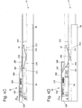
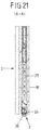
- FIGS. 13 and 14 show schematic views of an embodiment in which a power transmission for adjusting the seal assembly 30 via a link element 36 takes place that is associated with the illustrated embodiment, the seal assembly 30 and is driven directly via the coupling device 24.
- the link element 36 is elastically resiliently connected to the seal assembly 30 via a spring support 361 along the adjustment direction A, so that the seal assembly 30 (slightly) along the adjustment direction A relative to the link element 36 can be adjusted.
- the link element 36 has an oblique to the adjustment direction A extending link 360 into which an engagement member 245 engages in the form of a pin, which is displaceable on a along a direction of movement C on a housing 323 of the sealing unit 3 and arranged above the door leaf 10 coupling element 243 is arranged.
- the coupling element 243 is connected to the force transmission element 241 of the coupling device 24 in connection that the coupling element 243 is moved in a movement of the force transmission element 241 along the direction of movement C.
- the seal assembly 30 is driven both in the adjustment direction A for lowering the seal assembly 30 in the extended position and against the adjustment direction A for retracting the seal assembly 30 in the retracted position via the coupling device 24.
- the force transmission element 241 of the coupling device 24 is moved along the direction of movement C, moved over the coupling element 243 and thereby, due to the link coupling between the coupling element 243 and the link element 36, the seal assembly 30 moved between their different positions.
- the seal assembly 30 is lowered when the coupling element 243 against the direction of movement C from the position according to Fig. 13 in the position according to Fig. 14 is moved. Is, driven by the coupling device 24, the coupling element 243 reversed in the direction of movement C from the position according to Fig. 14 in the position according to Fig. 13 transferred, the seal assembly 30 is retracted.
- the seal assembly 30 is preferably at the bottom 4, wherein due to the spring support 361 between the link element 36 and the seal assembly 30, a positional match between the link element 36 and the seal assembly 30 is possible, thus unevenness in the bottom 4 can be compensated and a Tension in the system is avoided.
- the coupling device 24 may be designed in the manner of a Bowden cable with a guided in a Bowden tube soul. It is also conceivable and possible, as shown schematically in FIGS. 15 and 16 is shown to form the coupling device 24 in the manner of a so-called corner deflection, in which the force transmission element 241 is guided in the form of a flexible, for example made of spring steel strip in a coupling guide 240, as for example in Fig. 16 is shown.
- the power transmission element 241 can be moved within the coupling guide 240, wherein the force transmission element 241 is firmly connected on the one hand with transmission element 23 of the locking device 2 and on the other hand firmly with the coupling element 243 on the part of the sealing unit 3, so that the coupling element 243 via the force transmission element 241 together with the transmission element 23 of the locking device 2 is moved.
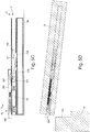
- Figs. 16 to 24A-24C show a further embodiment of a sealing unit 3, which has a seal assembly 30 and is disposed on a lower edge of a door leaf 10 for sealing against a floor.
- the sealing unit 3 is operatively connected to a locking device 2 in the form of a multiple locking, analogous to the above with reference to Fig. 1 has been described.
- the locking device 2 in the form of multiple locking bolt assemblies 22 which can be adjusted together via a transmission element 23 in the form of a linkage to effect a lock between the door 10 and a frame 11 at a plurality of locations when the locking device 2 in a locked position.
- the laying device 2 is operatively connected via a coupling device 24 with the sealing unit 3.
- the coupling device 24 is formed in the illustrated embodiment as a Bowden cable and serves to initiate an adjusting force of the locking device 2 in the sealing unit 3, to effect an adjustment of the seal assembly 30 of the sealing unit 3 between different positions.
- the coupling device 24 may for example also be formed by a corner deflection or by another coupling.
- Figs. 18 to 24A-24C how out Figs. 18 to 24A-24C can be seen, the sealing unit 32 on link elements 36 which are fixedly connected to the adjustable along an adjustment A seal assembly 30 of the sealing unit 3 and a force deflection for adjusting the seal assembly 30 between an extended position ( Fig. 18 ) and a retracted position ( Fig. 19 and 20 ) cause.
- the coupling device 24 in the form of the Bowden cable on a coupling guide in the form of a Bowden sleeve 240 which is supported at the sealing unit 3 associated end within a housing 323 on a support member 242, as in particular Fig. 22 and Fig. 23A is apparent.
- a power transmission element 241 is guided in the form of a soul of the Bowden cable and connected on the part of the sealing unit 3 with a damping element 33, which is formed in the illustrated embodiment, for example as a gas spring or as an oil damper.
- each engagement element 245 is fixedly connected to an associated connection element 34A, 34B in the form of the respective linkage and can be moved by moving the connection element 34A, 34B relative to the respective link element 36.
- each linkage 34A, 34B is spring-biased relative to the housing 323 via an associated spring element 37A, 37B, such that adjustment of the connection elements 34A, 34B in an adjustment direction V for lifting the seal assembly 30 from an extended position (FIG. Fig. 18 ) into a retracted position ( Fig. 19 . 20 ) takes place against the spring bias of the spring elements 37A, 37B.
- each engagement element 245 is in the extended position of the seal assembly 30 in an upper position in a link 360 of the respective link element 36, as is apparent from Fig. 24A is apparent.
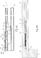
- the associated linkage 34A, 34B moved in the adjustment direction V (driven by the locking device 2)
- the engagement member 245 is displaced in the link 360, wherein the engagement member 245 is moved linearly along the adjustment direction V together with the associated connecting element 34A, 34B
- the link element 36 is raised in a stroke direction H, wherein in a further adjustment of the locking device 2, the engagement member 245 can perform a free stroke in the backdrop 360, as in the transition from Fig. 24B towards Fig. 24C (corresponding to the transition from Fig. 19 towards Fig. 20 ) can be seen.
- the seal assembly 30 is lifted in the lifting direction H and thus from the extended position (FIG. Fig. 18 ) in the retracted position ( Fig. 19 . 20 ) adjusted. This occurs when the locking device 2 is adjusted to lock the door leaf 10 to the door frame 11.
- the sealing unit 3 automatically resets itself due to the spring forces of the pretensioned spring elements 37A, 37B, so that the seal assembly 30 is once again extended and comes into abutment with a floor located below the door leaf 10 (corresponding to the extended position according to FIG Fig. 17 ).
- the sealing unit 3 is coupled to a locking device 2 in the form of a turn-tilt hardware such as a patio door or the like.
- a locking device 2 in the form of a turn-tilt hardware such as a patio door or the like.
- a turn-tilt fitting By means of such a turn-tilt fitting, a building door in a pivoting position of Locking device 2 is pivoted about a vertical pivot axis and tilted in a tilted position of the locking device 2 about a horizontal tilt axis, so that the door leaf 10 can be brought into a tilted position.
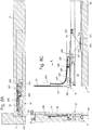
- the locking device 2 is coupled via a circumferentially on the door leaf 10 rotating linkage 23 with the sealing unit 3, as shown in the sectional view Fig. 28 is apparent.
- the linkage 23 carries locking pins which can be engaged or disengaged by adjusting the linkage 23 with associated strikers on the side of the door frame to pivot the door leaf 10 about a vertical pivot axis and in the tilted position of the locking device in the pivoted position of the locking device 2 2 tilting of the door leaf 10 to allow the horizontal tilt axis.
- the coupling of the linkage 23 of the locking device 2 with the sealing unit 3 takes place in the illustrated embodiment via a coupling device 24 in the form of a driver, the-like Fig. 28 seen - is connected via a fastener 246 fixed to the power transmission element in the form of the linkage 23 of the locking device 2, so that the driver 24 is movable together with the linkage 23.
- adjustment mechanisms in the form of lever mechanism 39 are adjusted via the coupling device 24 in the form of the driver, in order thereby to move the seal assembly 30 of the sealing unit 3 between an extended position (FIG. Fig. 25 ) and a retracted position ( Fig. 26, 27 ) to move.
- the coupling means 24 is coupled in the form of the driver via a first spring element 38 A with a linkage 34.
- An active connection with the two adjusting mechanisms in the form of the lever mechanism 39 is produced via the linkage 34, so that the lever mechanism 39 is actuated by adjusting the linkage 34 and thereby the seal assembly 30 can be adjusted.
- the spring elements 38A, 38B are largely relieved.
- the seal assembly 30 is held in the extended position via the lever mechanism 39 and is pressed into contact with a floor below a lower frame edge 110 of the door frame 11.
- each lever mechanism 39 has a lever member 390 which is pivotally connected to the seal assembly 30 with a lever end 392.
- the lever member 390 is also pivotally connected to a lever 391 which is pivotally connected to a lever end 394, but stationary with the housing 323 of the sealing unit 3.
- the lever element 390 also has on a lever element 390 facing away from the end a coupling pin 393, via which the lever member 390 is coupled to a link engagement 340 of the connecting element 34 in the form of the linkage, so that a tensile force in the adjustment direction V on the connecting element 34 in the form of Linkage leads to an adjustment of the lever member 390.
- the second spring element 38B is tensioned, so that a prestressing with respect to the housing 323 is effected.
- the seal assembly 30 is already retracted. If the locking device 2 is further adjusted, for example, to the locking device 2 from its pivotal position (in which a pivoting of the door leaf 10 about the vertical pivot axis is possible) in a tilted position (in which a tilting of the door leaf 10 about the horizontal tilt axis is possible) cause such an adjustment of the locking device 2 by moving the coupling device 24 in the form of the driver, without the seal assembly 30 is moved further in the stroke direction H. Such a movement of the coupling device 24 causes a further tensioning of the spring element 38 to train, so that due to the elasticity of the spring element 38A, a further adjustment movement of the locking device 2 is compensated.
- the sealing unit 3 In a reverse adjustment of the locking device 2 and thus also the coupling device 24 in the form of the driver, the sealing unit 3 automatically returns, so that the seal assembly 30 automatically, due to the spring forces of the spring elements 38A, 38B, in the extended position ( Fig. 25 ) is lowered.
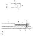
- a locking device 2 in the form of a multiple locking with bolt assemblies 21, 22 is provided, wherein an electromotive drive means 20 is arranged in the form of a spindle drive directly to a power transmission element 23 in the form of a linkage of the locking device 2.
- the drive device 20 is in this case integrated in a profile part of the door leaf 10, as is made Fig. 31 is apparent.
- the building door 1 has an adjusting drive 12, which is integrated horizontally into an upper section of the door leaf 10 and serves to electromotive adjustment of the door leaf 10 between a closed position and an open position.
- Both the adjusting drive 12, which acts on a secondary closing edge of the door frame 11, and the drive device 20 of the locking device 2 are connected to a control device 13, which serves to control the operation of the adjustment 12 and the locking device 2.
- the power transmission element 23 can be adjusted by electric motor in the form of the linkage of the locking device 2, so that synchronously the bolt assemblies 21, 22 of the locking device 2 can be moved. Due to a coupling via a coupling device 24, for example in the form of a Bowden cable or a corner drive, an adjustment of a seal assembly of a tightness 3 can also take place.
- the drive device 20 is designed as a spindle drive, which - as in Fig. 32 illustrated - an electric motor driven spindle 201 and having a spindle 200 in threaded engagement with the spindle nut 201.
- the spindle nut 201 can be moved longitudinally along the spindle 200 to thereby move the rod 23 coupled to the spindle nut 201 linearly to the door leaf 10.
- the spindle nut 201 is connected to a closing element 202, which serves as a closing aid.
- a guideway 103 is formed, which may be curved (as in the illustrated embodiment) or alternatively may be formed as an inclined plane and with a pin member 111 on the side of the door frame 11 cooperates to assist in closing the door leaf 10 in the last phase of the closing movement of Door leaf 10 provide.
- the pin member 111 on the door frame 11 - immediately before the door leaf 10 is fully closed - in engagement with the guide track 203 of the closing element 202.
- the pin member 111 be brought into engagement with the closing element 202 and thereby the door leaf 10 are pulled towards the door frame 11, so that a final path for retracting the door leaf 10 in the door frame 11 can be supported by the electric drive motor 20.
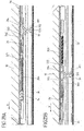
- Figs. 34A, 34B and 35A, 35B show a further embodiment of a sealing unit 3, the functionally largely the embodiment according to Fig. 25-29 corresponds, so that reference should also be made to the above.
- a seal assembly 30 is connected to a lever member 390 of a lever mechanism 39 and via the lever mechanism 39 between a retracted position ( Fig. 34B ) and an extended position ( Fig. 34A ) adjustable.
- a connecting element 34 is biased in the form of a linkage via a spring element 38C in the form of a compression spring against a fixedly connected to the housing 323 of the seal 3 housing portion in that the spring element 38C between the housing portion 323B and one fixed to the connecting element 34th connected carrier portion 344 is supported and is tensioned in an adjustment of the connecting element 34 in an adjustment direction V on pressure.
- the spring element 38C is tensioned so that the seal assembly 30 can be returned toward the extended position assisted by the biasing spring force of the spring element 38C (thus, in the embodiment, a spring element 38B at the other end of the connection element 34 may be used the embodiment according to Fig. 25-29 be waived).
- Another spring 38D is provided between portions of the connecting member 34 and serves for elastic clearance compensation.
- the connecting element 34 is according to the embodiment Figs. 34A, 34B and 35A, 35B connected to a coupling piece 341 in the form of a locking element, which serves for producing a releasable coupling with the coupling device 24.
- the coupling piece 341 has a latching head 342 arranged on a limb 346 for latching with a latching opening 323A on the housing 323, which is elastically adjustable and connected to an actuating section 343 in the form of a tension spring, so that actuation of the actuating section 343 effects an adjustment of the latching head 342 can be.
- a form-fitting element 345 is formed, which serves for producing the coupling with a coupling element 243 of the coupling device 24.
- the coupling device 24 is coupled to the coupling piece 341 and above with the connecting element 34 of the sealing unit 3. This is effected in that the locking head 342 is in abutment with a surface of the housing 323 and the leg 346 carrying the locking head 342 is elastically displaced inwardly toward another, opposite leg 347 of the coupling piece 341, so that a positive connection between the coupling element 243 the coupling device 24 and the interlocking element 345 of the coupling piece 341 is made, as is apparent from Fig. 35A is apparent.
- the coupling piece 341 is thus moved together with the coupling device 24 and the seal assembly 30 thus retracted.
- the sealing unit 3 Due to the latching via the coupling piece 341, the sealing unit 3 is held in this position, whereby the fact that the leg 346 is removed from the opposite leg 347 and thus the positive-locking element 345 is displaced outwards releases the positive connection between the coupling device 24 and the coupling piece 341 is and the coupling device 24 can be adjusted independently of the sealing unit 3 in the adjustment direction V.
- the with the Coupling device 24 connected locking device 2 can thus be adjusted independently of the sealing unit 3, for example, to achieve an unlocked position or to move the locking device 2 between different unlocked positions (for example, a pivotal position and a tilted position).
- the coupling device 24 moves with the coupling element 143 into the receptacle formed between the legs 346, 347 and reaches the actuating section 343
- Form of the tension spring in interaction which causes the locking head 342 lifted from the locking opening 323A of the housing 323 and the latch is thus canceled.
- the seal assembly 30 is thus no longer held in the retracted position.
- the seal assembly 30 can thus be extended by movement of the locking device 2 against the adjustment direction V and supported by the biasing spring action of the tensioned in the retracted position spring 38C again.
- An assembly of the type described above can be used in very different building doors, for example, interior doors or exterior doors.
- An assembly of the type described here can be used not only for sealing a door leaf relative to the floor, but also, for example, for sealing against the door frame.
Landscapes
- Engineering & Computer Science (AREA)
- Civil Engineering (AREA)
- Structural Engineering (AREA)
- Mechanical Engineering (AREA)
- Specific Sealing Or Ventilating Devices For Doors And Windows (AREA)
Applications Claiming Priority (1)
| Application Number | Priority Date | Filing Date | Title |
|---|---|---|---|
| DE102018204075.3A DE102018204075A1 (de) | 2018-03-16 | 2018-03-16 | Dichteinheit für eine Gebäudetür |
Publications (3)
| Publication Number | Publication Date |
|---|---|
| EP3550102A2 true EP3550102A2 (fr) | 2019-10-09 |
| EP3550102A3 EP3550102A3 (fr) | 2020-01-22 |
| EP3550102B1 EP3550102B1 (fr) | 2021-11-24 |
Family
ID=65818380
Family Applications (1)
| Application Number | Title | Priority Date | Filing Date |
|---|---|---|---|
| EP19163547.3A Active EP3550102B1 (fr) | 2018-03-16 | 2019-03-18 | Assemblage pour une porte de bâtiment avec une unité d'étanchéité et un dispositif de verrouillage |
Country Status (2)
| Country | Link |
|---|---|
| EP (1) | EP3550102B1 (fr) |
| DE (1) | DE102018204075A1 (fr) |
Cited By (3)
| Publication number | Priority date | Publication date | Assignee | Title |
|---|---|---|---|---|
| CN113404419A (zh) * | 2020-03-17 | 2021-09-17 | Ykk Ap 株式会社 | 门窗用附件装置及门窗 |
| CN120193733A (zh) * | 2025-05-13 | 2025-06-24 | 步阳集团有限公司 | 一种偏轴门 |
| CN121088282A (zh) * | 2025-11-11 | 2025-12-09 | 山西启迪信科技有限公司 | 一种用于无门槛式人防门的密封结构 |
Families Citing this family (1)
| Publication number | Priority date | Publication date | Assignee | Title |
|---|---|---|---|---|
| CN114391057B (zh) * | 2019-09-13 | 2023-09-12 | 多玛卡巴美国公司 | 管状出口装置以及安装方法 |
Citations (4)
| Publication number | Priority date | Publication date | Assignee | Title |
|---|---|---|---|---|
| DE29722616U1 (de) | 1997-12-20 | 1998-02-26 | Hohnholt Trennwandideen, 36157 Ebersburg | Wandelement mit Durchgangstür für bewegliche Trennwände |
| EP1772586A2 (fr) | 2005-10-05 | 2007-04-11 | Firma F. Athmer | Joint d'étanchéité, méthode et dispositif pour installer ces joints, port comportant ces joints |
| DE202013100864U1 (de) | 2013-02-28 | 2013-06-03 | Claudia Rager-Frey | Bodenschiene |
| DE102014106702A1 (de) | 2014-05-13 | 2015-11-19 | Athmer Ohg | Türdichtungssystem |
Family Cites Families (8)
| Publication number | Priority date | Publication date | Assignee | Title |
|---|---|---|---|---|
| US974959A (en) * | 1909-06-03 | 1910-11-08 | Georg Goette | Draft-excluder for doors. |
| CH166123A (de) * | 1933-02-18 | 1933-12-31 | Blaser & Soehne A | Abdichteinrichtung an Türen und ähnlichen Abschlussorganen. |
| US2765504A (en) * | 1950-02-06 | 1956-10-09 | Laumann Joseph | Draught excluders for doorways |
| FR2712346A1 (fr) * | 1993-11-09 | 1995-05-19 | Poulitou Christian | Dispositif d'étanchéité pour porte ou similaire à éléments composés magnétiques. |
| DE29720978U1 (de) * | 1997-11-26 | 1998-03-12 | Ernst Keller GmbH & Co KG, 59757 Arnsberg | Vorrichtung zum Arretieren von Türen in beliebigen Schwenkwinkeln |
| DE202007016428U1 (de) * | 2007-11-22 | 2008-02-14 | F. Athmer Ohg | Dichtung mit einer absenkbaren Dichtungsleiste und mindestens einem Auslöseelement |
| EP3212875B1 (fr) * | 2014-10-27 | 2020-11-25 | ASSA ABLOY (Schweiz) AG | Dispositif d'étanchéité |
| DE102017112906A1 (de) * | 2017-06-12 | 2018-12-13 | Pax Ag | Tür |
-
2018
- 2018-03-16 DE DE102018204075.3A patent/DE102018204075A1/de not_active Withdrawn
-
2019
- 2019-03-18 EP EP19163547.3A patent/EP3550102B1/fr active Active
Patent Citations (4)
| Publication number | Priority date | Publication date | Assignee | Title |
|---|---|---|---|---|
| DE29722616U1 (de) | 1997-12-20 | 1998-02-26 | Hohnholt Trennwandideen, 36157 Ebersburg | Wandelement mit Durchgangstür für bewegliche Trennwände |
| EP1772586A2 (fr) | 2005-10-05 | 2007-04-11 | Firma F. Athmer | Joint d'étanchéité, méthode et dispositif pour installer ces joints, port comportant ces joints |
| DE202013100864U1 (de) | 2013-02-28 | 2013-06-03 | Claudia Rager-Frey | Bodenschiene |
| DE102014106702A1 (de) | 2014-05-13 | 2015-11-19 | Athmer Ohg | Türdichtungssystem |
Cited By (6)
| Publication number | Priority date | Publication date | Assignee | Title |
|---|---|---|---|---|
| CN113404419A (zh) * | 2020-03-17 | 2021-09-17 | Ykk Ap 株式会社 | 门窗用附件装置及门窗 |
| EP3882423A1 (fr) * | 2020-03-17 | 2021-09-22 | YKK AP Inc. | Dispositif de fixation pour ouvrant et ouvrant |
| CN113404419B (zh) * | 2020-03-17 | 2023-08-29 | Ykk Ap 株式会社 | 门窗用附件装置及门窗 |
| CN120193733A (zh) * | 2025-05-13 | 2025-06-24 | 步阳集团有限公司 | 一种偏轴门 |
| CN121088282A (zh) * | 2025-11-11 | 2025-12-09 | 山西启迪信科技有限公司 | 一种用于无门槛式人防门的密封结构 |
| CN121088282B (zh) * | 2025-11-11 | 2026-02-03 | 山西启迪信科技有限公司 | 一种用于无门槛式人防门的密封结构 |
Also Published As
| Publication number | Publication date |
|---|---|
| DE102018204075A1 (de) | 2019-09-19 |
| EP3550102B1 (fr) | 2021-11-24 |
| EP3550102A3 (fr) | 2020-01-22 |
Similar Documents
| Publication | Publication Date | Title |
|---|---|---|
| DE102011006524B4 (de) | Tür oder Fenster eines Gebäudes mit einer motorischen Antriebsvorrichtung | |
| EP3550102B1 (fr) | Assemblage pour une porte de bâtiment avec une unité d'étanchéité et un dispositif de verrouillage | |
| DE102016104778B4 (de) | Türantrieb mit Haupt- und Hilfsantrieb | |
| EP1370742A1 (fr) | Structure de fenetre ou de porte | |
| EP0119433B2 (fr) | Ferrure pour un panneau de fenêtre, de porte ou similaire, pouvant au moins basculer et se déplacer d'un plan dans un deuxième plan parallèle | |
| EP1307626A1 (fr) | Systeme de fermeture pour porte de vehicule | |
| DE68903724T2 (de) | Beschlag fuer tuer, fenster oder dergleichen. | |
| EP3406832B1 (fr) | Gâche pour une serrure antipanique | |
| DE9104553U1 (de) | Mehrriegel-Türschloß | |
| DE19516588C1 (de) | Feststellvorrichtung für Fenster, Türen od. dgl. | |
| DE19902150A1 (de) | Ausstellvorrichtung für einen an einem Rahmen schwenkbar angebrachten Kipp- oder Dreh-Kipp-Flügel | |
| DE102010005261B4 (de) | Schloss für eine Schienenfahrzeugtür | |
| WO2023143824A1 (fr) | Dispositif de décalage pour le décalage forcé d'un vantail, en particulier d'un vantail coulissant, d'une fenêtre ou d'une porte | |
| DE102015000606A1 (de) | Verriegelungsvorrichtung für einen schwenkbar gelagerten Flügel | |
| EP2202375A2 (fr) | Porte coulissante | |
| DE102013215716B4 (de) | Klappeneinrichtung eines Gebäudes | |
| EP4265878B1 (fr) | Agencement de porte | |
| EP3415706B1 (fr) | Porte | |
| EP1414689B1 (fr) | Véhicule ferroviaire avec une paroi coulissante et un système de verrouillage en partie basse de la paroi | |
| DE19832356C2 (de) | Kantenriegelbeschlag | |
| EP4421285B1 (fr) | Porte coulissante avec un battant coulissant verrouillable | |
| EP4441320B1 (fr) | Fenêtre ou porte | |
| DE102023122564A1 (de) | Gegenkasten für einen Standflügelverschluss | |
| DE10005884A1 (de) | Treibstangenbeschlag | |
| EP1746235A2 (fr) | Ensemble de ferrure |
Legal Events
| Date | Code | Title | Description |
|---|---|---|---|
| PUAI | Public reference made under article 153(3) epc to a published international application that has entered the european phase |
Free format text: ORIGINAL CODE: 0009012 |
|
| STAA | Information on the status of an ep patent application or granted ep patent |
Free format text: STATUS: THE APPLICATION HAS BEEN PUBLISHED |
|
| AK | Designated contracting states |
Kind code of ref document: A2 Designated state(s): AL AT BE BG CH CY CZ DE DK EE ES FI FR GB GR HR HU IE IS IT LI LT LU LV MC MK MT NL NO PL PT RO RS SE SI SK SM TR |
|
| AX | Request for extension of the european patent |
Extension state: BA ME |
|
| RIC1 | Information provided on ipc code assigned before grant |
Ipc: E06B 7/20 20060101AFI20190912BHEP Ipc: E06B 7/215 20060101ALI20190912BHEP Ipc: E05B 9/00 20060101ALI20190912BHEP Ipc: E06B 7/21 20060101ALI20190912BHEP Ipc: E05C 9/00 20060101ALI20190912BHEP |
|
| PUAL | Search report despatched |
Free format text: ORIGINAL CODE: 0009013 |
|
| AK | Designated contracting states |
Kind code of ref document: A3 Designated state(s): AL AT BE BG CH CY CZ DE DK EE ES FI FR GB GR HR HU IE IS IT LI LT LU LV MC MK MT NL NO PL PT RO RS SE SI SK SM TR |
|
| AX | Request for extension of the european patent |
Extension state: BA ME |
|
| RIC1 | Information provided on ipc code assigned before grant |
Ipc: E06B 7/21 20060101ALI20191217BHEP Ipc: E06B 7/215 20060101ALI20191217BHEP Ipc: E05C 9/00 20060101ALI20191217BHEP Ipc: E06B 7/20 20060101AFI20191217BHEP Ipc: E05B 9/00 20060101ALI20191217BHEP |
|
| STAA | Information on the status of an ep patent application or granted ep patent |
Free format text: STATUS: REQUEST FOR EXAMINATION WAS MADE |
|
| 17P | Request for examination filed |
Effective date: 20200716 |
|
| RBV | Designated contracting states (corrected) |
Designated state(s): AL AT BE BG CH CY CZ DE DK EE ES FI FR GB GR HR HU IE IS IT LI LT LU LV MC MK MT NL NO PL PT RO RS SE SI SK SM TR |
|
| GRAP | Despatch of communication of intention to grant a patent |
Free format text: ORIGINAL CODE: EPIDOSNIGR1 |
|
| STAA | Information on the status of an ep patent application or granted ep patent |
Free format text: STATUS: GRANT OF PATENT IS INTENDED |
|
| RIC1 | Information provided on ipc code assigned before grant |
Ipc: E06B 7/20 20060101AFI20210621BHEP Ipc: E06B 7/21 20060101ALI20210621BHEP Ipc: E06B 7/215 20060101ALI20210621BHEP Ipc: E05C 9/06 20060101ALI20210621BHEP Ipc: E05C 9/18 20060101ALI20210621BHEP Ipc: E05B 47/00 20060101ALI20210621BHEP |
|
| INTG | Intention to grant announced |
Effective date: 20210705 |
|
| GRAS | Grant fee paid |
Free format text: ORIGINAL CODE: EPIDOSNIGR3 |
|
| GRAA | (expected) grant |
Free format text: ORIGINAL CODE: 0009210 |
|
| STAA | Information on the status of an ep patent application or granted ep patent |
Free format text: STATUS: THE PATENT HAS BEEN GRANTED |
|
| AK | Designated contracting states |
Kind code of ref document: B1 Designated state(s): AL AT BE BG CH CY CZ DE DK EE ES FI FR GB GR HR HU IE IS IT LI LT LU LV MC MK MT NL NO PL PT RO RS SE SI SK SM TR |
|
| RAP3 | Party data changed (applicant data changed or rights of an application transferred) |
Owner name: EDS ELECTRIC DRIVE SOLUTION GMBH & CO. KG |
|
| REG | Reference to a national code |
Ref country code: GB Ref legal event code: FG4D Free format text: NOT ENGLISH |
|
| REG | Reference to a national code |
Ref country code: DE Ref legal event code: R096 Ref document number: 502019002804 Country of ref document: DE |
|
| REG | Reference to a national code |
Ref country code: AT Ref legal event code: REF Ref document number: 1449997 Country of ref document: AT Kind code of ref document: T Effective date: 20211215 |
|
| REG | Reference to a national code |
Ref country code: IE Ref legal event code: FG4D Free format text: LANGUAGE OF EP DOCUMENT: GERMAN |
|
| REG | Reference to a national code |
Ref country code: LT Ref legal event code: MG9D |
|
| REG | Reference to a national code |
Ref country code: NL Ref legal event code: MP Effective date: 20211124 |
|
| PG25 | Lapsed in a contracting state [announced via postgrant information from national office to epo] |
Ref country code: RS Free format text: LAPSE BECAUSE OF FAILURE TO SUBMIT A TRANSLATION OF THE DESCRIPTION OR TO PAY THE FEE WITHIN THE PRESCRIBED TIME-LIMIT Effective date: 20211124 Ref country code: LT Free format text: LAPSE BECAUSE OF FAILURE TO SUBMIT A TRANSLATION OF THE DESCRIPTION OR TO PAY THE FEE WITHIN THE PRESCRIBED TIME-LIMIT Effective date: 20211124 Ref country code: FI Free format text: LAPSE BECAUSE OF FAILURE TO SUBMIT A TRANSLATION OF THE DESCRIPTION OR TO PAY THE FEE WITHIN THE PRESCRIBED TIME-LIMIT Effective date: 20211124 Ref country code: BG Free format text: LAPSE BECAUSE OF FAILURE TO SUBMIT A TRANSLATION OF THE DESCRIPTION OR TO PAY THE FEE WITHIN THE PRESCRIBED TIME-LIMIT Effective date: 20220224 |
|
| PG25 | Lapsed in a contracting state [announced via postgrant information from national office to epo] |
Ref country code: IS Free format text: LAPSE BECAUSE OF FAILURE TO SUBMIT A TRANSLATION OF THE DESCRIPTION OR TO PAY THE FEE WITHIN THE PRESCRIBED TIME-LIMIT Effective date: 20220324 Ref country code: SE Free format text: LAPSE BECAUSE OF FAILURE TO SUBMIT A TRANSLATION OF THE DESCRIPTION OR TO PAY THE FEE WITHIN THE PRESCRIBED TIME-LIMIT Effective date: 20211124 Ref country code: PT Free format text: LAPSE BECAUSE OF FAILURE TO SUBMIT A TRANSLATION OF THE DESCRIPTION OR TO PAY THE FEE WITHIN THE PRESCRIBED TIME-LIMIT Effective date: 20220324 Ref country code: PL Free format text: LAPSE BECAUSE OF FAILURE TO SUBMIT A TRANSLATION OF THE DESCRIPTION OR TO PAY THE FEE WITHIN THE PRESCRIBED TIME-LIMIT Effective date: 20211124 Ref country code: NO Free format text: LAPSE BECAUSE OF FAILURE TO SUBMIT A TRANSLATION OF THE DESCRIPTION OR TO PAY THE FEE WITHIN THE PRESCRIBED TIME-LIMIT Effective date: 20220224 Ref country code: NL Free format text: LAPSE BECAUSE OF FAILURE TO SUBMIT A TRANSLATION OF THE DESCRIPTION OR TO PAY THE FEE WITHIN THE PRESCRIBED TIME-LIMIT Effective date: 20211124 Ref country code: LV Free format text: LAPSE BECAUSE OF FAILURE TO SUBMIT A TRANSLATION OF THE DESCRIPTION OR TO PAY THE FEE WITHIN THE PRESCRIBED TIME-LIMIT Effective date: 20211124 Ref country code: HR Free format text: LAPSE BECAUSE OF FAILURE TO SUBMIT A TRANSLATION OF THE DESCRIPTION OR TO PAY THE FEE WITHIN THE PRESCRIBED TIME-LIMIT Effective date: 20211124 Ref country code: GR Free format text: LAPSE BECAUSE OF FAILURE TO SUBMIT A TRANSLATION OF THE DESCRIPTION OR TO PAY THE FEE WITHIN THE PRESCRIBED TIME-LIMIT Effective date: 20220225 Ref country code: ES Free format text: LAPSE BECAUSE OF FAILURE TO SUBMIT A TRANSLATION OF THE DESCRIPTION OR TO PAY THE FEE WITHIN THE PRESCRIBED TIME-LIMIT Effective date: 20211124 |
|
| PG25 | Lapsed in a contracting state [announced via postgrant information from national office to epo] |
Ref country code: SM Free format text: LAPSE BECAUSE OF FAILURE TO SUBMIT A TRANSLATION OF THE DESCRIPTION OR TO PAY THE FEE WITHIN THE PRESCRIBED TIME-LIMIT Effective date: 20211124 Ref country code: SK Free format text: LAPSE BECAUSE OF FAILURE TO SUBMIT A TRANSLATION OF THE DESCRIPTION OR TO PAY THE FEE WITHIN THE PRESCRIBED TIME-LIMIT Effective date: 20211124 Ref country code: RO Free format text: LAPSE BECAUSE OF FAILURE TO SUBMIT A TRANSLATION OF THE DESCRIPTION OR TO PAY THE FEE WITHIN THE PRESCRIBED TIME-LIMIT Effective date: 20211124 Ref country code: EE Free format text: LAPSE BECAUSE OF FAILURE TO SUBMIT A TRANSLATION OF THE DESCRIPTION OR TO PAY THE FEE WITHIN THE PRESCRIBED TIME-LIMIT Effective date: 20211124 Ref country code: DK Free format text: LAPSE BECAUSE OF FAILURE TO SUBMIT A TRANSLATION OF THE DESCRIPTION OR TO PAY THE FEE WITHIN THE PRESCRIBED TIME-LIMIT Effective date: 20211124 Ref country code: CZ Free format text: LAPSE BECAUSE OF FAILURE TO SUBMIT A TRANSLATION OF THE DESCRIPTION OR TO PAY THE FEE WITHIN THE PRESCRIBED TIME-LIMIT Effective date: 20211124 |
|
| REG | Reference to a national code |
Ref country code: DE Ref legal event code: R097 Ref document number: 502019002804 Country of ref document: DE |
|
| PLBE | No opposition filed within time limit |
Free format text: ORIGINAL CODE: 0009261 |
|
| STAA | Information on the status of an ep patent application or granted ep patent |
Free format text: STATUS: NO OPPOSITION FILED WITHIN TIME LIMIT |
|
| PG25 | Lapsed in a contracting state [announced via postgrant information from national office to epo] |
Ref country code: MC Free format text: LAPSE BECAUSE OF FAILURE TO SUBMIT A TRANSLATION OF THE DESCRIPTION OR TO PAY THE FEE WITHIN THE PRESCRIBED TIME-LIMIT Effective date: 20211124 Ref country code: AL Free format text: LAPSE BECAUSE OF FAILURE TO SUBMIT A TRANSLATION OF THE DESCRIPTION OR TO PAY THE FEE WITHIN THE PRESCRIBED TIME-LIMIT Effective date: 20211124 |
|
| REG | Reference to a national code |
Ref country code: CH Ref legal event code: PL |
|
| 26N | No opposition filed |
Effective date: 20220825 |
|
| PG25 | Lapsed in a contracting state [announced via postgrant information from national office to epo] |
Ref country code: SI Free format text: LAPSE BECAUSE OF FAILURE TO SUBMIT A TRANSLATION OF THE DESCRIPTION OR TO PAY THE FEE WITHIN THE PRESCRIBED TIME-LIMIT Effective date: 20211124 |
|
| REG | Reference to a national code |
Ref country code: BE Ref legal event code: MM Effective date: 20220331 |
|
| PG25 | Lapsed in a contracting state [announced via postgrant information from national office to epo] |
Ref country code: LU Free format text: LAPSE BECAUSE OF NON-PAYMENT OF DUE FEES Effective date: 20220318 Ref country code: LI Free format text: LAPSE BECAUSE OF NON-PAYMENT OF DUE FEES Effective date: 20220331 Ref country code: IE Free format text: LAPSE BECAUSE OF NON-PAYMENT OF DUE FEES Effective date: 20220318 Ref country code: CH Free format text: LAPSE BECAUSE OF NON-PAYMENT OF DUE FEES Effective date: 20220331 |
|
| PG25 | Lapsed in a contracting state [announced via postgrant information from national office to epo] |
Ref country code: BE Free format text: LAPSE BECAUSE OF NON-PAYMENT OF DUE FEES Effective date: 20220331 |
|
| PG25 | Lapsed in a contracting state [announced via postgrant information from national office to epo] |
Ref country code: IT Free format text: LAPSE BECAUSE OF FAILURE TO SUBMIT A TRANSLATION OF THE DESCRIPTION OR TO PAY THE FEE WITHIN THE PRESCRIBED TIME-LIMIT Effective date: 20211124 |
|
| PG25 | Lapsed in a contracting state [announced via postgrant information from national office to epo] |
Ref country code: MK Free format text: LAPSE BECAUSE OF FAILURE TO SUBMIT A TRANSLATION OF THE DESCRIPTION OR TO PAY THE FEE WITHIN THE PRESCRIBED TIME-LIMIT Effective date: 20211124 Ref country code: CY Free format text: LAPSE BECAUSE OF FAILURE TO SUBMIT A TRANSLATION OF THE DESCRIPTION OR TO PAY THE FEE WITHIN THE PRESCRIBED TIME-LIMIT Effective date: 20211124 |
|
| PG25 | Lapsed in a contracting state [announced via postgrant information from national office to epo] |
Ref country code: HU Free format text: LAPSE BECAUSE OF FAILURE TO SUBMIT A TRANSLATION OF THE DESCRIPTION OR TO PAY THE FEE WITHIN THE PRESCRIBED TIME-LIMIT; INVALID AB INITIO Effective date: 20190318 |
|
| PG25 | Lapsed in a contracting state [announced via postgrant information from national office to epo] |
Ref country code: MT Free format text: LAPSE BECAUSE OF FAILURE TO SUBMIT A TRANSLATION OF THE DESCRIPTION OR TO PAY THE FEE WITHIN THE PRESCRIBED TIME-LIMIT Effective date: 20211124 |
|
| REG | Reference to a national code |
Ref country code: AT Ref legal event code: MM01 Ref document number: 1449997 Country of ref document: AT Kind code of ref document: T Effective date: 20240318 |
|
| PG25 | Lapsed in a contracting state [announced via postgrant information from national office to epo] |
Ref country code: AT Free format text: LAPSE BECAUSE OF NON-PAYMENT OF DUE FEES Effective date: 20240318 |
|
| PG25 | Lapsed in a contracting state [announced via postgrant information from national office to epo] |
Ref country code: TR Free format text: LAPSE BECAUSE OF FAILURE TO SUBMIT A TRANSLATION OF THE DESCRIPTION OR TO PAY THE FEE WITHIN THE PRESCRIBED TIME-LIMIT Effective date: 20211124 |
|
| PGFP | Annual fee paid to national office [announced via postgrant information from national office to epo] |
Ref country code: GB Payment date: 20260324 Year of fee payment: 8 |
|
| PGFP | Annual fee paid to national office [announced via postgrant information from national office to epo] |
Ref country code: DE Payment date: 20260316 Year of fee payment: 8 |
|
| PGFP | Annual fee paid to national office [announced via postgrant information from national office to epo] |
Ref country code: AT Payment date: 20260410 Year of fee payment: 5 |
|
| PGFP | Annual fee paid to national office [announced via postgrant information from national office to epo] |
Ref country code: FR Payment date: 20260325 Year of fee payment: 8 |