EP3549729B1 - Rasiererkopf - Google Patents
Rasiererkopf Download PDFInfo
- Publication number
- EP3549729B1 EP3549729B1 EP19165817.8A EP19165817A EP3549729B1 EP 3549729 B1 EP3549729 B1 EP 3549729B1 EP 19165817 A EP19165817 A EP 19165817A EP 3549729 B1 EP3549729 B1 EP 3549729B1
- Authority
- EP
- European Patent Office
- Prior art keywords
- pivoting head
- handle
- cartridge
- shaving
- rear wall
- Prior art date
- Legal status (The legal status is an assumption and is not a legal conclusion. Google has not performed a legal analysis and makes no representation as to the accuracy of the status listed.)
- Active
Links
- 238000010438 heat treatment Methods 0.000 claims description 20
- 239000012530 fluid Substances 0.000 claims description 17
- 238000004891 communication Methods 0.000 claims description 8
- 239000004020 conductor Substances 0.000 claims 2
- 239000000463 material Substances 0.000 description 14
- 229920002725 thermoplastic elastomer Polymers 0.000 description 10
- 229920003171 Poly (ethylene oxide) Polymers 0.000 description 7
- 230000008901 benefit Effects 0.000 description 7
- -1 Hytrel) Polymers 0.000 description 6
- 230000014759 maintenance of location Effects 0.000 description 6
- 229910052751 metal Inorganic materials 0.000 description 6
- 239000000203 mixture Substances 0.000 description 6
- 238000003860 storage Methods 0.000 description 6
- 239000003795 chemical substances by application Substances 0.000 description 5
- 239000002184 metal Substances 0.000 description 5
- 238000000034 method Methods 0.000 description 5
- 238000003780 insertion Methods 0.000 description 4
- 230000037431 insertion Effects 0.000 description 4
- 230000007246 mechanism Effects 0.000 description 4
- 229920003023 plastic Polymers 0.000 description 4
- 239000004033 plastic Substances 0.000 description 4
- 229910052782 aluminium Inorganic materials 0.000 description 3
- XAGFODPZIPBFFR-UHFFFAOYSA-N aluminium Chemical compound [Al] XAGFODPZIPBFFR-UHFFFAOYSA-N 0.000 description 3
- 238000001816 cooling Methods 0.000 description 3
- 229920001971 elastomer Polymers 0.000 description 3
- 238000005461 lubrication Methods 0.000 description 3
- 229920001935 styrene-ethylene-butadiene-styrene Polymers 0.000 description 3
- 229920003169 water-soluble polymer Polymers 0.000 description 3
- 239000002202 Polyethylene glycol Substances 0.000 description 2
- 239000004743 Polypropylene Substances 0.000 description 2
- 239000004793 Polystyrene Substances 0.000 description 2
- FACXGONDLDSNOE-UHFFFAOYSA-N buta-1,3-diene;styrene Chemical compound C=CC=C.C=CC1=CC=CC=C1.C=CC1=CC=CC=C1 FACXGONDLDSNOE-UHFFFAOYSA-N 0.000 description 2
- 230000008878 coupling Effects 0.000 description 2
- 238000010168 coupling process Methods 0.000 description 2
- 238000005859 coupling reaction Methods 0.000 description 2
- 238000009826 distribution Methods 0.000 description 2
- 230000002708 enhancing effect Effects 0.000 description 2
- 229920005669 high impact polystyrene Polymers 0.000 description 2
- 239000004797 high-impact polystyrene Substances 0.000 description 2
- 238000002347 injection Methods 0.000 description 2
- 239000007924 injection Substances 0.000 description 2
- 238000001746 injection moulding Methods 0.000 description 2
- 238000009434 installation Methods 0.000 description 2
- 239000012633 leachable Substances 0.000 description 2
- 230000033001 locomotion Effects 0.000 description 2
- 239000006210 lotion Substances 0.000 description 2
- 238000004519 manufacturing process Methods 0.000 description 2
- 238000000465 moulding Methods 0.000 description 2
- 230000037361 pathway Effects 0.000 description 2
- 229920000728 polyester Polymers 0.000 description 2
- 229920001223 polyethylene glycol Polymers 0.000 description 2
- 229920001155 polypropylene Polymers 0.000 description 2
- 229920002223 polystyrene Polymers 0.000 description 2
- 230000008569 process Effects 0.000 description 2
- 239000005060 rubber Substances 0.000 description 2
- 229910001220 stainless steel Inorganic materials 0.000 description 2
- 239000010935 stainless steel Substances 0.000 description 2
- 229920000468 styrene butadiene styrene block copolymer Polymers 0.000 description 2
- 238000009966 trimming Methods 0.000 description 2
- XLYOFNOQVPJJNP-UHFFFAOYSA-N water Substances O XLYOFNOQVPJJNP-UHFFFAOYSA-N 0.000 description 2
- 229920003176 water-insoluble polymer Polymers 0.000 description 2
- 238000003466 welding Methods 0.000 description 2
- BJRMDQLATQGMCQ-UHFFFAOYSA-N C=C.C=CC=C.C=CC1=CC=CC=C1.C=CC1=CC=CC=C1 Chemical compound C=C.C=CC=C.C=CC1=CC=CC=C1.C=CC1=CC=CC=C1 BJRMDQLATQGMCQ-UHFFFAOYSA-N 0.000 description 1
- RYGMFSIKBFXOCR-UHFFFAOYSA-N Copper Chemical compound [Cu] RYGMFSIKBFXOCR-UHFFFAOYSA-N 0.000 description 1
- 244000043261 Hevea brasiliensis Species 0.000 description 1
- 229920002153 Hydroxypropyl cellulose Polymers 0.000 description 1
- 229920002633 Kraton (polymer) Polymers 0.000 description 1
- 239000004909 Moisturizer Substances 0.000 description 1
- 229920000459 Nitrile rubber Polymers 0.000 description 1
- 229930182556 Polyacetal Natural products 0.000 description 1
- 239000004952 Polyamide Substances 0.000 description 1
- 229920002614 Polyether block amide Polymers 0.000 description 1
- 239000004698 Polyethylene Substances 0.000 description 1
- 239000004721 Polyphenylene oxide Substances 0.000 description 1
- XECAHXYUAAWDEL-UHFFFAOYSA-N acrylonitrile butadiene styrene Chemical compound C=CC=C.C=CC#N.C=CC1=CC=CC=C1 XECAHXYUAAWDEL-UHFFFAOYSA-N 0.000 description 1
- 229920000122 acrylonitrile butadiene styrene Polymers 0.000 description 1
- 239000004676 acrylonitrile butadiene styrene Substances 0.000 description 1
- 239000003963 antioxidant agent Substances 0.000 description 1
- 239000003212 astringent agent Substances 0.000 description 1
- 229920005549 butyl rubber Polymers 0.000 description 1
- 238000005266 casting Methods 0.000 description 1
- 239000000701 coagulant Substances 0.000 description 1
- 239000011248 coating agent Substances 0.000 description 1
- 238000000576 coating method Methods 0.000 description 1
- 239000003086 colorant Substances 0.000 description 1
- 239000002131 composite material Substances 0.000 description 1
- 230000003750 conditioning effect Effects 0.000 description 1
- 239000002826 coolant Substances 0.000 description 1
- 229920001577 copolymer Polymers 0.000 description 1
- 229910052802 copper Inorganic materials 0.000 description 1
- 239000010949 copper Substances 0.000 description 1
- 238000005260 corrosion Methods 0.000 description 1
- 230000007797 corrosion Effects 0.000 description 1
- 238000005520 cutting process Methods 0.000 description 1
- 230000002951 depilatory effect Effects 0.000 description 1
- 230000000994 depressogenic effect Effects 0.000 description 1
- 238000004512 die casting Methods 0.000 description 1
- 230000003292 diminished effect Effects 0.000 description 1
- 238000007598 dipping method Methods 0.000 description 1
- 239000000806 elastomer Substances 0.000 description 1
- 239000005038 ethylene vinyl acetate Substances 0.000 description 1
- 239000001863 hydroxypropyl cellulose Substances 0.000 description 1
- 235000010977 hydroxypropyl cellulose Nutrition 0.000 description 1
- MTNDZQHUAFNZQY-UHFFFAOYSA-N imidazoline Chemical compound C1CN=CN1 MTNDZQHUAFNZQY-UHFFFAOYSA-N 0.000 description 1
- 230000001939 inductive effect Effects 0.000 description 1
- 239000000314 lubricant Substances 0.000 description 1
- 230000001050 lubricating effect Effects 0.000 description 1
- 230000000873 masking effect Effects 0.000 description 1
- 230000013011 mating Effects 0.000 description 1
- 239000007769 metal material Substances 0.000 description 1
- 150000002739 metals Chemical class 0.000 description 1
- 239000002855 microbicide agent Substances 0.000 description 1
- 230000001333 moisturizer Effects 0.000 description 1
- 229920003052 natural elastomer Polymers 0.000 description 1
- 229920001194 natural rubber Polymers 0.000 description 1
- 229910052755 nonmetal Inorganic materials 0.000 description 1
- 150000002843 nonmetals Chemical class 0.000 description 1
- 239000012782 phase change material Substances 0.000 description 1
- 229920001200 poly(ethylene-vinyl acetate) Polymers 0.000 description 1
- 229920002401 polyacrylamide Polymers 0.000 description 1
- 229920002647 polyamide Polymers 0.000 description 1
- 229920000573 polyethylene Polymers 0.000 description 1
- 229920002338 polyhydroxyethylmethacrylate Polymers 0.000 description 1
- 229920000642 polymer Polymers 0.000 description 1
- 229920000098 polyolefin Polymers 0.000 description 1
- 229920006324 polyoxymethylene Polymers 0.000 description 1
- 229920006380 polyphenylene oxide Polymers 0.000 description 1
- 229920001296 polysiloxane Polymers 0.000 description 1
- 229920002635 polyurethane Polymers 0.000 description 1
- 239000004814 polyurethane Substances 0.000 description 1
- 229920000036 polyvinylpyrrolidone Polymers 0.000 description 1
- 239000001267 polyvinylpyrrolidone Substances 0.000 description 1
- 235000013855 polyvinylpyrrolidone Nutrition 0.000 description 1
- 239000003755 preservative agent Substances 0.000 description 1
- 238000000926 separation method Methods 0.000 description 1
- 239000008257 shaving cream Substances 0.000 description 1
- 239000007787 solid Substances 0.000 description 1
- 229920003048 styrene butadiene rubber Polymers 0.000 description 1
- 239000000126 substance Substances 0.000 description 1
- 229920001169 thermoplastic Polymers 0.000 description 1
- 239000012815 thermoplastic material Substances 0.000 description 1
- 239000004416 thermosoftening plastic Substances 0.000 description 1
- 229920002554 vinyl polymer Polymers 0.000 description 1
- 238000010618 wire wrap Methods 0.000 description 1
Images


Classifications
-
- B—PERFORMING OPERATIONS; TRANSPORTING
- B26—HAND CUTTING TOOLS; CUTTING; SEVERING
- B26B—HAND-HELD CUTTING TOOLS NOT OTHERWISE PROVIDED FOR
- B26B21/00—Razors of the open or knife type; Safety razors or other shaving implements of the planing type; Hair-trimming devices involving a razor-blade; Equipment therefor
- B26B21/40—Details or accessories
- B26B21/52—Handles, e.g. tiltable, flexible
- B26B21/521—Connection details, e.g. connection to razor heads
-
- B—PERFORMING OPERATIONS; TRANSPORTING
- B26—HAND CUTTING TOOLS; CUTTING; SEVERING
- B26B—HAND-HELD CUTTING TOOLS NOT OTHERWISE PROVIDED FOR
- B26B21/00—Razors of the open or knife type; Safety razors or other shaving implements of the planing type; Hair-trimming devices involving a razor-blade; Equipment therefor
- B26B21/08—Razors of the open or knife type; Safety razors or other shaving implements of the planing type; Hair-trimming devices involving a razor-blade; Equipment therefor involving changeable blades
- B26B21/14—Safety razors with one or more blades arranged transversely to the handle
- B26B21/22—Safety razors with one or more blades arranged transversely to the handle involving several blades to be used simultaneously
- B26B21/222—Safety razors with one or more blades arranged transversely to the handle involving several blades to be used simultaneously with the blades moulded into, or attached to, a changeable unit
- B26B21/227—Safety razors with one or more blades arranged transversely to the handle involving several blades to be used simultaneously with the blades moulded into, or attached to, a changeable unit with blades being resiliently mounted in the changeable unit
-
- B—PERFORMING OPERATIONS; TRANSPORTING
- B26—HAND CUTTING TOOLS; CUTTING; SEVERING
- B26B—HAND-HELD CUTTING TOOLS NOT OTHERWISE PROVIDED FOR
- B26B21/00—Razors of the open or knife type; Safety razors or other shaving implements of the planing type; Hair-trimming devices involving a razor-blade; Equipment therefor
- B26B21/40—Details or accessories
- B26B21/4012—Housing details, e.g. for cartridges
-
- B—PERFORMING OPERATIONS; TRANSPORTING
- B26—HAND CUTTING TOOLS; CUTTING; SEVERING
- B26B—HAND-HELD CUTTING TOOLS NOT OTHERWISE PROVIDED FOR
- B26B21/00—Razors of the open or knife type; Safety razors or other shaving implements of the planing type; Hair-trimming devices involving a razor-blade; Equipment therefor
- B26B21/40—Details or accessories
- B26B21/4043—Contour trimming
-
- B—PERFORMING OPERATIONS; TRANSPORTING
- B26—HAND CUTTING TOOLS; CUTTING; SEVERING
- B26B—HAND-HELD CUTTING TOOLS NOT OTHERWISE PROVIDED FOR
- B26B21/00—Razors of the open or knife type; Safety razors or other shaving implements of the planing type; Hair-trimming devices involving a razor-blade; Equipment therefor
- B26B21/40—Details or accessories
- B26B21/4068—Mounting devices; Manufacture of razors or cartridges
-
- B—PERFORMING OPERATIONS; TRANSPORTING
- B26—HAND CUTTING TOOLS; CUTTING; SEVERING
- B26B—HAND-HELD CUTTING TOOLS NOT OTHERWISE PROVIDED FOR
- B26B21/00—Razors of the open or knife type; Safety razors or other shaving implements of the planing type; Hair-trimming devices involving a razor-blade; Equipment therefor
- B26B21/40—Details or accessories
- B26B21/44—Means integral with, or attached to, the razor for storing shaving-cream, styptic, or the like
- B26B21/443—Lubricating strips attached to the razor head
-
- B—PERFORMING OPERATIONS; TRANSPORTING
- B26—HAND CUTTING TOOLS; CUTTING; SEVERING
- B26B—HAND-HELD CUTTING TOOLS NOT OTHERWISE PROVIDED FOR
- B26B21/00—Razors of the open or knife type; Safety razors or other shaving implements of the planing type; Hair-trimming devices involving a razor-blade; Equipment therefor
- B26B21/40—Details or accessories
- B26B21/44—Means integral with, or attached to, the razor for storing shaving-cream, styptic, or the like
- B26B21/446—Shaving aid stored in the razor handle
-
- B—PERFORMING OPERATIONS; TRANSPORTING
- B26—HAND CUTTING TOOLS; CUTTING; SEVERING
- B26B—HAND-HELD CUTTING TOOLS NOT OTHERWISE PROVIDED FOR
- B26B21/00—Razors of the open or knife type; Safety razors or other shaving implements of the planing type; Hair-trimming devices involving a razor-blade; Equipment therefor
- B26B21/40—Details or accessories
- B26B21/48—Heating means
-
- B—PERFORMING OPERATIONS; TRANSPORTING
- B26—HAND CUTTING TOOLS; CUTTING; SEVERING
- B26B—HAND-HELD CUTTING TOOLS NOT OTHERWISE PROVIDED FOR
- B26B21/00—Razors of the open or knife type; Safety razors or other shaving implements of the planing type; Hair-trimming devices involving a razor-blade; Equipment therefor
- B26B21/08—Razors of the open or knife type; Safety razors or other shaving implements of the planing type; Hair-trimming devices involving a razor-blade; Equipment therefor involving changeable blades
- B26B21/14—Safety razors with one or more blades arranged transversely to the handle
- B26B21/22—Safety razors with one or more blades arranged transversely to the handle involving several blades to be used simultaneously
- B26B21/222—Safety razors with one or more blades arranged transversely to the handle involving several blades to be used simultaneously with the blades moulded into, or attached to, a changeable unit
- B26B21/225—Safety razors with one or more blades arranged transversely to the handle involving several blades to be used simultaneously with the blades moulded into, or attached to, a changeable unit the changeable unit being resiliently mounted on the handle
-
- B—PERFORMING OPERATIONS; TRANSPORTING
- B26—HAND CUTTING TOOLS; CUTTING; SEVERING
- B26B—HAND-HELD CUTTING TOOLS NOT OTHERWISE PROVIDED FOR
- B26B21/00—Razors of the open or knife type; Safety razors or other shaving implements of the planing type; Hair-trimming devices involving a razor-blade; Equipment therefor
- B26B21/40—Details or accessories
- B26B21/4012—Housing details, e.g. for cartridges
- B26B21/4018—Guard elements
-
- B—PERFORMING OPERATIONS; TRANSPORTING
- B26—HAND CUTTING TOOLS; CUTTING; SEVERING
- B26B—HAND-HELD CUTTING TOOLS NOT OTHERWISE PROVIDED FOR
- B26B21/00—Razors of the open or knife type; Safety razors or other shaving implements of the planing type; Hair-trimming devices involving a razor-blade; Equipment therefor
- B26B21/40—Details or accessories
- B26B21/4012—Housing details, e.g. for cartridges
- B26B21/4025—Cap elements
-
- B—PERFORMING OPERATIONS; TRANSPORTING
- B26—HAND CUTTING TOOLS; CUTTING; SEVERING
- B26B—HAND-HELD CUTTING TOOLS NOT OTHERWISE PROVIDED FOR
- B26B21/00—Razors of the open or knife type; Safety razors or other shaving implements of the planing type; Hair-trimming devices involving a razor-blade; Equipment therefor
- B26B21/40—Details or accessories
- B26B21/4012—Housing details, e.g. for cartridges
- B26B21/4031—Housing details, e.g. for cartridges characterised by special geometric shaving parameters, e.g. blade span or exposure
-
- B—PERFORMING OPERATIONS; TRANSPORTING
- B26—HAND CUTTING TOOLS; CUTTING; SEVERING
- B26B—HAND-HELD CUTTING TOOLS NOT OTHERWISE PROVIDED FOR
- B26B21/00—Razors of the open or knife type; Safety razors or other shaving implements of the planing type; Hair-trimming devices involving a razor-blade; Equipment therefor
- B26B21/40—Details or accessories
- B26B21/52—Handles, e.g. tiltable, flexible
- B26B21/522—Ergonomic details, e.g. shape, ribs or rubber parts
-
- B—PERFORMING OPERATIONS; TRANSPORTING
- B26—HAND CUTTING TOOLS; CUTTING; SEVERING
- B26B—HAND-HELD CUTTING TOOLS NOT OTHERWISE PROVIDED FOR
- B26B21/00—Razors of the open or knife type; Safety razors or other shaving implements of the planing type; Hair-trimming devices involving a razor-blade; Equipment therefor
- B26B21/40—Details or accessories
- B26B21/52—Handles, e.g. tiltable, flexible
- B26B21/528—Manufacture of razor handles
Definitions
- the systems described below generally relate to shaving and include a handle and a razor cartridge.
- a cartridge or blade unit of a safety razor has at least one blade with a cutting edge which is moved across the surface of the skin being shaved by means of a handle to which the cartridge is attached.
- Some shaving razors are provided with a spring biased cartridge that pivots relative to the handle to follow the contours of the skin during shaving.
- the cartridge can be mounted detachably on the handle to enable the cartridge to be replaced by a fresh cartridge when the blade sharpness has diminished to an unsatisfactory level, or it can be attached permanently to the handle with the intention that the entire razor be discarded when the blade or blades have become dulled.
- Razor cartridges usually include a guard which contacts the skin in front of the blade(s) and a cap for contacting the skin behind the blade(s) during shaving.
- the cap and guard can aid in establishing the so-called "shaving geometry,", i.e., the parameters which determine the blade orientation and position relative to the skin during shaving, which in turn have a strong influence on the shaving performance and efficacy of the razor.
- the cap can comprise a water leachable shaving aid to reduce drag and improve comfort.
- the guard can be generally rigid, for example formed integrally with a frame or platform structure which provides a support for the blades. Guards can also comprise softer elastomeric materials to improve skin stretching.
- Shaving systems often consist of a handle and a replaceable cartridge in which one or more blades are mounted in a plastic housing. After the blades in a cartridge have become dull from use, the cartridge is discarded, and replaced on the handle with a new cartridge.
- These types of shaving systems that utilize a variety of connection schemes to affix the cartridge to the handle have become popular.
- the connection scheme allows the consumer to easily, repeatedly, efficiently and intuitively load and remove the new and used cartridges from the handle and provides the necessary retention forces to maintain the integrity of the handle-to-cartridge attachment during shaving.
- connection scheme must be robust enough to provide the necessary retention forces to maintain the integrity of the handle-to-cartridge attachment during shaving.
- the attachment of a razor cartridge to razor handle can provide sufficient retaining force to secure the razor cartridge to the razor handle over a wide variety of shaving conditions.
- Some shavers use very high forces when shaving and some razors have a hair trimming system mounted on the side or back of the razor cartridge.
- razors that use razor cartridges that are releasably connected can provide low attachment and release forces to facilitate easy changing of cartridges by a shaver.
- the razor cartridge of many razors can also be in pivotal relationship with the razor handle.
- Most existing razors typically provide the mechanism that enables this pivot relationship on the razor cartridge or at the interface of the razor cartridge and razor handle.
- These pivot mechanisms can be expensive to manufacture and can represent a significant fraction of the total manufactured cost of a razor cartridge. Accordingly, there is a need for a simpler, less expensive, more intuitive and reliable shaving handle-to-cartridge connection.
- An example of prior art is given by the patent documentation US 2015/174774 .
- a shaving razor handle comprises a main body, a pair of arms extending from the main body, and a pivoting head that extends between an upper end and a lower end.
- the pivoting head comprises a base member and a biasing member.
- the base member is pivotally coupled with the pair of arms to facilitate pivoting of the pivoting head about a pivot axis between a home position and a fully pivoted position.
- the base member comprises a front wall and a rear wall.
- the front wall comprises a first vertical height.
- the rear wall comprises a second vertical height.
- the biasing member is operably coupled with the main body and is configured to bias the pivoting head into the home position.
- the first vertical height is less than the second vertical height.
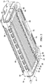
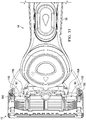
- a shaving system 10 is shown in FIG. 1 to include a cartridge 12 and a handle 14 that can cooperate to facilitate shaving of a user's skin.
- the cartridge 12 can extend between a front end 16 and a rear end 18 and can include a housing 20.
- the housing 20 can include a handle interface portion 22 that is disposed at the front end 16 and defines a handle receptacle 24 that facilitates attachment of the handle 14 to the cartridge 12.
- the housing 20 can also include a blade support portion 26 that is disposed at the rear end 18.
- the housing 20 can be formed of a thermoplastic material such as polyphenylene oxide. It is to be appreciated, however, that the housing 20 can be formed of any of a variety of suitable additional or alternative materials.
- a plurality of razor blades 28 can be disposed in the blade support portion 26 and can extend laterally between opposing sides 30 of the blade support portion 26.
- the razor blades 28 can be formed of stainless steel but can additionally or alternatively be formed of any of a variety of suitable materials (e.g., metals or non-metals). It is to be appreciated that although the razor blades 28 are shown to be straight razors, any of a variety of suitable alternative razor blades can be used, such as an array of rounded blades.
- the cartridge 12 can also have any number of blades depending on the desired performance and cost of the cartridge 12.
- the cartridge 12 can have, for example, one razor blade, two razor blades, three razor blades, four razor blades, five razor blades, six razor blades, seven razor blades, or even more razor blades.
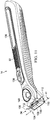
- the handle 14 can include a main body 32 and a pivoting head 34 pivotally coupled with the main body 32.
- the pivoting head 34 can be selectively inserted into the handle receptacle 24 to facilitate coupling of the cartridge 12 and the handle 14 together.
- a user can grasp the main body 32 of the handle 14 to facilitate shaving of the user's skin with the cartridge 12.
- the cartridge 12 can be a disposable-type cartridge that can be selectively removed from the handle 14 for replacement. Once the razor blades 28 have become dulled (or damaged) the consumer can disengage the cartridge 12 from the pivoting head 34 and replace the cartridge 12 with a new cartridge.
- the main body 32 can be provided with any of a variety of suitable gripping features, such as a patterned elastomeric coating, that provides for effective gripping of the main body 32 with the user's hand.
- the handle 14 can be of any suitable shape.
- the handle 14, for example, can be an elongated barrel shape or can be a contoured shape.
- the handle 14 can be made from any suitable material.
- the handle 14 can be made, for example, from a metal, a polymer, an elastomer, a plastic, a thermoplastic, a rubber, any other suitable material, or any combination thereof.
- the handle 14 can be made by any suitable process.
- the handle 14 can be made, for example, by molding, injection molding, insert injection molding, casting, die-casting, extruding, any other suitable method, or any combination thereof.
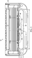
- the blade support portion 26 can comprise a cap 36 and a guard 38.
- the cap 36 can be positioned behind the razor blades 28 (e.g., at the rear end 18) and the guard 38 can be positioned in front of the razor blades 28 (e.g., between the razor blades 28 and the handle interface portion 22) such that the razor blades 28 are disposed between the cap 36 and the guard 38.
- the cap 36 and the guard 38 can cooperate to define a shaving plane P1 that is tangent to the cap 36 and the guard 38.
- a user's skin can be positioned against the cap 36 and guard 38 such that the user's skin extends along or into the shaving plane P1 for engagement by the razor blades 28 to facilitate shaving of the user's skin.
- the cap 36 can be a separate molded or extruded component that is mounted to the housing 20.
- the cap 36 can be, for example, a shaving aid filled reservoir, an extruded lubrication strip, and/or a plastic or metal bar to support the skin and further define the shaving plane P1.
- the cap 36 can be molded or extruded from the same material as the housing 20 or can be molded or extruded from a more lubricious shaving aid composite that has one or more water-leachable shaving aid materials to provide increased comfort during a shave stroke.
- the guard 38 can extend generally parallel to the razor blades 28 and can comprise a skin-engaging member 39 for stretching the skin during a shaving stroke.
- the skin-engaging member 39 is shown to be a segmented bar (e.g., that defines a plurality of fins) but can alternatively be a solid (e.g., smooth) bar.
- the skin-engaging member 39 can be, for example, insert injection molded or co-injection molded to the housing. Other known assembly methods can also be used such as adhering, bonding, attaching, ultrasonic welding, or mechanical fastening.
- the skin-engaging member 39 can be formed of a softer material (i.e., lower durometer hardness) than the housing 20.
- the skin-engaging member 39 can be formed of a material having a Shore A hardness of between about 20-70.
- the skin-engaging member 39 can be formed of thermoplastic elastomers (TPEs) or rubbers, some examples of which can include, but are not limited to, silicones, natural rubber, butyl rubber, nitrile rubber, styrene butadiene rubber, styrene butadiene styrene (SBS) TPEs, styrene ethylene butadiene styrene (SEBS) TPEs (e.g., Kraton), polyester TPEs (e.g., Hytrel), polyamide TPEs (Pebax), polyurethane TPEs, polyolefin based TPEs, and blends of any of these TPEs (e.g., polyester/SEBS blend).
- TPEs thermoplastic elastomers
- SEBS styrene ethylene butadiene
- the skin-engaging member 39 can comprise Kraiburg HTC 1028/96, HTC 8802/37, HTC 8802/34, or HTC 8802/11 (KRAIBURG TPE GmbH & Co. KG of Waldkraiburg, Germany).
- a softer material for the skin-engaging member 39 can enhance skin stretching, as well as provide a more pleasant tactile feel against the skin of the user during a shaving stroke.
- a softer material can also aid in masking the less pleasant feel of the harder material of the housing 20 and/or the razor blades 28 against the skin of the user during a shaving stroke.
- a trimmer assembly 40 can be provided on the rear end 18 of the cartridge 12 and held in place by a pair of clips 42.
- the trimmer assembly 40 can include a blade 44 that extends away from the shaving plane P1 and can be used for precise trimming of a user's hair (e.g., sideburns).
- the clips 42 can additionally facilitate retention of the razor blades 28 to the housing 20.
- Other assembly methods known to those skilled in the art can additionally or alternatively be used to secure and/or mount a trimmer assembly (e.g., 40) and/or razor blades (e.g., 28) to the housing 20 including, but not limited to, wire wrapping, cold forming, hot staking, insert molding, ultrasonic welding, and adhering.
- the clips 42 can be formed of a metal, such as aluminum, for example, which can facilitate conduction of heat and/or can serve as a sacrificial anode to help prevent corrosion of the razor blades 28.
- the handle interface portion 22 can include a front wall 46, a rear wall 48, and a pair of sidewalls 50.
- the rear wall 48 can be more proximate to the blade support portion 26 than the front wall 46.
- the rear wall 48 can be interposed between the handle interface portion 22 and the blade support portion 26 such that the rear wall 48 defines a portion of the blade support portion 26 (e.g., the handle interface portion 22 and the blade support portion 26 are immediately adjacent one another).
- the front wall 46 can include a front interior surface 52
- the rear wall 48 can include a rear interior surface 54
- each of the sidewalls 50 can include a respective side interior surface 56 ( FIG. 4 ).
- the front wall 46 can be spaced from the rear wall 48
- the sidewalls 50 can extend between the front wall 46 and the rear wall 48 and can be spaced from each other such that the front interior surface 52, the rear interior surface 54, and the side interior surfaces 56 cooperate to define a portion of the handle receptacle 24.
- Each of the front wall 46, the rear wall 48, and the sidewalls 50 can include respective lower surfaces 58, 60, 62.
- the lower surfaces 58, 60, 62 can cooperate to define a lower opening 64.
- the handle receptacle 24 can extend to the lower opening 64 and the lower opening 64 can be configured to allow for insertion of the pivoting head 34 of the handle 14 into the handle receptacle 24.
- the handle interface portion 22 can include an upper surface 66 that is located on an opposite side of the cartridge 12 as the lower surfaces 58, 60, 62.
- the upper surface 66 can define an upper opening 68 that is more proximate the shaving plane P1 than the lower opening 64.
- the upper opening 68 can define a perimeter M1.
- the perimeter M1 can be between about 45 mm and about 90 mm and preferably about 66.5 mm.
- the handle receptacle 24 can extend to the upper opening 68 and can be configured to allow for a portion of the pivoting head 34 of the handle 14 to project through the upper surface 66, as will be described in more detail below. It is to be appreciated that although the upper opening 68 is shown as an individual opening, the upper surface 66 can define any quantity of upper openings, such as, for example, a pair of upper openings.
- the lower opening 64 can have a length L1 that extends laterally along the handle interface portion 22 between the opposing sides 30 of the handle interface portion 22. It is to be appreciated that extending laterally can be understood to mean that the length L1 is measured in a direction that is perpendicular to the shaving direction of the cartridge 12 (e.g., the direction in which the cartridge 12 is pulled along the user's skin to facilitate shaving).
- the lower opening 64 can also have a width W1 that extends longitudinally along the handle interface portion 22 (e.g., between the front wall 46 and the rear wall 48). It is to be appreciated that extending longitudinally can be understood to mean that the width W1 is measured in a direction that is substantially parallel to the shaving direction of the cartridge 12.
- the upper opening 68 can have a length L2 that extends laterally along the handle interface portion 22 (e.g., between the shoulder portions 70 shown in FIG. 4 ).
- the upper opening 68 can have a width W2 that extends longitudinally along the handle interface portion 22.
- the lower opening 64 can generally be larger than the upper opening 68.
- the length L1 and width W1 of the lower opening 64 can be longer and wider, respectively, than the L2 and width W2 of the upper opening 68.
- the length L1 of the lower opening 64 can be between about 29 mm and about 39 mm, and preferably about 34 mm
- the length L2 of the upper opening 68 can be between about 26 mm and about 36 mm, and preferably about 31 mm.
- the width W1 of the lower opening 64 can be between about 3 mm and about 8 mm, and preferably about 6.5 mm and the width W2 of the upper opening 68 can be between about 1.5 mm and about 5 mm, and preferably about 3.6 mm.
- the relative size between the lower opening 64 and the upper opening 68 can provide an intuitive pathway for installation of the pivoting head 34 into the handle receptacle 24 and can also guide the pivoting head 34 into a fully installed position within the handle receptacle 24.
- the housing 20 of the cartridge 12 can define an overall width W0 that is measured longitudinally between the front end 16 and the rear end 18.
- the ratio of the overall width W0 of the housing 20 to the width W2 of the upper opening 68 can be between about 3:1 and about 2:1.
- the overall width W0 of the housing 20 can be between about 10 mm and about 11 mm.
- the front wall 46 can be shorter than the rear wall 48.
- the front wall 46 can have a vertical height H1 that is measured between the lower surface 58 of the front wall 46 (at the highest point) and the upper surface 66.
- the rear wall 48 can have a vertical height H2 that is measured between the lower surface 60 of the rear wall 48 (at the highest point) and the upper surface 66.
- the vertical height H1 can be less than the vertical height H2.
- the vertical height H1 can be between about 1.5 mm and about 7.5 mm, and preferably about 2.5 mm
- the vertical height H2 can be between about 7.5 mm and about 12 mm, and preferably about 9 mm.
- a vertical dimension e.g., a vertical distance or vertical height
- a vertical dimension can be understood to mean a dimension that is measured in a direction that is perpendicular to the shaving plane P1.
- the upper surface 66 can be within a vertical distance D1 of the shaving plane P1, which in some embodiments can be between about 0 mm (e.g., extending along the shave plane P1) and 1 mm, and preferably about 0.25 mm to 0.5 mm. In one embodiment, as illustrated in FIG. 6 , the upper surface 66 can be spaced from the shaving plane P1. In other embodiments, the upper surface 66 can define the shaving plane P1 such that the vertical distance D1 is substantially zero. The proximity of the upper surface 66 to the shave plane P1 can allow the pivoting head 34 of the handle 14 to effectively contact a user's skin during shaving to provide a benefit (e.g., lubricant or heat) thereto, as will be described in further detail below.
- a benefit e.g., lubricant or heat
- the handle interface portion 22 can include a pair of shoulder portions 70 that each extend to the upper surface 66 and cooperate with the upper surface 66 to at least partially define the upper opening 68.
- Each of the shoulder portions 70 comprise a shoulder surface 72 that interfaces with the front interior surface 52, the rear interior surface 54, and one of the side interior surfaces 56.
- the front wall 46, the rear wall 48, and each of the sidewalls 50 cooperate to define a perimeter M2 ( FIG. 4 ) that extends along the interface between the shoulder surface 72 and each of the front interior surface 52, the rear interior surface 54, and the side interior surfaces 56.
- Each shoulder portion 70 can extend laterally inwardly from the front wall 46, the rear wall 48, and one of the sidewalls 50 such that the perimeter M1 of the upper opening 68 is greater than the perimeter M2.
- the perimeter M2 can be between about 40 mm and about 100 mm and preferably between about 60 mm and about 80 mm.
- the location of the shoulder portions 70 at the sidewalls 50 can advantageously result in an overall size of the cartridge 12 that is longitudinally smaller than some conventional cartridge arrangements. All things being equal, consumers typically prefer razor cartridges that are longitudinally compact.
- the perimeter M1 of the upper opening 68 can be maximized which can enhance the contact of the pivoting head 34 with a user's skin, as will be appreciated from the additional discussion below.
- the shoulder surface 72 of one of the shoulder portions 70 is shown to be spaced from the shaving plane P1 by a vertical distance D2.
- the vertical distance D2 can be between about 0.5 mm and about 3 mm, and preferably about 1 mm.
- the vertical distance D2 can affect the control of the shaving geometry of the shaving system 10 and can influence the performance of the pivoting head 34 to provide benefit (e.g., heat or lubrication) to the skin through the upper opening 68, as will be described in further detail below.
- benefit e.g., heat or lubrication
- the handle interface portion 22 can include a front lip portion 74 that extends between the front wall 46 and the upper surface 66 and between the shoulder portions 70.
- the front lip portion 74 can include a lip surface 76 ( FIGS. 2 and 6 ) that extends between the front interior surface 52 and the upper surface 66.
- the lip surface 76 can be non-coplanar with the front interior surface 52 of the front wall 46.
- the lip surface 76 can extend along a plane P2 and the front interior surface 52 can extend along a plane P3 that is non-coplanar (e.g., angled) with respect to the plane P2.
- the lip surface 76 can be arranged such that the plane P2 is substantially perpendicular to the shaving plane P1.
- the front lip portion 74 can be configured to engage the pivoting head 34 of the handle 14.
- the rear wall 48 can include a central portion 78 and a pair of distal portions 80 ( FIG. 7 ) that each extend from the central portion 78 to one of the sidewalls 50.
- the rear wall 48 can be thinner at the distal portions 80 than at the central portion 78 such that each of the distal portions 80 defines a notch 82.
- the central portion 78 can have a thickness T1 and each of the distal portions 80 can have a thickness T2.
- the thickness T1 of the central portion 78 can be greater than the thickness T2 of the distal portions 80.
- the ratio of the first thickness T1 to the second thickness T2 can be about 3:1 to about 3:2.
- the thickness T1 can be between about 0.75 mm and about 3 mm, and preferably between about 1 mm and 2 mm, and the thickness T2 can be between about 0.5 mm and about 1 mm, and preferably between about 0.6 mm to 0.8 mm.
- each of the central portion 78 and the distal portions 80 can result in the rear interior surface 54 of the rear wall 48 at the distal portions 80 being spaced further from the front interior surface 52 of the front wall 46 than the rear interior surface 54 at the central portion 78 of the rear wall 48.
- the rear interior surface 54 at the central portion 78 of the rear wall 48 can be spaced from the front interior surface 52 by a horizontal distance D3.
- the rear interior surface 54 at the distal portion 80 can be spaced from the front interior surface 52 by a horizontal distance D4 that is greater than the horizontal distance D3.
- a horizontal distance can be understood to mean that a distance that is measured in a direction that is parallel to the shaving plane P1.
- each of the distal portions 80 might define an alternative notch (not shown) that only extends partially between the lower surface 60 and one of the shoulder portions 70 such that the notches are configured as recesses. It is also to be appreciated that while the notches 82 are described as being similar to each other, it is contemplated that the notches can alternatively be configured differently from each other.
- the rear interior surface 54 located at the central portion 78 of the rear wall 48 can extend to the upper surface 66 ( FIG. 6 ) and between the shoulder portions 70 and can be spaced from the lip surface 76 ( FIG. 6 ). As illustrated in FIG. 6 , the rear interior surface 54 can extend along a plane P4. In one embodiment, the plane P4 can be substantially perpendicular to the shaving plane P1.
- each of the front corners 84 can be configured to selectively flex relative to adjacent portions of the front wall 46 and the sidewalls 50
- each of the rear corners 86 can be configured to selectively flex relative to adjacent portions of the rear wall 48 and the sidewalls 50.
- each of the front corners 84 can have a moment of inertia that is less than the moment of inertia of the adjacent portions of the front wall 46 and the sidewalls 50
- each of the rear corners 86 can have a moment of inertia that is less than the moment of inertia of the adjacent portions of the rear wall 48 and the sidewalls 50.
- each of the front corners 84 and the rear corners 86 can have a moment of inertia that is less than about 2 mm 4 .
- the higher flexibility of the front and rear corners 84, 86 can allow the front and rear corners 84, 86 to effectively serve as frangible areas for when the cartridge 12 undergoes significant impact, such as when the shaving system 10 is dropped.
- the front and rear corners 84, 86 can be configured to break first when the cartridge 12 undergoes significant impact to prevent the blade support portion 26 from breaking and allowing the razor blades 28 to separate from the cartridge 12.
- any quantity (e.g., one, two, or three) and/or combination of the front and rear corners 84, 86 are contemplated to have a higher flexibility.
- the front interior surface 52 of the front wall 46 and the rear interior surface 54 of the central portion 78 of the rear wall 48 can be tapered inwardly towards the upper opening 68 such that the handle receptacle 24 is generally funnel-shaped below the shoulder portions 70.
- the front interior surface 52 and the rear interior surface 54 of the central portion 78 of the rear wall 48 can be angled relative to each other such that the planes P3, P4 intersect at an included angle ⁇ 1 (any angle that is less than 180 degrees) to define the funnel-shape of the handle receptacle 24.
- the included angle ⁇ 1 can be between about 30 degrees and 70 degrees, and preferably between about 45 degrees and about 48 degrees.
- the included angle ⁇ 1 can provide the front wall 46 and the rear wall 48 at an angle that narrows the handle receptacle 24 in the direction of the upper opening 68 to provide an intuitive pathway for installation of the pivoting head 34 through the lower opening 64 and can also guide the pivoting head 34 into a fully installed position within the handle receptacle 24.
- the front interior surface 52 of the front wall 46 and the rear interior surface 54 of the central portion 78 of the rear wall 48 can be generally planar such that the front interior surface 52 of the front wall 46 and the rear interior surface 54 of the central portion 78 of the rear wall 48 reside substantially entirely in the front and rear planes P3, P4, respectively.
- alternative non-planar surfaces are contemplated, such as, for example, surfaces that have at least one contoured area.
- the term extending in a plane can be understood to mean that the surface has at least two points that reside in the plane.
- the rear interior surface 54 of the central portion 78 of the rear wall 48 is discussed, any other portion of the rear interior surface 54 is also contemplated as defining the funnel shape of the handle receptacle 24.
- the funnel-shape of the handle receptacle 24 can result in the cross-sectional surface area of the handle receptacle 24 being larger proximate the lower opening 64 than proximate the upper opening 68.
- an upper cross-sectional area A1 can be defined by each of the front interior surface 52, the rear interior surface 54, and the side interior surfaces 56 proximate the upper opening 68.
- a lower cross-sectional area A2 can be defined by each of the front interior surface 52, the rear interior surface 54, and the side interior surfaces 56 at the lower opening 64.
- the upper cross-sectional area A1 can be more proximate the upper opening 68 than the lower cross-sectional area A2.
- the upper cross-sectional area A1 can be taken at a vertical distance of about 1 mm from the shaving plane P1.
- an intermediate cross-sectional area A3 can be defined by each of the front interior surface 52, the rear interior surface 54, and the side interior surfaces 56 and can be disposed between the upper cross-sectional area A1 and the lower cross-sectional area A2.
- the lower cross-sectional area A2 can be greater than the upper cross-sectional area A1.
- the intermediate cross-sectional area A3 can be less than the lower cross-sectional area A2 and greater than the upper cross-sectional area A1.
- the lower cross-sectional area A1 can be between about 60 mm 2 and about 250 mm 2 , and preferably about 155 mm 2 and the upper cross-sectional area A2 can be between about 40 mm 2 and about 120 mm 2 , preferably about 80 mm 2 .
- the upper cross-sectional area A1 can be understood to mean the smallest cross-sectional area that can be defined by each of the front interior surface 52, the rear interior surface 54, and the side interior surfaces 56 that is taken at a cross-section that is parallel to the shaving plane P1.
- the lower cross-sectional area A2 can be understood to mean the largest cross-sectional area that can be defined by each of the front interior surface 52, the rear interior surface 54, and the side interior surfaces 56 that is taken at a cross-section that is parallel to the shaving plane P1.
- the handle interface portion 22 can include a locking member 88 that is configured to facilitate selective retention of the pivoting head 34 ( FIG. 1 ) of the handle 14 within the handle receptacle 24.
- the locking member 88 can comprise a central member 90, a pair of support arms 92 and a deflection member 94.
- Each of the central member 90 and the support arms 92 can be coupled with the central portion 78 of the rear wall 48 and can extend from the rear wall 48.
- the deflection member 94 can comprise a pair of distal members 96 and a central portion 98 that is interposed between the distal members 96.
- the central member 90 can be coupled with the central portion 98 and each of the distal members 96 can be coupled with one of the support arms 92.
- each of the central member 90 and the support arms 92 can extend from the rear wall 48 such that the deflection member 94 is interposed between the front wall 46 and the plane P4 of the rear interior surface 54 of the rear wall 48.
- the locking member 88 can accordingly extend from the rear interior surface 54 of the central portion 78 of the rear wall 48 towards the front wall 46 such that the locking member 88 overhangs the rear wall 48.
- the locking member 88 can extend from the rear interior surface 54 at the central portion 78 of the rear wall 48 and towards the front wall 46 by a horizontal distance D5 that is between about 1 mm and 3 mm, and preferably between about 1.5 mm and 2.5 mm.
- the locking member 88 can engage the pivoting head 34 to facilitate retention of the pivoting head 34 in the handle receptacle 24.
- the deflection member 94 can include an upper surface 100 ( FIGS. 5 and 6 ) that is spaced from the lower surface 60 of the rear wall 48 such that the central member 90, the support arms 92, the upper surface 100 and the lower surface 60 cooperate to define a pair of slots 102 ( FIGS. 4 and 5 ) that extend between the rear wall 48 and the deflection member 94.
- the upper surface 100 of the deflection member 94 and the rear interior surface 54 at the central portion 78 of the rear wall 48 e.g., the plane P4
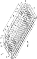
- the pivoting head 34 of the handle 14 can be configured for insertion into the handle receptacle 24 ( FIG. 1 ) to facilitate releasable attachment of the handle 14 with the cartridge 12.
- the pivoting head 34 can extend between an upper end 104 and a lower end 106.
- the pivoting head 34 can comprise a base member 108 and a cover member 110 that is coupled with the base member 108.
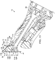
- the handle 14 can comprise a pair of arms 112 that are each spaced from one another and extend from the main body 32 and to the lower end 106 of the pivoting head 34. Each of the arms 112 can be rigidly coupled with the main body 32 of the handle 14.
- Each of the arms 112 can comprise a pin member 113 (also shown in FIGS. 14 and 34 ).
- Each of the pin members 113 can be pivotally coupled with the base member 108 such that the pivoting head 34 is pivotable about a pivot axis A1 defined by the pin members 113.
- a spring e.g., 156 in FIG. 34
- the handle 14 can provide one or more pivot motions for the pivoting head 34.
- the pivot axis A1 can be generally transverse to the handle 14.
- the handle 14 is shown to include a pair of arms 112, it is to be appreciated that a handle can be provided with any other quantity of arms such as one arm or more than two arms.
- the base member 108 can include a front wall 114, a rear wall 116, and a head portion 118 that extends upwardly from the front and rear walls 114, 116 such that the front wall 114, the rear wall 116, and the head portion 118 cooperate to define a trapezoidal prism-shape.
- the front wall 114 can include a front exterior surface 120 and a pair of side exterior surfaces 122 (one shown) that extend from the front exterior surface 120 and towards the rear wall 116.
- the rear wall 116 can include a rear exterior surface 124 and a pair of side exterior surfaces 126 (one shown) that extend from the rear exterior surface 124 and towards the front wall 114.
- the front wall 114 and the rear wall 116 are angled with respect to each other and cooperate with each other define a pair of V-shaped grooves 128 (one shown) at the side exterior surfaces 122, 126. As illustrated in FIGS. 11 and 12 , the arms 112 can extend along the V-shaped grooves 128 and can be configured to travel within the V-shaped grooves 128 when the pivoting head 34 is pivoted.
- the head portion 118 can comprise a face surface 130 that defines a pair of apertures 132.
- the apertures 132 can be in fluid communication with a fluid distribution system that facilitates dispensation of shaving fluid, such as, for example, shaving cream or shaving lotion.
- the fluid distribution system can comprise a reservoir 136, a dispensing button 138, and a fluid delivery member 140.
- the reservoir 136 can be in fluid communication with the fluid delivery member 140 which can be in fluid communication with the apertures 132 ( FIG. 12 ) of the head portion 118.
- the dispensing button 138 can be fluidly interposed between the reservoir 136 and the fluid delivery member 140 and can be configured to facilitate selective dispensation of the shaving fluid stored in the reservoir 136 through the apertures 132 ( FIG. 12 ).
- a user can depress the dispensing button 138 while shaving to dispense the shaving fluid to the user's skin.
- the shaving fluid can comprise a water-insoluble polymer and a skin-lubricating water-soluble polymer.
- Suitable water-insoluble polymers which can be used include, but are not limited to, polyethylene, polypropylene, polystyrene, butadiene-styrene copolymer (e.g., medium and high impact polystyrene), polyacetal, acrylonitrile-butadiene-styrene copolymer, ethylene vinyl acetate copolymer and blends such as polypropylene/polystyrene blend and can have a high impact polystyrene (i.e., Polystyrene-butadiene), such as Mobil 4324 (Mobil Corporation).
- Suitable skin lubricating water-soluble polymers can include polyethylene oxide, polyvinyl pyrrolidone, polyacrylamide, hydroxypropyl cellulose, polyvinyl imidazoline, and polyhydroxyethylmethacrylate.
- Other water-soluble polymers can include the polyethylene oxides generally known as POLYOX (available from Union Carbide Corporation) or ALKOX (available from Meisei Chemical Works, Kyota, Japan). These polyethylene oxides can have molecular weights of about 100,000 to 6 million, for example, about 300,000 to 5 million.
- the polyethylene oxide can comprise a blend of about 40 to 80% of polyethylene oxide having an average molecular weight of about 5 million (e.g., POLYOX COAGULANT) and about 60 to 20% of polyethylene oxide having an average molecular weight of about 300,000 (e.g., POLYOX WSR-N-750).
- the polyethylene oxide blend can also contain up to about 10% by weight of a low molecular weight (i.e., molecular weight of less than about 10,000) polyethylene glycol such as PEG-100.
- the shaving fluid can also include a complex of a skin-soothing agent with a cylcodextrin, low molecular weight water-soluble release enhancing agent such as polyethylene glycol (e.g., 1-10% by weight), water-swellable release enhancing agents such as cross-linked polyacrylics (e.g., 2-7% by weight), colorants, antioxidants, preservatives, microbicidal agents, beard softeners, astringents, depilatories, medicinal agents, conditioning agents, moisturizers, cooling agents, and the like.
- a skin-soothing agent with a cylcodextrin low molecular weight water-soluble release enhancing agent such as polyethylene glycol (e.g., 1-10% by weight), water-swellable release enhancing agents such as cross-linked polyacrylics (e.g., 2-7% by weight), colorants, antioxidants, preservatives, microbicidal agents, beard softeners, astringents, dep
- the head portion 118 can comprise an exterior lip surface 146 that extends between the front and rear walls 114, 116 and the face surface 130.
- the front wall 114 and the head portion 118 can be angled with respect to each other such that the front exterior surface 120 and the exterior lip surface 146 are non-coplanar.
- the exterior lip surface 146 can extend along a plane P5
- the front exterior surface 120 of the front wall 114 can extend along a plane P6 that is non-coplanar with the plane P5.
- Each of the exterior lip surface 146 and the front exterior surface 120 can be generally planar such that the exterior lip surface 146 and the front exterior surface 120 reside substantially entirely in the plane P6.
- the angle of the front exterior surface 120 and the exterior lip surface 146 can generally correspond to the angle between the front wall 46 and the front lip portion 74 of the cartridge 12 (e.g., the angle between plane P2 and P3 shown in FIG. 6 ) to allow for proper insertion of the pivoting head 34 into the handle receptacle 24.
- the head portion 118 can have a vertical height H3 that can be between about 0.5 mm and about 2 mm, and preferably between about 0.9 mm and about 1.0 mm. It is to be appreciated that a vertical dimension (e.g., height or distance) on the handle 14 can be understood to mean that the dimension is measured in a direction that is perpendicular to the shaving plane P1 when the pivoting head 34 is installed on the cartridge 12.
- the front wall 114 can have a vertical height H4 that can be between about 1.5 and about 5 mm, and preferably about 3.1 mm.
- the rear wall 116 can have a vertical height H5 that can be between about 5.5 mm and about 12 mm, and preferably between about 7 mm and about 9 mm.
- the rear exterior surface 124 of the central portion 148 of the rear wall 116 can extend along a plane P7.
- the rear exterior surface 124 of the central portion 148 of the rear wall 116 can be generally planar such that the rear exterior surface 124 of the central portion 148 of the rear wall 116 resides substantially entirely in the plane P7. It is to be appreciated, however, that alternative non-planar surfaces are contemplated, such as, for example, surfaces that have at least one contoured area.
- the rear wall 116 can include a central portion 148 and a pair of tab members 150 that are disposed at opposite ends of the central portion 148.
- the tab members 150 can be thicker than the central portion 148 such that the tab members 150 protrude longitudinally (e.g., rearwardly) relative to the central portion 148.
- the central portion 148 can have a thickness T3 and each of the tab members 150 can have a thickness T4 that is greater than the thickness T3 of the central portion 148.
- the ratio of the thickness T4 to the thickness T3 can be between about 3:1 and about 3:2.
- the thickness T4 can be between about 0.75 mm and about 3 mm, and preferably about 0.9 mm to about 1.0 mm, and the thickness T3 can be between about 0.5 mm and about 1 mm, and preferably between about 0.8 mm to about 0.9 mm.
- the tab members 150 are shown in FIG. 14 to extend substantially entirely between the lower end 106 of the pivoting head 34 and the head portion 118. However, it is to be appreciated that other tab member configurations are contemplated. For example, tab members might only extend partially between the lower end 106 of the pivoting head 34 and the head portion 118 such that they are spaced from one or more of the lower end 106 of the pivoting head 34 and the head portion 118. It is also to be appreciated that while the tab members 150 are described as being similar to each other, it is contemplated that tab members can alternatively be configured differently from each other.
- the head portion 118 can have a length L3 that extends laterally along the pivoting head 34.
- the head portion 118 can also have a width W3 that extends longitudinally along the pivoting head 34.
- the length L3 and the width W3 of the head portion 118 can be slightly smaller than the length L2 and the width W2 of the upper opening 68 ( FIG. 5 ) to allow the head portion 118 to fit within the upper opening 68 when the pivoting head 34 is installed in the handle receptacle 24.
- the pivoting head 34 can comprise a pair of shoulder portions 152 that each extend laterally between the front wall 114, the rear wall 116, and the head portion 118 and are each disposed on opposite sides of the head portion 118.
- Each of the shoulder portions 152 comprise a shoulder surface 154 that interfaces with a portion of each of the front exterior surface 120, the side exterior surfaces 122, the rear exterior surface 124, the side exterior surfaces 126, and the exterior lip surface 146.
- the front exterior surface 120 of the front wall 114 and the rear exterior surface 124 of the central portion 148 of the rear wall 116 can be tapered inwardly towards the head portion 118 such that the pivoting head 34 is generally funnel-shaped below the shoulder portions 152.
- the front exterior surface 120 and the rear exterior surface 124 of the central portion 148 of the rear wall 116 can be angled relative to each other such that the planes P6, P7 intersect at an included angle ⁇ 3 (any angle that is less than 180 degrees) to define the funnel-shape of the pivoting head 34.
- the included angle ⁇ 2 can be between about 30 degrees and 70 degrees, and preferably between about 45 degrees and about 48 degrees.
- the funnel-shape of the pivoting head 34 below the shoulder portions 152 can correspond to the funnel shape of the handle receptacle 24 such that the pivoting head 34 fits snugly in the handle receptacle 24 when the pivoting head 34 is inserted into the handle receptacle 24.
- the pivoting head 34 can have a lower length L4 at the lower end 106 that extends laterally and is defined by the front wall 114 and the rear wall 116.
- the pivoting head 34 can also have a lower width W4 at the lower end 106 that extends longitudinally and is defined by the front wall 114 and the rear wall 116.
- the pivoting head 34 can have an upper length L5 at the upper end 104 that extends laterally and is defined by the front wall 114 and the rear wall 116.
- the pivoting head 34 can also have an upper width W5 at the upper end 104 that extends longitudinally and is defined by the front wall 114 and the rear wall 116.
- the lower end 106 of the pivoting head 34 can generally be larger than the upper end 104.
- the lower length L4 and the lower width W4 of the pivoting head 34 at the lower end 106 can be longer and wider, respectively, than the upper length L5 and the upper width W5 of the pivoting head 34 at the upper end 104.
- the lower length L4 can be between about 25 mm and about 55 mm, and preferably about 35 mm
- the lower width W4 can be between about 3 mm and about 8 mm, and preferably about 3.9 mm.
- the upper length L5 can be between about 20 mm and about 40 mm, and preferably about 30 mm
- the upper width W5 can be between about 1 mm and about 6 mm, and preferably about 3.4 mm.
- the main body 32 of the handle 14 can be laid substantially flat (e.g., substantially parallel to the shaving plane P1) to provide the pivoting head 34 in such a position.
- the handle 14 can then be moved towards the cartridge 12 proximate the handle receptacle 24.
- the vertical height H1 of the front wall 46 can be shorter than the vertical height H2 of the rear wall 48.
- the front wall 46 can provide sufficient clearance for inserting the pivoting head 34 into the handle receptacle 24 from the front of the cartridge 12.
- the pivoting head 34 can pass over the front wall 46 and into the handle receptacle 24 while remaining spaced from the rest of the cartridge 12 (e.g., the locking member 88).
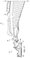
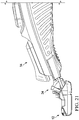
- the handle 14 can then be moved further towards the cartridge 12 and pivoted slightly upwardly to further insert the pivoting head 34 into the handle receptacle 24 ( FIG. 23 ).
- the front wall 114 and the head portion 118 of the pivoting head 34 are shown in FIG. 23 to contact the front wall 46 to facilitate guiding of the pivoting head 34 into the handle receptacle 24.
- the rear wall 116 can alternatively contact the locking member 88 to facilitate guidance of the pivoting head 34 into the handle receptacle 24.
- the side exterior surfaces 122, 126 of the front wall 114 and the rear wall 116 (shown in FIG. 16 ), respectively, can additionally contact the sidewalls 50 ( FIG.
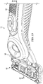
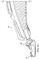
- pivoting head 34 can eventually contact each of the front wall 46 and the rear wall 48, as illustrated in FIGS. 24-26 .
- the front wall 46 and the rear wall 48 can deflect, as illustrated in FIGS. 27-29 .
- the deflection of the front and rear walls 46, 48 can be facilitated by the flexibility of the front and rear corners 84, 86 ( FIG. 7 ) described above. It is to be appreciated that although both the front and rear walls 46, 48 are shown to deflect, only one of the front wall 46 or the rear wall 48 might deflect to allow for insertion of the pivoting head 34 into the handle receptacle 24.
- the pivoting head 34 can be further inserted into the handle receptacle 24 (e.g., by continuing to move the handle 14 further towards the cartridge 12 and/or by pivoting the handle 14 further upwardly) until the pivoting head 34 is fully installed in the handle receptacle 24, as illustrated in FIGS. 30-32 .
- FIG. 32 when the pivoting head 34 is fully installed in the handle receptacle 24 ( FIG. 17 ), the front and rear walls 46, 48 are no longer deflected and the locking member 88 overhangs the rear wall 116 and a portion of the cover member 110.
- the angle ⁇ 2 ( FIG. 6 ) of the locking member 88 can effectively angle the locking member 88 towards the pivoting head 34.
- the portions of the cover member 110 and the rear wall 116 that are disposed above the locking member 88 can have an angled shape that corresponds with the angle ⁇ 2 of the locking member 88.
- the angle ⁇ 2 of the locking member 88 can effectively enhance the securement of the pivoting head 34 within the handle receptacle 24 by discouraging inadvertent separation of the cartridge 12 from the handle 14.
- the angle ⁇ 2 of the locking member 88 can also facilitate effective retention of the pivoting head 34 to the cartridge 12 when the trimmer assembly 40 is used to shave a user's skin.
- the cartridge 12 does not comprise a pivot mechanism in and of itself.
- the interface between the cartridge 12 and the handle 14 does not comprise a pivot mechanism in and of itself.
- the pivoting head 34 and the cartridge 12 are selectively locked together and while they do not pivot relative to one another, they pivot together relative to the handle 14 about the pivot axis A1 ( FIG. 11 ).
- the overall funnel-shape of the handle receptacle 24 described above can correspond to the trapezoidal prism-shape of the pivoting head 34 described above such that pivoting head 34 nests within the handle receptacle 24 when fully installed.
- the front and rear walls 114, 116 of the pivoting head 34 can be seated against the front and rear walls 46, 48 of the cartridge 12, respectively.
- the side exterior surfaces 122,126 of the front and rear walls 114,116 ( FIG. 16 ), respectively, can be seated against the sidewalls 50.
- Such nesting of the pivoting head 34 within the handle receptacle 24 can enhance the securement of the pivoting head 34 to the cartridge 12 to inhibit any undesired movement therebetween during shaving.
- the relative shapes of the handle receptacle 24 and the pivoting head 34 can result in a tight fit between the cartridge 12 and the pivoting head 34 which can provide smaller gaps between the cartridge 12 and the pivoting head 34 by virtually eliminating the small radii and abrupt corners that are difficult to manufacture in the mating surfaces of two components. These smaller gaps provide for a more comfortable skin contacting surface during shaving by preventing areas where hair or other shave debris can be trapped, especially around tight places, such as the neck and underarms.
- the head portion 118 of the pivoting head 34 can project at least partially into the upper opening 68 such that the head portion 118 is exposed at the upper surface 66 and to a user's skin at the shaving plane P1.
- the head portion 118 can contact the user's skin to distribute any shaving fluid dispensed from the apertures 132 ( FIG. 12 ) to the user's skin ahead of the razor blades 28.
- the shaving fluid can accordingly lubricate the skin prior to being shaved by the razor blades 28.
- the shaving system 10 can accordingly be configured to deliver benefits (e.g., lubrication) to the user's skin by extending the head portion 118 of the pivoting head 34 through the upper opening 68 ( FIG. 5 ).
- the head portion 118 can project through the upper opening 68 such that the face surface 130 protrudes from the upper surface 66 and is spaced from the upper surface 66 by a vertical distance D6.
- the vertical distance D6 can be substantially similar to the vertical distance D1 described above with respect to FIG. 6 such that the face surface 130 extends along the shaving plane P1.
- the vertical distance D6 can be between about 0.25 mm and about 1 mm, and preferably about 0.5 mm.
- the vertical distance D6 can be selected to be greater than or less than the vertical distance D1 such that the face surface 130 is disposed respectively above or below the shaving plane P1.
- the head portion 118 of the pivoting head 34 can project into the upper opening 68 such that the face surface 130 is substantially flush with the upper surface 66. In yet another embodiment, the head portion 118 of the pivoting head 34 can project partially into the upper opening 68 such that the head portion 118 is recessed within the upper opening 68. It is to be appreciated that location of the face surface 130 relative to the shaving plane P1 can be determined by the relative distance D2 ( FIG. 6 ) between the shoulder surface 72 and the shaving plane P1 and the vertical height H3 ( FIG. 13 ) of the head portion 118.
- the rear wall 116 of the pivoting head 34 can be seated against the rear wall 48 of the cartridge 12 such that the tab members 150 of the pivoting head 34 extend into respective ones of the notches 82 of the rear wall 48.
- the tab members 150 can each define a length L6 and the pin members 113 can each define a length L7 that is less than the length L6 of the tab members 150.
- the pin members 113 can be spaced from each other by a distance D7.
- the central portion 148 of the rear wall 116 can have a length L8 that extends laterally and is less than the distance D7.
- the pin members 113 of the arms 112 can be disposed within respective ones of the tab members 150 which can allow the pin members 113 to be located nearer to the blade support portion 26 than would be possible at the central portion 148 of the rear wall 116.
- the pivot axis A1 defined by the pin members 113 can be spaced from the nearest razor blade 28 by a distance D8 which can be less than conventional arrangements and without sacrificing the structural integrity achieved by those conventional arrangements.
- the location of the pivot axis A1 relatively close to the nearest shaving blade 28 can allow the cartridge 12 to follow the skin more closely during a shave stroke and with less blade tip pressure thereby providing a smoother, more comfortable, and more effective shave.
- the distance D8 can be between about 0.7 mm and about 2.5 mm and preferably about 2.0 mm and more preferably about 1.5 mm.
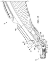
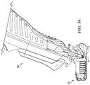
- the handle 14 can pivot about the pivot axis A1 relative to the cartridge 12 between a home position as illustrated in FIG. 35 and a fully pivoted position as illustrated in FIG. 36 to allow the cartridge 12 to contour to the user's skin.
- the arms 112 can travel within the V-shaped grooves 128 to allow for pivoting of the pivoting head 34 and thus the cartridge 12 between the home position and the fully pivoted position.
- the V-shaped grooves 128 can define the pivot limits of the home position and the fully pivoted position of the pivoting head 34.
- a spring 156 as illustrated in FIG. 34 , can be disposed between the base member 108 and the cover member 110 ( FIG. 11 ) and can comprise a pair of arms 158 ( FIG.
- the spring 156 can bias the pivoting head 34 into the home position such that when a user shaves with the shaving system 10, the spring 156 can maintain contact between the cartridge 12 and the user's skin. It is to be appreciated that the pivot limits and biasing can be accomplished by any means known in the art, including mechanical limits.
- the handle 14 can comprise an ejection button 160 that is slidable between a retracted position (shown in solid lines) and an extended position (shown in dashed lines).
- the ejection button 160 can be slid from the retracted position to the extended position to facilitate ejection of the cartridge 12 from the handle 14.
- the shaving system 10 is being used for shaving the ejection button 160 can be biased into the retracted position.
- the user can push the ejection button 160 towards the extended position and into contact with the deflection member 94 of the locking member 88.
- the user can further urge the ejection button 160 towards the extended position until the pivoting head 34 is out of engagement with the locking member 88 (e.g., into the position shown in FIGS. 27-29 ) and can be removed from the cartridge 12.
- the ejection button 160 can be spaced from the locking member 88 by a distance D9 that is sufficient to prevent interference between the ejection button 160 and the locking member 88 when the cartridge 12 is pivoted into the fully pivoted position, as illustrated in FIG. 36 .
- the distance D9 can be between about 2.0 mm and about 5.0 mm and preferably about 3.0 mm.
- FIGS. 37 and 38 illustrate an alternative embodiment of a shaving system 1010 that includes a cartridge 1012 and a handle 1014 that can be similar to, or the same as in many respects as, the cartridge 12 and the handle 14, respectively, illustrated in FIGS. 1-36 .
- the cartridge 1012 can comprise a plurality of razor blades 1028.
- the handle 1014 can comprise a main body 1032 and a pivoting head 1034 pivotally coupled with the main body 1032.
- the pivoting head 1034 can be configured for releasable attachment to the cartridge 1012 in a similar manner as described above with respect to FIGS. 1-36 .
- the pivoting head 1034 can comprise a head portion 1118.
- the head portion 1118 can comprise a heating element 1162 ( FIG.
- the heating system 1164 can comprise a power storage device 1166 and a heating controller 1168 that is in electrical communication with the power storage device 1166.
- a power button 1170 can be in electrical communication with the heating element 1162 and the heating controller 1168.
- the power button 1170 can be configured to facilitate selective energization of the heating element 1162.
- the heating controller 1168 can regulate the power flow from the power storage device 1166 to the heating element 1162 to regulate the amount of heat generated by the heating element 1162.
- the power storage device 1166 can comprise a rechargeable battery that can be recharged with a power cord or through inductive charging.
- the power storage device 1166 can comprise a disposable battery.
- the head portion 1118 can contact the user's skin to heat the user's skin ahead of the razor blades 1028. As the user pulls the cartridge 1012 across their skin, the heat can soften the skin prior to being shaved by the razor blades 1028.
- the heating element 1162 can comprise a metal such as aluminum or stainless steel.
- the heating element 1162 can comprise a high capacity material such as metal or phase change materials.
- the heating element 1162 can comprise high thermal conductivity materials such as copper, aluminum, or thermally conductive plastics such as CoolPoly® (trademark symbol).
- pivoting head 1034 is described as selectively heating a user's skin, the pivoting head 1034 can additionally or alternatively be configured to facilitate selective cooling of the user's skin. In some embodiments, heating or cooling delivered by the pivoting head 1034 can also be achieved passively such as by dipping or running the pivoting head 1034 under water at a different temperature than ambient.
- the cartridge 1012 can be similar to, or the same as in many respects as, the cartridge 12, illustrated in FIGS. 1-36 .
- the cartridge 1012 can comprise a rear wall 1048 that partially defines a lower opening 1064 and an upper opening 1068.
- the cartridge 1012 can comprise a pair of locking members 1088 that are spaced from each other and extend from the rear wall 1048 about midway between the lower opening 1064 and the upper opening 1068.
- the handle can weigh two to three times more than most wet shaving razor systems commonly found on the market. For instance, most conventional shaving razor handles weigh less than 56 grams, and the vast majority weighs less than 45 grams.
- the handles (e.g., 14, 1014) of the present disclosure can have a mass up to about 120 grams with preferred mass of about 80 grams. In some embodiments, the handle (e.g., 14, 1014) can have a mass of about 57 grams to about 150 grams and more preferably about 80 grams. Such a mass is considered "heavy" in the present disclosure.
- the handle 14 shown in FIGS. 1 and 11-16 can have a mass about 75 grams and the handle 1014 shown in FIGS. 37 and 38 has a mass of about 85 grams.
Landscapes
- Life Sciences & Earth Sciences (AREA)
- Forests & Forestry (AREA)
- Engineering & Computer Science (AREA)
- Mechanical Engineering (AREA)
- Dry Shavers And Clippers (AREA)
- Packaging Of Annular Or Rod-Shaped Articles, Wearing Apparel, Cassettes, Or The Like (AREA)
- Cosmetics (AREA)
- Physics & Mathematics (AREA)
- Geometry (AREA)
Claims (14)
- Rasierergriff (14, 1014), umfassend:einen Hauptkörper (32, 1032);ein Paar Arme (112), die sich von dem Hauptkörper (32, 1032) erstrecken;einen Schwenkkopf (34, 1034), der sich zwischen einem oberen Ende (104) und einem unteren Ende (106) erstreckt, wobei der Schwenkkopf (34, 1034) Folgendes umfasst:
ein Basiselement (108), das schwenkbar mit dem Paar von Armen (112) gekoppelt ist, um das Schwenken des Schwenkkopfs (34, 1034) um eine Schwenkachse zwischen einer Ausgangsposition und einer vollständig geschwenkten Position zu ermöglichen, wobei das Basiselement (108) Folgendes umfasst:eine Vorderwand (114), die eine erste vertikale Höhe umfasst; undeine Rückwand (116), die eine zweite vertikale Höhe umfasst;ein Vorspannelement, das betriebsfähig mit dem Hauptkörper (32, 1032) gekoppelt und konfiguriert ist, um den Schwenkkopf (34, 1034) in die Ausgangsposition vorzuspannen, wobei die erste vertikale Höhe geringer ist als die zweite vertikale Höhe, dadurch gekennzeichnet, dass die Vorderwand (114) und die Rückwand (116) in Bezug aufeinander abgewinkelt sind und ein Paar V-förmige Nuten (128) definieren und sich jeder Arm des Paares Arme (112) zwischen dem Paar V-förmige Nuten (128) erstreckt und konfiguriert ist, um sich innerhalb des Paares V-förmige Nuten (128) zu bewegen, wenn der Schwenkkopf (34, 1034) geschwenkt wird. - Rasierergriff (14, 1014) nach Anspruch 1, wobei die erste vertikale Höhe zwischen 1,5 mm und 5 mm beträgt.
- Rasierergriff (14, 1014) nach Anspruch 2, wobei die erste vertikale Höhe 3,1 mm beträgt.
- Rasierergriff (14, 1014) nach Anspruch 3, wobei die zweite vertikale Höhe zwischen 5,5 mm und 12 mm beträgt.
- Rasierergriff (14, 1014) nach Anspruch 4, wobei die zweite vertikale Höhe 8 mm beträgt.
- Rasierergriff (14, 1014) nach einem der vorstehenden Ansprüche, wobei:der Schwenkkopf (34, 1034) eine untere Länge am unteren Ende (106) umfasst, die sich seitlich erstreckt und durch die Vorderwand (114) und die Rückwand (116) definiert ist;der Schwenkkopf (34, 1034) eine obere Länge am oberen Ende (104) umfasst, die sich seitlich erstreckt und durch die Vorderwand (114) und die Rückwand (116) definiert ist; unddie untere Länge des Schwenkkopfes (34, 1034) am unteren Ende (106) länger ist als die obere Länge des Schwenkkopfes (34, 1034) am oberen Ende (104).
- Rasierergriff (14, 1014) nach Anspruch 6, wobei:die untere Länge zwischen 25 mm und 55 mm beträgt; unddie obere Länge zwischen 20 mm und 40 mm beträgt.
- Rasierergriff (14, 1014) nach Anspruch 7, wobei:die untere Länge 35 mm beträgt; unddie obere Länge 30 mm beträgt.
- Rasierergriff (14, 1014) nach einem der vorstehenden Ansprüche, wobei:der Schwenkkopf (34, 1034) eine untere Breite am unteren Ende (106) umfasst, die sich in Längsrichtung erstreckt und durch die Vorderwand (114) und die Rückwand (116) definiert ist;der Schwenkkopf (34, 1034) eine obere Breite am oberen Ende (104) umfasst, die sich in Längsrichtung erstreckt und durch die Vorderwand (114) und die Rückwand (116) definiert ist; unddie untere Breite des Schwenkkopfes (34, 1034) am unteren Ende (106) breiter als die obere Breite des Schwenkkopfes (34, 1034) am oberen Ende (104) ist.
- Rasierergriff (14, 1014) nach Anspruch 9, wobei:die untere Breite zwischen 3 mm und 8 mm beträgt; unddie obere Breite zwischen 1 mm und 6 mm beträgt.
- Rasierergriff (14, 1014) nach Anspruch 10, wobei:die untere Breite 3,9 mm beträgt; unddie obere Breite 3,4 mm beträgt.
- Rasierergriff (14, 1014) nach einem der vorstehenden Ansprüche, ferner umfassend einen Kopfabschnitt (1118), der sich von der Vorderwand (114) und der Rückwand (116) nach oben erstreckt und eine Lippenaußenoberfläche (146) und eine Stirnfläche (130) umfasst, wobei die Stirnfläche (130) eine Öffnung definiert, die im Fluidaustausch mit einem Flüssigkeitsbehälter (136) steht.
- Rasierergriff (14, 1014) nach Anspruch 12, wobei der Kopfabschnitt (1118) mindestens teilweise aus einem leitfähigen Material gebildet ist.
- Rasierergriff (14, 1014) nach Anspruch 13, wobei das leitfähige Material in elektrischer Verbindung mit einem Heizregler (1168) steht.
Applications Claiming Priority (1)
| Application Number | Priority Date | Filing Date | Title |
|---|---|---|---|
| US201862650663P | 2018-03-30 | 2018-03-30 |
Publications (2)
| Publication Number | Publication Date |
|---|---|
| EP3549729A1 EP3549729A1 (de) | 2019-10-09 |
| EP3549729B1 true EP3549729B1 (de) | 2021-05-19 |
Family
ID=66000997
Family Applications (10)
| Application Number | Title | Priority Date | Filing Date |
|---|---|---|---|
| EP20170654.6A Active EP3705246B1 (de) | 2018-03-30 | 2019-03-28 | Rasiererhandgriff |
| EP19165794.9A Active EP3552779B1 (de) | 2018-03-30 | 2019-03-28 | Rasiererkopf |
| EP19165819.4A Active EP3552781B1 (de) | 2018-03-30 | 2019-03-28 | Rasiererkopf |
| EP20170649.6A Active EP3705245B1 (de) | 2018-03-30 | 2019-03-28 | Rasiererhandgriff |
| EP19722235.9A Active EP3774225B1 (de) | 2018-03-30 | 2019-03-28 | Rasiererkopf |
| EP19165801.2A Active EP3552780B1 (de) | 2018-03-30 | 2019-03-28 | Rasiererkopf |
| EP19165817.8A Active EP3549729B1 (de) | 2018-03-30 | 2019-03-28 | Rasiererkopf |
| EP19165823.6A Active EP3552782B1 (de) | 2018-03-30 | 2019-03-28 | Rasiererkopf |
| EP19165815.2A Active EP3549728B1 (de) | 2018-03-30 | 2019-03-28 | Rasierergriff |
| EP19717071.5A Pending EP3774223A1 (de) | 2018-03-30 | 2019-03-28 | Rasiererkopf |
Family Applications Before (6)
| Application Number | Title | Priority Date | Filing Date |
|---|---|---|---|
| EP20170654.6A Active EP3705246B1 (de) | 2018-03-30 | 2019-03-28 | Rasiererhandgriff |
| EP19165794.9A Active EP3552779B1 (de) | 2018-03-30 | 2019-03-28 | Rasiererkopf |
| EP19165819.4A Active EP3552781B1 (de) | 2018-03-30 | 2019-03-28 | Rasiererkopf |
| EP20170649.6A Active EP3705245B1 (de) | 2018-03-30 | 2019-03-28 | Rasiererhandgriff |
| EP19722235.9A Active EP3774225B1 (de) | 2018-03-30 | 2019-03-28 | Rasiererkopf |
| EP19165801.2A Active EP3552780B1 (de) | 2018-03-30 | 2019-03-28 | Rasiererkopf |
Family Applications After (3)
| Application Number | Title | Priority Date | Filing Date |
|---|---|---|---|
| EP19165823.6A Active EP3552782B1 (de) | 2018-03-30 | 2019-03-28 | Rasiererkopf |
| EP19165815.2A Active EP3549728B1 (de) | 2018-03-30 | 2019-03-28 | Rasierergriff |
| EP19717071.5A Pending EP3774223A1 (de) | 2018-03-30 | 2019-03-28 | Rasiererkopf |
Country Status (8)
| Country | Link |
|---|---|
| US (8) | US10864646B2 (de) |
| EP (10) | EP3705246B1 (de) |
| JP (2) | JP2021516577A (de) |
| CN (2) | CN111886115B (de) |
| AU (2) | AU2019243158B2 (de) |
| BR (2) | BR112020020117A2 (de) |
| CA (2) | CA3091284A1 (de) |
| WO (2) | WO2019191344A1 (de) |
Families Citing this family (25)
| Publication number | Priority date | Publication date | Assignee | Title |
|---|---|---|---|---|
| USD877983S1 (en) * | 2016-09-09 | 2020-03-10 | The Gillette Company Llc | Shaving razor cartridge |
| EP3292965B1 (de) | 2016-09-09 | 2021-05-26 | The Gillette Company LLC | Rasiererklingenkopf und verfahren zur montage |
| US11117278B2 (en) | 2017-06-06 | 2021-09-14 | The Gillette Company Llc | Shaving razor cartridge |
| KR101876232B1 (ko) * | 2018-01-02 | 2018-07-10 | 주식회사 도루코 | 면도기 카트리지 |
| CA3091481C (en) * | 2018-03-30 | 2022-11-29 | The Gillette Company Llc | Shaving razor system including skin interconnect member |
| WO2019191344A1 (en) * | 2018-03-30 | 2019-10-03 | The Gillette Company Llc | Shaving razor cartridge |
| CN111867795B (zh) | 2018-03-30 | 2022-03-18 | 吉列有限责任公司 | 剃刀柄部 |
| JP2021517043A (ja) | 2018-03-30 | 2021-07-15 | ザ ジレット カンパニー リミテッド ライアビリティ カンパニーThe Gillette Company Llc | 枢動部分を有するかみそりハンドル |
| US11607820B2 (en) | 2018-03-30 | 2023-03-21 | The Gillette Company Llc | Razor handle with movable members |
| EP3546156B1 (de) | 2018-03-30 | 2021-03-10 | The Gillette Company LLC | Rasierergriff mit einem schwenkbaren teil |
| WO2019191345A1 (en) | 2018-03-30 | 2019-10-03 | The Gillette Company Llc | Razor handle with a pivoting portion |
| WO2019191178A1 (en) | 2018-03-30 | 2019-10-03 | The Gillette Company Llc | Razor handle with movable members |
| EP3774235A1 (de) | 2018-03-30 | 2021-02-17 | The Gillette Company LLC | Rasierergriff mit einem schwenkbaren abschnitt |
| JP7104167B2 (ja) | 2018-03-30 | 2022-07-20 | ザ ジレット カンパニー リミテッド ライアビリティ カンパニー | 皮膚相互連結部材を含む剃毛かみそりシステム |
| USD874061S1 (en) | 2018-03-30 | 2020-01-28 | The Gillette Company Llc | Shaving razor cartridge |
| BR112020020132A2 (pt) | 2018-03-30 | 2021-01-05 | The Gillette Company Llc | Empunhadura de aparelho de barbear ou depilar com membros móveis |
| USD937681S1 (en) | 2018-06-04 | 2021-12-07 | The Gillette Company Llc | Bottle for a shaving razor |
| USD887641S1 (en) * | 2018-06-04 | 2020-06-16 | The Gillette Company Llc | Shaving razor button |
| USD942860S1 (en) | 2019-02-12 | 2022-02-08 | The Gillette Company Llc | Bottle for a shaving razor |
| EP3923765B1 (de) | 2019-02-12 | 2023-04-05 | The Gillette Company LLC | Flasche für eine körperpflegevorrichtung |
| USD921984S1 (en) | 2019-03-19 | 2021-06-08 | The Gillette Company Llc | Shaving razor cartridge |
| US11123890B2 (en) * | 2019-09-11 | 2021-09-21 | Dorco Co., Ltd. | Razor assembly for razor with induction heating system |
| US11745370B2 (en) * | 2019-09-11 | 2023-09-05 | Dorco Co., Ltd. | Razor assembly for razor with induction heating system |
| EP3838521A1 (de) * | 2019-12-18 | 2021-06-23 | Société BIC | Rasiererkomponente mit einer druckempfindlichen phasenwechselkomponente |
| USD1017134S1 (en) * | 2022-02-17 | 2024-03-05 | Rolling Razor, Inc | Shaving razor handle |
Family Cites Families (502)
| Publication number | Priority date | Publication date | Assignee | Title |
|---|---|---|---|---|
| US1505578A (en) | 1923-03-26 | 1924-08-19 | Barra Charles | Razor |
| US1552026A (en) | 1923-07-12 | 1925-09-01 | Barra Charles | Safety razor |
| US1675128A (en) | 1925-09-24 | 1928-06-26 | Ostrovsky Harry | Safety razor |
| US1821574A (en) | 1928-05-16 | 1931-09-01 | Peters Peter Nicholas | Razor |
| GB321115A (en) * | 1929-01-12 | 1929-10-31 | Harry Beckham Randolph | Improvements in or relating to safety razors |
| US2018147A (en) | 1932-02-01 | 1935-10-22 | Pirwitz Emil | Safety razor |
| US1892836A (en) | 1932-04-29 | 1933-01-03 | George R Harvey | Combination razor and shaving brush |
| US2063808A (en) | 1935-08-16 | 1936-12-08 | Thomas J Henderson | Electrically heated safety razor |
| US2225257A (en) | 1936-07-21 | 1940-12-17 | Fernan O Conill | Razor |
| US2164581A (en) | 1937-12-31 | 1939-07-04 | George R Ewald | Thermoelectric rotary razor |
| US2134973A (en) | 1938-01-29 | 1938-11-01 | Wilbur F Harwell | Knife |
| US2231219A (en) | 1938-10-31 | 1941-02-11 | Peterson Payson | Razor |
| US2324148A (en) | 1942-01-30 | 1943-07-13 | Moses M Gravin | Electrically heated safety razor |
| US2327192A (en) | 1943-05-26 | 1943-08-17 | Arthur E Keene | Soap-containing safety razor |
| US2414482A (en) | 1943-10-18 | 1947-01-21 | Norman Kelso | Electric soldering iron |
| US2622319A (en) | 1948-12-14 | 1952-12-23 | Hunt James Russell | Electric heat shaver |
| US2536844A (en) | 1949-08-25 | 1951-01-02 | Frederick Carlton | Thermal scraper |
| US2714651A (en) | 1951-05-25 | 1955-08-02 | Wotton Charles Sydney Richard | Electrically heated soldering irons |
| US3325627A (en) | 1964-09-30 | 1967-06-13 | Adler | Electrically heated mixing spatula |
| US3364568A (en) | 1965-12-09 | 1968-01-23 | Lowy Nathaniel | Shaver having selectively operable heating and cooling means |
| GB1163222A (en) | 1967-06-19 | 1969-09-04 | Gillette Industries Ltd | Improvements relating to Safety Razors |
| US3454745A (en) | 1967-09-25 | 1969-07-08 | Knapp Monarch | Heater for shaving lather containers |
| US3591923A (en) | 1968-07-31 | 1971-07-13 | Turner & Seymour Mfg Co The | Handle attachment |
| US3611568A (en) | 1969-08-20 | 1971-10-12 | Gillette Co | Vibratory safety razor |
| US3648368A (en) | 1970-03-23 | 1972-03-14 | Gillette Co | Safety razor |
| US3644992A (en) | 1970-04-07 | 1972-02-29 | Sylvania Electric Prod | Razor assembly |
| US3748730A (en) | 1971-08-18 | 1973-07-31 | Schick Inc | Electric razor end cap arrangement |
| US3786563A (en) | 1971-08-31 | 1974-01-22 | Gillette Co | Shaving system |
| US3713184A (en) | 1971-09-24 | 1973-01-30 | R Leland | Mop with interchangeable heads |
| US3768162A (en) | 1971-12-13 | 1973-10-30 | Gillette Co | Razor handle |
| US3795979A (en) | 1972-04-27 | 1974-03-12 | Gillette Co | Handle |
| US3878605A (en) | 1972-12-11 | 1975-04-22 | Philip Morris Inc | Handle construction |
| US3876858A (en) | 1973-02-09 | 1975-04-08 | French Co R T | Shrink-film hole-burning device |
| GB1460732A (en) | 1973-03-01 | 1977-01-06 | Gillette Co | Safety razor |
| US3896364A (en) | 1973-08-15 | 1975-07-22 | Richard A Reister | Electric razor adapter |
| US3934115A (en) | 1973-09-25 | 1976-01-20 | Peterson Gerald H | Method and apparatus for electric singe cutting |
| US3950848A (en) | 1974-03-18 | 1976-04-20 | Michael Goldstein | Safety razor |
| US4083104A (en) | 1975-05-12 | 1978-04-11 | The Gillette Company | Razor handle |
| US4026016A (en) * | 1975-05-12 | 1977-05-31 | The Gillette Company | Razor blade assembly |
| US4094063A (en) | 1976-12-15 | 1978-06-13 | The Gillette Company | Razor assembly with pivotally mounted cartridge |
| NO139756C (no) | 1976-12-21 | 1979-05-02 | Norsk Treteknisk Inst | Fremgangsmaate og anordning til aa kontrollere temperaturspenninger i en sagmaskins sagblad |
| US4077119A (en) * | 1977-02-16 | 1978-03-07 | Jose Manuel Sellera | Shaving device |
| JPS5610243Y2 (de) | 1977-09-05 | 1981-03-07 | ||
| GB2030909A (en) * | 1978-08-15 | 1980-04-16 | Wilkinson Sword Ltd | Razors |
| GB2031782B (en) | 1978-10-20 | 1982-06-16 | Wilkinson Sword Ltd | Razors |
| US4266340A (en) | 1979-06-11 | 1981-05-12 | Warner-Lambert Company | Razor handle for mounting pivotable razor blade cartridges |
| US4253235A (en) | 1979-06-19 | 1981-03-03 | The Gillette Company | Shaving system |
| EP0020816A1 (de) | 1979-06-19 | 1981-01-07 | The Gillette Company | Rasierhobel |
| US4281456A (en) | 1979-11-13 | 1981-08-04 | The Gillette Company | Razor handle with a pivotal connection means for an element of a blade cartridge mounted thereon |
| JPS596675B2 (ja) * | 1980-10-20 | 1984-02-14 | 株式会社貝印刃物開発センター | 安全かみそり |
| US4377034A (en) | 1980-11-10 | 1983-03-22 | Druash Alex F | Safety razor kit |
| US4403414A (en) | 1981-04-09 | 1983-09-13 | Warner-Lambert Company | Socket device for a pivotal razor |
| US4413411A (en) | 1982-02-25 | 1983-11-08 | The Gillette Company | Razor handle |
| US4422237A (en) | 1982-02-25 | 1983-12-27 | The Gillette Company | Razor handle |
| US4561526A (en) | 1983-01-03 | 1985-12-31 | Samsonite Corporation | Steering and support handle for wheeled luggage |
| US4514904A (en) | 1983-09-21 | 1985-05-07 | The Gillette Company | Razor handle |
| US4716652A (en) | 1983-10-05 | 1988-01-05 | John Cataudella | Disposable shaver |
| US4598192A (en) | 1984-03-02 | 1986-07-01 | Garrett John E | Electrically heated handle for fishing rods |
| US4587968A (en) | 1984-03-19 | 1986-05-13 | Price David R | Electric emasculator and method for castrating |
| US4562644A (en) | 1984-08-10 | 1986-01-07 | Hitchens Peter B | Lubricant-applying safety razor |
| GB8506831D0 (en) | 1985-03-15 | 1985-04-17 | Wilkinson Sword Ltd | Razor handle |
| US4809432A (en) | 1986-11-24 | 1989-03-07 | Shaverd Corp. | Disposable razor and emollient dispensing device |
| US4797998A (en) | 1986-12-08 | 1989-01-17 | Warner-Lambert Company | Lockable pivotable razor |
| DE3866370D1 (de) | 1987-01-30 | 1992-01-09 | Eurafrica | Sicherheitsrasierapparat. |
| US4791724A (en) | 1987-06-04 | 1988-12-20 | Jack Dumas | Wedge shaped razor apparatus |
| US4833779A (en) | 1987-06-30 | 1989-05-30 | American Safety Razor Company | Platform, handle and shield for safety razor |
| US4879811A (en) | 1987-10-01 | 1989-11-14 | Cooney Daniel J | Safety razor |
| US4888868A (en) | 1988-01-21 | 1989-12-26 | Pritchard Kevin M | Disposable razor assembly with detachable packet containing shaving-associated material |
| US4864735A (en) | 1988-02-18 | 1989-09-12 | Chung Chang L | Multi-purpose presence grooming implement |
| US4985995A (en) | 1988-09-08 | 1991-01-22 | Wilkinson Sword Gesellschaft Mit Beschrankter Haftung | Razor head, especially a razor blade unit |
| DE8811355U1 (de) | 1988-09-08 | 1988-10-20 | Wilkinson Sword Gmbh, 5650 Solingen, De | |
| US4918818A (en) | 1988-09-22 | 1990-04-24 | Hsieh Yin Fei | Multi-purpose massage shaver |
| US5191712A (en) | 1988-10-28 | 1993-03-09 | The Gillette Company | Safety razors and guards |
| DE8903182U1 (de) | 1989-03-15 | 1989-05-03 | Wilkinson Sword Gmbh, 5650 Solingen, De | |
| US4944090A (en) | 1989-04-03 | 1990-07-31 | Stanley Sumnall | Razor head with yieldable shaving aid |
| AU638974B2 (en) | 1989-06-05 | 1993-07-15 | Warner-Lambert Company | Razor mechanism |
| JP2714462B2 (ja) | 1989-08-19 | 1998-02-16 | 松下電工株式会社 | 振動式かみそり |
| DE8911280U1 (de) | 1989-09-22 | 1991-01-24 | Wilkinson Sword Gmbh, 5650 Solingen, De | |
| US5010905A (en) | 1989-10-20 | 1991-04-30 | Snyder Marilyn J | Water-vapor hair treatment apparatus |
| AR244587A1 (es) | 1989-11-17 | 1993-11-30 | Warner Lambert Co | Conjunto afeitador de seguridad movible angularmente |
| US5098414A (en) | 1990-01-17 | 1992-03-24 | Walker Cedric T M | Steaming device for cosmetic skin treatment |
| US5016352A (en) | 1990-03-22 | 1991-05-21 | The Gillette Company | Single button razor |
| US5044077A (en) | 1990-04-10 | 1991-09-03 | Warner-Lambert Company | Razor mechanism |
| US5333383A (en) | 1990-04-10 | 1994-08-02 | Warner-Lambert Company | Razor handle mechanism with convex-concave slidable cartridge support |
| US5157834A (en) | 1990-04-10 | 1992-10-27 | Warner-Lambert Company | Razor mechanism with slidable cartridge support |
| ES2053309T3 (es) | 1990-06-22 | 1994-07-16 | Kai Ind Co Ltd | Maquinilla de afeitar. |
| IT1246250B (it) | 1990-07-10 | 1994-11-17 | Giovanni Caron | Forbici a taglienti iperriscaldati,termocontrollati,particolarmente agli effetti della asetticita' e per autocauterizzare i capelli durante il taglio nonche' impianto per la loro gestione |
| US5113585A (en) | 1990-09-28 | 1992-05-19 | The Gillette Company | Shaving system |
| US5299354A (en) | 1990-10-11 | 1994-04-05 | The Gillette Company | Oscillating shaver |
| JP2777747B2 (ja) | 1990-11-26 | 1998-07-23 | 東亞合成株式会社 | 電磁波シールド層を有するプリント抵抗器内蔵多層プリント回路板 |
| JPH0642613Y2 (ja) * | 1991-01-18 | 1994-11-09 | 株式会社貝印刃物開発センター | T型剃刀 |
| US5065515A (en) | 1991-01-24 | 1991-11-19 | Warner-Lambert Company | Thermally assisted shaving system |
| US5092041A (en) | 1991-06-10 | 1992-03-03 | Grigory Podolsky | Universal shaving device |
| US5319822A (en) | 1991-07-15 | 1994-06-14 | Barry Hirsch | Broom head holder for attaching to a broom head |
| US5394777A (en) | 1991-09-26 | 1995-03-07 | Warner-Lambert Company | Thermally enhanced shaving system |
| US5191172A (en) | 1991-11-07 | 1993-03-02 | Garganese Richard S | Cable terminal protector |
| US5121541A (en) | 1991-11-12 | 1992-06-16 | Patrakis Strati G | Electric razor with built-in mister |
| EP1645376B1 (de) | 1991-11-27 | 2008-02-20 | The Gillette Company | Rasierapparate |
| US5333382A (en) | 1992-03-02 | 1994-08-02 | Ligaya Corporation | Brow shaver |
| GB9208098D0 (en) | 1992-04-13 | 1992-05-27 | Gillette Co | Razor with movable cartridge |
| DK168549B1 (da) | 1992-04-27 | 1994-04-18 | Jette Pedersen | Barbermaskine |
| GB9210150D0 (en) | 1992-05-12 | 1992-06-24 | Hill John | Improvements in and relating to safety razors |
| GB9221173D0 (en) | 1992-10-08 | 1992-11-25 | Gillette Co | Shaving systems |
| US5331740A (en) | 1992-10-08 | 1994-07-26 | The Gillette Company | Shaving system |
| US5307564A (en) | 1992-12-01 | 1994-05-03 | Schoenberg Frederic D | Safety razor |
| US6161288A (en) | 1993-02-22 | 2000-12-19 | Andrews; Edward A. | Four blade bi-directional razor structure with flexible guard system |
| US6141875A (en) | 1993-02-22 | 2000-11-07 | Andrews; Edward A. | In-line shaving razors with twin pivoting heads |
| US5337478A (en) | 1993-05-03 | 1994-08-16 | Zaki Cohen | Automatic shaving apparatus |
| WO1994026477A1 (en) | 1993-05-07 | 1994-11-24 | Warner-Lambert Company | Thermally assisted shaving system |
| IL105759A (en) | 1993-05-20 | 1994-12-29 | Aurora Dawn Ltd | Two-blade sprayer shaver |
| US5626154A (en) | 1993-09-13 | 1997-05-06 | The Gillette Company | Method and system for shaving including a lubricant and a water-swellable polymer |
| US6026577A (en) | 1993-10-15 | 2000-02-22 | Warner-Lambert Company | Disposable razor with removable razor head |
| US5347717A (en) | 1993-11-05 | 1994-09-20 | Ts Ai Tse Jen | Chuck assembly for a disposable razor |
| US5560106A (en) | 1993-11-09 | 1996-10-01 | Armbruster; Joseph M. | Resilient floating head razor |
| US5454164A (en) | 1994-03-17 | 1995-10-03 | The Gillette Company | Wet shaving system with a lubricating device |
| US5438759A (en) | 1994-05-24 | 1995-08-08 | Dieringer; Janice A. | Button removal device |
| CZ290486B6 (cs) | 1994-10-03 | 2002-08-14 | The Gillette Company | Holicí přístroj |
| US5787594A (en) | 1995-02-10 | 1998-08-04 | Estrada; Juan Jose Hugo Ceja | Detailed shaving device |
| US5933960A (en) | 1995-03-23 | 1999-08-10 | Avidor; Joseph | Shaving apparatus and method of shaving |
| DE29506308U1 (de) | 1995-04-12 | 1995-07-06 | Dreher Computer Service Gmbh | Vorrichtung zum Beheizen der Klingen von Scheren, Messern u.dgl. |
| US5600887A (en) | 1995-05-26 | 1997-02-11 | Olson; Brad | Flexible easy-rinsing razor |
| US5786573A (en) | 1995-07-07 | 1998-07-28 | Fabrikant; Marvin | Heater for shaving cream containers enabling vertical adjustment of the heater relative to the container |
| US5780819A (en) | 1995-07-07 | 1998-07-14 | Fabrikant; Marvin | Heater for shaving cream containers with dome-shaped support and heating surface |
| US5787593A (en) | 1995-11-29 | 1998-08-04 | Warner-Lambert Company | Pivoting shaving system |
| US5953825A (en) | 1996-01-16 | 1999-09-21 | The Gillette Company | Safety razors |
| US5956851A (en) | 1996-04-10 | 1999-09-28 | The Gillette Company | Shaving system including handle and replaceable cartridges |
| US5787586A (en) | 1996-04-10 | 1998-08-04 | The Gillette Company | Shaving system and method |
| US6041926A (en) | 1996-04-10 | 2000-03-28 | The Gillette Company | Dispensing razor blade cartridges used with a handle |
| US5784790A (en) * | 1996-04-10 | 1998-07-28 | The Gillette Company | Shaving razor and method |
| US5661907A (en) | 1996-04-10 | 1997-09-02 | The Gillette Company | Razor blade assembly |
| US5687485A (en) | 1996-05-15 | 1997-11-18 | The Gillette Company | Razor handle |
| US5794342A (en) | 1996-08-09 | 1998-08-18 | Davey; Melville G. | Oscillating blade razor |
| US5782346A (en) | 1997-02-19 | 1998-07-21 | The Gillette Company | Tray for a wet shaving razor |
| EP0914234B1 (de) | 1997-04-24 | 2003-10-15 | Koninklijke Philips Electronics N.V. | Haarschneideapparat mit gezahnter schneidevorrichtung und gezahnte schneidevorrichtung für einen haarschneideapparat |
| US5794343A (en) | 1997-05-12 | 1998-08-18 | The Gillette Company | Razor blade assembly |
| US6421918B1 (en) | 1997-06-16 | 2002-07-23 | Warner-Lambert Company | High frequency wet/dry shaving system |
| CA2235115A1 (en) | 1997-06-16 | 1998-12-16 | David C. Coffin | Razor providing pivoting and swivelling razor head support |
| BR9812249A (pt) | 1997-09-18 | 2000-07-18 | Gillette Co | Protetor para a unidade de lâmina de aparelho de barbear de segurança, e, aparelho de barbear de segurança |
| US5953824A (en) | 1997-09-23 | 1999-09-21 | Warner-Lambert Company | Razors providing pivoting and swivelling razor head support |
| US6035537A (en) | 1997-09-30 | 2000-03-14 | The Gillette Company | Razor cartridge with metal clip retaining blades |
| US6061912A (en) | 1997-10-30 | 2000-05-16 | Gazaway; Eileen L. | Instrument for cutting multi-strand plastic fiber materials |
| US5911480A (en) | 1997-11-21 | 1999-06-15 | The Morgan Family Ministries, Inc. | Razor having extendable handle with adjustable positions |
| US6460251B1 (en) | 1998-03-25 | 2002-10-08 | Pfizer Inc. | Razor system with worn blade indicator |
| US6276062B1 (en) | 1998-04-01 | 2001-08-21 | American Safety Razor Corporation | Triple blade safety razor |
| US6122826A (en) | 1998-04-22 | 2000-09-26 | Warner-Lambert Company | Disposable cartridge holder for single direction pivoting cartridge |
| US6161287A (en) * | 1998-04-24 | 2000-12-19 | The Gillette Company | Razor blade system |
| US6754958B2 (en) | 1998-08-19 | 2004-06-29 | The Gillette Company | Applying fluid preparations to the skin, e.g. in connection with shaving |
| US20020000040A1 (en) | 1998-12-21 | 2002-01-03 | The Gillette Company | Safety razors |
| DE19859016C2 (de) | 1998-12-21 | 2000-12-14 | Braun Gmbh | Haarschneidemaschine |
| US6499218B2 (en) | 1998-12-28 | 2002-12-31 | Manual Antonio Rocha | Four sided dual blade shaver |
| US6308416B1 (en) | 1998-12-31 | 2001-10-30 | The Gillette Company | Surface conforming shaving razor and handle therefor |
| GB9903415D0 (en) | 1999-02-15 | 1999-04-07 | Gillette Co | Safety razors |
| US6158125A (en) | 1999-02-22 | 2000-12-12 | Dolev; Moshe | Cutter assemblies for electric shavers |
| IL129210A (en) | 1999-03-29 | 2002-03-10 | Rozenkranc Menachem | Shaver |
| US6138361A (en) | 1999-04-21 | 2000-10-31 | Warner-Lambert Company | Pivotable razor assembly and cartridge |
| US6817101B1 (en) | 1999-04-28 | 2004-11-16 | Display Matrix Corporation | Hot blade razor |
| US20030101589A1 (en) | 1999-05-17 | 2003-06-05 | Barish Benjamin J. | Attachments for electrical shaver and auxiliary cleaning device useful for electrical shaver |
| CA2276882C (en) * | 1999-07-02 | 2000-05-02 | Stephen Macneil | Device for trimming and shaping a beard or moustache |
| GB2354474B8 (en) | 1999-09-27 | 2008-01-29 | Gillette Co | Safety razors |
| US6301792B1 (en) | 2000-01-25 | 2001-10-16 | Roger D. Speer | Rechargeable shaving apparatus for vehicle |
| TWM245035U (en) | 2000-02-23 | 2004-10-01 | Sanyo Electric Co | Electric shaver |
| US6675479B1 (en) * | 2000-02-29 | 2004-01-13 | The Gillette Company | Shaving razor and blade unit with improved guard |
| US6615498B1 (en) | 2000-03-13 | 2003-09-09 | Warner-Lambert Company | Flexible member for a shaving razor |
| USD446884S1 (en) | 2000-06-07 | 2001-08-21 | The Gillette Company | Razor handle |
| EP1222059B1 (de) | 2000-06-21 | 2004-09-08 | Koninklijke Philips Electronics N.V. | Haarentfernungsgerät mit relativ zu einander bweglichen plattenförmigen träger |
| US6880253B1 (en) | 2000-06-23 | 2005-04-19 | Bic Violex S.A. | Razor with a movable shaving head |
| KR100352838B1 (ko) | 2000-06-24 | 2002-09-16 | 주식회사 도루코 | 면도기 |
| US6481104B1 (en) | 2000-09-22 | 2002-11-19 | Sharper Image Corporation | Vibrating shaving systems |
| US6804886B2 (en) * | 2000-10-16 | 2004-10-19 | The Gillette Company | Safety razors |
| US20040020053A1 (en) | 2000-10-16 | 2004-02-05 | The Gillette Company | Safety razors |
| CA2429983A1 (en) | 2000-11-29 | 2002-08-01 | Thermoceramix, Inc. | Resistive heaters and uses thereof |
| JP4460833B2 (ja) | 2001-02-23 | 2010-05-12 | コーニンクレッカ フィリップス エレクトロニクス エヌ ヴィ | 加熱部材を有する脱毛装置 |
| US6442850B1 (en) | 2001-02-28 | 2002-09-03 | Pfizer Inc. | Shaving razor using blade cartridge and blade cartridge therefor |
| US20030046816A1 (en) | 2001-03-01 | 2003-03-13 | Steve Kanzer | Shaving razor having a heat sink razor head |
| DE60221973T2 (de) | 2001-03-09 | 2008-05-15 | Datec Coating Corp., Mississauga | Im sol-gel-verfahren hergestellte widerstands- und leitfähige beschichtung |
| US7200942B2 (en) * | 2001-03-28 | 2007-04-10 | Eveready Battery Company, Inc. | Safety razor with pivot point shift from center to guard-bar under applied load |
| CA2383040A1 (en) | 2001-04-27 | 2002-10-27 | David Charles Coffin | Wet shaving device with guard/transfer roller and replaceable shaving aid |
| US7170034B2 (en) | 2002-02-05 | 2007-01-30 | Radiancy Inc. | Pulsed electric shaver |
| WO2003009977A1 (en) | 2001-07-23 | 2003-02-06 | Pinchas Shalev | Real electric shaver |
| US20030070309A1 (en) | 2001-10-15 | 2003-04-17 | Brown William R. | Handles for personal care products |
| EP1304196B1 (de) * | 2001-10-22 | 2005-03-09 | Eveready Battery Company, Inc. | Rasiergerät |
| EP1308250A1 (de) * | 2001-11-01 | 2003-05-07 | Warner-Lambert Company | Rasiererbaugruppe mit austauschbarer Kassette |
| US6868610B2 (en) | 2001-11-15 | 2005-03-22 | The Gillette Company | Shaving razors and razor cartridges |
| JP3833171B2 (ja) | 2001-12-21 | 2006-10-11 | ファイザー・プロダクツ・インク | 剃刀装置 |
| US7111400B2 (en) | 2002-01-30 | 2006-09-26 | Eveready Battery Company, Inc. | Razor having thermo-electric shaving aid ejection system and method of ejecting shaving aid |
| US7038333B2 (en) | 2002-02-15 | 2006-05-02 | The Gillette Company | Hybrid power supply |
| US6836966B2 (en) | 2002-06-06 | 2005-01-04 | SLE Limited Partnership | Heated razor and electric shaver |
| US7471062B2 (en) | 2002-06-12 | 2008-12-30 | Koninklijke Philips Electronics N.V. | Wireless battery charging |
| US6966400B1 (en) | 2002-06-27 | 2005-11-22 | Aaron Rollins | Method and device for utilization of a stethoscope as a neurological diagnostic tool and percussion tool |
| US6763590B2 (en) | 2002-10-21 | 2004-07-20 | Eveready Battery Company, Inc. | Razor assembly having a clutch controlled shaving aid delivery system |
| WO2004049761A1 (en) | 2002-11-22 | 2004-06-10 | Koninklijke Philips Electronics N.V. | Sol-gel based heating element |
| DE602004027603D1 (de) | 2003-02-19 | 2010-07-22 | Eveready Battery Inc | Mehrklingenrasiereinheit |
| US7654003B2 (en) | 2003-02-19 | 2010-02-02 | The Gillette Company | Safety razors with charge indicator and power switch |
| GB2399045B (en) | 2003-02-19 | 2005-11-16 | Gillette Co | Safety razors |
| GB0303872D0 (en) | 2003-02-19 | 2003-03-26 | Gillette Co | Hand held appliances |
| GB2398534B (en) | 2003-02-19 | 2005-11-16 | Gillette Co | Safety razors |
| ATE375850T1 (de) * | 2003-02-25 | 2007-11-15 | Eveready Battery Inc | Rasiergerät |
| AU2003215873A1 (en) | 2003-03-13 | 2004-09-30 | Zion Azar | Electric shaver with removable head cutting by heat |
| US20040177519A1 (en) | 2003-03-14 | 2004-09-16 | Louis D. Tomassetti | Flexible razor and dispenser with pivoting head |
| US20040216311A1 (en) | 2003-03-28 | 2004-11-04 | Eveready Battery Company, Inc. | Razor handle assembly |
| US6931690B2 (en) | 2003-05-15 | 2005-08-23 | Grant Cox | Spring-biased pivoting squeegee |
| GB2408010B (en) | 2003-11-17 | 2007-03-28 | Knowledge & Merchandising Inc | Shaving product |
| BR0318654B1 (pt) | 2003-12-12 | 2014-09-23 | Bic Violex Sa | Processo aperfeiçoado para fabricação de um sistema barbeador a úmido com uma barra de proteção |
| US6910274B1 (en) | 2003-12-16 | 2005-06-28 | Eveready Battery Company, Inc. | Shaving apparatus |
| US7137203B2 (en) | 2003-12-30 | 2006-11-21 | Eveready Battery Company, Inc. | Shaving apparatus |
| US20050189338A1 (en) | 2004-02-26 | 2005-09-01 | Sukeforth Carl J. | Heat apparatus for extending the life of blade cutting edges |
| US20050198830A1 (en) | 2004-03-11 | 2005-09-15 | Walker Vincent P. | Shaving cartridges and razors |
| US7690122B2 (en) | 2004-03-11 | 2010-04-06 | The Gillette Company | Shaving razor with button |
| US7168173B2 (en) | 2004-03-11 | 2007-01-30 | The Gillette Company | Shaving system |
| US8104184B2 (en) | 2004-03-11 | 2012-01-31 | The Gillette Company | Shaving cartridges and razors |
| US7197825B2 (en) | 2004-03-11 | 2007-04-03 | The Gillette Company | Razors and shaving cartridges with guard |
| WO2005090016A1 (en) | 2004-03-15 | 2005-09-29 | Bic-Violex Sa | Razor having two silideable shaving heads |
| JP4024773B2 (ja) | 2004-03-30 | 2007-12-19 | シャープ株式会社 | 配線基板、半導体装置およびその製造方法並びに半導体モジュール装置 |
| US8615886B1 (en) | 2004-05-06 | 2013-12-31 | Winthrop D. Childers | Shaving system with energy imparting device |
| US20050268472A1 (en) | 2004-06-07 | 2005-12-08 | Bourilkov Jordan T | Shaving systems |
| ES2317022T3 (es) | 2004-07-22 | 2009-04-16 | Bic Violex S.A. | Afeitadora articulada que tiene dos cabezales de afeitado. |
| US20060026841A1 (en) | 2004-08-09 | 2006-02-09 | Dirk Freund | Razors |
| GB2417007B (en) | 2004-08-13 | 2009-03-11 | Gillette Co | Razors |
| US20060070242A1 (en) | 2004-10-01 | 2006-04-06 | Szczepanowski Andrew A | Shaving razors and razor cartridges |
| GB2411141B (en) | 2004-10-14 | 2006-03-22 | Mark Richard Hesketh | Shaving device having multiple razor blades |
| GB2419103A (en) | 2004-10-18 | 2006-04-19 | Gillette Co | Electric razor with pivoting head |
| US8033023B2 (en) | 2004-10-20 | 2011-10-11 | The Gillette Company | Shaving razors and cartridges |
| US20060080837A1 (en) | 2004-10-20 | 2006-04-20 | Robert Johnson | Shaving razors and cartridges |
| US6946624B1 (en) | 2004-12-03 | 2005-09-20 | Tomassetti Louis D | Heated tray for razor |
| US20060117568A1 (en) | 2004-12-03 | 2006-06-08 | Tomassetti Louis D | Heated razor cartridge |
| US7681320B2 (en) | 2004-12-15 | 2010-03-23 | The Gillette Company | Shaving razors and razor cartridges |
| DE102005037504B3 (de) | 2004-12-23 | 2006-08-24 | Felo-Werkzeugfabrik Holland-Letz Gmbh | Verwendung eines Handgriffes für einen Schraubendreher |
| CA2596784A1 (en) | 2005-02-03 | 2006-08-10 | Bic-Violex Sa | Razor handle having an air cushion finger rest area |
| USD533684S1 (en) | 2005-02-24 | 2006-12-12 | The Gillette Company | Razor cartridge |
| US7219430B2 (en) | 2005-03-08 | 2007-05-22 | The Gillette Company | Oscillating razors |
| JP5290747B2 (ja) | 2005-04-05 | 2013-09-18 | エバレデイ バツテリ カンパニー インコーポレーテツド | レーザハンドル及びこれを製造するための方法 |
| US20070050995A1 (en) | 2005-09-06 | 2007-03-08 | Fred Schnak | Razors |
| JP4921747B2 (ja) | 2005-09-09 | 2012-04-25 | 株式会社貝印刃物開発センター | 剃刀 |
| EP1937444B1 (de) | 2005-09-14 | 2013-04-17 | Eveready Battery Company, Inc. | Klingenmontageelemente für eine rasiererpatrone |
| JP2007090442A (ja) | 2005-09-26 | 2007-04-12 | Fujifilm Corp | 断裁刃 |
| US7743506B2 (en) | 2005-10-11 | 2010-06-29 | The Gillette Company | Heated shaving razors |
| US7520408B1 (en) | 2005-10-13 | 2009-04-21 | Anthony Smith | Dripless hot glue gun |
| US20070168302A1 (en) | 2006-01-19 | 2007-07-19 | 401(K) Advisors, Inc. | Retirement plan advisory system |
| US20070169302A1 (en) | 2006-01-23 | 2007-07-26 | Gali Madhala | Shortenable squeegee |
| US20070271714A1 (en) | 2006-03-17 | 2007-11-29 | Light Dimensions, Inc. | Light-based enhancing apparatuses and methods of use |
| EP1834605A1 (de) | 2006-03-17 | 2007-09-19 | Trisa Holding AG | Elektrisch betriebenes, kontinuierlich einstellbares Körperpflegegerät |
| US20080086887A1 (en) * | 2006-05-05 | 2008-04-17 | Park Sung K | Modular grooming tool |
| KR200426275Y1 (ko) | 2006-06-08 | 2006-09-19 | 오태준 | 멀티형 헤드무빙면도기 |
| US7461458B2 (en) * | 2006-06-14 | 2008-12-09 | Eveready Battery Company, Inc. | Wet shaving razor |
| KR100749925B1 (ko) * | 2006-06-29 | 2007-08-16 | 주식회사 도루코 | 면도기 |
| US7788810B2 (en) | 2006-07-24 | 2010-09-07 | Eveready Battery Company, Inc. | Shaving system having an umbilical |
| FR2906180B1 (fr) | 2006-09-21 | 2008-12-05 | Bic Soc | Dispositif et procede de rasage a lame |
| EP2117786B1 (de) | 2007-02-01 | 2011-01-12 | Eveready Battery Company, Inc. | Rasierergriff |
| CA2677288A1 (en) | 2007-02-01 | 2008-08-07 | Braun Gmbh | Hair removal apparatus |
| US8061041B2 (en) | 2007-02-14 | 2011-11-22 | The Gillette Company | Safety razor |
| US9517570B2 (en) | 2007-04-20 | 2016-12-13 | The Gillette Company | Razor cartridge |
| EP2139650B1 (de) | 2007-04-26 | 2010-12-01 | Valeo Trading and Invest 3 (PTY) Limited | Rasierapparat |
| CL2008001727A1 (es) | 2007-06-12 | 2010-02-05 | Gillette Co | Maquina de afeitar que comprende un mango con un extremo proximal y otro distal, un cuello de adaptador unido de manera pivotante al extremo proximal del mango, una bomba unida a un canal alimentador, una horquilla de conexion a un cartucho y un cartucho para maquina de afeitar. |
| TW200902264A (en) | 2007-07-06 | 2009-01-16 | I Chiun Precision Ind Co Ltd | Holder for razor head |
| US7770294B2 (en) * | 2007-08-30 | 2010-08-10 | The Gillette Company | Razor with blade unit biasing member |
| GB0716941D0 (en) | 2007-08-31 | 2007-10-10 | Knowledge & Merchandising Inc | Razor handle |
| US8122606B2 (en) | 2007-09-17 | 2012-02-28 | The Gillette Company | Cartridge life indicator |
| US8230600B2 (en) | 2007-09-17 | 2012-07-31 | The Gillette Company | Cartridge detachment sensor |
| US20090119923A1 (en) | 2007-09-17 | 2009-05-14 | Robert Anthony Hart | Sensor For A Razor |
| US20090083982A1 (en) | 2007-09-28 | 2009-04-02 | The Gillette Company | Decreasing blade spans |
| WO2009044863A1 (ja) | 2007-10-03 | 2009-04-09 | Fujikura Ltd. | モジュール、配線板、及びモジュールの製造方法 |
| US9071073B2 (en) | 2007-10-04 | 2015-06-30 | The Gillette Company | Household device continuous battery charger utilizing a constant voltage regulator |
| US8424210B2 (en) | 2008-01-14 | 2013-04-23 | Milton D. Moore | Multi-blade fan razor |
| KR101626167B1 (ko) | 2008-01-17 | 2016-05-31 | 시네론 메디컬 리미티드 | 개인용 모발 제거 장치 및 그 사용 방법 |
| US20090183371A1 (en) | 2008-01-23 | 2009-07-23 | Mileti Robert J | Razor With Integrated Dispensing of Shaving Treatments |
| US8079147B2 (en) | 2008-02-27 | 2011-12-20 | American Safety Razor | Shaving system |
| WO2009124597A1 (en) * | 2008-04-11 | 2009-10-15 | Bic-Violex Sa | Razor handle for a retractable shaving cartridge and a razor comprising such a razor handle |
| US9149945B2 (en) | 2008-04-15 | 2015-10-06 | L.P.I. Consumer Products, Inc. | Razor with blade heating system |
| US20090255123A1 (en) | 2008-04-15 | 2009-10-15 | Tomassetti Louis D | Razor with blade heating system |
| CN102119073B (zh) | 2008-05-01 | 2013-12-11 | 永备电池有限公司 | 可拆润滑部 |
| EP2276611B1 (de) | 2008-05-23 | 2020-01-01 | The Gillette Company LLC | Rasierer mit einem dreidimensionalen mikrostrukturierten abriebmaterial |
| US9308657B2 (en) * | 2008-05-30 | 2016-04-12 | The Gillette Company | Blade support for multi-blade razor cartridges |
| MX2010014216A (es) | 2008-06-19 | 2011-01-20 | Gillette Co | Maquina de afeitar de seguridad que tiene una unidad de cuchilla rotatoria. |
| US20100031510A1 (en) | 2008-08-06 | 2010-02-11 | Matthias Gester | Heated shaving razor |
| US8205344B2 (en) | 2008-08-20 | 2012-06-26 | The Gillette Company | Safety razor having pivotable blade unit |
| JP5320908B2 (ja) | 2008-08-29 | 2013-10-23 | 富士通株式会社 | 恒温槽用温度制御装置 |
| US9221185B2 (en) * | 2008-09-10 | 2015-12-29 | The Gillette Company | Shaving razors and cartridges |
| CA2736787C (en) | 2008-09-18 | 2014-06-10 | Bic-Violex Sa | Razor with a retractable shaving cartridge and razor handle for such a handle |
| US8151468B2 (en) | 2008-09-26 | 2012-04-10 | The Gillette Company | Handle for shaving razors having improved grip |
| CN102202840B (zh) | 2008-10-01 | 2014-10-29 | 比克-维尔莱克 | 可拆卸地与刀架连接的剃须刀手柄以及包括该手柄的剃须刀 |
| US8209867B2 (en) | 2008-10-02 | 2012-07-03 | The Gillette Company | Shaving razors and cartridges |
| US20110174328A1 (en) | 2008-10-10 | 2011-07-21 | Avon Products, Inc. | Ergonomic Mascara Applicator |
| WO2010048994A1 (en) | 2008-10-29 | 2010-05-06 | Bic-Violex Sa | Razor handle having a pivotable retractable shaving head carrier and razor having such a handle |
| US20100122464A1 (en) | 2008-11-14 | 2010-05-20 | Thilivhali Tshikovhi Ndou | Razor Cartridge with Skin Engaging Member |
| US8671577B2 (en) | 2008-12-03 | 2014-03-18 | Thomas A. Brown | Razor with independent suspension |
| WO2010068070A2 (ko) | 2008-12-11 | 2010-06-17 | Cho Won-Sang | 양면날면도기 |
| PL2218559T3 (pl) | 2009-02-13 | 2013-01-31 | Edgewell Personal Care Brands Llc | Urządzenie do pielęgnacji ciała |
| WO2010108101A2 (en) | 2009-03-19 | 2010-09-23 | Weiss Controls, Inc. | Method and system for controlling a heating element with temperature sensitive conductive layer |
| US8826543B2 (en) | 2009-03-23 | 2014-09-09 | The Gillette Company | Manually actuable liquid dispensing razor |
| US8745877B2 (en) * | 2009-03-23 | 2014-06-10 | The Gillette Company | Manually actuable liquid dispensing razor |
| US20100269352A1 (en) | 2009-04-28 | 2010-10-28 | Progressive International Corporation | Y peeler |
| US8611976B2 (en) | 2009-05-14 | 2013-12-17 | Covidien Lp | Breathable physiological sensor |
| KR101701710B1 (ko) | 2009-05-28 | 2017-02-03 | 코닌클리케 필립스 엔.브이. | 선회 장치 |
| EP2266727B1 (de) | 2009-06-22 | 2015-10-14 | The Gillette Company | Verfahren zum Bilden einer funktionellen Klingenkassette |
| JP5591130B2 (ja) | 2009-07-09 | 2014-09-17 | 新日鐵住金株式会社 | 高強度ばね用鋼線 |
| US8209868B2 (en) | 2009-07-27 | 2012-07-03 | The Gillette Company | Device with an illuminated button assembly |
| CN102574287B (zh) * | 2009-07-31 | 2014-12-10 | 比克-维尔莱克 | 湿型剃须刀 |
| CN201446542U (zh) * | 2009-08-06 | 2010-05-05 | 任向荣 | 剃须刀刀头及其外框体 |
| US8474144B2 (en) | 2009-08-12 | 2013-07-02 | The Gillette Company | Safety razor with rotational movement and locking button |
| US20110067245A1 (en) | 2009-09-21 | 2011-03-24 | Kelly Daniel Bridges | Shaving Razors and Cartridges |
| US20110088269A1 (en) | 2009-10-21 | 2011-04-21 | Walker Jr Vincent Paul | Docking Mechanisms for Shaving Razors and Cartridges |
| US8434189B2 (en) | 2009-11-24 | 2013-05-07 | Huo-Pia Wang | Brush having a resiliently articulated handgrip |
| US20110126413A1 (en) | 2009-12-02 | 2011-06-02 | Andrew Anthony Szczepanowski | Razor cartridge components with indicia |
| JP5701895B2 (ja) | 2009-12-06 | 2015-04-15 | シネロン メディカル リミテッド | 個人用皮膚トリートメントの方法及び装置 |
| US8549691B2 (en) | 2009-12-18 | 2013-10-08 | Colgate-Palmolive Company | Oral care implement having multi-component handle |
| US20110146080A1 (en) | 2009-12-23 | 2011-06-23 | Pauw Jacobus Cornelis | Razor |
| ES2539822T3 (es) | 2009-12-23 | 2015-07-06 | Jacobus Cornelis Pauw | Maquinilla de afeitar |
| KR20110077082A (ko) | 2009-12-30 | 2011-07-07 | 주식회사 도루코 | 감온성 캡슐을 포함하는 면도기 |
| US8516706B2 (en) | 2010-01-08 | 2013-08-27 | Syneron Medical Ltd | Skin-heating shaving apparatus and method |
| US8793880B2 (en) | 2010-02-16 | 2014-08-05 | The Gillette Company | Shaving razor adapter attaching a shaving razor cartridge to a shaving razor handle |
| US20110203124A1 (en) | 2010-02-19 | 2011-08-25 | Kelly Daniel Bridges | Protective Covers for Wet Shaving Razors |
| EP2547494A1 (de) | 2010-03-15 | 2013-01-23 | The Gillette Company | Flüssigkeitsausgabevorrichtung mit peristaltischer pumpe |
| EP2366507B1 (de) | 2010-03-15 | 2015-05-13 | The Gillette Company | Rasierpatrone |
| WO2011113421A2 (de) | 2010-03-16 | 2011-09-22 | Barkey Gmbh & Co. Kg | Vorrichtung zum erwärmen von strömenden fluiden sowie herstellungsverfahren |
| RU2012143857A (ru) | 2010-04-15 | 2014-05-20 | Дзе Жиллетт Компани | Устройство для удаления волос с дозированием текучего вещества |
| US8481898B2 (en) | 2010-06-04 | 2013-07-09 | Robert Parker | Self regulating electric heaters |
| US8359752B2 (en) * | 2010-06-17 | 2013-01-29 | The Gillette Company | Shaving razor cartridge |
| US8720072B2 (en) | 2010-08-11 | 2014-05-13 | Thomas J. Bucco | Razor with three-axis multi-position capability |
| WO2012028171A1 (en) | 2010-08-30 | 2012-03-08 | Bic-Violex Sa | Protective cover for razor cartridge |
| US8745883B2 (en) | 2010-09-29 | 2014-06-10 | The Gillette Company | Razor handle with a rotatable portion |
| USD643977S1 (en) | 2010-10-19 | 2011-08-23 | American Safety Razor | Razor cartridge |
| US8650763B2 (en) | 2010-10-20 | 2014-02-18 | The Gillette Company | Shaving razor providing enhanced control during shaving |
| US8732955B2 (en) | 2010-10-20 | 2014-05-27 | The Gillette Company | Shaving razor including a biasing member producing a progressively increasing cartridge return torque |
| US8769825B2 (en) * | 2010-10-20 | 2014-07-08 | The Gillette Company | Shaving razor including a biasing member producing a progressively increasing cartridge return torque and handle geometry enhancing control during shaving |
| CN102452092B (zh) | 2010-10-28 | 2015-04-01 | 吉列公司 | 分配液体的毛发移除装置 |
| CN102452085B (zh) | 2010-10-28 | 2016-01-27 | 吉列公司 | 用于分配液体的毛发移除装置的泵 |
| CN102452089B (zh) | 2010-10-28 | 2015-01-14 | 吉列公司 | 具有细长凹槽的毛发移除刀片架 |
| CN102452088B (zh) | 2010-10-28 | 2015-07-01 | 吉列公司 | 具有刀片架保持覆盖件的毛发移除装置 |
| US20120167392A1 (en) | 2010-12-30 | 2012-07-05 | Stmicroelectronics Pte. Ltd. | Razor with chemical and biological sensor |
| US9361873B2 (en) | 2011-01-21 | 2016-06-07 | Salvatore G. Cicero | Spring loaded device that opens up when force is applied and closes when released |
| DE102011011366B4 (de) | 2011-02-16 | 2012-08-23 | Borgwarner Beru Systems Gmbh | Elektrische Heizung und Baueinheit hierfür |
| US20120227554A1 (en) | 2011-03-07 | 2012-09-13 | Jack Beech | Grooming device with leveling indicators |
| CA2817398A1 (en) | 2011-03-28 | 2012-10-04 | The Gillette Company | Hand held device having a rotational axis |
| EP2508309B1 (de) * | 2011-04-05 | 2016-08-03 | The Gillette Company | Rasierergriff mit drehbarem Abschnitt |
| US20120255942A1 (en) | 2011-04-06 | 2012-10-11 | Hankscraft Inc. | Traffic Light Heater |
| PL2511057T3 (pl) | 2011-04-15 | 2014-08-29 | Gillette Co | Ręczne urządzenie posiadające oś obrotową |
| US8732966B2 (en) | 2011-05-02 | 2014-05-27 | Wahl Clipper Corporation | Snap-on grip attachment for hair clipper |
| US20120279075A1 (en) | 2011-05-02 | 2012-11-08 | Amsel Klaus Guenter | Improved battery housing for battery-powered device |
| US8713801B2 (en) | 2011-05-18 | 2014-05-06 | L.P.I. Consumer Products, Inc. | Razor with blade heating system |
| JP5860707B2 (ja) | 2011-05-18 | 2016-02-16 | 株式会社貝印刃物開発センター | 首振り式剃刀 |
| US9604375B2 (en) | 2011-05-18 | 2017-03-28 | Heated Blades Holding Company, Llc | Razor with blade heating system |
| US20120291295A1 (en) | 2011-05-19 | 2012-11-22 | Richard Thomas Braun | Razor with rotating and locking head |
| US20120297625A1 (en) | 2011-05-26 | 2012-11-29 | Peter Charles Madden | Universal Shaving Instrument |
| US20120311865A1 (en) | 2011-06-08 | 2012-12-13 | Zafirro, Llc | Mineral blade and razor for use with same |
| AU2012285369B2 (en) | 2011-06-22 | 2015-09-03 | Radiancy Inc. | Hair removal and re-growth suppression apparatus |
| BR112014003344A2 (pt) | 2011-08-16 | 2017-01-17 | Gillette Co | dispositivo dispensador de composição compreendendo uma composição umectante |
| US9440367B2 (en) | 2011-08-31 | 2016-09-13 | Oak Novations, Ltd. | Device for wet shaving |
| US20130081276A1 (en) * | 2011-09-30 | 2013-04-04 | Kevin James Wain | Biasing shaving razors |
| US20130081289A1 (en) | 2011-09-30 | 2013-04-04 | Kevin James Wain | Shaving razor handle for biasing a shaving cartridge |
| US20130081290A1 (en) * | 2011-10-03 | 2013-04-04 | Matthew Frank Murgida | Razor handle with a rotatable portion |
| CA2849730C (en) | 2011-10-06 | 2019-10-01 | Bic-Violex Sa | Razor blade, razor head, and method of manufacture |
| JP5827535B2 (ja) | 2011-10-12 | 2015-12-02 | サンデンホールディングス株式会社 | 車載暖房用ヒータの制御装置 |
| US20130097868A1 (en) | 2011-10-21 | 2013-04-25 | Paul Michael Jessemey | Hair Removal Cartridge with Elongated Recess Region |
| SG11201403029RA (en) | 2011-12-09 | 2014-07-30 | Gillette Co | Replaceable fluid dispensing cartridge |
| US20130145625A1 (en) | 2011-12-09 | 2013-06-13 | Xiaolan Xu | Fluid dispensing shaving razor |
| US20130145624A1 (en) | 2011-12-09 | 2013-06-13 | Paul Michael Jessemey | Personal-care appliance having pivoting fluid connector |
| US8887369B2 (en) | 2011-12-09 | 2014-11-18 | The Gillette Company | Personal-care appliance and method of assembly |
| US9156175B2 (en) | 2011-12-09 | 2015-10-13 | The Gillette Company | Fluid applicator for a personal-care appliance |
| US20130160306A1 (en) | 2011-12-22 | 2013-06-27 | Daren Mark Howell | Linkage mechanism producing a virtual pivot axis for a razor |
| WO2013111139A1 (en) | 2012-01-26 | 2013-08-01 | Slender Medical Ltd. | Ultrasonic skin treatment device with hair removal capability |
| US9084891B2 (en) | 2012-02-06 | 2015-07-21 | David Aberizk | Pilomotor effect stimulating device and method |
| US8938885B2 (en) | 2012-05-01 | 2015-01-27 | The Gillette Company | Razor handle with a rotatable portion |
| US20130291390A1 (en) | 2012-05-01 | 2013-11-07 | The Gillette Company | Handle for a shaving razor |
| US8789282B2 (en) * | 2012-05-25 | 2014-07-29 | Shavelogic, Inc. | Magnetic attachment for shaving cartridge |
| PL2858796T3 (pl) | 2012-06-06 | 2017-08-31 | Edgewell Personal Care Brands, Llc | Urządzenie powrotne wkładu z dostarczaniem płynu |
| US9283685B2 (en) | 2012-07-26 | 2016-03-15 | Shavelogic, Inc. | Pivoting razors |
| US8969730B2 (en) | 2012-08-16 | 2015-03-03 | Apple Inc. | Printed circuit solder connections |
| WO2014051842A1 (en) | 2012-09-27 | 2014-04-03 | Shavelogic, Inc. | Shaving systems |
| US9486930B2 (en) | 2012-09-27 | 2016-11-08 | Shavelogic, Inc. | Shaving systems |
| WO2014051843A1 (en) | 2012-09-28 | 2014-04-03 | Shavelogic, Inc. | Shaving systems |
| US9713879B2 (en) | 2012-10-17 | 2017-07-25 | Pedro A. Samuels | Adjustably positionable razor assembly |
| KR101415707B1 (ko) | 2012-10-18 | 2014-07-08 | (주) 에스문 | 회전형 면도기 |
| US20140109735A1 (en) | 2012-10-19 | 2014-04-24 | Ian Raymond Shepperson | Shaving razors |
| US20140116211A1 (en) | 2012-10-25 | 2014-05-01 | Shavelogic, Inc. | Dedicated Attachment Systems for Consumer Products |
| JP6098117B2 (ja) | 2012-10-31 | 2017-03-22 | 日立工機株式会社 | 携帯用工具 |
| JP6093550B2 (ja) | 2012-11-06 | 2017-03-08 | 株式会社貝印刃物開発センター | 剃刀 |
| KR101578263B1 (ko) | 2012-11-30 | 2015-12-28 | 주식회사 도루코 | 이중 회동 면도기 |
| CN104684698B (zh) * | 2012-12-11 | 2016-04-20 | 任向荣 | 剃须刀用的手柄及剃须刀 |
| US9623575B2 (en) | 2012-12-18 | 2017-04-18 | Shavelogic, Inc. | Shaving systems |
| MX359010B (es) | 2012-12-21 | 2018-09-12 | Bic Violex Sa | Rasuradora con cartucho intercambiable, ensamble de cartucho y cabeza y mango para tal rasuradora. |
| KR102009179B1 (ko) | 2012-12-21 | 2019-08-09 | 빅-비올렉스 에스아 | 교체 가능한 카트리지를 가지는 면도기와 이러한 면도기를 위한 카트리지와 헤드 및 핸들 조립체 |
| WO2014094910A1 (en) | 2012-12-21 | 2014-06-26 | Bic-Violex Sa | Shaver |
| BR112015014790B1 (pt) | 2012-12-21 | 2022-04-05 | Bic-Violex Sa | Aparelho de barbear, cartucho para ser usado com um aparelho de barbear e conjunto de cabeça e cabo para um aparelho de barbear |
| US20140216210A1 (en) | 2013-02-05 | 2014-08-07 | Timothy J. NEAR | Striking device with sliding weight for increasing impact force |
| US20140230258A1 (en) | 2013-02-20 | 2014-08-21 | The Gillette Company | Compact hand held device |
| USD707885S1 (en) | 2013-02-28 | 2014-06-24 | The Gillette Company | Shaving razor cartridge |
| CN105339142B (zh) | 2013-06-19 | 2018-06-29 | 比克-维尔莱克 | 剃须刀片组件 |
| US9511501B2 (en) | 2013-08-12 | 2016-12-06 | The Gillette Company Llc | Shaving cartridges having lubrication members |
| USD741010S1 (en) | 2013-08-26 | 2015-10-13 | The Gillette Company | Razor cartridge |
| USD741008S1 (en) | 2013-08-26 | 2015-10-13 | The Gillette Company | Razor cartridge |
| JP6250357B2 (ja) | 2013-10-15 | 2017-12-20 | 株式会社貝印刃物開発センター | 替刃着脱式剃刀 |
| US9440366B2 (en) * | 2013-11-15 | 2016-09-13 | Heated Blades Holding Company, Llc | System for regulating electric current flow from a power source to a blade cartridge in a wet shave razor |
| EP2875915B1 (de) | 2013-11-22 | 2019-05-22 | Koninklijke Philips N.V. | Verbindungseinheit und Haarschneidegerät |
| JP6293464B2 (ja) | 2013-11-27 | 2018-03-14 | 株式会社貝印刃物開発センター | 剃刀 |
| US20150158192A1 (en) | 2013-12-09 | 2015-06-11 | Shavelogic, Inc. | Multi-material pivot return for shaving systems |
| US9751229B2 (en) | 2013-12-20 | 2017-09-05 | The Gillette Company Llc | Heated shaving razor |
| US20150174775A1 (en) | 2013-12-20 | 2015-06-25 | The Gillette Company | Pivoting shaving razor handle |
| US9579809B2 (en) * | 2013-12-20 | 2017-02-28 | The Gillette Company Llc | Removable razor cartridge having magnetic elements |
| US9707690B2 (en) * | 2013-12-20 | 2017-07-18 | The Gillette Company Llc | Heated shaving razor handle |
| US9636830B2 (en) | 2014-01-14 | 2017-05-02 | The Gillette Company Llc | Heated shaving razors |
| US9751228B2 (en) | 2014-01-14 | 2017-09-05 | The Gillette Company Llc | Shaving cartridges having thermal sensors |
| CN106061693B (zh) * | 2014-02-28 | 2019-07-12 | 比克-维尔莱克 | 一种包括孔内嵌件的剃须刀手柄以及包括这种剃须刀手柄的剃须刀 |
| USD850721S1 (en) | 2014-03-05 | 2019-06-04 | Mack-Ray, Inc. | Razor cartridge |
| BR112016020527B1 (pt) | 2014-03-05 | 2021-08-10 | Mack-Ray, Inc. | Cartucho de barbear de dupla face |
| US20150266190A1 (en) | 2014-03-21 | 2015-09-24 | L.P.I. Consumer Products, Inc. | Blade heating system for a razor |
| WO2015142663A1 (en) | 2014-03-21 | 2015-09-24 | Shavelogic, Inc. | Metal spring return |
| US20150266191A1 (en) * | 2014-03-24 | 2015-09-24 | Michael J. MAIMONE | Razor with handle having articulable joint |
| US11148310B2 (en) | 2014-03-24 | 2021-10-19 | Flexhandle, L.L.C. | Razor with handle having articulable joint |
| US20170282392A1 (en) | 2014-03-24 | 2017-10-05 | Flexhandle, L.L..C. | Razor with handle having articulable joint |
| US20150296622A1 (en) | 2014-04-11 | 2015-10-15 | Apple Inc. | Flexible Printed Circuit With Semiconductor Strain Gauge |
| CN106660223B (zh) | 2014-04-16 | 2018-05-22 | 比克-维尔莱克 | 可拆卸地连接剃须刀与刀架的手柄 |
| US20150298326A1 (en) | 2014-04-16 | 2015-10-22 | Display Matrix Corporation | Razor with heaters behind blades |
| US9498891B2 (en) | 2014-04-21 | 2016-11-22 | Heated Blades Holding Company, Llc | Razor cartridge with unitary heated blade arrangement |
| CN203818169U (zh) | 2014-04-29 | 2014-09-10 | 任向荣 | 剃须刀 |
| EP2962815A1 (de) * | 2014-07-02 | 2016-01-06 | The Gillette Company | Rasierklingenschwenkarretierung |
| KR20170039285A (ko) | 2014-08-04 | 2017-04-10 | 빅-비올렉스 에스아 | 홀 내에 삽입체를 포함하는 면도기 손잡이 및 이러한 면도기 손잡이를 포함하는 면도기 |
| KR102219846B1 (ko) | 2014-08-07 | 2021-02-25 | 빅-비올렉스 에스아 | 홀 내에 요소를 포함하는 면도기 손잡이 및 그러한 면도기 손잡이를 포함하는 면도기 |
| WO2016040549A1 (en) | 2014-09-12 | 2016-03-17 | Shavelogic, Inc. | Shaving razor accessory |
| US10406704B2 (en) | 2014-10-06 | 2019-09-10 | OneBlade, Inc. | Razor apparatus and shaving system |
| US9764487B2 (en) | 2014-10-07 | 2017-09-19 | Ruairidh Robertson | Shaving device |
| WO2016057066A1 (en) | 2014-10-07 | 2016-04-14 | Robertson Ruairidh | Shaving device |
| US9550303B2 (en) | 2014-10-07 | 2017-01-24 | Ruairidh Robertson | Shaving device |
| US10112313B2 (en) | 2014-10-07 | 2018-10-30 | Ruairidh Robertson | Shaving device |
| EP3385043B1 (de) * | 2014-10-10 | 2022-06-08 | Edgewell Personal Care Brands, LLC | Universeller rasierklingengriff |
| US20160121496A1 (en) | 2014-10-30 | 2016-05-05 | The Gillette Company | Shaving razor system including at least one magnetic element |
| US20160121495A1 (en) | 2014-10-30 | 2016-05-05 | The Gillette Company | Shaving razor system including at least one magnetic element |
| US20160121497A1 (en) | 2014-10-30 | 2016-05-05 | The Gillette Company | Shaving razor system including at least one magnetic element |
| US10500774B2 (en) | 2014-11-11 | 2019-12-10 | Sunstar Suisse S.A. | Method for manufacturing interdental cleaning device |
| WO2016081795A1 (en) | 2014-11-21 | 2016-05-26 | Leaf Shave Company Llc | Razor with pivoting head |
| US20160144520A1 (en) | 2014-11-26 | 2016-05-26 | Tsung Shih LEE | Razor module |
| AU2014413156B2 (en) * | 2014-12-05 | 2018-07-26 | Bic-Violex Sa | A shaver's handle with a lock and release mechanism for engaging and disengaging a razor cartridge |
| CA2969229C (en) | 2014-12-10 | 2021-11-16 | Bic-Violex Sa | A shaving blade assembly comprising a blade unit and a skin contact member and a razor comprising a razor handle and such a shaving blade assembly |
| JP1531818S (de) | 2014-12-15 | 2015-08-24 | ||
| EP3825080A1 (de) | 2015-02-01 | 2021-05-26 | Mack-Ray, Inc. | Doppelseitiger rasierer |
| US9545729B2 (en) | 2015-03-26 | 2017-01-17 | Wahl Clipper Corporation | Hair trimmer blade set with adjustable blades |
| USD785248S1 (en) | 2015-04-27 | 2017-04-25 | The Gillette Company | Razor cartridge |
| EP4233639A3 (de) | 2015-05-04 | 2023-11-29 | Trisa Holding AG | Elektrogerät für die körperpflege |
| US10773404B2 (en) | 2015-05-13 | 2020-09-15 | The Gillette Company Llc | Shaving razor cartridge |
| PL3109016T3 (pl) | 2015-06-25 | 2018-09-28 | The Gillette Company Llc | Element grzejny do maszynki do golenia |
| TR201806833T4 (tr) | 2015-06-25 | 2018-06-21 | Gillette Co Llc | Bir kişisel bakım ürününün montaj usulü. |
| EP3156196A1 (de) | 2015-10-15 | 2017-04-19 | The Gillette Company LLC | Elektronische baugruppe für ein körperpflegeprodukt |
| EP3378610B1 (de) * | 2015-11-20 | 2020-07-15 | Dorco Co., Ltd. | Griffanordnung und kartusche sowie rasierer damit |
| JP6803911B2 (ja) * | 2015-12-01 | 2020-12-23 | ビック・バイオレクス・エス・エー | シェービングレーザおよびシェービングカートリッジ |
| US10946540B2 (en) | 2015-12-01 | 2021-03-16 | Bic-Violex Sa | Shaving razors and shaving cartridges |
| US20170173806A1 (en) | 2015-12-16 | 2017-06-22 | Tsung-Shih Lee | Biaxial razor |
| US9868220B2 (en) | 2016-03-01 | 2018-01-16 | Brian Lee Moffat | Shaving cartridge with enhanced rinsing |
| EP3219451B1 (de) | 2016-03-14 | 2019-11-13 | The Gillette Company LLC | Verfahren zur montage einer elektronischen unterbaugruppe für ein körperpflegeprodukt |
| US11052558B2 (en) | 2016-05-31 | 2021-07-06 | The Gillette Company Llc | Adapter for a handle and a cartridge of different razor systems |
| US10137584B2 (en) * | 2016-05-31 | 2018-11-27 | The Gillette Company Llc | Adapter for a handle and a cartridge of different razor systems |
| US10652956B2 (en) | 2016-06-22 | 2020-05-12 | The Gillette Company Llc | Personal consumer product with thermal control circuitry and methods thereof |
| WO2018007845A1 (en) | 2016-07-08 | 2018-01-11 | Bic Violex S.A. | Reconfigurable shaving razors with articulating head |
| US11007661B2 (en) | 2016-07-08 | 2021-05-18 | Bic-Violex Sa | Reconfigurable shaving razors |
| US20180043553A1 (en) | 2016-08-11 | 2018-02-15 | The Gillette Company | Handle for a razor |
| WO2018039168A1 (en) * | 2016-08-24 | 2018-03-01 | Edgewelll Personal Care Brands, Llc | Razor and razor handle with rotational portion |
| USD877983S1 (en) | 2016-09-09 | 2020-03-10 | The Gillette Company Llc | Shaving razor cartridge |
| AU2017327812B2 (en) | 2016-09-14 | 2023-03-16 | Edgewell Personal Care Brands, Llc | Bidirectional shaving device |
| USD816910S1 (en) | 2016-09-23 | 2018-05-01 | Personal Care Marketing and Research International | Razor cartridge |
| US9993931B1 (en) * | 2016-11-23 | 2018-06-12 | Personal Care Marketing And Research, Inc. | Razor docking and pivot |
| USD843059S1 (en) | 2016-12-21 | 2019-03-12 | The Gillette Company Llc | Shaving razor |
| RU2757043C2 (ru) | 2017-01-17 | 2021-10-11 | Бик-Виолекс Са | Соединитель, предназначенный для картриджей для влажного бритья, выполненных с возможностью поворота вокруг двух осей |
| US10800058B2 (en) | 2017-01-17 | 2020-10-13 | The Gillette Company Llc | Method of manufacturing a liquid dispensing shaving razor |
| EP3348363B1 (de) | 2017-01-17 | 2019-07-24 | BIC-Violex S.A. | Rasierhandgriffsystem zum halten einer kartusche schwenkbar um zwei achsen |
| EP3351358B1 (de) | 2017-01-20 | 2019-11-20 | The Gillette Company LLC | Wärmelieferungselement für einen rasierer |
| EP3351359B1 (de) | 2017-01-20 | 2021-06-16 | The Gillette Company LLC | Heizelement für einen rasierer |
| EP3558605B1 (de) * | 2017-04-11 | 2020-11-18 | Edgewell Personal Care Brands, LLC | Abnehmbarer rasierkopf mit magnetischer befestigung |
| US10543611B2 (en) | 2017-04-14 | 2020-01-28 | Bic-Violex Sa | Head converter |
| US20180297222A1 (en) | 2017-04-18 | 2018-10-18 | The Gillette Company Llc | Shaving razor system |
| WO2018220507A1 (en) | 2017-05-27 | 2018-12-06 | Samar Anjum | Multifunctional wet shaving razor |
| DE102018105820A1 (de) | 2017-07-17 | 2019-01-17 | Beiersdorf Aktiengesellschaft | Sicherheitsrasierer |
| KR102444441B1 (ko) | 2017-07-20 | 2022-09-16 | 쉐이브로직, 인코포레이티드 | 면도 시스템 |
| KR101894213B1 (ko) | 2017-11-21 | 2018-09-04 | 주식회사 도루코 | 면도기 조립체 |
| KR101887119B1 (ko) | 2017-11-21 | 2018-08-09 | 주식회사 도루코 | 면도기 조립체 |
| CN109807949B (zh) | 2017-11-21 | 2021-05-25 | 株式会社多乐可 | 剃须刀组装体 |
| KR101876232B1 (ko) | 2018-01-02 | 2018-07-10 | 주식회사 도루코 | 면도기 카트리지 |
| JP2021515672A (ja) | 2018-03-30 | 2021-06-24 | ザ ジレット カンパニー リミテッド ライアビリティ カンパニーThe Gillette Company Llc | 剃毛用かみそりシステム |
| EP3774218A1 (de) | 2018-03-30 | 2021-02-17 | The Gillette Company LLC | Rasierergriff mit einem schwenkbaren abschnitt |
| EP3708314B1 (de) | 2018-03-30 | 2021-12-15 | The Gillette Company LLC | Rasiererhandgriff |
| JP2021517043A (ja) | 2018-03-30 | 2021-07-15 | ザ ジレット カンパニー リミテッド ライアビリティ カンパニーThe Gillette Company Llc | 枢動部分を有するかみそりハンドル |
| USD874061S1 (en) | 2018-03-30 | 2020-01-28 | The Gillette Company Llc | Shaving razor cartridge |
| EP3774229A1 (de) | 2018-03-30 | 2021-02-17 | The Gillette Company LLC | Rasierergriff mit einem schwenkbaren abschnitt |
| WO2019191160A1 (en) | 2018-03-30 | 2019-10-03 | The Gillette Company Llc | Razor handle with a pivoting portion |
| CN111819377A (zh) | 2018-03-30 | 2020-10-23 | 吉列有限责任公司 | 具有可移动构件的剃刀柄部 |
| WO2019190963A1 (en) | 2018-03-30 | 2019-10-03 | The Gillette Company Llc | Razor handle with a pivoting portion |
| US20190299445A1 (en) | 2018-03-30 | 2019-10-03 | The Gillette Company Llc | Razor handle with a pivoting portion |
| US20190299465A1 (en) | 2018-03-30 | 2019-10-03 | The Gillette Company Llc | Heated shaving razor |
| US11453138B2 (en) | 2018-03-30 | 2022-09-27 | The Gillette Company Llc | Razor handle with a pivoting portion |
| CN111801207B (zh) | 2018-03-30 | 2022-06-21 | 吉列有限责任公司 | 具有枢转部分的剃刀柄部 |
| BR112020020132A2 (pt) | 2018-03-30 | 2021-01-05 | The Gillette Company Llc | Empunhadura de aparelho de barbear ou depilar com membros móveis |
| EP3774235A1 (de) | 2018-03-30 | 2021-02-17 | The Gillette Company LLC | Rasierergriff mit einem schwenkbaren abschnitt |
| EP3546156B1 (de) | 2018-03-30 | 2021-03-10 | The Gillette Company LLC | Rasierergriff mit einem schwenkbaren teil |
| CN111867795B (zh) | 2018-03-30 | 2022-03-18 | 吉列有限责任公司 | 剃刀柄部 |
| US11607820B2 (en) | 2018-03-30 | 2023-03-21 | The Gillette Company Llc | Razor handle with movable members |
| WO2019191178A1 (en) | 2018-03-30 | 2019-10-03 | The Gillette Company Llc | Razor handle with movable members |
| EP3774231B1 (de) | 2018-03-30 | 2023-07-05 | The Gillette Company LLC | Rasiersystem |
| WO2019191345A1 (en) | 2018-03-30 | 2019-10-03 | The Gillette Company Llc | Razor handle with a pivoting portion |
| US20190299467A1 (en) | 2018-03-30 | 2019-10-03 | The Gillette Company Llc | Razor handle with a pivoting portion |
| WO2019191185A1 (en) | 2018-03-30 | 2019-10-03 | The Gillette Company Llc | Razor handle with movable members |
| WO2019191344A1 (en) * | 2018-03-30 | 2019-10-03 | The Gillette Company Llc | Shaving razor cartridge |
| KR102154856B1 (ko) | 2018-12-11 | 2020-09-10 | 주식회사 도루코 | 면도기 조립체 |
| USD921984S1 (en) | 2019-03-19 | 2021-06-08 | The Gillette Company Llc | Shaving razor cartridge |
| KR102202274B1 (ko) | 2019-05-14 | 2021-01-13 | 주식회사 도루코 | 면도기 카트리지 및 이를 이용한 면도기 조립체 |
| US11969908B2 (en) | 2020-04-16 | 2024-04-30 | The Gillette Company Llc | Razor blade |
-
2019
- 2019-03-28 WO PCT/US2019/024451 patent/WO2019191344A1/en active Application Filing
- 2019-03-28 JP JP2020548928A patent/JP2021516577A/ja active Pending
- 2019-03-28 EP EP20170654.6A patent/EP3705246B1/de active Active
- 2019-03-28 AU AU2019243158A patent/AU2019243158B2/en not_active Ceased
- 2019-03-28 CN CN201980020964.3A patent/CN111886115B/zh active Active
- 2019-03-28 CA CA3091284A patent/CA3091284A1/en not_active Abandoned
- 2019-03-28 EP EP19165794.9A patent/EP3552779B1/de active Active
- 2019-03-28 US US16/367,442 patent/US10864646B2/en active Active
- 2019-03-28 AU AU2019243157A patent/AU2019243157B2/en not_active Ceased
- 2019-03-28 US US16/367,452 patent/US20190299452A1/en active Pending
- 2019-03-28 JP JP2020549057A patent/JP2021516130A/ja active Pending
- 2019-03-28 US US16/367,360 patent/US11154999B2/en active Active
- 2019-03-28 CA CA3091285A patent/CA3091285A1/en not_active Abandoned
- 2019-03-28 US US16/367,430 patent/US11571828B2/en active Active
- 2019-03-28 EP EP19165819.4A patent/EP3552781B1/de active Active
- 2019-03-28 EP EP20170649.6A patent/EP3705245B1/de active Active
- 2019-03-28 US US16/367,390 patent/US20190299464A1/en active Pending
- 2019-03-28 US US16/367,376 patent/US10773407B2/en active Active
- 2019-03-28 EP EP19722235.9A patent/EP3774225B1/de active Active
- 2019-03-28 EP EP19165801.2A patent/EP3552780B1/de active Active
- 2019-03-28 EP EP19165817.8A patent/EP3549729B1/de active Active
- 2019-03-28 CN CN201980016442.6A patent/CN111801201B/zh active Active
- 2019-03-28 EP EP19165823.6A patent/EP3552782B1/de active Active
- 2019-03-28 US US16/367,401 patent/US10759069B2/en active Active
- 2019-03-28 EP EP19165815.2A patent/EP3549728B1/de active Active
- 2019-03-28 US US16/367,418 patent/US10773408B2/en active Active
- 2019-03-28 WO PCT/US2019/024450 patent/WO2019191343A1/en active Application Filing
- 2019-03-28 BR BR112020020117-0A patent/BR112020020117A2/pt not_active Application Discontinuation
- 2019-03-28 BR BR112020020111-1A patent/BR112020020111A2/pt not_active Application Discontinuation
- 2019-03-28 EP EP19717071.5A patent/EP3774223A1/de active Pending
Also Published As
Similar Documents
| Publication | Publication Date | Title |
|---|---|---|
| EP3549729B1 (de) | Rasiererkopf | |
| US20190299459A1 (en) | Shaving razor system including skin interconnect member | |
| US11897154B2 (en) | Shaving razor system including skin interconnect member | |
| US20190299454A1 (en) | Shaving razor system including skin interconnect member | |
| US20240066733A1 (en) | Shaving razor system including skin interconnect member |
Legal Events
| Date | Code | Title | Description |
|---|---|---|---|
| PUAI | Public reference made under article 153(3) epc to a published international application that has entered the european phase |
Free format text: ORIGINAL CODE: 0009012 |
|
| STAA | Information on the status of an ep patent application or granted ep patent |
Free format text: STATUS: THE APPLICATION HAS BEEN PUBLISHED |
|
| AK | Designated contracting states |
Kind code of ref document: A1 Designated state(s): AL AT BE BG CH CY CZ DE DK EE ES FI FR GB GR HR HU IE IS IT LI LT LU LV MC MK MT NL NO PL PT RO RS SE SI SK SM TR |
|
| AX | Request for extension of the european patent |
Extension state: BA ME |
|
| STAA | Information on the status of an ep patent application or granted ep patent |
Free format text: STATUS: REQUEST FOR EXAMINATION WAS MADE |
|
| 17P | Request for examination filed |
Effective date: 20200416 |
|
| RBV | Designated contracting states (corrected) |
Designated state(s): AL AT BE BG CH CY CZ DE DK EE ES FI FR GB GR HR HU IE IS IT LI LT LU LV MC MK MT NL NO PL PT RO RS SE SI SK SM TR |
|
| RIC1 | Information provided on ipc code assigned before grant |
Ipc: B26B 21/22 20060101AFI20201130BHEP Ipc: B26B 21/52 20060101ALI20201130BHEP |
|
| GRAP | Despatch of communication of intention to grant a patent |
Free format text: ORIGINAL CODE: EPIDOSNIGR1 |
|
| STAA | Information on the status of an ep patent application or granted ep patent |
Free format text: STATUS: GRANT OF PATENT IS INTENDED |
|
| INTG | Intention to grant announced |
Effective date: 20210114 |
|
| GRAS | Grant fee paid |
Free format text: ORIGINAL CODE: EPIDOSNIGR3 |
|
| GRAA | (expected) grant |
Free format text: ORIGINAL CODE: 0009210 |
|
| STAA | Information on the status of an ep patent application or granted ep patent |
Free format text: STATUS: THE PATENT HAS BEEN GRANTED |
|
| AK | Designated contracting states |
Kind code of ref document: B1 Designated state(s): AL AT BE BG CH CY CZ DE DK EE ES FI FR GB GR HR HU IE IS IT LI LT LU LV MC MK MT NL NO PL PT RO RS SE SI SK SM TR |
|
| REG | Reference to a national code |
Ref country code: GB Ref legal event code: FG4D |
|
| REG | Reference to a national code |
Ref country code: CH Ref legal event code: EP |
|
| REG | Reference to a national code |
Ref country code: DE Ref legal event code: R096 Ref document number: 602019004632 Country of ref document: DE |
|
| REG | Reference to a national code |
Ref country code: AT Ref legal event code: REF Ref document number: 1393540 Country of ref document: AT Kind code of ref document: T Effective date: 20210615 |
|
| REG | Reference to a national code |
Ref country code: IE Ref legal event code: FG4D |
|
| REG | Reference to a national code |
Ref country code: LT Ref legal event code: MG9D |
|
| REG | Reference to a national code |
Ref country code: AT Ref legal event code: MK05 Ref document number: 1393540 Country of ref document: AT Kind code of ref document: T Effective date: 20210519 |
|
| REG | Reference to a national code |
Ref country code: NL Ref legal event code: MP Effective date: 20210519 |
|
| PG25 | Lapsed in a contracting state [announced via postgrant information from national office to epo] |
Ref country code: FI Free format text: LAPSE BECAUSE OF FAILURE TO SUBMIT A TRANSLATION OF THE DESCRIPTION OR TO PAY THE FEE WITHIN THE PRESCRIBED TIME-LIMIT Effective date: 20210519 Ref country code: LT Free format text: LAPSE BECAUSE OF FAILURE TO SUBMIT A TRANSLATION OF THE DESCRIPTION OR TO PAY THE FEE WITHIN THE PRESCRIBED TIME-LIMIT Effective date: 20210519 Ref country code: HR Free format text: LAPSE BECAUSE OF FAILURE TO SUBMIT A TRANSLATION OF THE DESCRIPTION OR TO PAY THE FEE WITHIN THE PRESCRIBED TIME-LIMIT Effective date: 20210519 Ref country code: BG Free format text: LAPSE BECAUSE OF FAILURE TO SUBMIT A TRANSLATION OF THE DESCRIPTION OR TO PAY THE FEE WITHIN THE PRESCRIBED TIME-LIMIT Effective date: 20210819 Ref country code: AT Free format text: LAPSE BECAUSE OF FAILURE TO SUBMIT A TRANSLATION OF THE DESCRIPTION OR TO PAY THE FEE WITHIN THE PRESCRIBED TIME-LIMIT Effective date: 20210519 |
|
| PG25 | Lapsed in a contracting state [announced via postgrant information from national office to epo] |
Ref country code: IS Free format text: LAPSE BECAUSE OF FAILURE TO SUBMIT A TRANSLATION OF THE DESCRIPTION OR TO PAY THE FEE WITHIN THE PRESCRIBED TIME-LIMIT Effective date: 20210919 Ref country code: GR Free format text: LAPSE BECAUSE OF FAILURE TO SUBMIT A TRANSLATION OF THE DESCRIPTION OR TO PAY THE FEE WITHIN THE PRESCRIBED TIME-LIMIT Effective date: 20210820 Ref country code: PL Free format text: LAPSE BECAUSE OF FAILURE TO SUBMIT A TRANSLATION OF THE DESCRIPTION OR TO PAY THE FEE WITHIN THE PRESCRIBED TIME-LIMIT Effective date: 20210519 Ref country code: NO Free format text: LAPSE BECAUSE OF FAILURE TO SUBMIT A TRANSLATION OF THE DESCRIPTION OR TO PAY THE FEE WITHIN THE PRESCRIBED TIME-LIMIT Effective date: 20210819 Ref country code: LV Free format text: LAPSE BECAUSE OF FAILURE TO SUBMIT A TRANSLATION OF THE DESCRIPTION OR TO PAY THE FEE WITHIN THE PRESCRIBED TIME-LIMIT Effective date: 20210519 Ref country code: PT Free format text: LAPSE BECAUSE OF FAILURE TO SUBMIT A TRANSLATION OF THE DESCRIPTION OR TO PAY THE FEE WITHIN THE PRESCRIBED TIME-LIMIT Effective date: 20210920 Ref country code: SE Free format text: LAPSE BECAUSE OF FAILURE TO SUBMIT A TRANSLATION OF THE DESCRIPTION OR TO PAY THE FEE WITHIN THE PRESCRIBED TIME-LIMIT Effective date: 20210519 Ref country code: RS Free format text: LAPSE BECAUSE OF FAILURE TO SUBMIT A TRANSLATION OF THE DESCRIPTION OR TO PAY THE FEE WITHIN THE PRESCRIBED TIME-LIMIT Effective date: 20210519 |
|
| PG25 | Lapsed in a contracting state [announced via postgrant information from national office to epo] |
Ref country code: NL Free format text: LAPSE BECAUSE OF FAILURE TO SUBMIT A TRANSLATION OF THE DESCRIPTION OR TO PAY THE FEE WITHIN THE PRESCRIBED TIME-LIMIT Effective date: 20210519 |
|
| PG25 | Lapsed in a contracting state [announced via postgrant information from national office to epo] |
Ref country code: CZ Free format text: LAPSE BECAUSE OF FAILURE TO SUBMIT A TRANSLATION OF THE DESCRIPTION OR TO PAY THE FEE WITHIN THE PRESCRIBED TIME-LIMIT Effective date: 20210519 Ref country code: DK Free format text: LAPSE BECAUSE OF FAILURE TO SUBMIT A TRANSLATION OF THE DESCRIPTION OR TO PAY THE FEE WITHIN THE PRESCRIBED TIME-LIMIT Effective date: 20210519 Ref country code: SM Free format text: LAPSE BECAUSE OF FAILURE TO SUBMIT A TRANSLATION OF THE DESCRIPTION OR TO PAY THE FEE WITHIN THE PRESCRIBED TIME-LIMIT Effective date: 20210519 Ref country code: RO Free format text: LAPSE BECAUSE OF FAILURE TO SUBMIT A TRANSLATION OF THE DESCRIPTION OR TO PAY THE FEE WITHIN THE PRESCRIBED TIME-LIMIT Effective date: 20210519 Ref country code: SK Free format text: LAPSE BECAUSE OF FAILURE TO SUBMIT A TRANSLATION OF THE DESCRIPTION OR TO PAY THE FEE WITHIN THE PRESCRIBED TIME-LIMIT Effective date: 20210519 Ref country code: EE Free format text: LAPSE BECAUSE OF FAILURE TO SUBMIT A TRANSLATION OF THE DESCRIPTION OR TO PAY THE FEE WITHIN THE PRESCRIBED TIME-LIMIT Effective date: 20210519 Ref country code: ES Free format text: LAPSE BECAUSE OF FAILURE TO SUBMIT A TRANSLATION OF THE DESCRIPTION OR TO PAY THE FEE WITHIN THE PRESCRIBED TIME-LIMIT Effective date: 20210519 |
|
| REG | Reference to a national code |
Ref country code: DE Ref legal event code: R097 Ref document number: 602019004632 Country of ref document: DE |
|
| PLBE | No opposition filed within time limit |
Free format text: ORIGINAL CODE: 0009261 |
|
| STAA | Information on the status of an ep patent application or granted ep patent |
Free format text: STATUS: NO OPPOSITION FILED WITHIN TIME LIMIT |
|
| 26N | No opposition filed |
Effective date: 20220222 |
|
| PG25 | Lapsed in a contracting state [announced via postgrant information from national office to epo] |
Ref country code: IS Free format text: LAPSE BECAUSE OF FAILURE TO SUBMIT A TRANSLATION OF THE DESCRIPTION OR TO PAY THE FEE WITHIN THE PRESCRIBED TIME-LIMIT Effective date: 20210919 Ref country code: AL Free format text: LAPSE BECAUSE OF FAILURE TO SUBMIT A TRANSLATION OF THE DESCRIPTION OR TO PAY THE FEE WITHIN THE PRESCRIBED TIME-LIMIT Effective date: 20210519 |
|
| PGFP | Annual fee paid to national office [announced via postgrant information from national office to epo] |
Ref country code: FR Payment date: 20220208 Year of fee payment: 4 |
|
| PG25 | Lapsed in a contracting state [announced via postgrant information from national office to epo] |
Ref country code: IT Free format text: LAPSE BECAUSE OF FAILURE TO SUBMIT A TRANSLATION OF THE DESCRIPTION OR TO PAY THE FEE WITHIN THE PRESCRIBED TIME-LIMIT Effective date: 20210519 |
|
| PG25 | Lapsed in a contracting state [announced via postgrant information from national office to epo] |
Ref country code: MC Free format text: LAPSE BECAUSE OF FAILURE TO SUBMIT A TRANSLATION OF THE DESCRIPTION OR TO PAY THE FEE WITHIN THE PRESCRIBED TIME-LIMIT Effective date: 20210519 |
|
| REG | Reference to a national code |
Ref country code: CH Ref legal event code: PL |
|
| REG | Reference to a national code |
Ref country code: BE Ref legal event code: MM Effective date: 20220331 |
|
| PG25 | Lapsed in a contracting state [announced via postgrant information from national office to epo] |
Ref country code: LU Free format text: LAPSE BECAUSE OF NON-PAYMENT OF DUE FEES Effective date: 20220328 Ref country code: LI Free format text: LAPSE BECAUSE OF NON-PAYMENT OF DUE FEES Effective date: 20220331 Ref country code: IE Free format text: LAPSE BECAUSE OF NON-PAYMENT OF DUE FEES Effective date: 20220328 Ref country code: CH Free format text: LAPSE BECAUSE OF NON-PAYMENT OF DUE FEES Effective date: 20220331 |
|
| PG25 | Lapsed in a contracting state [announced via postgrant information from national office to epo] |
Ref country code: BE Free format text: LAPSE BECAUSE OF NON-PAYMENT OF DUE FEES Effective date: 20220331 |
|
| PGFP | Annual fee paid to national office [announced via postgrant information from national office to epo] |
Ref country code: GB Payment date: 20230202 Year of fee payment: 5 |
|
| P01 | Opt-out of the competence of the unified patent court (upc) registered |
Effective date: 20230430 |
|
| PG25 | Lapsed in a contracting state [announced via postgrant information from national office to epo] |
Ref country code: FR Free format text: LAPSE BECAUSE OF NON-PAYMENT OF DUE FEES Effective date: 20230331 |
|
| PG25 | Lapsed in a contracting state [announced via postgrant information from national office to epo] |
Ref country code: MK Free format text: LAPSE BECAUSE OF FAILURE TO SUBMIT A TRANSLATION OF THE DESCRIPTION OR TO PAY THE FEE WITHIN THE PRESCRIBED TIME-LIMIT Effective date: 20210519 Ref country code: CY Free format text: LAPSE BECAUSE OF FAILURE TO SUBMIT A TRANSLATION OF THE DESCRIPTION OR TO PAY THE FEE WITHIN THE PRESCRIBED TIME-LIMIT Effective date: 20210519 |
|
| PGFP | Annual fee paid to national office [announced via postgrant information from national office to epo] |
Ref country code: DE Payment date: 20240130 Year of fee payment: 6 |