EP3548752B2 - Manipulateur de grande taille muni d'un mât articulé rapidement repliable et déployable - Google Patents
Manipulateur de grande taille muni d'un mât articulé rapidement repliable et déployable Download PDFInfo
- Publication number
- EP3548752B2 EP3548752B2 EP17849899.4A EP17849899A EP3548752B2 EP 3548752 B2 EP3548752 B2 EP 3548752B2 EP 17849899 A EP17849899 A EP 17849899A EP 3548752 B2 EP3548752 B2 EP 3548752B2
- Authority
- EP
- European Patent Office
- Prior art keywords
- mast
- boom
- speed
- articulated
- drives
- Prior art date
- Legal status (The legal status is an assumption and is not a legal conclusion. Google has not performed a legal analysis and makes no representation as to the accuracy of the status listed.)
- Active
Links
- 238000000034 method Methods 0.000 claims description 3
- 230000001419 dependent effect Effects 0.000 claims description 2
- 230000001276 controlling effect Effects 0.000 description 10
- 230000008901 benefit Effects 0.000 description 4
- 239000012530 fluid Substances 0.000 description 4
- 239000013598 vector Substances 0.000 description 4
- 230000001133 acceleration Effects 0.000 description 2
- 238000006073 displacement reaction Methods 0.000 description 2
- 230000001105 regulatory effect Effects 0.000 description 2
- 238000013016 damping Methods 0.000 description 1
- 230000001934 delay Effects 0.000 description 1
- 238000009795 derivation Methods 0.000 description 1
- 238000001514 detection method Methods 0.000 description 1
- 238000011161 development Methods 0.000 description 1
- 230000018109 developmental process Effects 0.000 description 1
- 230000004069 differentiation Effects 0.000 description 1
- 230000000694 effects Effects 0.000 description 1
- 230000005489 elastic deformation Effects 0.000 description 1
- 238000012886 linear function Methods 0.000 description 1
- 239000011159 matrix material Substances 0.000 description 1
- WPPDXAHGCGPUPK-UHFFFAOYSA-N red 2 Chemical compound C1=CC=CC=C1C(C1=CC=CC=C11)=C(C=2C=3C4=CC=C5C6=CC=C7C8=C(C=9C=CC=CC=9)C9=CC=CC=C9C(C=9C=CC=CC=9)=C8C8=CC=C(C6=C87)C(C=35)=CC=2)C4=C1C1=CC=CC=C1 WPPDXAHGCGPUPK-UHFFFAOYSA-N 0.000 description 1
- 230000001953 sensory effect Effects 0.000 description 1
Images

Classifications
-
- E—FIXED CONSTRUCTIONS
- E04—BUILDING
- E04G—SCAFFOLDING; FORMS; SHUTTERING; BUILDING IMPLEMENTS OR AIDS, OR THEIR USE; HANDLING BUILDING MATERIALS ON THE SITE; REPAIRING, BREAKING-UP OR OTHER WORK ON EXISTING BUILDINGS
- E04G21/00—Preparing, conveying, or working-up building materials or building elements in situ; Other devices or measures for constructional work
- E04G21/02—Conveying or working-up concrete or similar masses able to be heaped or cast
- E04G21/04—Devices for both conveying and distributing
- E04G21/0418—Devices for both conveying and distributing with distribution hose
- E04G21/0445—Devices for both conveying and distributing with distribution hose with booms
- E04G21/0463—Devices for both conveying and distributing with distribution hose with booms with boom control mechanisms, e.g. to automate concrete distribution
-
- F—MECHANICAL ENGINEERING; LIGHTING; HEATING; WEAPONS; BLASTING
- F15—FLUID-PRESSURE ACTUATORS; HYDRAULICS OR PNEUMATICS IN GENERAL
- F15B—SYSTEMS ACTING BY MEANS OF FLUIDS IN GENERAL; FLUID-PRESSURE ACTUATORS, e.g. SERVOMOTORS; DETAILS OF FLUID-PRESSURE SYSTEMS, NOT OTHERWISE PROVIDED FOR
- F15B11/00—Servomotor systems without provision for follow-up action; Circuits therefor
- F15B11/02—Systems essentially incorporating special features for controlling the speed or actuating force of an output member
- F15B11/04—Systems essentially incorporating special features for controlling the speed or actuating force of an output member for controlling the speed
- F15B11/042—Systems essentially incorporating special features for controlling the speed or actuating force of an output member for controlling the speed by means in the feed line, i.e. "meter in"
-
- F—MECHANICAL ENGINEERING; LIGHTING; HEATING; WEAPONS; BLASTING
- F15—FLUID-PRESSURE ACTUATORS; HYDRAULICS OR PNEUMATICS IN GENERAL
- F15B—SYSTEMS ACTING BY MEANS OF FLUIDS IN GENERAL; FLUID-PRESSURE ACTUATORS, e.g. SERVOMOTORS; DETAILS OF FLUID-PRESSURE SYSTEMS, NOT OTHERWISE PROVIDED FOR
- F15B11/00—Servomotor systems without provision for follow-up action; Circuits therefor
- F15B11/02—Systems essentially incorporating special features for controlling the speed or actuating force of an output member
- F15B11/04—Systems essentially incorporating special features for controlling the speed or actuating force of an output member for controlling the speed
- F15B11/046—Systems essentially incorporating special features for controlling the speed or actuating force of an output member for controlling the speed depending on the position of the working member
-
- F—MECHANICAL ENGINEERING; LIGHTING; HEATING; WEAPONS; BLASTING
- F15—FLUID-PRESSURE ACTUATORS; HYDRAULICS OR PNEUMATICS IN GENERAL
- F15B—SYSTEMS ACTING BY MEANS OF FLUIDS IN GENERAL; FLUID-PRESSURE ACTUATORS, e.g. SERVOMOTORS; DETAILS OF FLUID-PRESSURE SYSTEMS, NOT OTHERWISE PROVIDED FOR
- F15B20/00—Safety arrangements for fluid actuator systems; Applications of safety devices in fluid actuator systems; Emergency measures for fluid actuator systems
-
- B—PERFORMING OPERATIONS; TRANSPORTING
- B65—CONVEYING; PACKING; STORING; HANDLING THIN OR FILAMENTARY MATERIAL
- B65G—TRANSPORT OR STORAGE DEVICES, e.g. CONVEYORS FOR LOADING OR TIPPING, SHOP CONVEYOR SYSTEMS OR PNEUMATIC TUBE CONVEYORS
- B65G53/00—Conveying materials in bulk through troughs, pipes or tubes by floating the materials or by flow of gas, liquid or foam
- B65G53/32—Conveying concrete, e.g. for distributing same at building sites
-
- E—FIXED CONSTRUCTIONS
- E04—BUILDING
- E04G—SCAFFOLDING; FORMS; SHUTTERING; BUILDING IMPLEMENTS OR AIDS, OR THEIR USE; HANDLING BUILDING MATERIALS ON THE SITE; REPAIRING, BREAKING-UP OR OTHER WORK ON EXISTING BUILDINGS
- E04G21/00—Preparing, conveying, or working-up building materials or building elements in situ; Other devices or measures for constructional work
- E04G21/02—Conveying or working-up concrete or similar masses able to be heaped or cast
- E04G21/04—Devices for both conveying and distributing
- E04G21/0418—Devices for both conveying and distributing with distribution hose
- E04G21/0436—Devices for both conveying and distributing with distribution hose on a mobile support, e.g. truck
-
- F—MECHANICAL ENGINEERING; LIGHTING; HEATING; WEAPONS; BLASTING
- F15—FLUID-PRESSURE ACTUATORS; HYDRAULICS OR PNEUMATICS IN GENERAL
- F15B—SYSTEMS ACTING BY MEANS OF FLUIDS IN GENERAL; FLUID-PRESSURE ACTUATORS, e.g. SERVOMOTORS; DETAILS OF FLUID-PRESSURE SYSTEMS, NOT OTHERWISE PROVIDED FOR
- F15B2211/00—Circuits for servomotor systems
- F15B2211/30—Directional control
- F15B2211/305—Directional control characterised by the type of valves
- F15B2211/30525—Directional control valves, e.g. 4/3-directional control valve
-
- F—MECHANICAL ENGINEERING; LIGHTING; HEATING; WEAPONS; BLASTING
- F15—FLUID-PRESSURE ACTUATORS; HYDRAULICS OR PNEUMATICS IN GENERAL
- F15B—SYSTEMS ACTING BY MEANS OF FLUIDS IN GENERAL; FLUID-PRESSURE ACTUATORS, e.g. SERVOMOTORS; DETAILS OF FLUID-PRESSURE SYSTEMS, NOT OTHERWISE PROVIDED FOR
- F15B2211/00—Circuits for servomotor systems
- F15B2211/30—Directional control
- F15B2211/31—Directional control characterised by the positions of the valve element
- F15B2211/3144—Directional control characterised by the positions of the valve element the positions being continuously variable, e.g. as realised by proportional valves
-
- F—MECHANICAL ENGINEERING; LIGHTING; HEATING; WEAPONS; BLASTING
- F15—FLUID-PRESSURE ACTUATORS; HYDRAULICS OR PNEUMATICS IN GENERAL
- F15B—SYSTEMS ACTING BY MEANS OF FLUIDS IN GENERAL; FLUID-PRESSURE ACTUATORS, e.g. SERVOMOTORS; DETAILS OF FLUID-PRESSURE SYSTEMS, NOT OTHERWISE PROVIDED FOR
- F15B2211/00—Circuits for servomotor systems
- F15B2211/30—Directional control
- F15B2211/32—Directional control characterised by the type of actuation
- F15B2211/321—Directional control characterised by the type of actuation mechanically
- F15B2211/324—Directional control characterised by the type of actuation mechanically manually, e.g. by using a lever or pedal
-
- F—MECHANICAL ENGINEERING; LIGHTING; HEATING; WEAPONS; BLASTING
- F15—FLUID-PRESSURE ACTUATORS; HYDRAULICS OR PNEUMATICS IN GENERAL
- F15B—SYSTEMS ACTING BY MEANS OF FLUIDS IN GENERAL; FLUID-PRESSURE ACTUATORS, e.g. SERVOMOTORS; DETAILS OF FLUID-PRESSURE SYSTEMS, NOT OTHERWISE PROVIDED FOR
- F15B2211/00—Circuits for servomotor systems
- F15B2211/30—Directional control
- F15B2211/32—Directional control characterised by the type of actuation
- F15B2211/327—Directional control characterised by the type of actuation electrically or electronically
-
- F—MECHANICAL ENGINEERING; LIGHTING; HEATING; WEAPONS; BLASTING
- F15—FLUID-PRESSURE ACTUATORS; HYDRAULICS OR PNEUMATICS IN GENERAL
- F15B—SYSTEMS ACTING BY MEANS OF FLUIDS IN GENERAL; FLUID-PRESSURE ACTUATORS, e.g. SERVOMOTORS; DETAILS OF FLUID-PRESSURE SYSTEMS, NOT OTHERWISE PROVIDED FOR
- F15B2211/00—Circuits for servomotor systems
- F15B2211/30—Directional control
- F15B2211/35—Directional control combined with flow control
-
- F—MECHANICAL ENGINEERING; LIGHTING; HEATING; WEAPONS; BLASTING
- F15—FLUID-PRESSURE ACTUATORS; HYDRAULICS OR PNEUMATICS IN GENERAL
- F15B—SYSTEMS ACTING BY MEANS OF FLUIDS IN GENERAL; FLUID-PRESSURE ACTUATORS, e.g. SERVOMOTORS; DETAILS OF FLUID-PRESSURE SYSTEMS, NOT OTHERWISE PROVIDED FOR
- F15B2211/00—Circuits for servomotor systems
- F15B2211/50—Pressure control
- F15B2211/55—Pressure control for limiting a pressure up to a maximum pressure, e.g. by using a pressure relief valve
-
- F—MECHANICAL ENGINEERING; LIGHTING; HEATING; WEAPONS; BLASTING
- F15—FLUID-PRESSURE ACTUATORS; HYDRAULICS OR PNEUMATICS IN GENERAL
- F15B—SYSTEMS ACTING BY MEANS OF FLUIDS IN GENERAL; FLUID-PRESSURE ACTUATORS, e.g. SERVOMOTORS; DETAILS OF FLUID-PRESSURE SYSTEMS, NOT OTHERWISE PROVIDED FOR
- F15B2211/00—Circuits for servomotor systems
- F15B2211/70—Output members, e.g. hydraulic motors or cylinders or control therefor
- F15B2211/71—Multiple output members, e.g. multiple hydraulic motors or cylinders
-
- F—MECHANICAL ENGINEERING; LIGHTING; HEATING; WEAPONS; BLASTING
- F15—FLUID-PRESSURE ACTUATORS; HYDRAULICS OR PNEUMATICS IN GENERAL
- F15B—SYSTEMS ACTING BY MEANS OF FLUIDS IN GENERAL; FLUID-PRESSURE ACTUATORS, e.g. SERVOMOTORS; DETAILS OF FLUID-PRESSURE SYSTEMS, NOT OTHERWISE PROVIDED FOR
- F15B2211/00—Circuits for servomotor systems
- F15B2211/70—Output members, e.g. hydraulic motors or cylinders or control therefor
- F15B2211/75—Control of speed of the output member
-
- F—MECHANICAL ENGINEERING; LIGHTING; HEATING; WEAPONS; BLASTING
- F15—FLUID-PRESSURE ACTUATORS; HYDRAULICS OR PNEUMATICS IN GENERAL
- F15B—SYSTEMS ACTING BY MEANS OF FLUIDS IN GENERAL; FLUID-PRESSURE ACTUATORS, e.g. SERVOMOTORS; DETAILS OF FLUID-PRESSURE SYSTEMS, NOT OTHERWISE PROVIDED FOR
- F15B2211/00—Circuits for servomotor systems
- F15B2211/80—Other types of control related to particular problems or conditions
- F15B2211/86—Control during or prevention of abnormal conditions
- F15B2211/8643—Control during or prevention of abnormal conditions the abnormal condition being a human failure
-
- F—MECHANICAL ENGINEERING; LIGHTING; HEATING; WEAPONS; BLASTING
- F15—FLUID-PRESSURE ACTUATORS; HYDRAULICS OR PNEUMATICS IN GENERAL
- F15B—SYSTEMS ACTING BY MEANS OF FLUIDS IN GENERAL; FLUID-PRESSURE ACTUATORS, e.g. SERVOMOTORS; DETAILS OF FLUID-PRESSURE SYSTEMS, NOT OTHERWISE PROVIDED FOR
- F15B2211/00—Circuits for servomotor systems
- F15B2211/80—Other types of control related to particular problems or conditions
- F15B2211/895—Manual override
Definitions
- Such a major manipulator is in EP 3 015 625 A1 or JP 2013091931 A
- Another major manipulator is, for example, in US 2008/162005 A1 revealed.
- the emergency valve has hand levers that can be operated for switching in emergency mode. These hand levers enable simple manual control of the emergency valve.
- the limiting device effective in emergency operation limits the travel speed of at least one drive to a fixed maximum value in such a way that the speed of the mast movement in emergency operation does not exceed the legal requirements even when the drive is controlled manually.
- a preferred embodiment provides for a further high-speed valve connected in parallel to the control valve and/or the emergency valve, which is available for a particularly fast adjustment of the corresponding mast segment.
- a high-speed valve can ensure a sufficiently high flow rate in normal operation so that the travel speed of the drive enables the maximum permissible speed to be used for the mast movement.
- control device is further configured in normal operation to determine the speed of the tip of the articulated mast resulting from the travel command, the mast segment lengths and the output signal of the mast sensor system.
- control device is further configured in normal operation to reduce the speed specifications of the individual drives compared to the travel command as soon as the travel command would lead to the speed of the tip of the articulated mast exceeding a predetermined limit value.
- control device is designed to regulate the speed of the tip of the articulated mast in normal operation by controlling the drives to a value that is less than or equal to the predetermined limit value.
- control device reduces the speeds of all drives by the same factor compared to the travel command, so that the speed of the tip of the articulated mast is always less than or equal to the specified limit value, regardless of the current mast position, which results from the sensor-detected swivel angles of the articulated joints.
- the control device is designed to control the travel command, ie the target speeds of the individual drives, from an operating signal that specifies the target movement of the tip of the articulated mast.
- an operating signal that specifies the target movement of the tip of the articulated mast.
- Cartesian or cylindrical control of the articulated mast in which the operator does not specify the travel speeds of the individual drives using the remote control, but directly controls the movement of the mast tip.
- the control device of the large manipulator according to the invention can derive and regulate the target speeds of the individual drives and automatically ensure that the speed limits of the mast movement are adhered to in all mast positions. According to the invention, with this Cartesian or cylindrical control, higher speeds of the individual drives are permitted in normal operation than with the prior art.
- control device is designed to determine the kinetic energy of the articulated mast and to limit the mast speed so that a maximum kinetic energy of the articulated mast is not exceeded during its movement. This measure prevents mechanical overloading of the articulated mast in the event of an abrupt acceleration or deceleration of the mast movement.
- control device can include a ramp control for the speed, if necessary in conjunction with vibration damping. This can limit the acceleration or braking of the articulated mast movement.
- the invention makes it possible to allow higher travel speeds at individual articulated joints of the articulated mast, so that the legally specified framework for the mast speed can be better utilized compared to the state of the art.
- the sensory detection of the mast position and the derivation of the mast kinematics from the swivel angles form the basis for regulating the travel speeds of the drives, which always ensures compliance with the legal speed limit.
- the articulated mast can be moved much faster in most practical situations than with the large manipulators known from the state of the art. This results in great time advantages when folding out and in the articulated mast compared to the systems known to date.
- the speed of the mast movement is therefore limited in normal operation by limiting the travel speed of at least one of the drives to a variable maximum value that depends on the current output signals of the mast sensors, whereby the speed of the mast movement is limited in emergency operation by limiting the travel speed of at least one of the drives to a fixed maximum value.
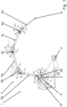
- FIG. 1 shows schematically a large manipulator 1 designed as a truck-mounted concrete pump with a chassis 2 on which a turntable 3 is arranged, which can be rotated about a vertical axis 16 of the large manipulator 1 by means of a hydraulic rotary drive 6.
- An articulated mast 4, designated overall by the reference number 4 is articulated to the turntable 3, which in the embodiment shown comprises four mast segments 5a, 5b, 5c and 5d.
- the first mast segment 5a is attached to the turntable 3 via a joint so that it can pivot about a horizontal axis.
- the pivoting movement is effected by a pivot drive 6a.
- the other mast segments 5b, 5c and 5d are connected to the adjacent mast segments 5a, 5b, 5c, 5d via articulated joints so that they can pivot about mutually parallel horizontal axes.
- the swivel movement is also effected by a swivel drive 6a, 6b, 6c, 6d.
- the swivel drives 6a, 6b, 6c, 6d each have one (or more) hydraulic cylinders which are controlled via proportional control valves 8 ( Fig. 2a, 2b , 3 ) These in turn are controlled by an electronic control device 7 ( Fig.3 ) for the mast movement.
- the large manipulator 1 has a mast sensor system (e.g. in the form of angle sensors for the joints, displacement sensors for detecting the piston positions of the individual hydraulic cylinders or geodetic inclination sensors).
- a mast sensor system e.g. in the form of angle sensors for the joints, displacement sensors for detecting the piston positions of the individual hydraulic cylinders or geodetic inclination sensors.
- the control device 7 Fig.3
- the control valves 8 Fig. 2a, 2b , 3
- the hydraulic cylinder controls the speed of the mast movement depending on the current swivel angles ⁇ 1 , ⁇ 2 , ⁇ 3 and ⁇ 4 of the articulated joints.
- a control device 7 ( Fig.3 ) is designed to control the mast movement of the articulated mast 4.
- the position of at least one point of the articulated mast 4 or a swivel angle ⁇ 1, ⁇ 2, ⁇ 3, ⁇ 4 of at least one articulated joint is detected in normal operation via the mast sensor system.
- the speed of the mast movement is controlled by the control device 7 ( Fig.3 ) depending on the current output signals of the mast sensors. This is done in particular by limiting the travel speed of at least one of the drives 6, 6a, 6b, 6c 6d to a variable maximum value that depends on the current output signals of the mast sensors.
- the drives 6, 6a, 6b, 6c, 6d can be controlled manually.
- at least one limiting means 11, 12, 13, 14 is provided which limits the travel speed of at least one of the drives 6, 6a, 6b, 6c, 6d to a fixed maximum value.
- the Figure 2a shows schematically a control valve 8, which is connected to the hydraulic working lines 9b, 10b for controlling a drive 6, 6a, 6b, 6c, 6d ( Fig.1 ) is connected to each of the drives 6, 6a, 6b, 6c, 6d ( Fig.1 ) is assigned its own control valve 8.
- the control valve 8 is connected to a hydraulic pump (not shown) via the hydraulic working lines 9a, 10a, which provides the hydraulic pressure or the necessary hydraulic fluid volume required for moving the articulated mast.
- the drive 6, 6a, 6b, 6c, 6d ( Fig.1 ) is supplied with hydraulic pressure via the hydraulic working lines 9b, 10b from the control valve 8, so that the drive 6a, 6b, 6c, 6d ( Fig.1 ) the mast segments 5a, 5b, 5c, 5d ( Fig.1 ) are pivoted against each other via the articulated joint or the drive 6 causes a rotary movement of the articulated mast 4.
- the control valve 8 is controlled in normal operation via the control device 7 ( Fig.3 ) to effect the mast movement of the articulated mast 4 by actuating the valve piston 18 by means of the valve piston control device 18a.
- the electronic control of the control valve 8 can be carried out as in Fig.3 shown, via a variable voltage signal or, for example, via an electronic digital signal.
- the Control device 7 limits the adjustment of the mast segment 5a, 5b, 5c, 5d ( Fig.1 ) in the articulated joint or in the turntable 3 in such a way that the speed of the mast movement is limited depending on the current output signals of the mast sensors. This is done in particular by limiting the travel speed of the drive 6, 6a, 6b, 6c 6d ( Fig.1 ) is limited to a variable maximum value that depends on the current output signals of the mast sensors. In this way, the control device 7 ( Fig.3 ) limit the speed of the mast movement so that a specified mast speed is not exceeded.
- the drive 6, 6a, 6b, 6c, 6d can be controlled manually via the control valve 8 in emergency operation.
- the hand lever that is not attached does not contact the stops 12, 13 in normal operation, so that the travel S of the control valve 8 is not mechanically limited here.
- the control valve 8 can be adjusted over the full piston travel. This results in unhindered control of the valve piston 18 of the control valve 8 via the electronic or hydraulic valve piston actuation device 18a by the control device 7 ( Fig.3 ) for adjusting the mast segment 5a, 5b, 5c, 5d ( Fig.1 ) in normal operation.
- the base 17 can be pivoted by approximately 80 degrees, which is indicated by the dashed outline, while the limitation in emergency operation (not according to the invention) by the stops 12, 13 on the link allows a pivot angle of the hand lever 11 of approximately 40 degrees.
- emergency operation not according to the invention
- the electronic or hydraulic valve piston actuation device 18a is inoperative.
- emergency operation for example, only one control valve 8 for the drives 6, 6a, 6b, 6c, 6d can be controlled with a single hand lever, so that simultaneous movement of several drives 6, 6a, 6b, 6c, 6d is not possible.
- the limitation is designed such that the maximum permissible mast movement speed is not possible when controlling a drive 6, 6a, 6b, 6c, 6d.
- the control valve 8 shown can be a 4/3-way proportional valve with which the hydraulic cylinder is controlled directly.
- the control valve 8 can also be designed as a pilot or pre-control valve for controlling a 4/3-way proportional valve.
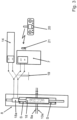
- a control valve 8 designed as a proportional valve is shown.
- the travel S of the valve piston 18 is indicated by the two vertical arrows.
- the adjustment of the valve piston 18 on the travel S is carried out via the electrical valve piston actuating device 18a.
- the valve piston actuating device 18a is controlled in normal operation via the control device 7, the travel commands from the user of the large manipulator 1 ( Fig.1 ) by means of the remote control 20 and the receiver 21.
- a means for electronically limiting the travel S is provided in the emergency mode not according to the invention. This allows the travel speed of the drive 6, 6a, 6b, 6c, 6d ( Fig.1 ) to a fixed maximum value.
- the electrical limitation is ensured by an emergency control 14 used in emergency operation.
- This emergency control 14 provides a reduced electrical voltage for controlling the valve piston actuating device 18a compared to that provided by the control device 7 in normal operation.
- the reduced voltage of the emergency control 14 limits the travel S of the control valve 8 in emergency operation, so that the travel speed of the drive 6, 6a, 6b, 6c, 6d ( Fig.1 ) is limited to a fixed maximum value.
- the control device 7 provides a voltage between -9 V and +9 V for controlling the control valve 8, so that the valve piston 18 can be moved over the full piston travel by the valve piston actuating device 18a.
- a changeover switch 19 is provided for switching between normal operation and emergency operation not according to the invention.
- the actuation of this changeover switch 19 results in the articulated mast 4 ( Fig.1 ) in emergency operation not according to the invention via the electrical emergency control.
- the emergency control 14 provides a fixed reduced voltage of, for example, +4 V and -4 V for controlling the control valve 8 via the valve piston actuation device 18a, whereby the travel of the control valve 8 is correspondingly shortened.
- the voltage of the emergency control for controlling the control valves 8 can also be regulated from -4 V to +4 V. In this way, it can be ensured that the travel speed of the drive 6, 6a, 6b, 6c, 6d ( Fig.1 ) is limited to a fixed maximum value in emergency operation.
- the control valve 8 shown can be a 4/3-way proportional valve with which the hydraulic cylinder is controlled directly. However, the control valve 8 can also be designed as a pilot or pre-control valve for controlling a 4/3-way proportional valve.
- the limitation can, for example, be designed in such a way that the maximum permissible speed of the mast movement is not exceeded when several of the drives 6, 6a, 6b, 6c, 6d are moved simultaneously.
- the elastic deformation of the individual boom segments 5a, 5b, 5c, 5d is neglected, so that these are considered as rigid bodies.
- the absolute movements of the system are in the Inertial coordinate system 0 0 x 0 y 0 z 0 , i.e. described in the coordinate system fixed with respect to the chassis 2.
- O d x d y d z d refers to the coordinate system which is rotated by the angle of rotation ⁇ with respect to the inertial coordinate system.
- a local coordinate system 0 i x i y i z i is defined for each mast segment 5a, 5b, 5c, 5d, the x i axis of which runs along the longitudinal axis of the respective mast segment 5a, 5b, 5c, 5d.
- each local coordinate system is therefore placed at the intersection point of the longitudinal axis with the orthogonal straight line which runs through the joint axis.
- the kinematic relationships between the local coordinate systems and the inertial coordinate system can be represented with rotation matrices and translation vectors.
- R 0 i R 0 d R d 1 R 1 2 ...
- R i ⁇ 1 i with R 0 d cos ⁇ 0 ⁇ sin ⁇ 0 1 0 sin ⁇ 0 cos ⁇
- R d 1 cos ⁇ 1 ⁇ sin ⁇ 1 0 sin ⁇ 1 cos ⁇ 1 0 0 0 1
- N describes the rotation of the local coordinate system 0 i x i y i z i with respect to the inertial coordinate system 0 0 x 0 y 0 z 0 .
- the hydraulic systems used in combination with the control device enable the operator of the large manipulator according to the invention to proportionally control the travel speeds of the individual hydraulic cylinders 6a, 6b, 6c, 6d and the rotary drive 6.
- the resulting joint angle speeds can be determined based on the target speeds for the hydraulic cylinders 6a, 6b, 6c, 6d if the ratio of the joint kinematics is known.
- the use of a suitable mast sensor is required.
- the control device controls the rotary drive 6 and the hydraulic cylinders 6a, 6b, 6c, 6d in accordance with this modified travel command and limits their movement speed so that the mast tip EP never moves faster than legally permitted.
- the travel speed can be as fast as possible within the legal framework, which means that considerable time can be saved when unfolding and folding the articulated mast 4, but also when moving the mast between two working positions, compared to the state of the art.
Landscapes
- Engineering & Computer Science (AREA)
- Architecture (AREA)
- Mechanical Engineering (AREA)
- Civil Engineering (AREA)
- Structural Engineering (AREA)
- Physics & Mathematics (AREA)
- Fluid Mechanics (AREA)
- General Engineering & Computer Science (AREA)
- Chemical & Material Sciences (AREA)
- Analytical Chemistry (AREA)
- Manipulator (AREA)
- On-Site Construction Work That Accompanies The Preparation And Application Of Concrete (AREA)
Claims (4)
- Manipulateur de grande taille (1), en particulier pompe à béton automotrice, avec un chariot de rotation (3) pouvant tourner au moyen d'un entraînement en rotation (6) autour d'un axe vertical, qui est disposé sur un châssis (2), un mât articulé (4), qui comprend deux segments de mât (5a, 5b, 5c, 5d) ou plus, dans lequel les segments de mât (5a, 5b, 5c, 5d) sont reliés de manière mobile par pivotement au moyen de respectivement un entraînement (6a, 6b, 6c, 6d) au chariot de rotation (3) ou au segment de mât (5a, 5b, 5c, 5d) respectivement adjacent par l'intermédiaire d'articulations, avec un dispositif de commande (7) pilotant les entraînements (6, 6a, 6b, 6c, 6d) dans un mode de fonctionnement normal pour le déplacement de mât, et un système de détection servant à détecter la position d'au moins un point du mât articulé (4) ou un angle de pivotement (ϕ1, ϕ2, ϕ3, ϕ4) d'au moins une articulation, dans lequel le dispositif de commande (7) est mis au point pour limiter la vitesse du déplacement de mât en fonction des signaux de sortie instantanés du système de détection de mât, et une soupape de commande (8), laquelle est reliée à des conduites de travail (9b, 10b) hydrauliques d'un entraînement (6, 6a, 6b, 6c, 6d) aux fins de son pilotage, dans lequel la soupape de commande (8) est pilotée dans le mode de fonctionnement normal par l'intermédiaire du dispositif de commande (7), lequel limite l'ajustement du segment de mât (5, 5a, 5b, 5c) de telle manière qu'une vitesse de déplacement prédéfinie n'est pas dépassée,
caractérisé en ce
que les entraînements (6, 6a, 6b, 6c, 6d) peuvent être commandés manuellement dans un mode de fonctionnement d'urgence, dans lequel est prévu au moins un moyen de limitation (11, 12, 13, 14), qui limite dans le mode de fonctionnement d'urgence la vitesse de déplacement d'au moins un des entraînements (6, 6a, 6b, 6c, 6d) à une valeur maximale prédéfinie de manière fixe, le moyen de limitation étant conçu comme le moyen de limitation étant conçu comme une soupape d'urgence montée en parallèle avec la soupape de commande (8), la soupape d'urgence présentant des leviers manuels actionnables pour la commande en fonctionnement d'urgence. - Manipulateur de grande taille (1) selon la revendication 1, caractérisé en ce que la soupape d'urgence prévoit une limitation du débit.
- Manipulateur de grande taille (1) selon la revendication 1 ou 2, caractérisé en ce qu'est prévue une autre soupape à avance rapide commutée en parallèle de la soupape de commande (8) et/ou de la soupape d'urgence, laquelle est fournie pour un ajustement rapide du segment de mât (5a, 5b, 5c, 5d).
- Procédé de commande du déplacement d'un mât articulé (4) d'un manipulateur de grande taille (1), en particulier d'une pompe à béton automotrice, dans lequel le mât articulé (4) comprend deux segments de mât (5, 5a, 5b, 5c) ou plus, les segments de mât (5, 5a, 5b, 5c) sont reliés de manière mobile par pivotement au moyen de respectivement un entraînement (6, 6a, 6b, 6c) au chariot de rotation (3) ou segment de mât (5, 5a, 5b, 5c) respectivement adjacent par l'intermédiaire d'articulations, dans lequel l'angle de pivotement (ϕ1, ϕ2, ϕ3, ϕ4) d'au moins une articulation du mât articulé (4) ou la position d'au moins un point du mât articulé (4) sont détectés par un système de détection, dans lequel la vitesse du déplacement de mât est limitée dans un mode de fonctionnement normal en fonction des signaux de sortie instantanés du système de détection de mât,
caractérisé en ce
que les entraînements individuels (6, 6a, 6b, 6c) des articulations sont commandés proportionnellement en fonctionnement normal selon une commande d'entraînement, dans laquelle la commande d'entraînement spécifie les vitesses cibles des entraînements (6, 6a, 6b, 6c, 6d), la vitesse de la pointe (EP) du mât articulé (4) résultant de la commande d'entraînement, des longueurs des segments de mât et du signal de sortie du système de détection de mât est déterminée, les spécifications de vitesse des différents entraînements (6, 6a, 6b, 6c, 6d) étant réduites par rapport à la commande d'entraînement, dès que la commande d'entraînement amènerait à ce que la vitesse de la pointe (EP) du mât articulé (4) dépasse une valeur seuil prédéterminée, la vitesse de tous les entraînements (6, 6a, 6b, 6c, 6d) étant réduite du même facteur par rapport à la commande d'entraînement, de sorte que la vitesse de la pointe (EP) du mât articulé (4) soit toujours inférieure ou égale à la valeur seuil prédéterminée, c'est-à-dire indépendante de la position actuelle du mât, qui résulte des angles de pivotement (ϕ1, ϕ2, ϕ3, ϕ4) détectés par les capteurs des articulations, dans laquelle la vitesse du déplacement de mât est limitée dans un mode de fonctionnement d'urgence en ce que la vitesse de déplacement d'au moins un des entraînements (6, 6a, 6b, 6c, 6d) est limitée à une valeur maximale prédéfinie de manière fixe.
Applications Claiming Priority (2)
| Application Number | Priority Date | Filing Date | Title |
|---|---|---|---|
| DE102016123160.6A DE102016123160A1 (de) | 2016-11-30 | 2016-11-30 | Großmanipulator mit schnell ein- und ausfaltbarem Knickmast |
| PCT/EP2017/081006 WO2018100074A2 (fr) | 2016-11-30 | 2017-11-30 | Manipulateur de grande taille muni d'un mât articulé rapidement repliable et déployable |
Publications (3)
| Publication Number | Publication Date |
|---|---|
| EP3548752A2 EP3548752A2 (fr) | 2019-10-09 |
| EP3548752B1 EP3548752B1 (fr) | 2021-01-06 |
| EP3548752B2 true EP3548752B2 (fr) | 2024-09-25 |
Family
ID=61627044
Family Applications (1)
| Application Number | Title | Priority Date | Filing Date |
|---|---|---|---|
| EP17849899.4A Active EP3548752B2 (fr) | 2016-11-30 | 2017-11-30 | Manipulateur de grande taille muni d'un mât articulé rapidement repliable et déployable |
Country Status (6)
| Country | Link |
|---|---|
| US (1) | US11098491B2 (fr) |
| EP (1) | EP3548752B2 (fr) |
| KR (1) | KR102428384B1 (fr) |
| CN (1) | CN110199128B (fr) |
| DE (1) | DE102016123160A1 (fr) |
| WO (1) | WO2018100074A2 (fr) |
Families Citing this family (7)
| Publication number | Priority date | Publication date | Assignee | Title |
|---|---|---|---|---|
| DE102016125145A1 (de) * | 2016-12-21 | 2018-06-21 | Schwing Gmbh | Großmanipulator mit automatisiertem Mastaufbau |
| AT520543B1 (de) * | 2018-01-23 | 2019-05-15 | Schwing Gmbh F | Großmanipulator mit Endschlauchhalter |
| DE102019201182A1 (de) * | 2019-01-30 | 2020-07-30 | Putzmeister Engineering Gmbh | Fahrzeug |
| DE102019129810A1 (de) * | 2019-11-05 | 2021-05-06 | Putzmeister Engineering Gmbh | Verfahren, Steuereinrichtung, System, Betonverteilermast und Computerprogramm zum Steuern der Bewegung eines Endschlauchs |
| DE102021107140A1 (de) | 2021-03-23 | 2022-09-29 | Putzmeister Engineering Gmbh | Ausfallsichere Standsicherheitsüberwachung für ein Dickstofffördersystem |
| US20230151624A1 (en) | 2021-11-12 | 2023-05-18 | EZ Placer, LLC | Mobile concrete distribution system |
| CN114753640B (zh) * | 2022-04-01 | 2023-04-07 | 中联重科股份有限公司 | 臂架末端运动规划方法、装置、控制系统及工程机械 |
Citations (9)
| Publication number | Priority date | Publication date | Assignee | Title |
|---|---|---|---|---|
| US4759183A (en) † | 1985-12-30 | 1988-07-26 | Mannesmann Rexroth Gmbh | Control arrangement for at least two hydraulic loads fed by at least one pump |
| EP2347988A1 (fr) † | 2010-01-26 | 2011-07-27 | Cifa S.P.A. | Dispositif pour contrôler activement les vibrations d'un bras articulé pour pomper du béton. |
| EP2500584A1 (fr) † | 2009-11-10 | 2012-09-19 | Hunan Sany Intelligent Control Equipment Co., Ltd | Vanne à voies multiples, dispositif hydraulique et véhicule de pompe à béton |
| JP2013091931A (ja) † | 2011-10-24 | 2013-05-16 | Kyokuto Kaihatsu Kogyo Co Ltd | コンクリートポンプ車 |
| WO2014165888A1 (fr) † | 2013-04-09 | 2014-10-16 | Ttcontrol Gmbh | Circuit de commande électrohydraulique |
| WO2014165889A1 (fr) † | 2013-04-09 | 2014-10-16 | Ttcontrol Gmbh | Système de régulation et procédé de commande de l'orientation d'un segment d'un manipulateur |
| CN204284052U (zh) † | 2014-11-11 | 2015-04-22 | 博世力士乐(北京)液压有限公司 | 用于液压阀的电动行程限制器以及相应的液压泵 |
| EP3015625A1 (fr) † | 2014-10-31 | 2016-05-04 | CIFA SpA | Procédé et appareil pour déplacer un bras articulé |
| EP3088782A1 (fr) † | 2015-04-29 | 2016-11-02 | HAWE Hydraulik SE | Vanne de commande hydraulique en construction à coulisse et installation hydraulique mobile dotée d'une vanne de commande correspondante |
Family Cites Families (13)
| Publication number | Priority date | Publication date | Assignee | Title |
|---|---|---|---|---|
| DE8335902U1 (de) * | 1983-12-14 | 1987-06-04 | Brueninghaus Hydraulik Gmbh, 7240 Horb | Drehmomenten-Regeleinrichtung für eine verstellbare Hydropumpe |
| DE4223695C2 (de) * | 1992-07-21 | 1994-12-08 | Weber Anlagenbau Gmbh & Co Kg | Steuerung für das Verschwenken eines in seiner effektiven Länge veränderlichen Auslegers |
| JP2001226081A (ja) * | 2000-02-16 | 2001-08-21 | Tadano Ltd | 屈伸ブーム式作業車のブーム作動速度制御装置 |
| DE10107107A1 (de) * | 2001-02-14 | 2002-08-29 | Putzmeister Ag | Vorrichtung zur Betätigung eines Knickmasts eines Großmanipulators sowie Großmanipulator mit einer solchen Vorrichtung |
| CN100591880C (zh) * | 2006-12-31 | 2010-02-24 | 三一重工股份有限公司 | 一种智能臂架控制装置 |
| JP5591459B2 (ja) * | 2008-09-26 | 2014-09-17 | 株式会社アイチコーポレーション | ブーム作業車のノンストップ作動制御装置 |
| JP5816517B2 (ja) * | 2011-10-24 | 2015-11-18 | 極東開発工業株式会社 | コンクリートポンプ車 |
| JP5926027B2 (ja) * | 2011-10-24 | 2016-05-25 | 極東開発工業株式会社 | コンクリートポンプ車 |
| JP5751141B2 (ja) * | 2011-11-10 | 2015-07-22 | 株式会社デンソー | 電磁制御装置 |
| ITMI20120362A1 (it) * | 2012-03-07 | 2013-09-08 | Cifa Spa | Procedimento per il controllo delle vibrazioni di un braccio articolato e relativo apparato |
| DE202013012536U1 (de) * | 2013-04-11 | 2017-05-18 | Liebherr-Betonpumpen Gmbh | Fahrbares Arbeitsgerät mit drehbarem Mast oder Ausleger |
| DE102013014626B4 (de) * | 2013-09-04 | 2022-09-08 | Schwing Gmbh | Bestimmung der Position eines verlagerbaren Messpunktes an einer Maschine |
| CN205603095U (zh) * | 2016-02-23 | 2016-09-28 | 成都凯天电子股份有限公司 | 机务工作吊车 |
-
2016
- 2016-11-30 DE DE102016123160.6A patent/DE102016123160A1/de active Pending
-
2017
- 2017-11-30 US US16/464,554 patent/US11098491B2/en active Active
- 2017-11-30 CN CN201780083508.4A patent/CN110199128B/zh active Active
- 2017-11-30 WO PCT/EP2017/081006 patent/WO2018100074A2/fr not_active Ceased
- 2017-11-30 KR KR1020197018860A patent/KR102428384B1/ko active Active
- 2017-11-30 EP EP17849899.4A patent/EP3548752B2/fr active Active
Patent Citations (9)
| Publication number | Priority date | Publication date | Assignee | Title |
|---|---|---|---|---|
| US4759183A (en) † | 1985-12-30 | 1988-07-26 | Mannesmann Rexroth Gmbh | Control arrangement for at least two hydraulic loads fed by at least one pump |
| EP2500584A1 (fr) † | 2009-11-10 | 2012-09-19 | Hunan Sany Intelligent Control Equipment Co., Ltd | Vanne à voies multiples, dispositif hydraulique et véhicule de pompe à béton |
| EP2347988A1 (fr) † | 2010-01-26 | 2011-07-27 | Cifa S.P.A. | Dispositif pour contrôler activement les vibrations d'un bras articulé pour pomper du béton. |
| JP2013091931A (ja) † | 2011-10-24 | 2013-05-16 | Kyokuto Kaihatsu Kogyo Co Ltd | コンクリートポンプ車 |
| WO2014165888A1 (fr) † | 2013-04-09 | 2014-10-16 | Ttcontrol Gmbh | Circuit de commande électrohydraulique |
| WO2014165889A1 (fr) † | 2013-04-09 | 2014-10-16 | Ttcontrol Gmbh | Système de régulation et procédé de commande de l'orientation d'un segment d'un manipulateur |
| EP3015625A1 (fr) † | 2014-10-31 | 2016-05-04 | CIFA SpA | Procédé et appareil pour déplacer un bras articulé |
| CN204284052U (zh) † | 2014-11-11 | 2015-04-22 | 博世力士乐(北京)液压有限公司 | 用于液压阀的电动行程限制器以及相应的液压泵 |
| EP3088782A1 (fr) † | 2015-04-29 | 2016-11-02 | HAWE Hydraulik SE | Vanne de commande hydraulique en construction à coulisse et installation hydraulique mobile dotée d'une vanne de commande correspondante |
Non-Patent Citations (1)
| Title |
|---|
| HARTMUT BENCKERT: "Mechydronic® für die Maststeuerung von Autobetonpumpen Zusammenwirken von Mechanik, Hydraulik und Elektronik", WISSENSPORTAL BAUMASCHINE, 2004, pages 1 - 12 † |
Also Published As
| Publication number | Publication date |
|---|---|
| WO2018100074A2 (fr) | 2018-06-07 |
| US20200392747A1 (en) | 2020-12-17 |
| KR20190089047A (ko) | 2019-07-29 |
| DE102016123160A1 (de) | 2018-05-30 |
| EP3548752A2 (fr) | 2019-10-09 |
| US11098491B2 (en) | 2021-08-24 |
| CN110199128A (zh) | 2019-09-03 |
| KR102428384B1 (ko) | 2022-08-03 |
| CN110199128B (zh) | 2021-02-19 |
| EP3548752B1 (fr) | 2021-01-06 |
| WO2018100074A3 (fr) | 2018-07-26 |
Similar Documents
| Publication | Publication Date | Title |
|---|---|---|
| EP3548752B2 (fr) | Manipulateur de grande taille muni d'un mât articulé rapidement repliable et déployable | |
| EP3303732B1 (fr) | Manipulateur de grande taille présentant un mât articulé rapidement repliable et déployable | |
| EP2186405B1 (fr) | Tige de pulvérisation et son procédé de commande | |
| EP1980441B1 (fr) | Levier de commande pour un véhicule | |
| DE102013014138B3 (de) | Lenkanschlag | |
| EP1426499A1 (fr) | Procédé et appareil d'amortissement des fins de course d'un cylindre hydraulique utilisé dans des engins de travaux publics | |
| EP2899318B1 (fr) | Engin automobile de construction routière, en particulier compresseur et procédé de conduite d'un engin de construction routière | |
| EP3797588A1 (fr) | Procédé de commande et/ou de réglage de mouvement d'un dispositif d'épandage agricole | |
| DE102004029409A1 (de) | Druckmittelbetätigte Stelleinrichtung, insbesondere für eine Fahrzeuglenkvorrichtung | |
| DE10000110B4 (de) | Hydrostatischer Fahrzeugantrieb mit Steuerungseinrichtung und Steuerungseinrichtung für hydrostatische Antriebe | |
| EP0217408A2 (fr) | Procédé et dispositif pour le réglage en hauteur d'une poutre lisseuse | |
| EP2332682A1 (fr) | Procédé de commande d'un dispositif de montage hydraulique et dispositif de montage hydraulique, notamment pour la rupture, le broyage ou le recyclage | |
| DE102013221468A1 (de) | Motorisch faltbares Spritzgestänge sowie Verfahren zum motorischen Ein- und Ausklappen eines solchen Spritzgestänges | |
| EP3743574B1 (fr) | Manipulateur de grande taille avec support d'un tuyau d'extremite | |
| DE102017104814A1 (de) | Steuer- und/oder Regelsystem, landwirtschaftliches Nutzfahrzeug und Verfahren zur Steuerung und/oder Regelung eines landwirtschaftlichen Nutzfahrzeugs | |
| EP3372077A1 (fr) | Système de règlage pour une machine agricole | |
| DE202008005035U1 (de) | Arbeitsgerät und Notablasssystem | |
| DE3104072A1 (de) | "vorrichtung zur parallelachsigen kinematischen steuerung eines hebemaschinen-auslegers" | |
| EP3957808A1 (fr) | Manipulateur de grand taille muni d'un système hydraulique décentralisé | |
| WO2012156085A1 (fr) | Procédé d'un dispositif de réglage électro-hydraulique d'un mécanisme de levage et unité de commande pour un dispositif de réglage électro-hydraulique d'un mécanisme de levage | |
| EP3737474B1 (fr) | Procédé permettant de faire fonctionner un outil de travail ou un appareil de sauvetage, outil de travail ou appareil de sauvetage | |
| EP4335981B1 (fr) | Machine de construction pourvu de système hydraulique | |
| EP4345036B1 (fr) | Dispositif de préhension d'une structure plate avec des ouvertures dans la zone supérieure | |
| DE102021121163A1 (de) | Verbesserter Teleskoplader | |
| DE102018207676A1 (de) | Bedieneinrichtung |
Legal Events
| Date | Code | Title | Description |
|---|---|---|---|
| STAA | Information on the status of an ep patent application or granted ep patent |
Free format text: STATUS: UNKNOWN |
|
| STAA | Information on the status of an ep patent application or granted ep patent |
Free format text: STATUS: THE INTERNATIONAL PUBLICATION HAS BEEN MADE |
|
| PUAI | Public reference made under article 153(3) epc to a published international application that has entered the european phase |
Free format text: ORIGINAL CODE: 0009012 |
|
| STAA | Information on the status of an ep patent application or granted ep patent |
Free format text: STATUS: REQUEST FOR EXAMINATION WAS MADE |
|
| 17P | Request for examination filed |
Effective date: 20190701 |
|
| AK | Designated contracting states |
Kind code of ref document: A2 Designated state(s): AL AT BE BG CH CY CZ DE DK EE ES FI FR GB GR HR HU IE IS IT LI LT LU LV MC MK MT NL NO PL PT RO RS SE SI SK SM TR |
|
| AX | Request for extension of the european patent |
Extension state: BA ME |
|
| DAV | Request for validation of the european patent (deleted) | ||
| DAX | Request for extension of the european patent (deleted) | ||
| GRAP | Despatch of communication of intention to grant a patent |
Free format text: ORIGINAL CODE: EPIDOSNIGR1 |
|
| STAA | Information on the status of an ep patent application or granted ep patent |
Free format text: STATUS: GRANT OF PATENT IS INTENDED |
|
| INTG | Intention to grant announced |
Effective date: 20200717 |
|
| GRAS | Grant fee paid |
Free format text: ORIGINAL CODE: EPIDOSNIGR3 |
|
| GRAA | (expected) grant |
Free format text: ORIGINAL CODE: 0009210 |
|
| STAA | Information on the status of an ep patent application or granted ep patent |
Free format text: STATUS: THE PATENT HAS BEEN GRANTED |
|
| AK | Designated contracting states |
Kind code of ref document: B1 Designated state(s): AL AT BE BG CH CY CZ DE DK EE ES FI FR GB GR HR HU IE IS IT LI LT LU LV MC MK MT NL NO PL PT RO RS SE SI SK SM TR |
|
| REG | Reference to a national code |
Ref country code: GB Ref legal event code: FG4D Free format text: NOT ENGLISH |
|
| RIN1 | Information on inventor provided before grant (corrected) |
Inventor name: LEHMANN,ANDREAS Inventor name: HENIKL, JOHANNES Inventor name: VIERKOTTEN, REINER Inventor name: SCHNITTKER, JOSEPH |
|
| REG | Reference to a national code |
Ref country code: AT Ref legal event code: REF Ref document number: 1352681 Country of ref document: AT Kind code of ref document: T Effective date: 20210115 Ref country code: CH Ref legal event code: EP |
|
| REG | Reference to a national code |
Ref country code: DE Ref legal event code: R096 Ref document number: 502017009018 Country of ref document: DE |
|
| REG | Reference to a national code |
Ref country code: IE Ref legal event code: FG4D Free format text: LANGUAGE OF EP DOCUMENT: GERMAN |
|
| REG | Reference to a national code |
Ref country code: NL Ref legal event code: MP Effective date: 20210106 |
|
| REG | Reference to a national code |
Ref country code: LT Ref legal event code: MG9D |
|
| PG25 | Lapsed in a contracting state [announced via postgrant information from national office to epo] |
Ref country code: BG Free format text: LAPSE BECAUSE OF FAILURE TO SUBMIT A TRANSLATION OF THE DESCRIPTION OR TO PAY THE FEE WITHIN THE PRESCRIBED TIME-LIMIT Effective date: 20210406 Ref country code: LT Free format text: LAPSE BECAUSE OF FAILURE TO SUBMIT A TRANSLATION OF THE DESCRIPTION OR TO PAY THE FEE WITHIN THE PRESCRIBED TIME-LIMIT Effective date: 20210106 Ref country code: HR Free format text: LAPSE BECAUSE OF FAILURE TO SUBMIT A TRANSLATION OF THE DESCRIPTION OR TO PAY THE FEE WITHIN THE PRESCRIBED TIME-LIMIT Effective date: 20210106 Ref country code: FI Free format text: LAPSE BECAUSE OF FAILURE TO SUBMIT A TRANSLATION OF THE DESCRIPTION OR TO PAY THE FEE WITHIN THE PRESCRIBED TIME-LIMIT Effective date: 20210106 Ref country code: GR Free format text: LAPSE BECAUSE OF FAILURE TO SUBMIT A TRANSLATION OF THE DESCRIPTION OR TO PAY THE FEE WITHIN THE PRESCRIBED TIME-LIMIT Effective date: 20210407 Ref country code: PT Free format text: LAPSE BECAUSE OF FAILURE TO SUBMIT A TRANSLATION OF THE DESCRIPTION OR TO PAY THE FEE WITHIN THE PRESCRIBED TIME-LIMIT Effective date: 20210506 Ref country code: NO Free format text: LAPSE BECAUSE OF FAILURE TO SUBMIT A TRANSLATION OF THE DESCRIPTION OR TO PAY THE FEE WITHIN THE PRESCRIBED TIME-LIMIT Effective date: 20210406 |
|
| PG25 | Lapsed in a contracting state [announced via postgrant information from national office to epo] |
Ref country code: SE Free format text: LAPSE BECAUSE OF FAILURE TO SUBMIT A TRANSLATION OF THE DESCRIPTION OR TO PAY THE FEE WITHIN THE PRESCRIBED TIME-LIMIT Effective date: 20210106 Ref country code: PL Free format text: LAPSE BECAUSE OF FAILURE TO SUBMIT A TRANSLATION OF THE DESCRIPTION OR TO PAY THE FEE WITHIN THE PRESCRIBED TIME-LIMIT Effective date: 20210106 Ref country code: LV Free format text: LAPSE BECAUSE OF FAILURE TO SUBMIT A TRANSLATION OF THE DESCRIPTION OR TO PAY THE FEE WITHIN THE PRESCRIBED TIME-LIMIT Effective date: 20210106 Ref country code: RS Free format text: LAPSE BECAUSE OF FAILURE TO SUBMIT A TRANSLATION OF THE DESCRIPTION OR TO PAY THE FEE WITHIN THE PRESCRIBED TIME-LIMIT Effective date: 20210106 |
|
| PG25 | Lapsed in a contracting state [announced via postgrant information from national office to epo] |
Ref country code: IS Free format text: LAPSE BECAUSE OF FAILURE TO SUBMIT A TRANSLATION OF THE DESCRIPTION OR TO PAY THE FEE WITHIN THE PRESCRIBED TIME-LIMIT Effective date: 20210506 |
|
| REG | Reference to a national code |
Ref country code: DE Ref legal event code: R026 Ref document number: 502017009018 Country of ref document: DE |
|
| PLBI | Opposition filed |
Free format text: ORIGINAL CODE: 0009260 |
|
| PLAX | Notice of opposition and request to file observation + time limit sent |
Free format text: ORIGINAL CODE: EPIDOSNOBS2 |
|
| PG25 | Lapsed in a contracting state [announced via postgrant information from national office to epo] |
Ref country code: EE Free format text: LAPSE BECAUSE OF FAILURE TO SUBMIT A TRANSLATION OF THE DESCRIPTION OR TO PAY THE FEE WITHIN THE PRESCRIBED TIME-LIMIT Effective date: 20210106 Ref country code: CZ Free format text: LAPSE BECAUSE OF FAILURE TO SUBMIT A TRANSLATION OF THE DESCRIPTION OR TO PAY THE FEE WITHIN THE PRESCRIBED TIME-LIMIT Effective date: 20210106 Ref country code: SM Free format text: LAPSE BECAUSE OF FAILURE TO SUBMIT A TRANSLATION OF THE DESCRIPTION OR TO PAY THE FEE WITHIN THE PRESCRIBED TIME-LIMIT Effective date: 20210106 |
|
| 26 | Opposition filed |
Opponent name: PUTZMEISTER ENGINEERING GMBH Effective date: 20211006 Opponent name: HAWE HYDRAULIK SE Effective date: 20211004 |
|
| PG25 | Lapsed in a contracting state [announced via postgrant information from national office to epo] |
Ref country code: RO Free format text: LAPSE BECAUSE OF FAILURE TO SUBMIT A TRANSLATION OF THE DESCRIPTION OR TO PAY THE FEE WITHIN THE PRESCRIBED TIME-LIMIT Effective date: 20210106 Ref country code: SK Free format text: LAPSE BECAUSE OF FAILURE TO SUBMIT A TRANSLATION OF THE DESCRIPTION OR TO PAY THE FEE WITHIN THE PRESCRIBED TIME-LIMIT Effective date: 20210106 Ref country code: DK Free format text: LAPSE BECAUSE OF FAILURE TO SUBMIT A TRANSLATION OF THE DESCRIPTION OR TO PAY THE FEE WITHIN THE PRESCRIBED TIME-LIMIT Effective date: 20210106 |
|
| PG25 | Lapsed in a contracting state [announced via postgrant information from national office to epo] |
Ref country code: AL Free format text: LAPSE BECAUSE OF FAILURE TO SUBMIT A TRANSLATION OF THE DESCRIPTION OR TO PAY THE FEE WITHIN THE PRESCRIBED TIME-LIMIT Effective date: 20210106 Ref country code: ES Free format text: LAPSE BECAUSE OF FAILURE TO SUBMIT A TRANSLATION OF THE DESCRIPTION OR TO PAY THE FEE WITHIN THE PRESCRIBED TIME-LIMIT Effective date: 20210106 |
|
| PG25 | Lapsed in a contracting state [announced via postgrant information from national office to epo] |
Ref country code: SI Free format text: LAPSE BECAUSE OF FAILURE TO SUBMIT A TRANSLATION OF THE DESCRIPTION OR TO PAY THE FEE WITHIN THE PRESCRIBED TIME-LIMIT Effective date: 20210106 |
|
| PLBB | Reply of patent proprietor to notice(s) of opposition received |
Free format text: ORIGINAL CODE: EPIDOSNOBS3 |
|
| PG25 | Lapsed in a contracting state [announced via postgrant information from national office to epo] |
Ref country code: IS Free format text: LAPSE BECAUSE OF FAILURE TO SUBMIT A TRANSLATION OF THE DESCRIPTION OR TO PAY THE FEE WITHIN THE PRESCRIBED TIME-LIMIT Effective date: 20210506 |
|
| PG25 | Lapsed in a contracting state [announced via postgrant information from national office to epo] |
Ref country code: MC Free format text: LAPSE BECAUSE OF FAILURE TO SUBMIT A TRANSLATION OF THE DESCRIPTION OR TO PAY THE FEE WITHIN THE PRESCRIBED TIME-LIMIT Effective date: 20210106 |
|
| REG | Reference to a national code |
Ref country code: CH Ref legal event code: PL |
|
| PG25 | Lapsed in a contracting state [announced via postgrant information from national office to epo] |
Ref country code: LU Free format text: LAPSE BECAUSE OF NON-PAYMENT OF DUE FEES Effective date: 20211130 Ref country code: BE Free format text: LAPSE BECAUSE OF NON-PAYMENT OF DUE FEES Effective date: 20211130 |
|
| REG | Reference to a national code |
Ref country code: BE Ref legal event code: MM Effective date: 20211130 |
|
| PG25 | Lapsed in a contracting state [announced via postgrant information from national office to epo] |
Ref country code: LI Free format text: LAPSE BECAUSE OF NON-PAYMENT OF DUE FEES Effective date: 20211130 Ref country code: CH Free format text: LAPSE BECAUSE OF NON-PAYMENT OF DUE FEES Effective date: 20211130 |
|
| PG25 | Lapsed in a contracting state [announced via postgrant information from national office to epo] |
Ref country code: IE Free format text: LAPSE BECAUSE OF NON-PAYMENT OF DUE FEES Effective date: 20211130 |
|
| PLAY | Examination report in opposition despatched + time limit |
Free format text: ORIGINAL CODE: EPIDOSNORE2 |
|
| PLBC | Reply to examination report in opposition received |
Free format text: ORIGINAL CODE: EPIDOSNORE3 |
|
| PG25 | Lapsed in a contracting state [announced via postgrant information from national office to epo] |
Ref country code: NL Free format text: LAPSE BECAUSE OF NON-PAYMENT OF DUE FEES Effective date: 20210206 Ref country code: CY Free format text: LAPSE BECAUSE OF FAILURE TO SUBMIT A TRANSLATION OF THE DESCRIPTION OR TO PAY THE FEE WITHIN THE PRESCRIBED TIME-LIMIT Effective date: 20210106 |
|
| PG25 | Lapsed in a contracting state [announced via postgrant information from national office to epo] |
Ref country code: HU Free format text: LAPSE BECAUSE OF FAILURE TO SUBMIT A TRANSLATION OF THE DESCRIPTION OR TO PAY THE FEE WITHIN THE PRESCRIBED TIME-LIMIT; INVALID AB INITIO Effective date: 20171130 |
|
| PLAY | Examination report in opposition despatched + time limit |
Free format text: ORIGINAL CODE: EPIDOSNORE2 |
|
| P01 | Opt-out of the competence of the unified patent court (upc) registered |
Effective date: 20231108 |
|
| REG | Reference to a national code |
Ref country code: AT Ref legal event code: MM01 Ref document number: 1352681 Country of ref document: AT Kind code of ref document: T Effective date: 20221130 |
|
| PG25 | Lapsed in a contracting state [announced via postgrant information from national office to epo] |
Ref country code: AT Free format text: LAPSE BECAUSE OF NON-PAYMENT OF DUE FEES Effective date: 20221130 |
|
| APBM | Appeal reference recorded |
Free format text: ORIGINAL CODE: EPIDOSNREFNO |
|
| APBP | Date of receipt of notice of appeal recorded |
Free format text: ORIGINAL CODE: EPIDOSNNOA2O |
|
| APAH | Appeal reference modified |
Free format text: ORIGINAL CODE: EPIDOSCREFNO |
|
| PG25 | Lapsed in a contracting state [announced via postgrant information from national office to epo] |
Ref country code: MK Free format text: LAPSE BECAUSE OF FAILURE TO SUBMIT A TRANSLATION OF THE DESCRIPTION OR TO PAY THE FEE WITHIN THE PRESCRIBED TIME-LIMIT Effective date: 20210106 |
|
| APBU | Appeal procedure closed |
Free format text: ORIGINAL CODE: EPIDOSNNOA9O |
|
| PG25 | Lapsed in a contracting state [announced via postgrant information from national office to epo] |
Ref country code: TR Free format text: LAPSE BECAUSE OF FAILURE TO SUBMIT A TRANSLATION OF THE DESCRIPTION OR TO PAY THE FEE WITHIN THE PRESCRIBED TIME-LIMIT Effective date: 20210106 |
|
| PUAH | Patent maintained in amended form |
Free format text: ORIGINAL CODE: 0009272 |
|
| STAA | Information on the status of an ep patent application or granted ep patent |
Free format text: STATUS: PATENT MAINTAINED AS AMENDED |
|
| 27A | Patent maintained in amended form |
Effective date: 20240925 |
|
| AK | Designated contracting states |
Kind code of ref document: B2 Designated state(s): AL AT BE BG CH CY CZ DE DK EE ES FI FR GB GR HR HU IE IS IT LI LT LU LV MC MK MT NL NO PL PT RO RS SE SI SK SM TR |
|
| REG | Reference to a national code |
Ref country code: DE Ref legal event code: R102 Ref document number: 502017009018 Country of ref document: DE |
|
| PG25 | Lapsed in a contracting state [announced via postgrant information from national office to epo] |
Ref country code: MT Free format text: LAPSE BECAUSE OF FAILURE TO SUBMIT A TRANSLATION OF THE DESCRIPTION OR TO PAY THE FEE WITHIN THE PRESCRIBED TIME-LIMIT Effective date: 20210106 |
|
| PGFP | Annual fee paid to national office [announced via postgrant information from national office to epo] |
Ref country code: DE Payment date: 20241128 Year of fee payment: 8 |
|
| PGFP | Annual fee paid to national office [announced via postgrant information from national office to epo] |
Ref country code: GB Payment date: 20241126 Year of fee payment: 8 |
|
| PGFP | Annual fee paid to national office [announced via postgrant information from national office to epo] |
Ref country code: FR Payment date: 20241126 Year of fee payment: 8 |
|
| PGFP | Annual fee paid to national office [announced via postgrant information from national office to epo] |
Ref country code: IT Payment date: 20241125 Year of fee payment: 8 |