EP3548358B1 - Verfahren zur notabschaltung einer versorgungsspannung oder fahrstromversorgung auf einer elektrifizierten strecke oder einem elektrifizierten streckenabschnitt für schienenfahrzeuge - Google Patents
Verfahren zur notabschaltung einer versorgungsspannung oder fahrstromversorgung auf einer elektrifizierten strecke oder einem elektrifizierten streckenabschnitt für schienenfahrzeuge Download PDFInfo
- Publication number
- EP3548358B1 EP3548358B1 EP17804194.3A EP17804194A EP3548358B1 EP 3548358 B1 EP3548358 B1 EP 3548358B1 EP 17804194 A EP17804194 A EP 17804194A EP 3548358 B1 EP3548358 B1 EP 3548358B1
- Authority
- EP
- European Patent Office
- Prior art keywords
- signal
- rail vehicle
- power supply
- line
- supply voltage
- Prior art date
- Legal status (The legal status is an assumption and is not a legal conclusion. Google has not performed a legal analysis and makes no representation as to the accuracy of the status listed.)
- Active
Links
Images
Classifications
-
- B—PERFORMING OPERATIONS; TRANSPORTING
- B60—VEHICLES IN GENERAL
- B60M—POWER SUPPLY LINES, AND DEVICES ALONG RAILS, FOR ELECTRICALLY- PROPELLED VEHICLES
- B60M3/00—Feeding power to supply lines in contact with collector on vehicles; Arrangements for consuming regenerative power
- B60M3/04—Arrangements for cutting in and out of individual track sections
-
- B—PERFORMING OPERATIONS; TRANSPORTING
- B61—RAILWAYS
- B61L—GUIDING RAILWAY TRAFFIC; ENSURING THE SAFETY OF RAILWAY TRAFFIC
- B61L23/00—Control, warning or like safety means along the route or between vehicles or trains
-
- B—PERFORMING OPERATIONS; TRANSPORTING
- B61—RAILWAYS
- B61L—GUIDING RAILWAY TRAFFIC; ENSURING THE SAFETY OF RAILWAY TRAFFIC
- B61L25/00—Recording or indicating positions or identities of vehicles or trains or setting of track apparatus
- B61L25/02—Indicating or recording positions or identities of vehicles or trains
- B61L25/025—Absolute localisation, e.g. providing geodetic coordinates
-
- B—PERFORMING OPERATIONS; TRANSPORTING
- B61—RAILWAYS
- B61L—GUIDING RAILWAY TRAFFIC; ENSURING THE SAFETY OF RAILWAY TRAFFIC
- B61L27/00—Central railway traffic control systems; Trackside control; Communication systems specially adapted therefor
- B61L27/50—Trackside diagnosis or maintenance, e.g. software upgrades
- B61L27/53—Trackside diagnosis or maintenance, e.g. software upgrades for trackside elements or systems, e.g. trackside supervision of trackside control system conditions
Definitions
- the invention relates to a method for emergency shutdown of a supply voltage or traction power supply on an electrified route or an electrified route section for rail vehicles, a rail vehicle with an emergency signal transmission device for the emergency shutdown of a supply voltage or traction power supply on an electrified route or an electrified route section for the rail vehicle and a system for Emergency shutdown of a supply voltage or traction power supply on an electrified route or an electrified route section for rail vehicles.
- Rail vehicles are usually powered by electricity. This can be done directly via busbars or overhead lines, whereby the circuit is closed again via the rails.
- the DE19544158A1 describes a device for emergency call and position transmission from a vehicle to a central control center. It enables modes of transport to determine the exact position of a vehicle, particularly in the area of passenger transport, or to exchange data between the vehicle and a central control center.
- the position is determined using satellite positioning (GPS) and comparing the on-board computer data and is transmitted to a central control center via company radio or GSM. There, the data is evaluated in a master computer.
- GPS satellite positioning
- This system can only transmit an emergency message to a central control center.
- an interruption in the power supply to the rail vehicle can be advantageous.
- short circuits can occur at system separation points from power systems of the traction power supply that separate one another if the power supply is not interrupted at these points.
- the EP2266834A1 describes a control system and method that stores the geographic location of neutral sections on board the vehicle.
- a GPS system on the vehicle determines the geographic location of the vehicle.
- a control system program determines the position of the vehicle relative to the position of the neutral portion from the memory of the GPS. It also includes a controller to keep the line break of the vehicle open as long as the pantograph passes the neutral section.
- the feed of the rail current into the rail vehicle can thus be interrupted depending on the position of the vehicle on the route.
- the power supply in the overhead line remains.
- the DE602004001036T2 describes a supply system for an overhead line, with a plurality of supply stations for the overhead line, each supply station being connected between two sections of the overhead line which are in front of and behind it in the direction of travel, and each supply station in response to control signals for interrupting the supply to at least one of the Sections of the overhead line in the direction of travel in front of and behind it is suitable, to which it is connected.
- the system has at least one generator suitable for transmitting the control signals by means of the overhead line, and each station has a receiver which is used to receive the control signals transmitted by means of the overhead line and to control the interruption of the supply of at least one of the sections of the overhead line Answer to the at least one of these control signals is suitable.
- the traction power supply is controlled via control signals on the overhead line.
- the traction power supply cannot be switched off in the event of an emergency. If the connection to the overhead line breaks off, such as if the overhead line breaks, the power supply can no longer be switched off.
- the DE 3626960 A1 discloses a switch-off device for traction current lines for vehicles guided in a guidance route.
- the invention provides that two bare wires that are not in contact with one another run along the guidance route within arm's reach of the vehicle driver and that lead to a centrally arranged, fixed relay for switching off the power lines lead and to which a voltage source installed in the vehicle can be temporarily connected via a flexible cable.
- the EP 2 305 534 A1 discloses an arrangement and a method for a driverless means of transport for activating a safe operating state, the path of the driverless means of transport comprising a plurality of path segments and the operating element or the sensor being assigned to at least one of the path segments.
- a message for activating the safe operating state is transmitted from the control element or the sensor to a digital control of the driverless means of transport, the digital control using a redundant position detection system the position of the driverless means of transport present at the time the message is processed or at that time by the path segment traveled by the driverless means of transport is recorded and compared with the location information available for the message to be processed and, if there is a match, the safe operating state for the driverless means of transport is activated.
- the object of the invention is therefore to provide an improved possibility of switching off the supply voltage or traction current supply on an electrified route or on an electrified route section for rail vehicles.
- the invention can be used in particular for systems with overhead lines or for systems with busbars.
- An advantage of the invention is the possibility of a quick emergency shutdown of the supply voltage or traction power supply on electrified routes or route sections directly on site from the rail vehicle or by rescue workers.
- rescue workers can also switch off the supply voltage or traction power supply from outside when the driver is no longer able to do so.
- the sender can receive reliable information when the supply voltage or traction power supply is switched off and rescue or maintenance work can be started.
- the signal can be transmitted via GSM. This has the advantage that already known communication channels can be used. This is particularly advantageous for sending the signal from an external, mobile transmission device, such as for the fire service, the police, or other rescue workers.
- the signal is preferably transmitted via radio.
- the signal can in particular be transmitted via Global System for Mobile Communications (GSM).
- GSM Global System for Mobile Communications
- the signal is sent from the rail vehicle, this can be implemented by a transmission device in the vehicle.
- the transmission device can be connected to a vehicle controller or be part of it.
- the signal is sent by an external, mobile transmission device, this can be implemented by a radio or by a cell phone.
- Any device suitable for receiving the transmitted signal is suitable as the receiving device.
- the information about the sender can include information about the operator, the transmitting device and / or the rail vehicle.
- the identification data of the rail vehicle are preferably sent, with which the latter can be identified.
- identification data or identification data are sent from a mobile transmitter.
- the operators in particular the vehicle driver, members of the on-board personnel, the maintenance personnel, the fire brigade, the police, the THW or other rescue workers come into consideration.
- the mobile transmission device can be operated from outside the rail vehicle, for example by fire services or auxiliary personnel.
- an operating point is to be understood as the point which is responsible and authorized to switch off, switch on a supply voltage or traction current supply.
- An operating point can be a (route) control center.
- Communication with the operating point can be indirect, for example via intermediate points, depending on the structure of a communication network in the rail infrastructure. For example, communication can be established directly with an infeed station, which in turn then informs the operating station, in particular a control center.
- the current position of the rail vehicle is particularly used to denote a geographical position, for example in latitude and longitude.
- position data can be determined in a rail vehicle using a position determination system, preferably a global position system (GPS).
- a position determination system preferably a global position system (GPS).
- data can be determined using a wheel sensor or displacement encoder.
- the geographic position can be determined by coupling data from the wheel sensor or path encoder with the GPS data determined last. Such a method is described in DE19544158A1 .
- the geographic position is determined by coupling the GPS data with data from the speed calculation of the rail vehicle.
- the current position can also be determined by the external, mobile transmission device, or in the case of such a transmission device, via a position determination system, preferably GPS.
- the signal is preferably generated and sent as a data telegram.
- the supply voltage or traction power supply can be switched off on the route or on the route section in the operating point.
- the supply voltage or traction power supply is preferably switched off on the route section on which the rail vehicle is located.
- An embodiment of the invention relates to a method, wherein the rail vehicle has an operating element for a driver of the rail vehicle and a signal generating device which is coupled to the operating element, and the method further comprises actuating the control element and generating the signal in the signal generating device.
- the control element can be a touch element, for example a switch, a button or a lever, preferably it is a specially marked or illuminated switch.
- the probe element is particularly preferably provided with a protective cover in order to avoid undesired actuation.
- control element is located in the driver's station, in particular in the control panel of the rail vehicle.
- the signal generating device is the vehicle controller or is integrated in the vehicle controller.
- Another embodiment of the invention relates to a method in which the mobile transmission device has a computer program application, and the method further comprises actuating the computer program application and generating the signal by the computer program application.
- the mobile transmission device can be a radio or a mobile phone, with the operator actuating the computer program application manually.
- the signal or data telegram can be sent with this application.
- the configured transmitter and location information are compiled and sent in a data telegram in the mobile transmission device.
- a manual mode can also be selected in the application of the mobile transmission device, in which the section to be switched off can be selected.
- the computer program application can be, in particular, an Android application or application for Apple devices, or a Windows application.
- the method comprises checking the signal in an operating center for the sender's authorization.
- all authorized transmitters or mobile external transmission devices can be registered with the receiving device, for example with identification data that can be transmitted during the communication. In this case, only a signal from a registered or authorized transmission device leads to an emergency shutdown of the supply voltage or traction power supply on the route or the route section.
- the signal can be encrypted or otherwise secured.
- the method comprises sending an acknowledgment signal from the operating point to the sender, which contains information about the shutdown of the supply voltage or traction power supply.
- a route control or an operating point can thus send a signal, preferably a data telegram, back to the sender or the mobile transmission device so that the sender receives the information that the route is switched off and secured.
- the sender in particular a vehicle driver or operator of the rescue workers, can receive feedback from the operating point and can be informed whether the overhead line is switched off. For this purpose, a secure signal from the operating point to the vehicle can be sent to the sender, in particular a driver or operator of the rescue workers. The information can be safely displayed to the sender.
- the display can be done on a mobile device.
- the fire brigade, police, rescue workers or maintenance personnel can read out the status and start any measures or work, or the train driver or the on-board personnel are informed of a possible shutdown of the route or section of the route.
- a further embodiment variant of the invention relates to a method which has the transmission of an information signal from the operating point to at least one further rail vehicle located on the route, which contains information about the switching off of the supply voltage or traction current supply.
- the receiving device is arranged on the route. There may be several reception facilities along the route be, preferably at defined intervals. One or more receiving devices can be assigned to a route section.
- the supply voltage or traction power supply can be switched off automatically in the operating point.
- a person for example a driving service provider, to switch off, that is to say switch off manually, in the operating point.
- an automatic shutdown takes place, as mentioned.
- An advantage of the invention is that an emergency call can be made by a vehicle driver with position information and rescue measures can be accelerated.
- the signal can also contain information about the current position of the rail vehicle.
- the signal mentioned can be generated automatically when the control element is actuated. No further action by the operator is therefore required.
- What is not meant by the invention is a radio announcement in the form of a radio signal, in which an operator verbally transmits the information mentioned.
- the control element can be a touch element, for example a switch, a button or a lever, preferably it is an illuminated switch.
- the probe element is particularly preferably provided with a protective cover in order to avoid undesired actuation.
- the control element can be designed on a touch-sensitive display (touchscreen, softkey). These examples are not limitative.
- control element is located in the driver's station, in particular in the control panel of the rail vehicle.
- the signal generating device is the vehicle controller or is integrated in the vehicle controller.
- the signal is preferably transmitted via radio or GSM.
- the information about the sender can include information about the operator and / or the rail vehicle. Identification data of the rail vehicle are preferably sent, with which the latter can be identified.
- the current position of the rail vehicle indicates the geographical position.
- the rail vehicle can be equipped with one or more position determination systems.
- the rail vehicle is preferably equipped with a global position system (GPS) and the GPS data can be transmitted.
- GPS global position system
- the rail vehicle is additionally equipped with a wheel sensor or travel pulse generator and connected to an on-board computer in order to determine the geographical position by coupling the wheel sensor data with the GPS data in the absence of satellite reception.
- the geographic position is obtained by coupling the GPS data with data from the speed calculation of the rail vehicle determined. This is preferably done in addition, since GPS is not continuously available.
- the invention also relates to a system for the emergency shutdown of a supply voltage or traction power supply on an electrified route or an electrified route section for rail vehicles, comprising the rail vehicle according to the invention or a mobile transmission device external to the rail vehicle, which is set up to generate a signal that provides information for the desired switching off of the supply voltage or traction power supply on the route or the route section, contains information about the sender and information about the current position of the mobile transmitting device and at least one receiving device from which the signal can be received and forwarded to an operating point.
- the external mobile transmission device can be a radio or a mobile telephone, in particular a smartphone, or a tablet PC. These examples are also not restrictive.
- the external mobile transmission device is preferably equipped with a position determination system, preferably GPS.
- the mobile transmission device has a computer program application.
- the signal preferably a data telegram, in particular a secured data telegram, can be generated by actuating the radio or the computer program application.
- the operator can operate the computer program application manually. Furthermore, the state or status of the current or voltage feed can be queried or displayed.
- the configured transmitter and location information are compiled and sent in a data telegram in the mobile transmission device.
- a manual mode can also be selected in the application of the mobile transmission device, in which the section to be switched off can be selected.
- the information about the sender can include the information about the operator, the transmitting device and / or the rail vehicle. If possible, the identification data of the rail vehicle can be sent, with which it can be identified. Members of the fire brigade, maintenance personnel, the police, the THW or other rescue workers are particularly considered as operating personnel.
- the system has a checking of the signal in the operating center for the sender's authorization. Permissions can be granted to users to provide access protection.
- a transmitting device and / or a receiving device preferably have access protection, in particular with secured user authorization queries.
- the mobile external transmitting devices can be registered with the receiving device.
- the receiving device is arranged on the route.
- a system is particularly preferred in which a plurality of receiving devices are arranged along the route.
- One or more of the receiving devices can preferably be assigned to a route section.
- a receiving device is also arranged spatially on an assigned route section.
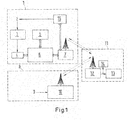
- infrastructure with line feed 11 shows the procedural steps that take place after the signal is sent and are the same for the variant of the emergency shutdown from the rail vehicle 1 and for the variant of the emergency shutdown from an external mobile transmission device 10.
- the vehicle driver 2 actuates an operating element 3, here a button, which is provided with a protective cover.
- the button can have lighting that can be used to indicate the status, i.e. whether the button was pressed or not.
- the signal is then sent to the digital input / output module 4 and from the signal in the signal generating device 6, here the vehicle control (VCU), and With the GPS data from the position determination system 5, a data telegram is generated which contains information about the position of the rail vehicle 1, the identification data of the rail vehicle 1 and the identity of the sender, in this case the driver 2.
- the driver is the operator here.
- the element to be identified is vehicle number X on line Y with driver Z.
- This data telegram is forwarded via a transmitter 7 by radio or GSM to the receiving device 12, which is attached on the track side.
- the mobile external transmission device 10 which in this example is a GSM mobile radio device with GPS receiver and remote Shutdown application represents, manually activated by a member of the rescue workers or maintenance personnel 9.
- the signal is forwarded to the receiving device 12 by radio or GSM.
- the signal is transmitted to the operating point 14 by the receiving device 12 so that the dispatcher can be informed, and from there the voltage on the route or the route section is switched off via the route main switch 13.
- an automated shutdown is provided. If the control of the power supply is carried out with devices that are also provided or suitable for manual operation, for example with a main line switch 13 that can be operated by hand, an electrical control of the switching operations of the line feed can be provided for automation of the shutdown.
- a line main switch 13 can be controlled with an electrical control, which is also referred to as line main switch control (not shown in the figures).
- line main switch control not shown in the figures.
- another type of shutdown can be provided, which can no longer be operated manually.
- a signal is then sent back to the transmitter 7 of the rail vehicle or the external mobile transmission device 10, with the information that the Route is de-energized.
- a status display 15 is provided, preferably as a display on the control panel, so that the operator receives information about the status of the voltage or the travel current.
Landscapes
- Engineering & Computer Science (AREA)
- Mechanical Engineering (AREA)
- Health & Medical Sciences (AREA)
- Biomedical Technology (AREA)
- General Health & Medical Sciences (AREA)
- Train Traffic Observation, Control, And Security (AREA)
- Electric Propulsion And Braking For Vehicles (AREA)
- Alarm Systems (AREA)
Priority Applications (1)
| Application Number | Priority Date | Filing Date | Title |
|---|---|---|---|
| PL17804194T PL3548358T3 (pl) | 2016-11-29 | 2017-11-27 | Sposób wyłączenia awaryjnego napięcia zasilającego lub prądu trakcyjnego zasilającego pojazd szynowy na zelektryfikowanej linii kolejowej lub zelektryfikowanym odcinku linii kolejowej |
Applications Claiming Priority (2)
| Application Number | Priority Date | Filing Date | Title |
|---|---|---|---|
| DE102016223623.7A DE102016223623A1 (de) | 2016-11-29 | 2016-11-29 | Verfahren zur Notabschaltung |
| PCT/EP2017/080514 WO2018099857A1 (de) | 2016-11-29 | 2017-11-27 | Verfahren zur notabschaltung einer versorgungsspannung oder fahrstromversorgung auf einer elektrifizierten strecke oder einem elektrifizierten streckenabschnitt für schienenfahrzeuge |
Publications (2)
| Publication Number | Publication Date |
|---|---|
| EP3548358A1 EP3548358A1 (de) | 2019-10-09 |
| EP3548358B1 true EP3548358B1 (de) | 2020-07-15 |
Family
ID=60452670
Family Applications (1)
| Application Number | Title | Priority Date | Filing Date |
|---|---|---|---|
| EP17804194.3A Active EP3548358B1 (de) | 2016-11-29 | 2017-11-27 | Verfahren zur notabschaltung einer versorgungsspannung oder fahrstromversorgung auf einer elektrifizierten strecke oder einem elektrifizierten streckenabschnitt für schienenfahrzeuge |
Country Status (7)
| Country | Link |
|---|---|
| EP (1) | EP3548358B1 (pl) |
| CN (1) | CN110035942B (pl) |
| DE (1) | DE102016223623A1 (pl) |
| ES (1) | ES2824817T3 (pl) |
| PL (1) | PL3548358T3 (pl) |
| RU (1) | RU2742843C2 (pl) |
| WO (1) | WO2018099857A1 (pl) |
Cited By (1)
| Publication number | Priority date | Publication date | Assignee | Title |
|---|---|---|---|---|
| RU2813359C1 (ru) * | 2022-11-03 | 2024-02-12 | Федеральное государственное бюджетное научное учреждение "Федеральный научный агроинженерный центр ВИМ" (ФГБНУ ФНАЦ ВИМ) | Способ резервирования электроснабжения потребителей, подключенных к секционированной линии электропередачи, с применением мобильных энергетических платформ |
Families Citing this family (4)
| Publication number | Priority date | Publication date | Assignee | Title |
|---|---|---|---|---|
| CN109693689B (zh) * | 2018-12-21 | 2021-05-25 | 株洲中车机电科技有限公司 | 一种用于牵引切断的安全控制系统及方法 |
| DE102019001382B3 (de) | 2019-02-26 | 2020-07-23 | Michael Nold | Bedarfsgerechte dynamische speiseabschnittsbasierte Fahrleitungskurzschlusserkennungssteuerung für Schienenfahrwege und Schienenfahrzeuge |
| CN113173110B (zh) * | 2021-04-23 | 2023-02-17 | 重庆中车长客轨道车辆有限公司 | 双流制车辆无电区切换失败应急系统 |
| CN113183832B (zh) * | 2021-05-18 | 2022-08-12 | 中铁二院工程集团有限责任公司 | 一种电气化铁路功率平衡协同柔性过分相装置及控制方法 |
Family Cites Families (11)
| Publication number | Priority date | Publication date | Assignee | Title |
|---|---|---|---|---|
| DE3626960A1 (de) * | 1986-08-08 | 1988-02-18 | Daimler Benz Ag | Abschaltvorrichtung fuer fahrstromleitungen fuer in einer spurfuehrungstrasse spurgefuehrte fahrzeuge |
| DE19544158A1 (de) | 1995-11-14 | 1997-05-15 | Neskom Gmbh | Fahrgastnotruf- und Satellitenortungssystem |
| FR2864480B1 (fr) | 2003-12-31 | 2006-03-24 | Alstom | Systeme et station d'alimentation d'une catenaire, et procede d'interruption de cette alimentation |
| US7340329B2 (en) | 2004-11-24 | 2008-03-04 | New York Air Brake Corporation | System and method for controlling an electrified vehicle |
| EP2305534B1 (de) * | 2009-09-30 | 2015-07-29 | Siemens Aktiengesellschaft | Anordnung und Verfahren zur Aktivierung eines sicheren Betriebszustandes für ein fahrerloses Transportmittel |
| DE102010002694A1 (de) * | 2010-03-09 | 2011-09-15 | Siemens Aktiengesellschaft | Kontrollsystem und Kontrollverfahren für Stromversorgungstrennstellen |
| DE102011103951C5 (de) * | 2011-06-07 | 2014-11-27 | Fraunhofer-Gesellschaft zur Förderung der angewandten Forschung e.V. | Sensoranordnung zur Feststellung von Unregelmäßigkeiten in oder an einer Fahrstromleitung für schienengebundene Fahrzeuge |
| JP2013141891A (ja) * | 2012-01-11 | 2013-07-22 | Hitachi Ltd | き電を用いた鉄道信号システム |
| DE102013210018A1 (de) * | 2013-05-29 | 2014-12-04 | Siemens Aktiengesellschaft | Verfahren zum Ein- und Ausschalten eines Zuges sowie Strecken- und Zugkonfiguration zur Durchführung des Verfahrens |
| DE102013219647A1 (de) * | 2013-09-27 | 2015-04-16 | Siemens Aktiengesellschaft | Betrieb eines Schienenfahrzeugs |
| DE102015204105A1 (de) * | 2015-03-06 | 2016-09-08 | Siemens Aktiengesellschaft | Anordnung und Verfahren für eine Stromversorgung einer Fahrleitung |
-
2016
- 2016-11-29 DE DE102016223623.7A patent/DE102016223623A1/de not_active Ceased
-
2017
- 2017-11-27 RU RU2019119416A patent/RU2742843C2/ru active
- 2017-11-27 PL PL17804194T patent/PL3548358T3/pl unknown
- 2017-11-27 EP EP17804194.3A patent/EP3548358B1/de active Active
- 2017-11-27 ES ES17804194T patent/ES2824817T3/es active Active
- 2017-11-27 WO PCT/EP2017/080514 patent/WO2018099857A1/de not_active Ceased
- 2017-11-27 CN CN201780073795.0A patent/CN110035942B/zh active Active
Non-Patent Citations (1)
| Title |
|---|
| None * |
Cited By (1)
| Publication number | Priority date | Publication date | Assignee | Title |
|---|---|---|---|---|
| RU2813359C1 (ru) * | 2022-11-03 | 2024-02-12 | Федеральное государственное бюджетное научное учреждение "Федеральный научный агроинженерный центр ВИМ" (ФГБНУ ФНАЦ ВИМ) | Способ резервирования электроснабжения потребителей, подключенных к секционированной линии электропередачи, с применением мобильных энергетических платформ |
Also Published As
| Publication number | Publication date |
|---|---|
| PL3548358T3 (pl) | 2021-01-25 |
| WO2018099857A1 (de) | 2018-06-07 |
| CN110035942B (zh) | 2021-07-16 |
| RU2019119416A3 (pl) | 2021-01-11 |
| RU2742843C2 (ru) | 2021-02-11 |
| DE102016223623A1 (de) | 2018-05-30 |
| ES2824817T3 (es) | 2021-05-13 |
| RU2019119416A (ru) | 2021-01-11 |
| CN110035942A (zh) | 2019-07-19 |
| EP3548358A1 (de) | 2019-10-09 |
Similar Documents
| Publication | Publication Date | Title |
|---|---|---|
| EP3548358B1 (de) | Verfahren zur notabschaltung einer versorgungsspannung oder fahrstromversorgung auf einer elektrifizierten strecke oder einem elektrifizierten streckenabschnitt für schienenfahrzeuge | |
| EP3593090B1 (de) | Verfahren und einrichtung zum automatisierten fahren mit sicherem haltepunkt | |
| DE19654960A1 (de) | Verfahren und Einrichtung zur gleichmäßigen Lastverteilung in Unterwerken für elektrisch betriebene Fahrzeuge | |
| DE4321348C1 (de) | Verfahren und Vorrichtung zur Früherkennung und Meldung von Fehler- und Gefahrenquellen in schienengebundenen und schienenlosen Fahrzeugen des öffentlichen Nahverkehrs | |
| EP1391365B1 (de) | Elektronische Deichsel | |
| EP3036146B1 (de) | Betrieb eines schienenfahrzeugs | |
| EP4067199B1 (de) | Verfahren zum evakuieren von passagieren aus einem fahrzeug, endgerät und fahrzeug für dieses verfahren | |
| EP3400160A1 (de) | Bahntechnische anlage und verfahren zum betreiben einer bahntechnischen anlage | |
| WO2022156959A1 (de) | Verfahren zum bereitstellen einer eine hochvoltbatterie eines kraftfahrzeugs betreffenden zustandsinformation und bereitstellungseinrichtung | |
| DE102018222002A1 (de) | Verfahren und elektronisches Fahrzeugführungssystem zur Fernsteuerung eines fahrerlos fahrenden Kraftfahrzeugs | |
| EP1944215B1 (de) | Verfahren zum Umstellen einer Weiche | |
| EP4124540A1 (de) | Verfahren und vorrichtung betreiben einer fahrsperre für ein spurgebundenes fahrzeug | |
| EP0286627B1 (de) | Einrichtung zum Warnen von Rotten | |
| EP3092162A1 (de) | Verfahren zum steuern eines mit einem cbtc-system verbundenen schienenfahrzeugs und cbtc-system mit mindestens einem schienenfahrzeug | |
| EP3943363B1 (de) | Eisenbahnleitsystem mit bedienhemmung | |
| DE102016200796B4 (de) | Verfahren zur Ansteuerung einer Anzeigevorrichtung eines Kraftfahrzeugs und Kraftfahrzeug | |
| EP3823878B1 (de) | Verfahren und system zum betreiben eines spurgebundenen fahrzeugs in einem von einer begleitperson begleiteten fahrerlosen betrieb | |
| EP3786025A1 (de) | Autonome bahnschrankenanlage für eine etcs-eisenbahnstrecke | |
| WO2017045863A1 (de) | Kommunikationseinrichtung und verfahren zum automatisierten austausch von nachrichten in einer eisenbahntechnischen anlage | |
| DE102016218469A1 (de) | Verfahren und Vorrichtung zur Sicherung einer eisenbahntechnischen Anlage | |
| DE19715773A1 (de) | Verfahren zur Sicherung eines Zugleitbetriebes eines Schienennetzes und Sicherungsgerät zur Durchführung dieses Verfahrens | |
| DE102023207143A1 (de) | Manuell-teleoperierter Wechsel-Betrieb eines Transportfahrzeugs | |
| DE102024129189A1 (de) | Verfahren und Informationssystem zum Bereitstellen von Warninformationen in einem Informationssystem | |
| DE102015226729A1 (de) | Vorrichtung zur Generierung und Übertragung eines automatischen Notrufs und Verfahren für eine automatische Notfall-Meldung | |
| DE102016212914A1 (de) | Verfahren zum Verfolgen eines Leitfahrzeugs durch ein Verfolgungsfahrzeug und Fahrzeug |
Legal Events
| Date | Code | Title | Description |
|---|---|---|---|
| STAA | Information on the status of an ep patent application or granted ep patent |
Free format text: STATUS: UNKNOWN |
|
| STAA | Information on the status of an ep patent application or granted ep patent |
Free format text: STATUS: THE INTERNATIONAL PUBLICATION HAS BEEN MADE |
|
| PUAI | Public reference made under article 153(3) epc to a published international application that has entered the european phase |
Free format text: ORIGINAL CODE: 0009012 |
|
| STAA | Information on the status of an ep patent application or granted ep patent |
Free format text: STATUS: REQUEST FOR EXAMINATION WAS MADE |
|
| 17P | Request for examination filed |
Effective date: 20190624 |
|
| AK | Designated contracting states |
Kind code of ref document: A1 Designated state(s): AL AT BE BG CH CY CZ DE DK EE ES FI FR GB GR HR HU IE IS IT LI LT LU LV MC MK MT NL NO PL PT RO RS SE SI SK SM TR |
|
| AX | Request for extension of the european patent |
Extension state: BA ME |
|
| GRAP | Despatch of communication of intention to grant a patent |
Free format text: ORIGINAL CODE: EPIDOSNIGR1 |
|
| STAA | Information on the status of an ep patent application or granted ep patent |
Free format text: STATUS: GRANT OF PATENT IS INTENDED |
|
| DAV | Request for validation of the european patent (deleted) | ||
| DAX | Request for extension of the european patent (deleted) | ||
| INTG | Intention to grant announced |
Effective date: 20200102 |
|
| GRAS | Grant fee paid |
Free format text: ORIGINAL CODE: EPIDOSNIGR3 |
|
| GRAJ | Information related to disapproval of communication of intention to grant by the applicant or resumption of examination proceedings by the epo deleted |
Free format text: ORIGINAL CODE: EPIDOSDIGR1 |
|
| GRAL | Information related to payment of fee for publishing/printing deleted |
Free format text: ORIGINAL CODE: EPIDOSDIGR3 |
|
| STAA | Information on the status of an ep patent application or granted ep patent |
Free format text: STATUS: REQUEST FOR EXAMINATION WAS MADE |
|
| GRAR | Information related to intention to grant a patent recorded |
Free format text: ORIGINAL CODE: EPIDOSNIGR71 |
|
| STAA | Information on the status of an ep patent application or granted ep patent |
Free format text: STATUS: GRANT OF PATENT IS INTENDED |
|
| INTC | Intention to grant announced (deleted) | ||
| GRAA | (expected) grant |
Free format text: ORIGINAL CODE: 0009210 |
|
| STAA | Information on the status of an ep patent application or granted ep patent |
Free format text: STATUS: THE PATENT HAS BEEN GRANTED |
|
| AK | Designated contracting states |
Kind code of ref document: B1 Designated state(s): AL AT BE BG CH CY CZ DE DK EE ES FI FR GB GR HR HU IE IS IT LI LT LU LV MC MK MT NL NO PL PT RO RS SE SI SK SM TR |
|
| INTG | Intention to grant announced |
Effective date: 20200608 |
|
| REG | Reference to a national code |
Ref country code: CH Ref legal event code: EP Ref country code: GB Ref legal event code: FG4D Free format text: NOT ENGLISH |
|
| REG | Reference to a national code |
Ref country code: IE Ref legal event code: FG4D Free format text: LANGUAGE OF EP DOCUMENT: GERMAN |
|
| REG | Reference to a national code |
Ref country code: DE Ref legal event code: R096 Ref document number: 502017006281 Country of ref document: DE |
|
| REG | Reference to a national code |
Ref country code: AT Ref legal event code: REF Ref document number: 1290724 Country of ref document: AT Kind code of ref document: T Effective date: 20200815 |
|
| REG | Reference to a national code |
Ref country code: CH Ref legal event code: NV Representative=s name: PATENTANWALT DIPL.-ING. (UNI.) WOLFGANG HEISEL, CH |
|
| REG | Reference to a national code |
Ref country code: LT Ref legal event code: MG4D |
|
| REG | Reference to a national code |
Ref country code: NL Ref legal event code: MP Effective date: 20200715 |
|
| PG25 | Lapsed in a contracting state [announced via postgrant information from national office to epo] |
Ref country code: FI Free format text: LAPSE BECAUSE OF FAILURE TO SUBMIT A TRANSLATION OF THE DESCRIPTION OR TO PAY THE FEE WITHIN THE PRESCRIBED TIME-LIMIT Effective date: 20200715 Ref country code: NO Free format text: LAPSE BECAUSE OF FAILURE TO SUBMIT A TRANSLATION OF THE DESCRIPTION OR TO PAY THE FEE WITHIN THE PRESCRIBED TIME-LIMIT Effective date: 20201015 Ref country code: GR Free format text: LAPSE BECAUSE OF FAILURE TO SUBMIT A TRANSLATION OF THE DESCRIPTION OR TO PAY THE FEE WITHIN THE PRESCRIBED TIME-LIMIT Effective date: 20201016 Ref country code: BG Free format text: LAPSE BECAUSE OF FAILURE TO SUBMIT A TRANSLATION OF THE DESCRIPTION OR TO PAY THE FEE WITHIN THE PRESCRIBED TIME-LIMIT Effective date: 20201015 Ref country code: SE Free format text: LAPSE BECAUSE OF FAILURE TO SUBMIT A TRANSLATION OF THE DESCRIPTION OR TO PAY THE FEE WITHIN THE PRESCRIBED TIME-LIMIT Effective date: 20200715 Ref country code: PT Free format text: LAPSE BECAUSE OF FAILURE TO SUBMIT A TRANSLATION OF THE DESCRIPTION OR TO PAY THE FEE WITHIN THE PRESCRIBED TIME-LIMIT Effective date: 20201116 Ref country code: HR Free format text: LAPSE BECAUSE OF FAILURE TO SUBMIT A TRANSLATION OF THE DESCRIPTION OR TO PAY THE FEE WITHIN THE PRESCRIBED TIME-LIMIT Effective date: 20200715 Ref country code: LT Free format text: LAPSE BECAUSE OF FAILURE TO SUBMIT A TRANSLATION OF THE DESCRIPTION OR TO PAY THE FEE WITHIN THE PRESCRIBED TIME-LIMIT Effective date: 20200715 |
|
| PG25 | Lapsed in a contracting state [announced via postgrant information from national office to epo] |
Ref country code: RS Free format text: LAPSE BECAUSE OF FAILURE TO SUBMIT A TRANSLATION OF THE DESCRIPTION OR TO PAY THE FEE WITHIN THE PRESCRIBED TIME-LIMIT Effective date: 20200715 Ref country code: LV Free format text: LAPSE BECAUSE OF FAILURE TO SUBMIT A TRANSLATION OF THE DESCRIPTION OR TO PAY THE FEE WITHIN THE PRESCRIBED TIME-LIMIT Effective date: 20200715 Ref country code: IS Free format text: LAPSE BECAUSE OF FAILURE TO SUBMIT A TRANSLATION OF THE DESCRIPTION OR TO PAY THE FEE WITHIN THE PRESCRIBED TIME-LIMIT Effective date: 20201115 |
|
| PG25 | Lapsed in a contracting state [announced via postgrant information from national office to epo] |
Ref country code: NL Free format text: LAPSE BECAUSE OF FAILURE TO SUBMIT A TRANSLATION OF THE DESCRIPTION OR TO PAY THE FEE WITHIN THE PRESCRIBED TIME-LIMIT Effective date: 20200715 |
|
| REG | Reference to a national code |
Ref country code: DE Ref legal event code: R097 Ref document number: 502017006281 Country of ref document: DE |
|
| PG25 | Lapsed in a contracting state [announced via postgrant information from national office to epo] |
Ref country code: SM Free format text: LAPSE BECAUSE OF FAILURE TO SUBMIT A TRANSLATION OF THE DESCRIPTION OR TO PAY THE FEE WITHIN THE PRESCRIBED TIME-LIMIT Effective date: 20200715 Ref country code: EE Free format text: LAPSE BECAUSE OF FAILURE TO SUBMIT A TRANSLATION OF THE DESCRIPTION OR TO PAY THE FEE WITHIN THE PRESCRIBED TIME-LIMIT Effective date: 20200715 Ref country code: DK Free format text: LAPSE BECAUSE OF FAILURE TO SUBMIT A TRANSLATION OF THE DESCRIPTION OR TO PAY THE FEE WITHIN THE PRESCRIBED TIME-LIMIT Effective date: 20200715 Ref country code: RO Free format text: LAPSE BECAUSE OF FAILURE TO SUBMIT A TRANSLATION OF THE DESCRIPTION OR TO PAY THE FEE WITHIN THE PRESCRIBED TIME-LIMIT Effective date: 20200715 |
|
| REG | Reference to a national code |
Ref country code: ES Ref legal event code: FG2A Ref document number: 2824817 Country of ref document: ES Kind code of ref document: T3 Effective date: 20210513 |
|
| PLBE | No opposition filed within time limit |
Free format text: ORIGINAL CODE: 0009261 |
|
| STAA | Information on the status of an ep patent application or granted ep patent |
Free format text: STATUS: NO OPPOSITION FILED WITHIN TIME LIMIT |
|
| PG25 | Lapsed in a contracting state [announced via postgrant information from national office to epo] |
Ref country code: AL Free format text: LAPSE BECAUSE OF FAILURE TO SUBMIT A TRANSLATION OF THE DESCRIPTION OR TO PAY THE FEE WITHIN THE PRESCRIBED TIME-LIMIT Effective date: 20200715 |
|
| 26N | No opposition filed |
Effective date: 20210416 |
|
| PG25 | Lapsed in a contracting state [announced via postgrant information from national office to epo] |
Ref country code: SK Free format text: LAPSE BECAUSE OF FAILURE TO SUBMIT A TRANSLATION OF THE DESCRIPTION OR TO PAY THE FEE WITHIN THE PRESCRIBED TIME-LIMIT Effective date: 20200715 Ref country code: MC Free format text: LAPSE BECAUSE OF FAILURE TO SUBMIT A TRANSLATION OF THE DESCRIPTION OR TO PAY THE FEE WITHIN THE PRESCRIBED TIME-LIMIT Effective date: 20200715 |
|
| PG25 | Lapsed in a contracting state [announced via postgrant information from national office to epo] |
Ref country code: LU Free format text: LAPSE BECAUSE OF NON-PAYMENT OF DUE FEES Effective date: 20201127 |
|
| REG | Reference to a national code |
Ref country code: BE Ref legal event code: MM Effective date: 20201130 |
|
| PG25 | Lapsed in a contracting state [announced via postgrant information from national office to epo] |
Ref country code: SI Free format text: LAPSE BECAUSE OF FAILURE TO SUBMIT A TRANSLATION OF THE DESCRIPTION OR TO PAY THE FEE WITHIN THE PRESCRIBED TIME-LIMIT Effective date: 20200715 |
|
| PG25 | Lapsed in a contracting state [announced via postgrant information from national office to epo] |
Ref country code: IE Free format text: LAPSE BECAUSE OF NON-PAYMENT OF DUE FEES Effective date: 20201127 |
|
| PG25 | Lapsed in a contracting state [announced via postgrant information from national office to epo] |
Ref country code: TR Free format text: LAPSE BECAUSE OF FAILURE TO SUBMIT A TRANSLATION OF THE DESCRIPTION OR TO PAY THE FEE WITHIN THE PRESCRIBED TIME-LIMIT Effective date: 20200715 Ref country code: MT Free format text: LAPSE BECAUSE OF FAILURE TO SUBMIT A TRANSLATION OF THE DESCRIPTION OR TO PAY THE FEE WITHIN THE PRESCRIBED TIME-LIMIT Effective date: 20200715 Ref country code: CY Free format text: LAPSE BECAUSE OF FAILURE TO SUBMIT A TRANSLATION OF THE DESCRIPTION OR TO PAY THE FEE WITHIN THE PRESCRIBED TIME-LIMIT Effective date: 20200715 |
|
| PG25 | Lapsed in a contracting state [announced via postgrant information from national office to epo] |
Ref country code: MK Free format text: LAPSE BECAUSE OF FAILURE TO SUBMIT A TRANSLATION OF THE DESCRIPTION OR TO PAY THE FEE WITHIN THE PRESCRIBED TIME-LIMIT Effective date: 20200715 |
|
| PG25 | Lapsed in a contracting state [announced via postgrant information from national office to epo] |
Ref country code: BE Free format text: LAPSE BECAUSE OF NON-PAYMENT OF DUE FEES Effective date: 20201130 |
|
| P01 | Opt-out of the competence of the unified patent court (upc) registered |
Effective date: 20230822 |
|
| REG | Reference to a national code |
Ref country code: CH Ref legal event code: U11 Free format text: ST27 STATUS EVENT CODE: U-0-0-U10-U11 (AS PROVIDED BY THE NATIONAL OFFICE) Effective date: 20251201 |
|
| PGFP | Annual fee paid to national office [announced via postgrant information from national office to epo] |
Ref country code: DE Payment date: 20251119 Year of fee payment: 9 |
|
| PGFP | Annual fee paid to national office [announced via postgrant information from national office to epo] |
Ref country code: GB Payment date: 20251121 Year of fee payment: 9 |
|
| PGFP | Annual fee paid to national office [announced via postgrant information from national office to epo] |
Ref country code: AT Payment date: 20251120 Year of fee payment: 9 |
|
| PGFP | Annual fee paid to national office [announced via postgrant information from national office to epo] |
Ref country code: IT Payment date: 20251125 Year of fee payment: 9 |
|
| PGFP | Annual fee paid to national office [announced via postgrant information from national office to epo] |
Ref country code: FR Payment date: 20251126 Year of fee payment: 9 |
|
| PGFP | Annual fee paid to national office [announced via postgrant information from national office to epo] |
Ref country code: CH Payment date: 20251201 Year of fee payment: 9 |
|
| PGFP | Annual fee paid to national office [announced via postgrant information from national office to epo] |
Ref country code: CZ Payment date: 20251120 Year of fee payment: 9 |
|
| PGFP | Annual fee paid to national office [announced via postgrant information from national office to epo] |
Ref country code: PL Payment date: 20251114 Year of fee payment: 9 |
|
| PGFP | Annual fee paid to national office [announced via postgrant information from national office to epo] |
Ref country code: ES Payment date: 20251229 Year of fee payment: 9 |