EP3547676B1 - Dispositif de commande d'affichage de véhicule, système de commande d'affichage de véhicule, procédé de commande d'affichage de véhicule et programme - Google Patents
Dispositif de commande d'affichage de véhicule, système de commande d'affichage de véhicule, procédé de commande d'affichage de véhicule et programme Download PDFInfo
- Publication number
- EP3547676B1 EP3547676B1 EP17898227.8A EP17898227A EP3547676B1 EP 3547676 B1 EP3547676 B1 EP 3547676B1 EP 17898227 A EP17898227 A EP 17898227A EP 3547676 B1 EP3547676 B1 EP 3547676B1
- Authority
- EP
- European Patent Office
- Prior art keywords
- video image
- display
- vehicle
- image data
- imaging range
- Prior art date
- Legal status (The legal status is an assumption and is not a legal conclusion. Google has not performed a legal analysis and makes no representation as to the accuracy of the status listed.)
- Active
Links
- 238000000034 method Methods 0.000 title claims description 25
- 238000003384 imaging method Methods 0.000 claims description 141
- 230000003287 optical effect Effects 0.000 claims description 41
- 238000010586 diagram Methods 0.000 description 46
- 230000008569 process Effects 0.000 description 15
- 239000011521 glass Substances 0.000 description 6
- 230000008859 change Effects 0.000 description 3
- 230000006870 function Effects 0.000 description 3
- 239000004973 liquid crystal related substance Substances 0.000 description 3
- 230000007246 mechanism Effects 0.000 description 2
- 230000008901 benefit Effects 0.000 description 1
- 230000000694 effects Effects 0.000 description 1
- 238000005401 electroluminescence Methods 0.000 description 1
- 238000010191 image analysis Methods 0.000 description 1
- 238000012544 monitoring process Methods 0.000 description 1
- 239000004065 semiconductor Substances 0.000 description 1
Images


Classifications
-
- H—ELECTRICITY
- H04—ELECTRIC COMMUNICATION TECHNIQUE
- H04N—PICTORIAL COMMUNICATION, e.g. TELEVISION
- H04N7/00—Television systems
- H04N7/18—Closed-circuit television [CCTV] systems, i.e. systems in which the video signal is not broadcast
- H04N7/181—Closed-circuit television [CCTV] systems, i.e. systems in which the video signal is not broadcast for receiving images from a plurality of remote sources
-
- B—PERFORMING OPERATIONS; TRANSPORTING
- B60—VEHICLES IN GENERAL
- B60R—VEHICLES, VEHICLE FITTINGS, OR VEHICLE PARTS, NOT OTHERWISE PROVIDED FOR
- B60R11/00—Arrangements for holding or mounting articles, not otherwise provided for
- B60R11/02—Arrangements for holding or mounting articles, not otherwise provided for for radio sets, television sets, telephones, or the like; Arrangement of controls thereof
- B60R11/0264—Arrangements for holding or mounting articles, not otherwise provided for for radio sets, television sets, telephones, or the like; Arrangement of controls thereof for control means
-
- B—PERFORMING OPERATIONS; TRANSPORTING
- B60—VEHICLES IN GENERAL
- B60R—VEHICLES, VEHICLE FITTINGS, OR VEHICLE PARTS, NOT OTHERWISE PROVIDED FOR
- B60R1/00—Optical viewing arrangements; Real-time viewing arrangements for drivers or passengers using optical image capturing systems, e.g. cameras or video systems specially adapted for use in or on vehicles
- B60R1/12—Mirror assemblies combined with other articles, e.g. clocks
-
- B—PERFORMING OPERATIONS; TRANSPORTING
- B60—VEHICLES IN GENERAL
- B60R—VEHICLES, VEHICLE FITTINGS, OR VEHICLE PARTS, NOT OTHERWISE PROVIDED FOR
- B60R1/00—Optical viewing arrangements; Real-time viewing arrangements for drivers or passengers using optical image capturing systems, e.g. cameras or video systems specially adapted for use in or on vehicles
- B60R1/20—Real-time viewing arrangements for drivers or passengers using optical image capturing systems, e.g. cameras or video systems specially adapted for use in or on vehicles
- B60R1/22—Real-time viewing arrangements for drivers or passengers using optical image capturing systems, e.g. cameras or video systems specially adapted for use in or on vehicles for viewing an area outside the vehicle, e.g. the exterior of the vehicle
- B60R1/23—Real-time viewing arrangements for drivers or passengers using optical image capturing systems, e.g. cameras or video systems specially adapted for use in or on vehicles for viewing an area outside the vehicle, e.g. the exterior of the vehicle with a predetermined field of view
- B60R1/26—Real-time viewing arrangements for drivers or passengers using optical image capturing systems, e.g. cameras or video systems specially adapted for use in or on vehicles for viewing an area outside the vehicle, e.g. the exterior of the vehicle with a predetermined field of view to the rear of the vehicle
-
- B—PERFORMING OPERATIONS; TRANSPORTING
- B60—VEHICLES IN GENERAL
- B60R—VEHICLES, VEHICLE FITTINGS, OR VEHICLE PARTS, NOT OTHERWISE PROVIDED FOR
- B60R11/00—Arrangements for holding or mounting articles, not otherwise provided for
- B60R11/02—Arrangements for holding or mounting articles, not otherwise provided for for radio sets, television sets, telephones, or the like; Arrangement of controls thereof
- B60R11/0229—Arrangements for holding or mounting articles, not otherwise provided for for radio sets, television sets, telephones, or the like; Arrangement of controls thereof for displays, e.g. cathodic tubes
- B60R11/0235—Arrangements for holding or mounting articles, not otherwise provided for for radio sets, television sets, telephones, or the like; Arrangement of controls thereof for displays, e.g. cathodic tubes of flat type, e.g. LCD
-
- B—PERFORMING OPERATIONS; TRANSPORTING
- B60—VEHICLES IN GENERAL
- B60R—VEHICLES, VEHICLE FITTINGS, OR VEHICLE PARTS, NOT OTHERWISE PROVIDED FOR
- B60R11/00—Arrangements for holding or mounting articles, not otherwise provided for
- B60R11/04—Mounting of cameras operative during drive; Arrangement of controls thereof relative to the vehicle
-
- H—ELECTRICITY
- H04—ELECTRIC COMMUNICATION TECHNIQUE
- H04N—PICTORIAL COMMUNICATION, e.g. TELEVISION
- H04N7/00—Television systems
- H04N7/18—Closed-circuit television [CCTV] systems, i.e. systems in which the video signal is not broadcast
-
- B—PERFORMING OPERATIONS; TRANSPORTING
- B60—VEHICLES IN GENERAL
- B60R—VEHICLES, VEHICLE FITTINGS, OR VEHICLE PARTS, NOT OTHERWISE PROVIDED FOR
- B60R1/00—Optical viewing arrangements; Real-time viewing arrangements for drivers or passengers using optical image capturing systems, e.g. cameras or video systems specially adapted for use in or on vehicles
- B60R1/12—Mirror assemblies combined with other articles, e.g. clocks
- B60R2001/1253—Mirror assemblies combined with other articles, e.g. clocks with cameras, video cameras or video screens
-
- B—PERFORMING OPERATIONS; TRANSPORTING
- B60—VEHICLES IN GENERAL
- B60R—VEHICLES, VEHICLE FITTINGS, OR VEHICLE PARTS, NOT OTHERWISE PROVIDED FOR
- B60R2300/00—Details of viewing arrangements using cameras and displays, specially adapted for use in a vehicle
- B60R2300/10—Details of viewing arrangements using cameras and displays, specially adapted for use in a vehicle characterised by the type of camera system used
- B60R2300/101—Details of viewing arrangements using cameras and displays, specially adapted for use in a vehicle characterised by the type of camera system used using cameras with adjustable capturing direction
-
- B—PERFORMING OPERATIONS; TRANSPORTING
- B60—VEHICLES IN GENERAL
- B60R—VEHICLES, VEHICLE FITTINGS, OR VEHICLE PARTS, NOT OTHERWISE PROVIDED FOR
- B60R2300/00—Details of viewing arrangements using cameras and displays, specially adapted for use in a vehicle
- B60R2300/30—Details of viewing arrangements using cameras and displays, specially adapted for use in a vehicle characterised by the type of image processing
- B60R2300/303—Details of viewing arrangements using cameras and displays, specially adapted for use in a vehicle characterised by the type of image processing using joined images, e.g. multiple camera images
-
- B—PERFORMING OPERATIONS; TRANSPORTING
- B60—VEHICLES IN GENERAL
- B60R—VEHICLES, VEHICLE FITTINGS, OR VEHICLE PARTS, NOT OTHERWISE PROVIDED FOR
- B60R2300/00—Details of viewing arrangements using cameras and displays, specially adapted for use in a vehicle
- B60R2300/30—Details of viewing arrangements using cameras and displays, specially adapted for use in a vehicle characterised by the type of image processing
- B60R2300/304—Details of viewing arrangements using cameras and displays, specially adapted for use in a vehicle characterised by the type of image processing using merged images, e.g. merging camera image with stored images
-
- B—PERFORMING OPERATIONS; TRANSPORTING
- B60—VEHICLES IN GENERAL
- B60R—VEHICLES, VEHICLE FITTINGS, OR VEHICLE PARTS, NOT OTHERWISE PROVIDED FOR
- B60R2300/00—Details of viewing arrangements using cameras and displays, specially adapted for use in a vehicle
- B60R2300/70—Details of viewing arrangements using cameras and displays, specially adapted for use in a vehicle characterised by an event-triggered choice to display a specific image among a selection of captured images
-
- B—PERFORMING OPERATIONS; TRANSPORTING
- B60—VEHICLES IN GENERAL
- B60R—VEHICLES, VEHICLE FITTINGS, OR VEHICLE PARTS, NOT OTHERWISE PROVIDED FOR
- B60R2300/00—Details of viewing arrangements using cameras and displays, specially adapted for use in a vehicle
- B60R2300/80—Details of viewing arrangements using cameras and displays, specially adapted for use in a vehicle characterised by the intended use of the viewing arrangement
- B60R2300/802—Details of viewing arrangements using cameras and displays, specially adapted for use in a vehicle characterised by the intended use of the viewing arrangement for monitoring and displaying vehicle exterior blind spot views
- B60R2300/8026—Details of viewing arrangements using cameras and displays, specially adapted for use in a vehicle characterised by the intended use of the viewing arrangement for monitoring and displaying vehicle exterior blind spot views in addition to a rear-view mirror system
-
- B—PERFORMING OPERATIONS; TRANSPORTING
- B60—VEHICLES IN GENERAL
- B60R—VEHICLES, VEHICLE FITTINGS, OR VEHICLE PARTS, NOT OTHERWISE PROVIDED FOR
- B60R2300/00—Details of viewing arrangements using cameras and displays, specially adapted for use in a vehicle
- B60R2300/80—Details of viewing arrangements using cameras and displays, specially adapted for use in a vehicle characterised by the intended use of the viewing arrangement
- B60R2300/8066—Details of viewing arrangements using cameras and displays, specially adapted for use in a vehicle characterised by the intended use of the viewing arrangement for monitoring rearward traffic
Definitions
- the present invention relates to an on-vehicle display control device, an on-vehicle display control system, an on-vehicle display control method, and a non-transitory storage medium.
- the side camera captures images in a rearview checking range including a side part of a vehicle body for a checking.
- the side camera is sometimes placed apart from the side part of the vehicle body.
- the side camera is arranged so as to protrude with respect to the vehicle body and is placed in the vehicle body via a movable part that is movable with respect to the vehicle body. If the side camera is placed in the movable part in this way, the orientation of the side camera is changed due to an operation of the movable part and a imaging range is accordingly changed.
- US 2010 066833 A discloses a vehicle surroundings monitoring apparatus.
- JP 2004 194071 A discloses a driver support image generator.
- the orientation of the side camera is changed due to the operation of the movable part and, thus, the imaging range is changed.
- a part of the rearview checking range is not sometimes captured by the side camera due to the change in the imaging range of the side camera.
- the present invention has been conceived in light of the circumstances described above and an object thereof is to provide an on-vehicle display control device, an on-vehicle display control system, an on-vehicle display control method, and a program capable of appropriately checking around a vehicle.
- an on-vehicle display control device In accordance with the present invention, an on-vehicle display control device, an on-vehicle display control method, and a non-transitory storage medium as set forth in the appended claims is provided.
- an advantage is provided in that it is possible to appropriately check around a vehicle.
- a display control device on-vehicle display control device 40
- a display control system on-vehicle display control system
- a display control method on-vehicle display control method
- a program according to the present invention will be explained with reference to accompanying drawings. Furthermore, the present invention is not limited to the embodiments described below.
- FIG. 1 is a schematic diagram illustrating a vehicle on which a display control system according to a first embodiment is mounted.
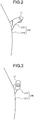
- FIG. 2 is a schematic diagram illustrating a movable part of the vehicle, on which the display control system according to the first embodiment is mounted, when viewed from the rear.
- FIG. 3 is a schematic diagram illustrating a folded state of the movable part of the vehicle, on which the display control system according to the first embodiment is mounted, when viewed from the rear.
- FIG. 1 is a schematic diagram illustrating a vehicle on which a display control system according to a first embodiment is mounted.
- FIG. 2 is a schematic diagram illustrating a movable part of the vehicle, on which the display control system according to the first embodiment is mounted, when viewed from the rear.
- FIG. 3 is a schematic diagram illustrating a folded state of the movable part of the vehicle, on which the display control system according to the first embodiment is mounted, when viewed from the rear.
- the vehicle V includes, as a movable part 200 that is movable with respect to a side part of the vehicle V, a right movable part 210 including the right door (side part door) 211 and a right supporting portion (camera supporting portion) 212 arranged on the right door 211 and a left movable part 220 including a left door (side part door) 221 and a left supporting portion (camera supporting portion) 222 arranged on the left door 221.
- the right movable part 210 and the left movable part 220 are referred to as the movable part 200 when they need not be distinguished from each other.
- the right door 211 is arranged on a right side of the vehicle V in a traveling direction.
- the right door 211 can be opened and closed with respect to the vehicle body of the vehicle V.
- the right door 211 is opened with respect to the vehicle body when a driver is, for example, getting on or off the vehicle.
- the right door 211 may sometimes be opened with respect to the vehicle body in order to check a parking position.
- the right door 211 is closed with respect to the vehicle body when the vehicle V is running.
- the right door 211 is opened and closed such that degree of opening with respect to the vehicle body of the vehicle V is in a range between or equal to, for example, 0° and 60°.
- the right door 211 is stopped in an opened state at a second level or a third level by a cam mechanism of a hinge.
- the degree of opening is 0°.
- the degree of opening is 20°.
- the degree of opening is 60°.
- the right door 211 includes a sensor (not illustrated) that detects open level information on the right door 211.
- the open level information on the right door 211 is an operation amount of the right door 211.
- the open level information on the right door 211 mentioned here is information indicating an open level of the right door 211 and is information on a position in which the right door 211 is stopped in an opened state at the second level or the third level.
- the sensor outputs the open level information on the right door 211 to a detecting unit 43 in a display control device 40 as operation information on the movable part 200.
- the right supporting portion 212 supports a right side camera (side camera) 12.
- the right supporting portion 212 can be opened and closed with respect to the right door 211. As illustrated in FIG. 2 , when the vehicle V is running, the right supporting portion 212 is opened with respect to the right door 211. As illustrated in FIG. 3 and FIG. 4 , the right supporting portion 212 is closed with respect to the right door 211 when the vehicle V is parked.
- the right supporting portion 212 is opened and closed such that degree of opening with respect to the right door 211 is in a range between or equal to, for example, 0° and 80°.
- the degree of opening is 0°.
- the degree of opening is 80°.
- the right supporting portion 212 is movable with respect to the vehicle body of the vehicle V and the right door 211 even when the right door 211 is not operated to be opened or closed.
- the right supporting portion 212 is movable with respect to the vehicle body of the vehicle V in accordance with the right door 211 being opened or closed even when the right supporting portion 212 itself is not operated to be opened or closed.
- the right supporting portion 212 includes a sensor (not illustrated) that detects degree of opening information on the right supporting portion 212.
- the degree of opening information on the right supporting portion 212 indicates an operation amount of the right supporting portion 212.
- the sensor outputs the degree of opening information on the right supporting portion 212 to the detecting unit 43 in the display control device 40 as the operation information on the movable part 200.
- the right door 211 and the right supporting portion 212 configured in this way are movable, as the right movable part 210, with respect to the vehicle body of the vehicle V.
- the state in which the right door 211 is in the fully closed state with respect to the vehicle V and the right supporting portion 212 is in the fully opened state with respect to the right door 211 is referred to as a reference state of the right movable part 210.
- the right movable part 210 is in the reference state when the vehicle V is normally running.
- the left door 221 is arranged on a left side of the vehicle V in the traveling direction.
- the left door 221 can be opened and closed with respect to the vehicle body of the vehicle V.
- the left door 221 is opened with respect to the vehicle body when a vehicle passenger at a passenger seat is getting on or off the vehicle.
- the left door 221 may sometimes be opened with respect to the vehicle body in order to check a parking position.
- the left door 221 is closed with respect to the vehicle body when the vehicle V is running.
- the left door 221 is opened and closed such that degree of opening with respect to the vehicle body of the vehicle V is in a range between or equal to, for example, 0° and 60°.
- the left door 221 is stopped in an opened state at the second level or the third level by the cam mechanism of the hinge.
- the degree of opening is 0°.
- the degree of opening is 20°.
- the degree of opening is 60°.
- the left door 221 includes a sensor (not illustrated) that detects open level information on the left door 221.
- the open level information on the left door 221 is an operation amount of the left door 221.
- the open level information on the left door 221 mentioned here is information indicating an opened level of the left door 221 and is information on a position in which the left door 221 is stopped in an opened state at the second level or the third level.
- the sensor outputs the open level information on the left door 221 to the detecting unit 43 in the display control device 40 as the operation information on the movable part 200.
- the left supporting portion 222 supports a left side camera (side camera) 13.
- the left supporting portion 222 can be opened and closed with respect to the left door 221.
- the left supporting portion 222 is opened with respect to the left door 221 when the vehicle V is running.
- the left supporting portion 222 is closed with respect to the left door 221 when the vehicle V is parked.
- the left supporting portion 222 is opened and closed such that the degree of opening with respect to the left door 221 is in a range between or equal to, for example, 0° and 80°.
- the degree of opening is 0°.
- the degree of opening is 80°.
- the left supporting portion 222 is movable with respect to the vehicle body of the vehicle V and the left door 221 even when the left door 221 is not operated to be opened or closed.
- the left supporting portion 222 is movable with respect to the vehicle body of the vehicle V in accordance with the left door 221 being opened or closed even when the left supporting portion 222 itself is not operated to be opened or closed.
- the left supporting portion 222 includes a sensor (not illustrated) that detects degree of opening information on the left supporting portion 222.
- the degree of opening information on the left supporting portion 222 indicates an operation amount of the left supporting portion 222.
- the sensor outputs the degree of opening information on the left supporting portion 222 to the detecting unit 43 in the display control device 40 as the operation information on the movable part 200.
- the left door 221 and the left supporting portion 222 configured in this way are movable, as the left movable part 220, with respect to the vehicle body of the vehicle V.
- the state in which the left door 221 is in a fully closed state with respect to the vehicle V and the left supporting portion 222 is in a fully opened state with respect to the left door 221 is referred to as a reference state of the left movable part 220.
- the left movable part 220 is in the reference state when the vehicle V is normally running.
- the open/close operation of opening or closing the right supporting portion 212 and the left supporting portion 222 may also be performed by a user, such as a driver, or, alternatively, the right supporting portion 212 and the left supporting portion 222 may also be opened or closed based on an operation state, such as an off state of ignition, of the vehicle V.
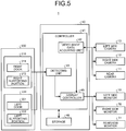
- FIG. 5 is a block diagram illustrating the display control system according to the first embodiment.
- FIG. 6 is a schematic diagram illustrating a configuration example of monitors of the display control system according to the first embodiment.
- the display control system 1 generates a video image that is to be displayed on a right side monitor (display) 32 and a left side monitor (display) 33.
- the display control device 40 and the display control system 1 are mounted on the vehicle V.
- the display control device 40 and the display control system 1 may also be, in addition to the devices mounted on the vehicle V, devices that are portable and can be used in the vehicle V.
- the display control system 1 includes a rear camera 11, the right side camera 12, the left side camera 13, a rearview monitor 31, the right side monitor 32, the left side monitor 33, and the display control device 40.
- the rear camera 11 is arranged at a rear of the vehicle V and captures a video image of an area centering a rear view of the vehicle V.
- the rear camera 11 includes an effective view angle A11 of equal to or greater than, for example, 140°.
- the rear camera 11 outputs rear video image data on the captured video image to a video image data acquiring unit 42 in the display control device 40.
- the right side camera 12 is arranged on the right side of the vehicle V and captures a video image of an area centering the right rear view of the vehicle V.
- the right side camera 12 captures a right rear video image (first video image) displayed on the right side monitor 32.
- the right side camera 12 is arranged in the right movable part 210.
- the right side camera 12 is attached and fixed to the right supporting portion 212.
- the right side camera 12 may also be attached to the right door 211.
- an imaging direction with respect to the vehicle body of the vehicle V is changed in accordance with the operation of the right movable part 210.
- the right side camera 12 outputs the captured right rear video image data to the video image data acquiring unit 42 in the display control device 40.
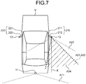
- FIG. 7 is a schematic diagram illustrating the movable parts and the cameras of the vehicle on which the display control system according to the first embodiment is mounted.
- the right side camera 12 captures a range that includes a rearview checking range A21 that corresponds to a range of the right rear view of the vehicle V.
- the rearview checking range A21 captured by the right side camera 12 is substantially the same range as that acquired by a conventional optical right side mirror.
- the right side camera 12 can capture a predetermined imaging range defined by the rearview checking range A21.
- the predetermined imaging range is the same range as the rearview checking range A21 and is referred to as a first imaging range A22.
- the right side camera 12 has an effective view angle A23 including an entire range of the first imaging range A22 when the right movable part 210 is in the reference state.
- the effective view angle A23 of the right side camera 12 is, for example, equal to or greater than 120°.
- the right rear video image data captured by the right side camera 12 is clipped as a first clipping range A24 by a display controller 45 in the display control device 40.
- the left side camera 13 is arranged on the left side of the vehicle V and captures a video image of an area centering the left rear view of the vehicle V.
- the left side camera 13 captures a left rear video image (first video image) displayed on a left side monitor 33.
- the left side camera 13 is arranged in the left movable part 220.
- the left side camera 13 is attached and fixed to the left supporting portion 222.
- the left side camera 13 may also be attached to the left door 221.
- the imaging direction with respect to the vehicle body of the vehicle V is changed in accordance with the operation of the left movable part 220.
- the left side camera 13 outputs the captured left rear video image data to the video image data acquiring unit 42 in the display control device 40.
- a view angle or the like of the left side camera 13 will be described.
- the left side camera 13 captures a rearview checking range that corresponds to a range of the left rear view of the vehicle V.
- the rearview checking range captured by the left side camera 13 is substantially the same range as that acquired by a conventional optical left side mirror.
- the left side camera 13 can capture a predetermined imaging range defined by the rearview checking range.
- the predetermined imaging range is the same range as the rearview checking range and is referred to as the first imaging range.
- the effective view angle of the left side camera 13 is, for example, equal to or greater than 120°.
- the left rear video image captured by the left side camera 13 is clipped as the first clipping range by the display controller 45 in the display control device 40.
- the right side camera 12 and the left side camera 13 are referred to as a side camera when they need not be distinguished from each other.
- the right rear video image and the left rear video image are referred to as a side rear video image when they need not be distinguished from each other.
- the rearview monitor 31 is, as an example, an electronic rearview mirror. When the rearview monitor 31 is used as an electronic rearview mirror, it does not matter whether or not a half mirror is present for checking a rearward with optical reflection.
- the rearview monitor 31 is a display including, for example, a liquid crystal display (LCD) or an organic EL (Organic ElectroLuminescence) display.
- the rearview monitor 31 is arranged at a position that is easily and visually checked by the driver.
- the rearview monitor 31 is arranged in front of the driver of the vehicle V and in an upper part of a center in a vehicle width direction of a windshield S.
- the rearview monitor 31 may also be arranged in the upper part of the center in the vehicle width direction of a dashboard D.
- the rearview monitor 31 displays, based on video image signal output from the display controller 45 in the display control device 40, a rear view video image of the vehicle V.
- a first display image that has been clipped in the same range as a range visually checked by the conventional optical rearview mirror is displayed on the rearview monitor 31.
- the right side monitor 32 is a display including, for example, a liquid crystal display or an organic EL display.
- the right side monitor 32 is arranged at a position that is easily and visually checked by the driver.
- the right side monitor 32 is arranged in front of the driver of the vehicle V and on a right side of the dashboard D in the vehicle width direction.
- the right side monitor 32 displays, based on the video image signal output from the display controller 45 in the display control device 40, a right rear display image of the vehicle V.
- a right side rearview video image (hereinafter, referred to as a "second display image") 100 that images the same range as the rearview checking range A21 is displayed on the right side monitor 32.
- the left side monitor 33 is a display including, for example, a liquid crystal display or an organic EL display.
- the left side monitor 33 is arranged at a position that is easily and visually checked by the driver.
- the left side monitor 33 is arranged in front of the driver of the vehicle V and on a left side of the dashboard D in the vehicle width direction.
- the left side monitor 33 displays, based on the video image signal output from the display controller 45 in the display control device 40, a left rear video image of the vehicle V.
- a left rear display image (hereinafter, referred to as the "second display image") that has been clipped in the same range as the rearview checking range is displayed on the left side monitor 33.
- the right side monitor 32 and the left side monitor 33 are referred to as a side monitor when they need not be distinguished from each other.
- the display control device 40 includes a controller 41 and a storage 49.
- the controller 41 is an arithmetic processing device configured by, for example, a central processing unit (CPU) or the like.
- the controller 41 loads programs stored in the storage 49 into a memory and executes commands included in the programs.
- the controller 41 includes the video image data acquiring unit 42, the detecting unit 43, and the display controller 45.
- the video image data acquiring unit 42 acquires video image data of areas around the vehicle. More specifically, the video image data acquiring unit 42 acquires the rear video image data indicating the rear video image (the second video image) output by the rear camera 11, the right rear video image data (side rear video image data) indicating the right rear video image output by the right side camera 12, and the left rear video image data (side rear video image data) indicating the left rear video image output by the left side camera 13. The video image data acquiring unit 42 outputs the acquired video image data of areas to the display controller 45.
- the detecting unit 43 acquires, from each of the sensors arranged in the movable part 200, as the operation information on the movable part 200, the open level information on the right door 211 and the left door 221 and the degree of opening information on the right supporting portion 212 and the left supporting portion 222.
- the display controller 45 generates a video image and displays the video image on the side monitor. More specifically, the display controller 45 generates a second display image 100 and displays the second display image on the right side monitor 32. The display controller 45 generates the second display image and displays the second display image on the left side monitor 33.
- the display controller 45 When the right movable part 210 is in the reference state, the display controller 45 generates the second display image 100 by clipping the right rear video image acquired by the video image data acquiring unit 42 so as to include the first imaging range A22 and then displays the second display image in the right side monitor 32.
- the display controller 45 When the right movable part 210 is operated and the right side camera 12 faces a direction in which the right side camera 12 is not able to capture the first imaging range A22, the display controller 45 generates the second display image 100 from at least one of the right rear video image and the rear video image acquired by the video image data acquiring unit 42 and then displays the second display image on the right side monitor 32.
- the direction in which the right side camera 12 is not able to capture the first imaging range A22 is a direction in which an optical axis X (see FIG. 10 ) of the right side camera 12 faces the direction in which the first imaging range A22 is not able to be captured.
- the direction in which the first imaging range A22 is not able to be captured may also be a direction in which a part of the first imaging range A22 is not able to be captured. In other words, the case above is a case in which a part of the first imaging range A22 is outside the range of the effective view angle A23 of the right side camera 12.
- the direction of the optical axis X of the right side camera 12 is changed in accordance with the operation amount of the right movable part 210.
- the direction of the optical axis X of the right side camera 12 is represented by an angle ⁇ 1 (hereinafter, referred to as a "first angle") (see FIG. 10 ) of the optical axis X of the right side camera 12 with respect to the right side portion of the vehicle V.
- the first angle ⁇ 1 is 0°.
- a direction in which the right door 211 is opened from the position of the right movable part 210 that is in the reference state is defined as a positive direction
- a direction in which the right supporting portion 212 is closed is defined as a negative direction.
- the first angle ⁇ 1 is calculated based on the open level information on the right door 211 and the degree of opening information on the right supporting portion 212 that are acquired by the detecting unit 43.
- the first angle ⁇ 1 faces the direction in which the first imaging range A22 can be captured.
- the predetermined range is adjusted when the display control device 40 is set up and is previously stored. In the embodiment, if the first angle ⁇ 1 is in the range between or equal to, for example, -10° and 50°, the first angle ⁇ 1 faces the direction in which the first imaging range A22 can be captured. If the first angle ⁇ 1 is in the range, for example, less than -10° or greater than 50°, the first angle ⁇ 1 does not face the direction in which the first imaging range A22 can be captured.
- the display controller 45 Based on whether the first angle ⁇ 1 that indicates the direction of the optical axis X of the right side camera 12 faces the direction in which the first imaging range A22 can be captured, the display controller 45 generates the second display image 100 from at least one of the right rear video image data and the rear video image acquired by the video image data acquiring unit 42 and then displays the second display image on the right side monitor 32.
- the display controller 45 If it is determined that the direction of the optical axis X of the right side camera 12 is the direction in which the first imaging range A22 can be captured, the display controller 45 generates a first clipped video image 101 from the right rear video image by clipping the first clipping range A24 that is the same range as the first imaging range A22. The display controller 45 displays, on the right side monitor 32, the first clipped video image 101 as the second display image 100.
- the display controller 45 If it is determined that the direction of the optical axis X of the right side camera 12 is the direction in which the first imaging range A22 cannot be captured, the display controller 45 generates the second display image 100 from the rear video image in addition to the right rear video image and then displays the second display image on the right side monitor 32.
- the display controller 45 generates the second display image 100 by combining the first clipped video image 101, which is obtained from the right rear video image by clipping the first clipping range A24 that is overlapped with a part of the first imaging range A22, and a second clipped video image 102, which is obtained from the rear video image data by clipping a second clipping range A12 that is overlapped range with a remaining part A25 (see FIG. 11 ) in the first imaging range A22.
- the display controller 45 displays the generated second display image 100 on the right side monitor 32.
- the first clipping range A24 is the maximum range corresponding to the range overlapped with the first imaging range A22. Consequently, the second display image 100 is generated by maximally using the right rear video image of the right side camera 12.
- the display controller 45 may also generate the second display image 100 by combining the first clipped video image 101, which is obtained from the right rear video image by clipping the first clipping range A24 that is overlapped with the area of the right half of the first imaging range A22, and the second clipped video image 102, which is obtained from the rear video image by clipping the second clipping range A12 that is the range overlapped with the remaining part A25 in the first imaging range A22.
- the display controller 45 displays the generated second display image 100 on the right side monitor 32.
- the display controller 45 may also generate the second display image 100 by combining the first clipped video image 101, which is obtained from the right rear video image by clipping the first clipping range A24 that is overlapped with a part of the first imaging range A22, and a monochrome video image 103, which corresponds to the remaining part A25 in the first imaging range A22, and then displays the generated second display image on the right side monitor 32.
- the display controller 45 may also generate, as the second display image 100, the second clipped video image 102, which is obtained from the rear video image by clipping the second clipping range A12 that is the range overlapped with the first imaging range A22, and then displays the generated second display image on the right side monitor 32.
- the display controller 45 In this way, in accordance with an operation status of the right supporting portion 212 and the right door 211 and based on whether the direction of the right side camera 12 faces the direction in which the first imaging range A22 can be captured, the display controller 45 generates the second display image 100 and displays the generated second display image on the right side monitor 32.
- the display controller 45 similarly generates, based on the direction of the left side camera 13, the second display image from at least one of the left rear video image and the rear video image acquired by the video image data acquiring unit 42 and displays the generated second display image on the left side monitor 33.
- the display controller 45 In this way, in accordance with the operation status of the left supporting portion 222 and the left door 221 and based on whether the direction of the left side camera 13 faces the direction in which the first imaging range can be captured, the display controller 45 generates the second display image and displays the generated second display image on the left side monitor 33.
- the storage 49 stores therein data needed for various processes performed in the display control device 40 and stores various processing results.
- the storage 49 is, for example, a semiconductor memory device, such as a random access memory (RAM), a read only memory (ROM), and a flash memory, or a storage device, such as a hard disk and an optical disk.
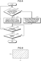
- FIG. 8 is a flowchart illustrating the flow of processes performed in the display control device in the display control system according to the first embodiment.
- the display control system 1 is started up when the vehicle V is moving.
- the video image data acquiring unit 42 in the display control device 40 acquires the rear video image from the rear camera 11, the right rear video image from the right side camera 12, and the left rear video image from the left side camera 13.
- a displaying process performed by the right side monitor 32 will be described.
- the displaying process performed by the left side monitor 33 the same process is also performed.
- the controller 41 determines whether the direction of the camera faces the direction in which the first imaging range A22 can be captured (Step S11). More specifically, the controller 41 calculates the first angle ⁇ 1 based on the open level information on the right door 211 and the degree of opening information on the right supporting portion 212 acquired by the detecting unit 43. Then, the controller 41 determines whether the direction of the right side camera 12 is the direction in which the first imaging range A22 can be captured by determining whether the first angle ⁇ 1 is in the direction in which the first imaging range A22 can be captured.
- Step S11 If the controller 41 determines that the direction of the camera is the direction in which the first imaging range A22 can be captured (Yes at Step S11), the controller 41 proceeds to Step S12. If the controller 41 determines that the direction of the camera is the direction in which the first imaging range A22 cannot be captured (No at Step S11), the controller 41 proceeds to Step S13.
- the controller 41 allows the display controller 45 to clip the first imaging range A22 and display the clipped range on the right side monitor 32 (Step S12). More specifically, the controller 41 allows the display controller 45 to generate, as the second display image 100, the first clipped video image 101 that is obtained from the right rear video image acquired by the video image data acquiring unit 42 by clipping the first clipping range A24 that is the entire range of the first imaging range A22. Then, the controller 41 allows the display controller 45 to display the generated second display image 100 on the right side monitor 32. The controller 41 proceeds to Step S14.
- the controller 41 allows the display controller 45 to generate the second display image 100 by using at least one of the right rear video image and the rear video image, which is obtained from the rear camera 11, acquired by the video image data acquiring unit 42 and then display the generated second display image on the right side monitor 32 (Step S13).
- the controller 41 proceeds to Step S14.
- the controller 41 allows the display controller 45 to generate the second display image 100 by combining the first clipped video image 101, which is obtained from the right rear video image by clipping the first clipping range A24 that is overlapped with a part of the first imaging range A22, and the second clipped video image 102, which is obtained from the rear video image by clipping the second clipping range A12 that is the range overlapped with the remaining part A25 in the first imaging range A22.
- the controller 41 allows the display controller 45 to display the generated second display image 100 on the right side monitor 32.
- the controller 41 may also allow the display controller 45 to generate the second display image 100 by combining the first clipped video image 101, which is obtained from the right rear video image by clipping the first clipping range A24 that is overlapped with the area of the right half of the first imaging range A22, and the second clipped video image 102, which is obtained from the rear video image by clipping the second clipping range A12 that is the range overlapped with remaining part A25 in the first imaging range A22.
- the display controller 45 displays the generated second display image 100 on the right side monitor 32.
- the controller 41 may also allow the display controller 45 to display, on the right side monitor 32, the second display image 100 by combining the first clipped video image 101, which is obtained from the right rear video image by clipping the first clipping range A24 that is overlapped with a part of the first imaging range A22, and the monochrome video image 103 which corresponds to the remaining part A25 in the first imaging range A22.
- the controller 41 may also allow the display controller 45 to generate, as the second display image 100, the second clipped video image 102 that is obtained from the rear video image by clipping the second clipping range A12 that is the range overlapped with the first imaging range A22 and display the generated second display image on the right side monitor 32.
- the controller 41 determines whether the movable part 200 is operated (Step S14). More specifically, if the controller 41 determines, based on the operation information on the movable part 200 acquired by the detecting unit 43, that the movable part 200 is operated (Yes at Step S14), the controller 41 returns to Step S11. If the controller 41 determines, based on the operation information on the movable part 200 acquired by the detecting unit 43, that the movable part 200 is not operated (No at Step S14), the controller 41 proceeds to Step S15.
- the controller 41 determines whether the display is to be ended (Step S15). More specifically, the controller 41 determines whether a condition for ending the display has been satisfied. For example, the condition for ending the display mentioned here is a predetermined elapsed time after an engine or the like of the vehicle V having been stopped. If the controller 41 determines to end the display (Yes at Step S15), the process ends. If the controller 41 determines not to end the display (No at Step S15), the process returns to Step S14.
- the reference state of the right movable part 210 when the right door 211 is closed with respect to the vehicle V will be described with reference to FIG. 7 .
- the optical axis X of the right side camera 12 is in the direction parallel with a longitudinal direction of the vehicle V.
- the effective view angle A23 includes the entire range of the first imaging range A22.
- the controller 41 calculates the first angle ⁇ 1 as 0° based on the operation information acquired by the detecting unit 43. Then, the controller 41 determines that the direction of the right side camera 12 in a case where the first angle ⁇ 1 is 0° is the direction in which the first imaging range A22 can be captured (Yes at Step S11).
- the controller 41 allows the display controller 45 to generate, as the second display image 100, the first clipped video image 101 that is obtained from the right rear video image by clipping the first clipping range A24 that is the entire range of the first imaging range A22. Then, the controller 41 allows the display controller 45 to display the second display image 100 illustrated in FIG. 9 on the right side monitor 32.
- FIG. 9 is a diagram illustrating an example of a video image generated in the display control system according to the first embodiment.
- the second display image 100 illustrated in FIG. 9 is configured by only the first clipped video image 101.
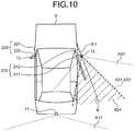
- FIG. 10 is a schematic diagram illustrating the movable parts and the cameras of the vehicle on which the display control system according to the first embodiment is mounted.
- the optical axis X of the right side camera 12 is rotated, counterclockwise, with respect to the optical axis X at the reference state of the right movable part 210 illustrated in FIG. 7 .
- the effective view angle A23 is rotated, counterclockwise, with respect to the first imaging range A22. In the effective view angle A23, a range closer to the vehicle V side than the right door 211 is captured through a side glass G (see FIG. 4 ).
- the effective view angle A23 includes the entire range of the first imaging range A22.
- the controller 41 calculates the first angle ⁇ 1 as 20° based on the operation information acquired by the detecting unit 43. Then, the controller 41 determines that the direction of the right side camera 12 in a case where the first angle ⁇ 1 is 20° is the direction in which the first imaging range A22 can be captured (Yes at Step S11).
- the controller 41 allows the display controller 45 to generate, as the second display image 100, the first clipped video image 101 that is obtained from the right rear video image by clipping the first clipping range A24 that is the entire range of the first imaging range A22 and display the generated second display image on the right side monitor 32.
- the second display image 100 is the same as that illustrated in FIG. 9 .
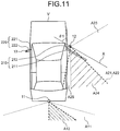
- FIG. 11 is a schematic diagram illustrating the movable parts and the cameras of the vehicle on which the display control system according to the first embodiment is mounted.
- the optical axis X of the right side camera 12 is rotated, counterclockwise, with respect to the optical axis X illustrated in FIG. 10 .
- the effective view angle A23 is rotated, counterclockwise, with respect to the first imaging range A22. In the effective view angle A23, the range closer to the vehicle V than the right door 211 is captured through the side glass G.
- the effective view angle A23 is overlapped with a part of the first imaging range A22.
- the controller 41 calculates the first angle ⁇ 1 as 60° based on the operation information acquired by the detecting unit 43. Then, the controller 41 determines that the direction of the right side camera 12 in a case where the first angle ⁇ 1 is 60° is not the direction in which the first imaging range A22 can be captured (No at Step S11). At Step S13, the controller 41 allows the display controller 45 to generate the second display image 100 from at least one of the right rear video image and the rear video image and display the generated second display image on the right side monitor 32.
- the controller 41 allows the display controller 45 to generate the second display image 100 by combining the first clipped video image 101, which is obtained from the right rear video image by clipping the first clipping range A24 that is overlapped with a part of the first imaging range A22, and the second clipped video image 102, which is obtained from the rear video image by clipping the second clipping range A12 that is the range overlapped with the remaining part A25 in the first imaging range A22.
- the first clipping range A24 is the maximum range corresponding to the range overlapped with the first imaging range A22.
- the controller 41 allows the display controller 45 to display the second display image 100 illustrated in FIG. 12 on the right side monitor 32.
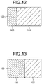
- FIG. 12 is a diagram illustrating another example of the video image generated in the display control system according to the first embodiment.
- the second display image 100 illustrated in FIG. 12 is configured by the first clipped video image 101 and the second clipped video image 102.
- the area of the first clipped video image 101 is greater than the area of the second clipped video image 102.
- the controller 41 may also allow the display controller 45 to generate the second display image 100 by combining the first clipped video image 101, which is obtained from the right rear video image by clipping the first clipping range A24 that is overlapped with the area of the right half of the first imaging range A22, and the second clipped video image 102, which is obtained from the rear video image by clipping the second clipping range A12 that is the range overlapped with the remaining part A25 in the first imaging range A22.
- the controller 41 allows the display controller 45 to display the second display image 100 illustrated in FIG. 13 on the right side monitor 32.
- FIG. 13 is a diagram illustrating another example of the video image generated in the display control system according to the first embodiment.
- the second display image 100 illustrated in FIG. 13 is configured by the first clipped video image 101 and the second clipped video image 102.
- the area of the first clipped video image 101 is the same as the area of the second clipped video image 102.
- the controller 41 may also allow the display controller 45 to generate the second display image 100 by combining the first clipped video image 101, which is obtained from the right rear video image by clipping the first clipping range A24 that is overlapped with a part of the first imaging range A22, and the monochrome video image 103 which corresponds to the remaining part A25 in the first imaging range A22. It is preferable that the first clipping range A24 be the maximum range corresponding to the range overlapped with the first imaging range A22.
- the controller 41 allows the display controller 45 to display the second display image 100 illustrated in FIG. 14 on the right side monitor 32.
- FIG. 14 is a diagram illustrating another example of the video image generated in the display control system according to the first embodiment.
- the second display image 100 illustrated in FIG. 14 is configured by the first clipped video image 101 and the monochrome video image 103.
- the area of the first clipped video image 101 is greater than the area of the monochrome video image 103.
- the controller 41 may also allow the display controller 45 to generate, as the second display image 100, the second clipped video image 102 that is obtained from the rear video image by clipping the second clipping range A12 that is the range overlapped with the first imaging range A22. It is preferable that the second clipping range A12 be the maximum range corresponding to the range overlapped with the first imaging range A22.
- the controller 41 may also allow the display controller 45 to display the second display image 100 illustrated in FIG. 15 on the right side monitor 32.
- FIG. 15 is a diagram illustrating another example of the video image generated in the display control system according to the first embodiment.
- the second display image 100 illustrated in FIG. 15 is configured by only the second clipped video image 102.
- the display control system 1 In this way, in accordance with the operation status of the movable part 200, the display control system 1 generates the second display image 100 and displays the generated second display image on the right side monitor 32.
- the embodiment generates the second display image in accordance with the operation status of the movable part 200 and displays the generated second display image on the side monitor. If the direction of the side camera is the direction in which the first imaging range can be captured, the embodiment generates the second display image, which is obtained from the side rear video image by clipping a clipped view angle that is an entire range of the first imaging range, and displays the generated second display image on the side monitor. If the direction of the side camera is not the direction in which the first imaging range can be captured, the embodiment generates the second display image from at least one of the side rear video image and the rear video image and displays the generated second display image on the side monitor.
- the embodiment can generate an appropriate second display image and display the generated second display image on the side monitor. In this way, the embodiment can generate the appropriate second display image in accordance with the operation status of the movable part 200 and display the generated second display image on the side monitor.
- the embodiment generates and displays the second display image by combining the first clipped video image, which is obtained from the side rear video image by clipping the first clipping range that is overlapped with a part of the first imaging range, and the second clipped video image, which is obtained from the rear video image by clipping the second clipping range that is the range overlapped with the remaining part in the first imaging range. Consequently, regarding the remaining part that is not captured by the side camera and that is included in the first imaging range, it is possible to generate and display the second display image by using the second clipped video image clipped from the rear video image. In this way, it is possible to reduce a lack of the video image in the rearview checking range and allow the area around the vehicle to be appropriately checked.
- the embodiment may also generate and display the second display image by combining the first clipped video image, which is obtained from the side rear video image by clipping the first clipping range that is overlapped with the area of the half of the first imaging range, and the second clipped video image, which is obtained from the rear video image by clipping the second clipping range that is the range overlapped with the remaining part in the first imaging range.
- the embodiment can reduce the lack of the video image in the rearview checking range and allow the area around the vehicle to be appropriately checked.
- the display area of the first clipped video image and the display area of the second clipped video image become the same. Consequently, a driver can easily recognize the first clipped video image and the second clipped video image distinguishably.
- the embodiment may also generate the second display image by combining the first clipped video image, which is obtained from the side rear video image by clipping the first clipping range that is overlapped with a part of the first imaging range, and the monochrome video image which corresponds to the remaining part in the first imaging range. Consequently, it is possible to avoid occurrence of discontinuity of objects to be captured on a joining surface formed by combining the first clipped video image and the second clipped video image. In this way, it is possible to appropriately check the area around the vehicle.
- the embodiment may also generate, as the second display image, the second clipped video image that is obtained from the rear video image by clipping the second clipping range that is the range overlapped with the first imaging range. Consequently, even when the side camera faces the direction in which the first imaging range cannot be captured, it is possible to generate and display the second display image by using the second clipped video image clipped from the rear video image. In this way, it is possible to reduce the lack of the video image in the rearview checking range and allow the area around the vehicle to be appropriately checked.
- FIG. 16 is a schematic diagram illustrating the movable parts and the cameras of the vehicle on which the display control system according to a second embodiment is mounted.
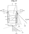
- FIG. 17 is a schematic diagram illustrating the movable parts and the cameras of the vehicle on which the display control system according to the second embodiment is mounted.
- the basic configuration of the display control system 1 is the same as that of the display control system 1 according to the first embodiment. In a description below, components having the same function as those of the display control system 1 are assigned the same or the corresponding reference numerals and descriptions of overlapped portions will be omitted.
- the display control system 1 is different from that according to the first embodiment in that the processes performed in the display controller 45 included in the display control device 40 are different.
- the displaying process performed on the right side monitor 32 in a case where the right movable part 210 is in the reference state is the same as that described in the first embodiment with reference to FIG. 7 .
- FIG. 16 A state in which the right supporting portion 212 is closed at an angle of 10° with respect to the right door 211 will be described with reference to FIG. 16 .
- the optical axis X of the right side camera 12 is rotated clockwise with respect to the optical axis X at the reference state of the right movable part 210 illustrated in FIG. 7 .
- the effective view angle A23 is rotated clockwise with respect to the first imaging range A22.
- the effective view angle A23 includes the entire range of the first imaging range A22.
- the controller 41 calculates the first angle ⁇ 1 as -10° based on the operation information acquired by the detecting unit 43.
- the controller 41 determines that the direction of the right side camera 12 in a case where the first angle ⁇ 1 is -10° is the direction in which the first imaging range A22 can be captured (Yes at Step S11).
- the controller 41 allows the display controller 45 to generate, as the second display image 100, the first clipped video image 101 that is obtained from the right rear video image by clipping the first clipping range A24 that is the entire range of the first imaging range A22.
- the controller 41 allows the display controller 45 to display the second display image 100 on the right side monitor 32.
- the second display image 100 is the same as that illustrated in FIG. 9 .
- FIG. 17 A state in which the right supporting portion 212 is closed at an angle of 40° with respect to the right door 211 will be described with reference to FIG. 17 .
- the optical axis X of the right side camera 12 is rotated clockwise with respect to the optical axis X illustrated in FIG. 16 .
- the effective view angle A23 is rotated clockwise with respect to the first imaging range A22.
- the effective view angle A23 is overlapped with a part of the first imaging range A22.
- the first imaging range A22 includes the remaining part A26 that is not overlapped with the effective view angle A23.
- the controller 41 calculates the first angle ⁇ 1 as -40° based on the operation information acquired by the detecting unit 43.
- the controller 41 determines that the direction of the right side camera 12 in a case where the first angle ⁇ 1 is -40° is the direction in which the first imaging range A22 cannot be captured (No at Step S11).
- the controller 41 allows the display controller 45 to generate the second display image 100 from at least one of the right rear video image and the rear video image and display the generated second display image on the right side monitor 32.
- the controller 41 allows the display controller 45 to generate the second display image 100 by combining the first clipped video image 101, which is obtained from the right rear video image by clipping the first clipping range A24 that is overlapped with a part of the first imaging range A22, and the second clipped video image 102, which is obtained from the rear video image by clipping the second clipping range A12 that is the range overlapped with the remaining part A26 in the first imaging range A22.
- the first clipping range A24 is the maximum range corresponding to the range overlapped with the first imaging range A22.
- the controller 41 allows the display controller 45 to display the second display image 100 illustrated in FIG. 18 on the right side monitor 32.
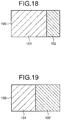
- FIG. 18 is a diagram illustrating an example of a video image generated in the display control system according to the second embodiment.
- the second display image 100 illustrated in FIG. 18 is configured by the first clipped video image 101 and the second clipped video image 102.
- the area of the first clipped video image 101 is greater than the area of the second clipped video image 102.
- the controller 41 may also allow the display controller 45 to generate the second display image 100 by combining the first clipped video image 101, which is obtained from the right rear video image by clipping the first clipping range A24 that is overlapped with the area of the left half of the first imaging range A22, and the second clipped video image 102, which is obtained from the rear video image by clipping the second clipping range A12 that is the range overlapped with the remaining part A26 in the first imaging range A22.
- the controller 41 allows the display controller 45 to display the second display image 100 illustrated in FIG. 19 on the right side monitor 32.
- FIG. 19 is a diagram illustrating another example of the video image generated in the display control system according to the second embodiment.
- the second display image 100 illustrated in FIG. 19 is configured by the first clipped video image 101 and the second clipped video image 102.
- the area of the first clipped video image 101 is the same as the area of the second clipped video image 102.
- the controller 41 may also allow the display controller 45 to generate the second display image 100 by combining the first clipped video image 101, which is obtained from the right rear video image by clipping the first clipping range A24 that is overlapped with a part of the first imaging range A22, and the monochrome video image 103 which corresponds to the remaining part A26 in the first imaging range A22. It is preferable that the first clipping range A24 be the maximum range corresponding to the range overlapped with the first imaging range A22.
- the controller 41 allows the display controller 45 to display the second display image 100 illustrated in FIG. 20 on the right side monitor 32.
- FIG. 20 is a diagram illustrating another example of the video image generated in the display control system according to the second embodiment.
- the second display image 100 illustrated in FIG. 20 is configured by the first clipped video image 101 and the monochrome video image 103.
- the area of the first clipped video image 101 is greater than the area of the monochrome video image 103.
- the controller 41 may also allow the display controller 45 to generate, as the second display image 100, the second clipped video image 102 that is obtained from the rear video image by clipping the second clipping range A12 that is the range overlapped with the first imaging range A22. It is preferable that the second clipping range A12 be the maximum range corresponding to the range overlapped with the first imaging range A22.
- the controller 41 may also allow the display controller 45 to display the second display image 100 illustrated in FIG. 15 on the right side monitor 32.
- FIG. 21 is a schematic diagram illustrating the movable parts and the cameras of the vehicle on which the display control system according to the second embodiment is mounted.
- the optical axis X of the right side camera 12 is rotated clockwise with respect to the optical axis X illustrated in FIG. 17 .
- the optical axis X is extended toward the vehicle interior.
- the effective view angle A23 is not overlapped with the most part of the first imaging range A22.
- the controller 41 calculates the first angle ⁇ 1 as -60° based on the operation information acquired by the detecting unit 43.
- the controller 41 determines that the direction of the right side camera 12 in a case where the first angle ⁇ 1 is -60° is the direction in which the first imaging range A22 cannot be captured (No at Step S11).
- the controller 41 allows the display controller 45 to generate the second display image 100 from the rear video image.
- the controller 41 allows the display controller 45 to display the second display image 100 illustrated in FIG. 15 on the right side monitor 32.
- the display control system 1 generates the second display image 100 in accordance with the operation status of the movable part 200 and displays the generated second display image on the right side monitor 32.
- the embodiment can generate the appropriate second display image and display the generated second display image on the side monitor. In this way, the embodiment can generate the appropriate second display image in accordance with the operation status of the movable part 200 and display the generated second display image on the side monitor.
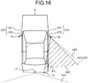
- FIG. 22 is a schematic diagram illustrating the movable parts and the cameras of the vehicle on which the display control system according to the second embodiment is mounted.
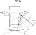
- FIG. 23 is a schematic diagram illustrating the movable parts and the cameras of the vehicle on which the display control system according to the second embodiment is mounted.
- the display control system 1 is different from that described in the first embodiment in that the processes performed by the display controller 45 in the display control device 40 are different.
- FIG. 22 A state in which the right supporting portion 212 is closed at an angle of 40° with respect to the right door 211 while the right door 211 is in the opened state at an angle of 60° with respect to the vehicle V will be described with reference to FIG. 22 .
- the optical axis X of the right side camera 12 is rotated, counterclockwise, with respect to the optical axis X in the reference state in the right movable part 210 illustrated in FIG. 7 .
- the effective view angle A23 the range closer to the vehicle V than the right door 211 is captured through the side glass G.
- the effective view angle A23 is rotated counterclockwise with respect to the first imaging range A22.
- the effective view angle A23 includes the entire range of the first imaging range A22.
- the controller 41 calculates the first angle ⁇ 1 as 20° based on the operation information acquired by the detecting unit 43. Then, the controller 41 determines that the direction of the right side camera 12 in a case where the first angle ⁇ 1 is 20° is the direction in which the first imaging range A22 can be captured (Yes at Step S11).
- the controller 41 allows the display controller 45 to generate, as the second display image 100, the first clipped video image 101 that is obtained from the right rear video image by clipping the first clipping ran0ge A24 that is the entire range of the first imaging range A22. Then, the controller 41 allows the display controller 45 to display the second display image 100 illustrated in FIG. 9 on the right side monitor 32.
- FIG. 23 A state in which the right supporting portion 212 is closed at an angle of 80° with respect to the right door 211 while the right door 211 is in an opened state at an angle of 60° with respect to the vehicle V will be described with reference to FIG. 23 .
- the optical axis X of the right side camera 12 is rotated clockwise with respect to the optical axis X illustrated in FIG. 22 .
- the effective view angle A23 is rotated clockwise with respect to the first imaging range A22. In the effective view angle A23, the range closer to the vehicle V than the right door 211 is captured through the side glass G.
- the effective view angle A23 is overlapped with a part of the first imaging range A22.
- the first imaging range A22 includes the remaining part A26 that is not overlapped with the effective view angle A23.
- the controller 41 calculates the first angle ⁇ 1 as - 20° based on the operation information acquired by the detecting unit 43. Then, the controller 41 determines that the direction of the right side camera 12 in a case where the first angle ⁇ 1 is -20° is the direction in which the first imaging range A22 cannot to be captured (No at Step S11).
- the controller 41 allows the display controller 45 to generate the second display image 100 from at least one of the right rear video image and the rear video image and display the generated second display image on the right side monitor 32.
- a specific display method may be performed by using the same display method used in the second embodiment illustrated in FIG. 17 .
- the controller 41 allows the display controller 45 to display the second display image 100 illustrated in FIG. 18 on the right side monitor 32.
- the controller 41 may also allow the display controller 45 to display the second display image 100 illustrated in FIG. 19 on the right side monitor 32.
- the controller 41 may also allow the display controller 45 to display the second display image 100 illustrated in FIG. 20 on the right side monitor 32.
- the controller 41 may also allow the display controller 45 to display the second display image 100 illustrated in FIG. 15 on the right side monitor 32.
- the embodiment can generate the appropriate second display image and display the generated second display image on the side monitor. In this way, the embodiment can generate the appropriate second display image in accordance with the operation status of the movable part 200 and display the generated video image on the side monitor.
- the display control system 1 has been described. However, the present invention may be carried out in various different modes in addition to the above-described embodiments.
- each of the components included in the display control system 1 illustrated in the drawings are only for conceptually illustrating functions thereof and are not always physically configured as illustrated in the drawings.
- the specific shape of a separate or integrated device is not limited to the drawings.
- all or part of the device can be configured by functionally or physically separating or integrating any of the units depending on various loads or use conditions.
- the configuration of the display control system 1 is implemented by a program that is loaded as software into a memory.
- the configuration has been described as functional blocks implemented by association among the sets of hardware or software.
- the functional blocks may be implemented with only hardware or only software or in various forms using combinations of hardware and software.
- the above-described components include those easily assumable by those skilled in the art and those substantially the same as the above-described components. Furthermore, the above-described components may be combined as appropriate. Furthermore, it is possible to make various types of omission, replacement or change among the components within the scope of the present invention.
- the display control unit 45 When the display control unit 45 generates the second display image by combining the first clipped video image clipped from the side rear video image and the second clipped video image clipped from the rear video image, the display control unit 45 may also draw a line on a boundary or change brightness or luminance so as to distinguish between the first clipped video image and the second clipped video image. Consequently, a driver can easily recognize the first clipped video image and the second clipped video image distinguishably.
- the operation of the right supporting portion 212 or the left supporting portion 222 is not limited to the configuration in which the supporting portion supports the side camera so as to be capable of being folded but may also be opened or closed by sliding in the vehicle width direction or in the vertical direction.
- the direction of the optical axis of the side camera is changed in accordance with an operation amount of the movable part for the sliding from the reference state. If the operation amount of the movable part is within a predetermined range, the side camera faces the direction in which the first imaging range can be captured.
- the predetermined range is adjusted at the time of, for example, setup of the display control device 40 and is previously stored.
- the display controller 45 may also determine whether the direction of the side camera is the direction in which the first imaging range can be captured. For example, if the area of overlapped range is equal to or greater than a predetermined value, the display controller 45 may determine that the direction of the side camera is the direction in which the first imaging range A22 can be captured. For example, if the area of the overlapped range is less than the predetermined value, the display controller 45 may determine that the direction of the side camera is the direction in which the first imaging range A22 cannot be captured.
- the display controller 45 can determine the direction of the side camera based on the area of the overlapped range between the side rear video image and the first imaging range. In this way, even when the display controller 45 cannot acquire the operation amount of the movable part, the display controller 45 can generate the appropriate second display image in accordance with the operation status of the movable part 200 and display the generated second display image on the side monitor.
- the display controller 45 may also perform image processing for detecting the overlapped area between the side rear video image and the rear video image, calculate the direction of the side camera, and determine whether the direction of the side camera is the direction in which the first imaging range A22 can be captured. Consequently, even when the display controller 45 cannot acquire the operation amount of the movable part, the display controller 45 can determine the direction of the side camera based on the image processing for detecting the overlapped area between the side rear video image and the rear video image. In this way, even when the display controller 45 cannot acquire the operation amount of the movable part, the display controller 45 can generate the appropriate second display image in accordance with the operation status of the movable part 200 and display the generated second display image on the side monitor.
- the display controller 45 may also detect, by performing image analysis on the side rear video image, whether reflection is present in the side glass G and does not use the side rear video image if the reflection has been detected. Consequently, it is possible to display the appropriate video image on the side monitor.
- the first imaging range A22 is the same as the rearview checking range A21.
- the first imaging range A22 is not limited to this.
- the first imaging range A22A may also be a range greater than the rearview checking range A21.
- FIG. 24 is a schematic diagram illustrating another example of the movable part of the vehicle on which the display control system is mounted and the camera. With this configuration, it is possible to generate the second display image without distortion due to using an end portion of the video image captured by the side camera and display the generated second display image on the side monitor.
Landscapes
- Engineering & Computer Science (AREA)
- Multimedia (AREA)
- Mechanical Engineering (AREA)
- Signal Processing (AREA)
- Closed-Circuit Television Systems (AREA)
- Fittings On The Vehicle Exterior For Carrying Loads, And Devices For Holding Or Mounting Articles (AREA)
Claims (7)
- Dispositif de commande d'affichage embarqué dans un véhicule (40) comprenant :une unité d'acquisition de données d'image vidéo (42) configurée pour acquérir des données d'image vidéo arrière latérale capturées par une caméra latérale (12, 13) prévue dans une partie mobile (200, 210, 220) qui est configurée pour supporter la caméra latérale (12, 13) de sorte à pouvoir être repliée par rapport à une porte d'un véhicule et configurée pour capturer un vue arrière du véhicule et pour acquérir des données d'image vidéo arrière capturées par une caméra arrière (11) prévue à l'arrière du véhicule et configurée pour capturer la vue arrière du véhicule ; etun contrôleur d'affichage (45) configuré pour afficher, sur un écran latéral (32, 33), les données d'image vidéo arrière latérale et les données d'image vidéo arrière, caractérisé en ce quele contrôleur d'affichage (45) est en outre configuré pour :quand la partie mobile (200, 210, 220) est dans un état de référence dans lequel une direction d'un axe optique (X) de la caméra latérale (12, 13) est une direction dans laquelle une première plage d'imagerie (A22) prédéterminée dans les données d'image vidéo arrière latérale capturées par la caméra latérale (12, 13) peut être entièrement capturée, tronquer la première plage d'imagerie (A22) et afficher les données d'image de vue arrière latérale tronquée sur l'écran latéral (32, 33) ;quand la partie mobile (200, 210, 220) est dans un premier état qui est différent de l'état de référence et dans lequel la direction de l'axe optique (X) de la caméra latérale (12, 13) est une direction dans laquelle la première plage d'imagerie (A22) peut être entièrement capturée, tronquer la première plage d'imagerie (A22) et afficher les données d'image de vue arrière latérale tronquée sur l'écran latéral (32, 33) ; etquand la partie mobile (200, 210, 220) est dans un deuxième état qui est différent de l'état de référence et dans lequel la direction de l'axe optique (X) de la caméra latérale (12, 13) est une direction dans laquelle une partie de la première plage d'imagerie (A22) ne peut pas être capturée, générer des données d'image d'affichage combiné en combinant une première image vidéo tronquée (101) qui est obtenue à partir des données d'image de vue arrière latérale en tronquée une première plage de coupe (A24) qui est recouverte par une partie de la première plage d'imagerie (A22) et une deuxième image vidéo tronquée (102) qui est obtenue à partir des données d'image vidéo en tronquant une deuxième plage de coupe (A12) qui est recouverte par une partie restante (A25) en tant que partie qui ne peut pas être capturée par la caméra latérale (12, 13) dans la première plage d'imagerie (A22), et afficher les données d'image d'affichage combiné sur l'écran latéral (32, 33),dans lequel l'état de référence est un état dans lequel la porte du véhicule est dans un état complètement fermé par rapport au véhicule et la partie mobile est dans un état complètement ouvert par rapport à la porte du véhicule.
- Dispositif de commande d'affichage embarqué dans un véhicule (40) selon la revendication 1, dans lequel, quand la partie mobile (200, 210, 220) est actionnée et que la caméra latérale (12, 13) fait face à la direction dans laquelle la première plage d'imagerie (A22) ne peut pas être totalement capturée, le contrôleur d'affichage (45) est en outre configuré pour afficher, sur l'affichage latéral (32, 33), la première image vidéo tronquée (101) provenant de la caméra latérale (12, 13) et la deuxième image vidéo (102) provenant de la caméra arrière (11) au lieu de la première image vidéo tronquée (101).
- Dispositif de commande d'affichage embarqué dans un véhicule (40) selon la revendication 1 ou 2, comprenant en outre une unité de détection (43) configurée pour acquérir des informations de fonctionnement comportant une quantité de fonctionnement de la partie mobile (200, 210, 220), dans lequel
le contrôleur d'affichage (45) est en outre configuré pour déterminer une direction de face de la caméra latérale (12, 13) sur la base des informations de fonctionnement acquises par l'unité de détection (43). - Dispositif de commande d'affichage embarqué dans un véhicule (40) selon la revendication 3, dans lequel
l'unité de détection (43) est en outre configurée pour détecter la quantité de fonctionnement de la porte latérale (211, 221) ou de la partie portant la caméra (212, 222). - Système de commande d'affichage embarqué dans un véhicule (1) comprenant :le dispositif de commande d'affichage embarqué dans un véhicule (40) selon l'une quelconque des revendications 1 à 4 ; etau moins un élément parmi la partie mobile (200, 210, 220), la caméra latérale (12, 13), la caméra arrière (11), et l'écran latéral (32, 33).
- Procédé de commande d'affichage embarqué dans un véhicule comprenant :une étape d'acquisition de données d'image vidéo d'acquisition de données d'image vidéo arrière latérale capturées par une caméra latérale (12, 13) prévue dans une partie mobile (200, 210, 220) qui est configurée pour supporter la caméra latérale (12, 13) de sorte à pouvoir être repliée par rapport à une porte d'un véhicule et configurée pour capturer une vue arrière du véhicule et pour acquérir des données d'image vidéo arrière capturées par une caméra arrière (11) prévue à l'arrière du véhicule et configurée pour capturer la vue arrière du véhicule ; etune étape de commande d'affichage d'affichage, sur un écran latéral (32, 33), des données d'image vidéo arrière latérale et des données d'image vidéo arrière, caractérisé en ce queil comprend en outre :quand la partie mobile (200, 210, 220) est dans un état de référence dans lequel une direction d'un axe optique (X) de la caméra latérale (12, 13) est une direction dans laquelle une première plage d'imagerie (A22) prédéterminée dans les données d'image vidéo arrière latérale capturées par la caméra latérale (12, 13) peut être entièrement capturée, la coupe des données d'image vidéo arrière latérale de sorte à inclure la première plage d'imagerie (A22) et l'affichage des données d'image de vue arrière latérale tronquée sur l'écran latéral (32, 33) ;quand la partie mobile (200, 210, 220) est dans un premier état qui est différent de l'état de référence et dans lequel la direction de l'axe optique (X) de la caméra latérale (12, 13) est la direction dans laquelle la première plage d'imagerie (A22) prédéterminée dans les données d'image vidéo arrière latérale capturées par la caméra latérale (12, 13) peut être entièrement capturée, la coupe de première plage d'imagerie (A22) et l'affichage des données d'image de vue arrière latérale tronquée sur l'écran latéral (32, 33) ; etquand la partie mobile (200, 210, 220) est dans un deuxième état qui est différent de l'état de référence et dans lequel la direction de l'axe optique (X) de la caméra latérale (12, 13) est une direction dans laquelle une partie de la première plage d'imagerie (A22) ne peut pas être capturée, la génération de données d'image d'affichage combiné en combinant une première image vidéo tronquée (101) qui est obtenue à partir des données d'image vidéo de vue arrière latérale en tronquant une première plage de coupe (A24) qui est recouverte par une partie de la première plage d'imagerie (A22) et une deuxième image vidéo tronquée (102) qui est obtenue à partir des données d'image vidéo en tronquant une deuxième plage de coupe (A12) qui est recouverte par une partie restante (A25) en tant que partie qui ne peut pas être capturée par la caméra latérale (12, 13) dans la première plage d'imagerie (A22), et l'affichage des données d'image d'affichage combiné sur l'écran latéral (32, 33),dans lequel l'état de référence est un état dans lequel la porte du véhicule est dans un état complètement fermé par rapport au véhicule et la partie mobile est dans un état complètement ouvert par rapport à la porte du véhicule.
- Support de stockage non transitoire qui stocke un programme comprenant des instructions pour forcer le dispositif de la revendication 1 pour exécuter les étapes du procédé de la revendication 6.
Applications Claiming Priority (2)
| Application Number | Priority Date | Filing Date | Title |
|---|---|---|---|
| JP2017035372A JP6730612B2 (ja) | 2017-02-27 | 2017-02-27 | 車両用表示制御装置、車両用表示制御システム、車両用表示制御方法およびプログラム |
| PCT/JP2017/040160 WO2018154857A1 (fr) | 2017-02-27 | 2017-11-07 | Dispositif de commande d'affichage de véhicule, système de commande d'affichage de véhicule, procédé de commande d'affichage de véhicule et programme |
Publications (3)
| Publication Number | Publication Date |
|---|---|
| EP3547676A1 EP3547676A1 (fr) | 2019-10-02 |
| EP3547676A4 EP3547676A4 (fr) | 2020-01-08 |
| EP3547676B1 true EP3547676B1 (fr) | 2021-01-06 |
Family
ID=63254310
Family Applications (1)
| Application Number | Title | Priority Date | Filing Date |
|---|---|---|---|
| EP17898227.8A Active EP3547676B1 (fr) | 2017-02-27 | 2017-11-07 | Dispositif de commande d'affichage de véhicule, système de commande d'affichage de véhicule, procédé de commande d'affichage de véhicule et programme |
Country Status (4)
| Country | Link |
|---|---|
| US (1) | US20190308562A1 (fr) |
| EP (1) | EP3547676B1 (fr) |
| JP (1) | JP6730612B2 (fr) |
| WO (1) | WO2018154857A1 (fr) |
Families Citing this family (3)
| Publication number | Priority date | Publication date | Assignee | Title |
|---|---|---|---|---|
| CN109455140B (zh) * | 2017-09-06 | 2022-03-01 | 丰田自动车株式会社 | 图像显示装置 |
| CN111770308B (zh) * | 2020-06-12 | 2022-04-12 | 杭州视在数科信息技术有限公司 | 一种用于重点车辆安全保障的摄像设备追踪方法 |
| DE102021118100A1 (de) | 2021-07-13 | 2023-01-19 | Bayerische Motoren Werke Aktiengesellschaft | Anzeigesystem für ein Fahrzeug |
Family Cites Families (23)
| Publication number | Priority date | Publication date | Assignee | Title |
|---|---|---|---|---|
| US6891563B2 (en) * | 1996-05-22 | 2005-05-10 | Donnelly Corporation | Vehicular vision system |
| JP3607994B2 (ja) * | 2001-11-12 | 2005-01-05 | トヨタ自動車株式会社 | 車両用周辺監視装置 |
| JP2003320898A (ja) * | 2002-04-26 | 2003-11-11 | Sony Corp | 車両用サイドミラー装置 |
| JP4274785B2 (ja) * | 2002-12-12 | 2009-06-10 | パナソニック株式会社 | 運転支援画像生成装置 |
| JP3948431B2 (ja) * | 2003-04-09 | 2007-07-25 | トヨタ自動車株式会社 | 車両用周辺監視装置 |
| JP2005110202A (ja) * | 2003-09-08 | 2005-04-21 | Auto Network Gijutsu Kenkyusho:Kk | カメラ装置及び車両周辺監視装置 |
| JP2006180446A (ja) * | 2004-11-26 | 2006-07-06 | Nissan Motor Co Ltd | 映像撮像装置及び映像撮像方法 |
| JP4924896B2 (ja) * | 2007-07-05 | 2012-04-25 | アイシン精機株式会社 | 車両の周辺監視装置 |
| JP5347257B2 (ja) * | 2007-09-26 | 2013-11-20 | 日産自動車株式会社 | 車両用周辺監視装置および映像表示方法 |
| JP5194679B2 (ja) * | 2007-09-26 | 2013-05-08 | 日産自動車株式会社 | 車両用周辺監視装置および映像表示方法 |
| US8340870B2 (en) * | 2008-09-16 | 2012-12-25 | Honda Motor Co., Ltd. | Vehicle maneuver assistance device |
| JP5112998B2 (ja) * | 2008-09-16 | 2013-01-09 | 本田技研工業株式会社 | 車両周囲監視装置 |
| JP5420216B2 (ja) * | 2008-09-16 | 2014-02-19 | 本田技研工業株式会社 | 車両周囲監視装置 |
| JP5108840B2 (ja) * | 2009-07-29 | 2012-12-26 | クラリオン株式会社 | 車両用周辺監視装置および車両用周辺画像表示方法 |
| JP5500369B2 (ja) * | 2009-08-03 | 2014-05-21 | アイシン精機株式会社 | 車両周辺画像生成装置 |
| JP5503259B2 (ja) * | 2009-11-16 | 2014-05-28 | 富士通テン株式会社 | 車載照明装置、画像処理装置及び画像表示システム |
| JP2011131678A (ja) | 2009-12-24 | 2011-07-07 | Fujitsu Ten Ltd | 画像処理装置、画像処理システム、および、画像処理方法 |
| JP2011135253A (ja) * | 2009-12-24 | 2011-07-07 | Fujitsu Ten Ltd | 画像処理装置、画像処理システム、および、画像処理方法 |
| KR101596751B1 (ko) * | 2014-09-26 | 2016-02-23 | 현대자동차주식회사 | 운전자 맞춤형 사각 영역 표시 방법 및 장치 |
| US9449390B1 (en) * | 2015-05-19 | 2016-09-20 | Ford Global Technologies, Llc | Detecting an extended side view mirror |
| JP6375568B2 (ja) * | 2016-04-28 | 2018-08-22 | 本田技研工業株式会社 | 車両制御システム、車両制御方法、および車両制御プログラム |
| JP6617688B2 (ja) * | 2016-11-29 | 2019-12-11 | トヨタ自動車株式会社 | 車両用ミラーシステム |
| JP6964276B2 (ja) * | 2018-03-07 | 2021-11-10 | パナソニックIpマネジメント株式会社 | 表示制御装置、車両周辺表示システムおよびコンピュータプログラム |
-
2017
- 2017-02-27 JP JP2017035372A patent/JP6730612B2/ja active Active
- 2017-11-07 EP EP17898227.8A patent/EP3547676B1/fr active Active
- 2017-11-07 WO PCT/JP2017/040160 patent/WO2018154857A1/fr unknown
-
2019
- 2019-06-24 US US16/449,626 patent/US20190308562A1/en not_active Abandoned
Non-Patent Citations (1)
| Title |
|---|
| None * |
Also Published As
| Publication number | Publication date |
|---|---|
| WO2018154857A1 (fr) | 2018-08-30 |
| EP3547676A1 (fr) | 2019-10-02 |
| US20190308562A1 (en) | 2019-10-10 |
| JP2018142829A (ja) | 2018-09-13 |
| JP6730612B2 (ja) | 2020-07-29 |
| EP3547676A4 (fr) | 2020-01-08 |
Similar Documents
| Publication | Publication Date | Title |
|---|---|---|
| EP3547676B1 (fr) | Dispositif de commande d'affichage de véhicule, système de commande d'affichage de véhicule, procédé de commande d'affichage de véhicule et programme | |
| US20130096820A1 (en) | Virtual display system for a vehicle | |
| CN109314765B (zh) | 车辆用显示控制装置、显示系统、显示控制方法以及程序 | |
| WO2007043452A1 (fr) | Dispositif imageur embarque sur un vehicule et procede de mesure de distance de prise d’images / de mouvement | |
| KR102091101B1 (ko) | 화상 표시 장치 | |
| EP3487173B1 (fr) | Dispositif de génération d'image, système de génération d'image et procédé de génération d'image et programme | |
| US20110035099A1 (en) | Display control device, display control method and computer program product for the same | |
| US20190221004A1 (en) | Thermal image processing device, infrared imaging apparatus, thermal image processing method, and thermal image processing program | |
| US20190135197A1 (en) | Image generation device, image generation method, recording medium, and image display system | |
| CN104842872A (zh) | 车载拍摄装置 | |
| WO2015182080A1 (fr) | Dispositif d'affichage embarqué dans un véhicule, procédé de commande de dispositif d'affichage embarqué dans un véhicule, et programme | |
| US20170106797A1 (en) | Elctronic mirror device and non-transitory computer-readable recording medium | |
| JP6696558B1 (ja) | 車両用記録制御装置、車両用記録装置、車両用記録制御方法およびプログラム | |
| JP2011150573A (ja) | ドライブレコーダ | |
| US20180077330A1 (en) | Vehicular visual recognition device | |
| JP7259661B2 (ja) | 車両用記録制御装置、車両用記録装置、車両用記録制御方法およびプログラム | |
| CN111693254B (zh) | 车载镜头偏移检测方法与车载镜头偏移检测系统 | |
| US20200384929A1 (en) | On-vehicle display control system and display control method | |
| KR20140054969A (ko) | 차량의 카메라 장치 및 그의 영상 촬영 방법 | |
| US20200265807A1 (en) | Vehicle, display method, and program | |
| US20160332566A1 (en) | Regulation speed display apparatus of vehicle | |
| CN109094557B (zh) | 一种用于显示车辆右盲区图像的控制方法及控制系统 | |
| JP2006107000A (ja) | 画像異常判定方法及び画像異常判定装置 | |
| JPWO2020012992A1 (ja) | 車両用表示装置 | |
| US11643016B2 (en) | Rearview camera field of view with alternative tailgate positions |
Legal Events
| Date | Code | Title | Description |
|---|---|---|---|
| STAA | Information on the status of an ep patent application or granted ep patent |
Free format text: STATUS: THE INTERNATIONAL PUBLICATION HAS BEEN MADE |
|
| PUAI | Public reference made under article 153(3) epc to a published international application that has entered the european phase |
Free format text: ORIGINAL CODE: 0009012 |
|
| STAA | Information on the status of an ep patent application or granted ep patent |
Free format text: STATUS: REQUEST FOR EXAMINATION WAS MADE |
|
| 17P | Request for examination filed |
Effective date: 20190628 |
|
| AK | Designated contracting states |
Kind code of ref document: A1 Designated state(s): AL AT BE BG CH CY CZ DE DK EE ES FI FR GB GR HR HU IE IS IT LI LT LU LV MC MK MT NL NO PL PT RO RS SE SI SK SM TR |
|
| AX | Request for extension of the european patent |
Extension state: BA ME |
|
| A4 | Supplementary search report drawn up and despatched |
Effective date: 20191210 |
|
| RIC1 | Information provided on ipc code assigned before grant |
Ipc: B60R 11/04 20060101ALI20191204BHEP Ipc: H04N 7/18 20060101AFI20191204BHEP Ipc: B60R 1/00 20060101ALI20191204BHEP |
|
| DAV | Request for validation of the european patent (deleted) | ||
| DAX | Request for extension of the european patent (deleted) | ||
| STAA | Information on the status of an ep patent application or granted ep patent |
Free format text: STATUS: EXAMINATION IS IN PROGRESS |
|
| 17Q | First examination report despatched |
Effective date: 20200609 |
|
| GRAP | Despatch of communication of intention to grant a patent |
Free format text: ORIGINAL CODE: EPIDOSNIGR1 |
|
| STAA | Information on the status of an ep patent application or granted ep patent |
Free format text: STATUS: GRANT OF PATENT IS INTENDED |
|
| INTG | Intention to grant announced |
Effective date: 20200909 |
|
| GRAS | Grant fee paid |
Free format text: ORIGINAL CODE: EPIDOSNIGR3 |
|
| GRAA | (expected) grant |
Free format text: ORIGINAL CODE: 0009210 |
|
| STAA | Information on the status of an ep patent application or granted ep patent |
Free format text: STATUS: THE PATENT HAS BEEN GRANTED |
|
| AK | Designated contracting states |
Kind code of ref document: B1 Designated state(s): AL AT BE BG CH CY CZ DE DK EE ES FI FR GB GR HR HU IE IS IT LI LT LU LV MC MK MT NL NO PL PT RO RS SE SI SK SM TR |
|
| REG | Reference to a national code |
Ref country code: GB Ref legal event code: FG4D |
|
| REG | Reference to a national code |
Ref country code: AT Ref legal event code: REF Ref document number: 1353627 Country of ref document: AT Kind code of ref document: T Effective date: 20210115 Ref country code: CH Ref legal event code: EP |
|
| REG | Reference to a national code |
Ref country code: DE Ref legal event code: R096 Ref document number: 602017031233 Country of ref document: DE |
|
| REG | Reference to a national code |
Ref country code: IE Ref legal event code: FG4D |
|
| REG | Reference to a national code |
Ref country code: NL Ref legal event code: MP Effective date: 20210106 |
|
| REG | Reference to a national code |
Ref country code: AT Ref legal event code: MK05 Ref document number: 1353627 Country of ref document: AT Kind code of ref document: T Effective date: 20210106 |
|
| REG | Reference to a national code |
Ref country code: LT Ref legal event code: MG9D |
|
| PG25 | Lapsed in a contracting state [announced via postgrant information from national office to epo] |
Ref country code: LT Free format text: LAPSE BECAUSE OF FAILURE TO SUBMIT A TRANSLATION OF THE DESCRIPTION OR TO PAY THE FEE WITHIN THE PRESCRIBED TIME-LIMIT Effective date: 20210106 Ref country code: BG Free format text: LAPSE BECAUSE OF FAILURE TO SUBMIT A TRANSLATION OF THE DESCRIPTION OR TO PAY THE FEE WITHIN THE PRESCRIBED TIME-LIMIT Effective date: 20210406 Ref country code: NO Free format text: LAPSE BECAUSE OF FAILURE TO SUBMIT A TRANSLATION OF THE DESCRIPTION OR TO PAY THE FEE WITHIN THE PRESCRIBED TIME-LIMIT Effective date: 20210406 Ref country code: PT Free format text: LAPSE BECAUSE OF FAILURE TO SUBMIT A TRANSLATION OF THE DESCRIPTION OR TO PAY THE FEE WITHIN THE PRESCRIBED TIME-LIMIT Effective date: 20210506 Ref country code: GR Free format text: LAPSE BECAUSE OF FAILURE TO SUBMIT A TRANSLATION OF THE DESCRIPTION OR TO PAY THE FEE WITHIN THE PRESCRIBED TIME-LIMIT Effective date: 20210407 Ref country code: HR Free format text: LAPSE BECAUSE OF FAILURE TO SUBMIT A TRANSLATION OF THE DESCRIPTION OR TO PAY THE FEE WITHIN THE PRESCRIBED TIME-LIMIT Effective date: 20210106 Ref country code: FI Free format text: LAPSE BECAUSE OF FAILURE TO SUBMIT A TRANSLATION OF THE DESCRIPTION OR TO PAY THE FEE WITHIN THE PRESCRIBED TIME-LIMIT Effective date: 20210106 |
|
| PG25 | Lapsed in a contracting state [announced via postgrant information from national office to epo] |
Ref country code: AT Free format text: LAPSE BECAUSE OF FAILURE TO SUBMIT A TRANSLATION OF THE DESCRIPTION OR TO PAY THE FEE WITHIN THE PRESCRIBED TIME-LIMIT Effective date: 20210106 Ref country code: PL Free format text: LAPSE BECAUSE OF FAILURE TO SUBMIT A TRANSLATION OF THE DESCRIPTION OR TO PAY THE FEE WITHIN THE PRESCRIBED TIME-LIMIT Effective date: 20210106 Ref country code: RS Free format text: LAPSE BECAUSE OF FAILURE TO SUBMIT A TRANSLATION OF THE DESCRIPTION OR TO PAY THE FEE WITHIN THE PRESCRIBED TIME-LIMIT Effective date: 20210106 Ref country code: LV Free format text: LAPSE BECAUSE OF FAILURE TO SUBMIT A TRANSLATION OF THE DESCRIPTION OR TO PAY THE FEE WITHIN THE PRESCRIBED TIME-LIMIT Effective date: 20210106 Ref country code: SE Free format text: LAPSE BECAUSE OF FAILURE TO SUBMIT A TRANSLATION OF THE DESCRIPTION OR TO PAY THE FEE WITHIN THE PRESCRIBED TIME-LIMIT Effective date: 20210106 |
|
| PG25 | Lapsed in a contracting state [announced via postgrant information from national office to epo] |
Ref country code: IS Free format text: LAPSE BECAUSE OF FAILURE TO SUBMIT A TRANSLATION OF THE DESCRIPTION OR TO PAY THE FEE WITHIN THE PRESCRIBED TIME-LIMIT Effective date: 20210506 |
|
| REG | Reference to a national code |
Ref country code: DE Ref legal event code: R097 Ref document number: 602017031233 Country of ref document: DE |
|
| PG25 | Lapsed in a contracting state [announced via postgrant information from national office to epo] |
Ref country code: CZ Free format text: LAPSE BECAUSE OF FAILURE TO SUBMIT A TRANSLATION OF THE DESCRIPTION OR TO PAY THE FEE WITHIN THE PRESCRIBED TIME-LIMIT Effective date: 20210106 Ref country code: EE Free format text: LAPSE BECAUSE OF FAILURE TO SUBMIT A TRANSLATION OF THE DESCRIPTION OR TO PAY THE FEE WITHIN THE PRESCRIBED TIME-LIMIT Effective date: 20210106 Ref country code: SM Free format text: LAPSE BECAUSE OF FAILURE TO SUBMIT A TRANSLATION OF THE DESCRIPTION OR TO PAY THE FEE WITHIN THE PRESCRIBED TIME-LIMIT Effective date: 20210106 |
|
| PLBE | No opposition filed within time limit |
Free format text: ORIGINAL CODE: 0009261 |
|
| STAA | Information on the status of an ep patent application or granted ep patent |
Free format text: STATUS: NO OPPOSITION FILED WITHIN TIME LIMIT |
|
| PG25 | Lapsed in a contracting state [announced via postgrant information from national office to epo] |
Ref country code: DK Free format text: LAPSE BECAUSE OF FAILURE TO SUBMIT A TRANSLATION OF THE DESCRIPTION OR TO PAY THE FEE WITHIN THE PRESCRIBED TIME-LIMIT Effective date: 20210106 Ref country code: SK Free format text: LAPSE BECAUSE OF FAILURE TO SUBMIT A TRANSLATION OF THE DESCRIPTION OR TO PAY THE FEE WITHIN THE PRESCRIBED TIME-LIMIT Effective date: 20210106 Ref country code: RO Free format text: LAPSE BECAUSE OF FAILURE TO SUBMIT A TRANSLATION OF THE DESCRIPTION OR TO PAY THE FEE WITHIN THE PRESCRIBED TIME-LIMIT Effective date: 20210106 |
|
| 26N | No opposition filed |
Effective date: 20211007 |
|
| PG25 | Lapsed in a contracting state [announced via postgrant information from national office to epo] |
Ref country code: AL Free format text: LAPSE BECAUSE OF FAILURE TO SUBMIT A TRANSLATION OF THE DESCRIPTION OR TO PAY THE FEE WITHIN THE PRESCRIBED TIME-LIMIT Effective date: 20210106 Ref country code: ES Free format text: LAPSE BECAUSE OF FAILURE TO SUBMIT A TRANSLATION OF THE DESCRIPTION OR TO PAY THE FEE WITHIN THE PRESCRIBED TIME-LIMIT Effective date: 20210106 |
|
| PG25 | Lapsed in a contracting state [announced via postgrant information from national office to epo] |
Ref country code: SI Free format text: LAPSE BECAUSE OF FAILURE TO SUBMIT A TRANSLATION OF THE DESCRIPTION OR TO PAY THE FEE WITHIN THE PRESCRIBED TIME-LIMIT Effective date: 20210106 |
|
| PG25 | Lapsed in a contracting state [announced via postgrant information from national office to epo] |
Ref country code: IT Free format text: LAPSE BECAUSE OF FAILURE TO SUBMIT A TRANSLATION OF THE DESCRIPTION OR TO PAY THE FEE WITHIN THE PRESCRIBED TIME-LIMIT Effective date: 20210106 |
|
| PG25 | Lapsed in a contracting state [announced via postgrant information from national office to epo] |
Ref country code: IS Free format text: LAPSE BECAUSE OF FAILURE TO SUBMIT A TRANSLATION OF THE DESCRIPTION OR TO PAY THE FEE WITHIN THE PRESCRIBED TIME-LIMIT Effective date: 20210506 |
|
| PG25 | Lapsed in a contracting state [announced via postgrant information from national office to epo] |
Ref country code: MC Free format text: LAPSE BECAUSE OF FAILURE TO SUBMIT A TRANSLATION OF THE DESCRIPTION OR TO PAY THE FEE WITHIN THE PRESCRIBED TIME-LIMIT Effective date: 20210106 |
|
| REG | Reference to a national code |
Ref country code: CH Ref legal event code: PL |
|
| PG25 | Lapsed in a contracting state [announced via postgrant information from national office to epo] |
Ref country code: LU Free format text: LAPSE BECAUSE OF NON-PAYMENT OF DUE FEES Effective date: 20211107 Ref country code: BE Free format text: LAPSE BECAUSE OF NON-PAYMENT OF DUE FEES Effective date: 20211130 |
|
| REG | Reference to a national code |
Ref country code: BE Ref legal event code: MM Effective date: 20211130 |
|
| PG25 | Lapsed in a contracting state [announced via postgrant information from national office to epo] |
Ref country code: LI Free format text: LAPSE BECAUSE OF NON-PAYMENT OF DUE FEES Effective date: 20211130 Ref country code: CH Free format text: LAPSE BECAUSE OF NON-PAYMENT OF DUE FEES Effective date: 20211130 |
|
| PG25 | Lapsed in a contracting state [announced via postgrant information from national office to epo] |
Ref country code: IE Free format text: LAPSE BECAUSE OF NON-PAYMENT OF DUE FEES Effective date: 20211107 |
|
| PG25 | Lapsed in a contracting state [announced via postgrant information from national office to epo] |
Ref country code: NL Free format text: LAPSE BECAUSE OF NON-PAYMENT OF DUE FEES Effective date: 20210206 Ref country code: CY Free format text: LAPSE BECAUSE OF FAILURE TO SUBMIT A TRANSLATION OF THE DESCRIPTION OR TO PAY THE FEE WITHIN THE PRESCRIBED TIME-LIMIT Effective date: 20210106 |
|
| PG25 | Lapsed in a contracting state [announced via postgrant information from national office to epo] |
Ref country code: HU Free format text: LAPSE BECAUSE OF FAILURE TO SUBMIT A TRANSLATION OF THE DESCRIPTION OR TO PAY THE FEE WITHIN THE PRESCRIBED TIME-LIMIT; INVALID AB INITIO Effective date: 20171107 |
|
| PGFP | Annual fee paid to national office [announced via postgrant information from national office to epo] |
Ref country code: GB Payment date: 20230928 Year of fee payment: 7 |
|
| PGFP | Annual fee paid to national office [announced via postgrant information from national office to epo] |
Ref country code: FR Payment date: 20230929 Year of fee payment: 7 |
|
| PGFP | Annual fee paid to national office [announced via postgrant information from national office to epo] |
Ref country code: DE Payment date: 20230929 Year of fee payment: 7 |
|
| PG25 | Lapsed in a contracting state [announced via postgrant information from national office to epo] |
Ref country code: MK Free format text: LAPSE BECAUSE OF FAILURE TO SUBMIT A TRANSLATION OF THE DESCRIPTION OR TO PAY THE FEE WITHIN THE PRESCRIBED TIME-LIMIT Effective date: 20210106 |