EP3547377B1 - Procédé de fabrication d'un module électroluminescent et module électroluminescent - Google Patents
Procédé de fabrication d'un module électroluminescent et module électroluminescent Download PDFInfo
- Publication number
- EP3547377B1 EP3547377B1 EP19165147.0A EP19165147A EP3547377B1 EP 3547377 B1 EP3547377 B1 EP 3547377B1 EP 19165147 A EP19165147 A EP 19165147A EP 3547377 B1 EP3547377 B1 EP 3547377B1
- Authority
- EP
- European Patent Office
- Prior art keywords
- light
- light emitting
- emitting element
- guiding plate
- encapsulating resin
- Prior art date
- Legal status (The legal status is an assumption and is not a legal conclusion. Google has not performed a legal analysis and makes no representation as to the accuracy of the status listed.)
- Active
Links
- 238000004519 manufacturing process Methods 0.000 title claims description 19
- 229920005989 resin Polymers 0.000 claims description 135
- 239000011347 resin Substances 0.000 claims description 135
- 238000003780 insertion Methods 0.000 claims description 55
- 230000037431 insertion Effects 0.000 claims description 55
- 239000000463 material Substances 0.000 claims description 51
- 239000007767 bonding agent Substances 0.000 claims description 26
- 238000000034 method Methods 0.000 claims description 20
- 238000006243 chemical reaction Methods 0.000 description 43
- 239000010410 layer Substances 0.000 description 35
- 238000009792 diffusion process Methods 0.000 description 24
- 239000004973 liquid crystal related substance Substances 0.000 description 24
- 239000004065 semiconductor Substances 0.000 description 16
- 239000000758 substrate Substances 0.000 description 14
- 239000002184 metal Substances 0.000 description 9
- 229910052751 metal Inorganic materials 0.000 description 9
- 239000011295 pitch Substances 0.000 description 7
- 230000008569 process Effects 0.000 description 7
- 230000003287 optical effect Effects 0.000 description 6
- 230000000052 comparative effect Effects 0.000 description 5
- 230000002093 peripheral effect Effects 0.000 description 5
- 229920000515 polycarbonate Polymers 0.000 description 5
- 239000004417 polycarbonate Substances 0.000 description 5
- 239000000843 powder Substances 0.000 description 5
- GWEVSGVZZGPLCZ-UHFFFAOYSA-N Titan oxide Chemical compound O=[Ti]=O GWEVSGVZZGPLCZ-UHFFFAOYSA-N 0.000 description 4
- 230000007423 decrease Effects 0.000 description 4
- 239000007788 liquid Substances 0.000 description 4
- 229920002050 silicone resin Polymers 0.000 description 4
- 229920005992 thermoplastic resin Polymers 0.000 description 4
- PXHVJJICTQNCMI-UHFFFAOYSA-N Nickel Chemical compound [Ni] PXHVJJICTQNCMI-UHFFFAOYSA-N 0.000 description 3
- 238000005520 cutting process Methods 0.000 description 3
- 238000009826 distribution Methods 0.000 description 3
- 238000005286 illumination Methods 0.000 description 3
- 230000009467 reduction Effects 0.000 description 3
- 229920001187 thermosetting polymer Polymers 0.000 description 3
- KRHYYFGTRYWZRS-UHFFFAOYSA-M Fluoride anion Chemical compound [F-] KRHYYFGTRYWZRS-UHFFFAOYSA-M 0.000 description 2
- VYPSYNLAJGMNEJ-UHFFFAOYSA-N Silicium dioxide Chemical compound O=[Si]=O VYPSYNLAJGMNEJ-UHFFFAOYSA-N 0.000 description 2
- 239000000654 additive Substances 0.000 description 2
- 239000011230 binding agent Substances 0.000 description 2
- 239000010949 copper Substances 0.000 description 2
- 238000010586 diagram Methods 0.000 description 2
- 239000003822 epoxy resin Substances 0.000 description 2
- 239000011521 glass Substances 0.000 description 2
- 239000010931 gold Substances 0.000 description 2
- 238000001746 injection moulding Methods 0.000 description 2
- 150000004767 nitrides Chemical class 0.000 description 2
- 238000005498 polishing Methods 0.000 description 2
- 229920000647 polyepoxide Polymers 0.000 description 2
- 238000012545 processing Methods 0.000 description 2
- 125000006850 spacer group Chemical group 0.000 description 2
- 238000004544 sputter deposition Methods 0.000 description 2
- OGIDPMRJRNCKJF-UHFFFAOYSA-N titanium oxide Inorganic materials [Ti]=O OGIDPMRJRNCKJF-UHFFFAOYSA-N 0.000 description 2
- RYGMFSIKBFXOCR-UHFFFAOYSA-N Copper Chemical compound [Cu] RYGMFSIKBFXOCR-UHFFFAOYSA-N 0.000 description 1
- 239000004593 Epoxy Substances 0.000 description 1
- 240000003380 Passiflora rubra Species 0.000 description 1
- NIXOWILDQLNWCW-UHFFFAOYSA-N acrylic acid group Chemical group C(C=C)(=O)O NIXOWILDQLNWCW-UHFFFAOYSA-N 0.000 description 1
- 230000000996 additive effect Effects 0.000 description 1
- 239000012790 adhesive layer Substances 0.000 description 1
- 230000009286 beneficial effect Effects 0.000 description 1
- 238000005352 clarification Methods 0.000 description 1
- 229910052681 coesite Inorganic materials 0.000 description 1
- 239000003086 colorant Substances 0.000 description 1
- 239000002131 composite material Substances 0.000 description 1
- 239000000470 constituent Substances 0.000 description 1
- 229910052802 copper Inorganic materials 0.000 description 1
- 229910052906 cristobalite Inorganic materials 0.000 description 1
- 239000013078 crystal Substances 0.000 description 1
- 125000004122 cyclic group Chemical group 0.000 description 1
- 230000001419 dependent effect Effects 0.000 description 1
- 238000006073 displacement reaction Methods 0.000 description 1
- 238000001312 dry etching Methods 0.000 description 1
- 230000002349 favourable effect Effects 0.000 description 1
- PCHJSUWPFVWCPO-UHFFFAOYSA-N gold Chemical compound [Au] PCHJSUWPFVWCPO-UHFFFAOYSA-N 0.000 description 1
- 229910052737 gold Inorganic materials 0.000 description 1
- 239000010954 inorganic particle Substances 0.000 description 1
- 238000007689 inspection Methods 0.000 description 1
- 238000000608 laser ablation Methods 0.000 description 1
- 239000011159 matrix material Substances 0.000 description 1
- 239000000203 mixture Substances 0.000 description 1
- 238000012986 modification Methods 0.000 description 1
- 230000004048 modification Effects 0.000 description 1
- 238000000465 moulding Methods 0.000 description 1
- 229910052759 nickel Inorganic materials 0.000 description 1
- 229920000728 polyester Polymers 0.000 description 1
- -1 polyethylene terephthalate Polymers 0.000 description 1
- 229920000139 polyethylene terephthalate Polymers 0.000 description 1
- 239000005020 polyethylene terephthalate Substances 0.000 description 1
- 229920000098 polyolefin Polymers 0.000 description 1
- 229920001296 polysiloxane Polymers 0.000 description 1
- 239000002096 quantum dot Substances 0.000 description 1
- 238000002310 reflectometry Methods 0.000 description 1
- 230000000630 rising effect Effects 0.000 description 1
- 229910052594 sapphire Inorganic materials 0.000 description 1
- 239000010980 sapphire Substances 0.000 description 1
- 239000000377 silicon dioxide Substances 0.000 description 1
- 239000002356 single layer Substances 0.000 description 1
- 238000005476 soldering Methods 0.000 description 1
- 238000003892 spreading Methods 0.000 description 1
- 230000007480 spreading Effects 0.000 description 1
- 229910052682 stishovite Inorganic materials 0.000 description 1
- 239000012815 thermoplastic material Substances 0.000 description 1
- 238000012546 transfer Methods 0.000 description 1
- 238000002834 transmittance Methods 0.000 description 1
- 239000012780 transparent material Substances 0.000 description 1
- 229910052905 tridymite Inorganic materials 0.000 description 1
- 239000011800 void material Substances 0.000 description 1
- 235000012431 wafers Nutrition 0.000 description 1
- 238000001039 wet etching Methods 0.000 description 1
- 239000012463 white pigment Substances 0.000 description 1
Images


Classifications
-
- H—ELECTRICITY
- H01—ELECTRIC ELEMENTS
- H01L—SEMICONDUCTOR DEVICES NOT COVERED BY CLASS H10
- H01L33/00—Semiconductor devices with at least one potential-jump barrier or surface barrier specially adapted for light emission; Processes or apparatus specially adapted for the manufacture or treatment thereof or of parts thereof; Details thereof
- H01L33/48—Semiconductor devices with at least one potential-jump barrier or surface barrier specially adapted for light emission; Processes or apparatus specially adapted for the manufacture or treatment thereof or of parts thereof; Details thereof characterised by the semiconductor body packages
- H01L33/58—Optical field-shaping elements
-
- G—PHYSICS
- G02—OPTICS
- G02F—OPTICAL DEVICES OR ARRANGEMENTS FOR THE CONTROL OF LIGHT BY MODIFICATION OF THE OPTICAL PROPERTIES OF THE MEDIA OF THE ELEMENTS INVOLVED THEREIN; NON-LINEAR OPTICS; FREQUENCY-CHANGING OF LIGHT; OPTICAL LOGIC ELEMENTS; OPTICAL ANALOGUE/DIGITAL CONVERTERS
- G02F1/00—Devices or arrangements for the control of the intensity, colour, phase, polarisation or direction of light arriving from an independent light source, e.g. switching, gating or modulating; Non-linear optics
- G02F1/01—Devices or arrangements for the control of the intensity, colour, phase, polarisation or direction of light arriving from an independent light source, e.g. switching, gating or modulating; Non-linear optics for the control of the intensity, phase, polarisation or colour
- G02F1/13—Devices or arrangements for the control of the intensity, colour, phase, polarisation or direction of light arriving from an independent light source, e.g. switching, gating or modulating; Non-linear optics for the control of the intensity, phase, polarisation or colour based on liquid crystals, e.g. single liquid crystal display cells
- G02F1/133—Constructional arrangements; Operation of liquid crystal cells; Circuit arrangements
- G02F1/1333—Constructional arrangements; Manufacturing methods
- G02F1/1335—Structural association of cells with optical devices, e.g. polarisers or reflectors
- G02F1/1336—Illuminating devices
- G02F1/133602—Direct backlight
- G02F1/133611—Direct backlight including means for improving the brightness uniformity
-
- G—PHYSICS
- G02—OPTICS
- G02F—OPTICAL DEVICES OR ARRANGEMENTS FOR THE CONTROL OF LIGHT BY MODIFICATION OF THE OPTICAL PROPERTIES OF THE MEDIA OF THE ELEMENTS INVOLVED THEREIN; NON-LINEAR OPTICS; FREQUENCY-CHANGING OF LIGHT; OPTICAL LOGIC ELEMENTS; OPTICAL ANALOGUE/DIGITAL CONVERTERS
- G02F1/00—Devices or arrangements for the control of the intensity, colour, phase, polarisation or direction of light arriving from an independent light source, e.g. switching, gating or modulating; Non-linear optics
- G02F1/01—Devices or arrangements for the control of the intensity, colour, phase, polarisation or direction of light arriving from an independent light source, e.g. switching, gating or modulating; Non-linear optics for the control of the intensity, phase, polarisation or colour
- G02F1/13—Devices or arrangements for the control of the intensity, colour, phase, polarisation or direction of light arriving from an independent light source, e.g. switching, gating or modulating; Non-linear optics for the control of the intensity, phase, polarisation or colour based on liquid crystals, e.g. single liquid crystal display cells
- G02F1/133—Constructional arrangements; Operation of liquid crystal cells; Circuit arrangements
- G02F1/1333—Constructional arrangements; Manufacturing methods
- G02F1/1335—Structural association of cells with optical devices, e.g. polarisers or reflectors
- G02F1/1336—Illuminating devices
- G02F1/133602—Direct backlight
- G02F1/133603—Direct backlight with LEDs
-
- H—ELECTRICITY
- H01—ELECTRIC ELEMENTS
- H01L—SEMICONDUCTOR DEVICES NOT COVERED BY CLASS H10
- H01L25/00—Assemblies consisting of a plurality of individual semiconductor or other solid state devices ; Multistep manufacturing processes thereof
- H01L25/03—Assemblies consisting of a plurality of individual semiconductor or other solid state devices ; Multistep manufacturing processes thereof all the devices being of a type provided for in the same subgroup of groups H01L27/00 - H01L33/00, or in a single subclass of H10K, H10N, e.g. assemblies of rectifier diodes
- H01L25/04—Assemblies consisting of a plurality of individual semiconductor or other solid state devices ; Multistep manufacturing processes thereof all the devices being of a type provided for in the same subgroup of groups H01L27/00 - H01L33/00, or in a single subclass of H10K, H10N, e.g. assemblies of rectifier diodes the devices not having separate containers
- H01L25/075—Assemblies consisting of a plurality of individual semiconductor or other solid state devices ; Multistep manufacturing processes thereof all the devices being of a type provided for in the same subgroup of groups H01L27/00 - H01L33/00, or in a single subclass of H10K, H10N, e.g. assemblies of rectifier diodes the devices not having separate containers the devices being of a type provided for in group H01L33/00
- H01L25/0753—Assemblies consisting of a plurality of individual semiconductor or other solid state devices ; Multistep manufacturing processes thereof all the devices being of a type provided for in the same subgroup of groups H01L27/00 - H01L33/00, or in a single subclass of H10K, H10N, e.g. assemblies of rectifier diodes the devices not having separate containers the devices being of a type provided for in group H01L33/00 the devices being arranged next to each other
-
- H—ELECTRICITY
- H01—ELECTRIC ELEMENTS
- H01L—SEMICONDUCTOR DEVICES NOT COVERED BY CLASS H10
- H01L33/00—Semiconductor devices with at least one potential-jump barrier or surface barrier specially adapted for light emission; Processes or apparatus specially adapted for the manufacture or treatment thereof or of parts thereof; Details thereof
- H01L33/36—Semiconductor devices with at least one potential-jump barrier or surface barrier specially adapted for light emission; Processes or apparatus specially adapted for the manufacture or treatment thereof or of parts thereof; Details thereof characterised by the electrodes
-
- H—ELECTRICITY
- H01—ELECTRIC ELEMENTS
- H01L—SEMICONDUCTOR DEVICES NOT COVERED BY CLASS H10
- H01L33/00—Semiconductor devices with at least one potential-jump barrier or surface barrier specially adapted for light emission; Processes or apparatus specially adapted for the manufacture or treatment thereof or of parts thereof; Details thereof
- H01L33/48—Semiconductor devices with at least one potential-jump barrier or surface barrier specially adapted for light emission; Processes or apparatus specially adapted for the manufacture or treatment thereof or of parts thereof; Details thereof characterised by the semiconductor body packages
- H01L33/50—Wavelength conversion elements
- H01L33/507—Wavelength conversion elements the elements being in intimate contact with parts other than the semiconductor body or integrated with parts other than the semiconductor body
-
- H—ELECTRICITY
- H01—ELECTRIC ELEMENTS
- H01L—SEMICONDUCTOR DEVICES NOT COVERED BY CLASS H10
- H01L33/00—Semiconductor devices with at least one potential-jump barrier or surface barrier specially adapted for light emission; Processes or apparatus specially adapted for the manufacture or treatment thereof or of parts thereof; Details thereof
- H01L33/48—Semiconductor devices with at least one potential-jump barrier or surface barrier specially adapted for light emission; Processes or apparatus specially adapted for the manufacture or treatment thereof or of parts thereof; Details thereof characterised by the semiconductor body packages
- H01L33/52—Encapsulations
- H01L33/56—Materials, e.g. epoxy or silicone resin
-
- H—ELECTRICITY
- H01—ELECTRIC ELEMENTS
- H01L—SEMICONDUCTOR DEVICES NOT COVERED BY CLASS H10
- H01L33/00—Semiconductor devices with at least one potential-jump barrier or surface barrier specially adapted for light emission; Processes or apparatus specially adapted for the manufacture or treatment thereof or of parts thereof; Details thereof
- H01L33/48—Semiconductor devices with at least one potential-jump barrier or surface barrier specially adapted for light emission; Processes or apparatus specially adapted for the manufacture or treatment thereof or of parts thereof; Details thereof characterised by the semiconductor body packages
- H01L33/62—Arrangements for conducting electric current to or from the semiconductor body, e.g. lead-frames, wire-bonds or solder balls
-
- G—PHYSICS
- G02—OPTICS
- G02B—OPTICAL ELEMENTS, SYSTEMS OR APPARATUS
- G02B6/00—Light guides; Structural details of arrangements comprising light guides and other optical elements, e.g. couplings
- G02B6/0001—Light guides; Structural details of arrangements comprising light guides and other optical elements, e.g. couplings specially adapted for lighting devices or systems
- G02B6/0011—Light guides; Structural details of arrangements comprising light guides and other optical elements, e.g. couplings specially adapted for lighting devices or systems the light guides being planar or of plate-like form
- G02B6/0013—Means for improving the coupling-in of light from the light source into the light guide
- G02B6/0015—Means for improving the coupling-in of light from the light source into the light guide provided on the surface of the light guide or in the bulk of it
- G02B6/002—Means for improving the coupling-in of light from the light source into the light guide provided on the surface of the light guide or in the bulk of it by shaping at least a portion of the light guide, e.g. with collimating, focussing or diverging surfaces
- G02B6/0021—Means for improving the coupling-in of light from the light source into the light guide provided on the surface of the light guide or in the bulk of it by shaping at least a portion of the light guide, e.g. with collimating, focussing or diverging surfaces for housing at least a part of the light source, e.g. by forming holes or recesses
-
- G—PHYSICS
- G02—OPTICS
- G02B—OPTICAL ELEMENTS, SYSTEMS OR APPARATUS
- G02B6/00—Light guides; Structural details of arrangements comprising light guides and other optical elements, e.g. couplings
- G02B6/0001—Light guides; Structural details of arrangements comprising light guides and other optical elements, e.g. couplings specially adapted for lighting devices or systems
- G02B6/0011—Light guides; Structural details of arrangements comprising light guides and other optical elements, e.g. couplings specially adapted for lighting devices or systems the light guides being planar or of plate-like form
- G02B6/0013—Means for improving the coupling-in of light from the light source into the light guide
- G02B6/0023—Means for improving the coupling-in of light from the light source into the light guide provided by one optical element, or plurality thereof, placed between the light guide and the light source, or around the light source
-
- G—PHYSICS
- G02—OPTICS
- G02F—OPTICAL DEVICES OR ARRANGEMENTS FOR THE CONTROL OF LIGHT BY MODIFICATION OF THE OPTICAL PROPERTIES OF THE MEDIA OF THE ELEMENTS INVOLVED THEREIN; NON-LINEAR OPTICS; FREQUENCY-CHANGING OF LIGHT; OPTICAL LOGIC ELEMENTS; OPTICAL ANALOGUE/DIGITAL CONVERTERS
- G02F1/00—Devices or arrangements for the control of the intensity, colour, phase, polarisation or direction of light arriving from an independent light source, e.g. switching, gating or modulating; Non-linear optics
- G02F1/01—Devices or arrangements for the control of the intensity, colour, phase, polarisation or direction of light arriving from an independent light source, e.g. switching, gating or modulating; Non-linear optics for the control of the intensity, phase, polarisation or colour
- G02F1/13—Devices or arrangements for the control of the intensity, colour, phase, polarisation or direction of light arriving from an independent light source, e.g. switching, gating or modulating; Non-linear optics for the control of the intensity, phase, polarisation or colour based on liquid crystals, e.g. single liquid crystal display cells
- G02F1/133—Constructional arrangements; Operation of liquid crystal cells; Circuit arrangements
- G02F1/1333—Constructional arrangements; Manufacturing methods
- G02F1/1335—Structural association of cells with optical devices, e.g. polarisers or reflectors
- G02F1/1336—Illuminating devices
- G02F1/133601—Illuminating devices for spatial active dimming
-
- G—PHYSICS
- G02—OPTICS
- G02F—OPTICAL DEVICES OR ARRANGEMENTS FOR THE CONTROL OF LIGHT BY MODIFICATION OF THE OPTICAL PROPERTIES OF THE MEDIA OF THE ELEMENTS INVOLVED THEREIN; NON-LINEAR OPTICS; FREQUENCY-CHANGING OF LIGHT; OPTICAL LOGIC ELEMENTS; OPTICAL ANALOGUE/DIGITAL CONVERTERS
- G02F1/00—Devices or arrangements for the control of the intensity, colour, phase, polarisation or direction of light arriving from an independent light source, e.g. switching, gating or modulating; Non-linear optics
- G02F1/01—Devices or arrangements for the control of the intensity, colour, phase, polarisation or direction of light arriving from an independent light source, e.g. switching, gating or modulating; Non-linear optics for the control of the intensity, phase, polarisation or colour
- G02F1/13—Devices or arrangements for the control of the intensity, colour, phase, polarisation or direction of light arriving from an independent light source, e.g. switching, gating or modulating; Non-linear optics for the control of the intensity, phase, polarisation or colour based on liquid crystals, e.g. single liquid crystal display cells
- G02F1/133—Constructional arrangements; Operation of liquid crystal cells; Circuit arrangements
- G02F1/1333—Constructional arrangements; Manufacturing methods
- G02F1/1335—Structural association of cells with optical devices, e.g. polarisers or reflectors
- G02F1/1336—Illuminating devices
- G02F1/133602—Direct backlight
- G02F1/133606—Direct backlight including a specially adapted diffusing, scattering or light controlling members
- G02F1/133607—Direct backlight including a specially adapted diffusing, scattering or light controlling members the light controlling member including light directing or refracting elements, e.g. prisms or lenses
-
- G—PHYSICS
- G02—OPTICS
- G02F—OPTICAL DEVICES OR ARRANGEMENTS FOR THE CONTROL OF LIGHT BY MODIFICATION OF THE OPTICAL PROPERTIES OF THE MEDIA OF THE ELEMENTS INVOLVED THEREIN; NON-LINEAR OPTICS; FREQUENCY-CHANGING OF LIGHT; OPTICAL LOGIC ELEMENTS; OPTICAL ANALOGUE/DIGITAL CONVERTERS
- G02F1/00—Devices or arrangements for the control of the intensity, colour, phase, polarisation or direction of light arriving from an independent light source, e.g. switching, gating or modulating; Non-linear optics
- G02F1/01—Devices or arrangements for the control of the intensity, colour, phase, polarisation or direction of light arriving from an independent light source, e.g. switching, gating or modulating; Non-linear optics for the control of the intensity, phase, polarisation or colour
- G02F1/13—Devices or arrangements for the control of the intensity, colour, phase, polarisation or direction of light arriving from an independent light source, e.g. switching, gating or modulating; Non-linear optics for the control of the intensity, phase, polarisation or colour based on liquid crystals, e.g. single liquid crystal display cells
- G02F1/133—Constructional arrangements; Operation of liquid crystal cells; Circuit arrangements
- G02F1/1333—Constructional arrangements; Manufacturing methods
- G02F1/1335—Structural association of cells with optical devices, e.g. polarisers or reflectors
- G02F1/1336—Illuminating devices
- G02F1/133602—Direct backlight
- G02F1/133612—Electrical details
-
- G—PHYSICS
- G02—OPTICS
- G02F—OPTICAL DEVICES OR ARRANGEMENTS FOR THE CONTROL OF LIGHT BY MODIFICATION OF THE OPTICAL PROPERTIES OF THE MEDIA OF THE ELEMENTS INVOLVED THEREIN; NON-LINEAR OPTICS; FREQUENCY-CHANGING OF LIGHT; OPTICAL LOGIC ELEMENTS; OPTICAL ANALOGUE/DIGITAL CONVERTERS
- G02F1/00—Devices or arrangements for the control of the intensity, colour, phase, polarisation or direction of light arriving from an independent light source, e.g. switching, gating or modulating; Non-linear optics
- G02F1/01—Devices or arrangements for the control of the intensity, colour, phase, polarisation or direction of light arriving from an independent light source, e.g. switching, gating or modulating; Non-linear optics for the control of the intensity, phase, polarisation or colour
- G02F1/13—Devices or arrangements for the control of the intensity, colour, phase, polarisation or direction of light arriving from an independent light source, e.g. switching, gating or modulating; Non-linear optics for the control of the intensity, phase, polarisation or colour based on liquid crystals, e.g. single liquid crystal display cells
- G02F1/133—Constructional arrangements; Operation of liquid crystal cells; Circuit arrangements
- G02F1/1333—Constructional arrangements; Manufacturing methods
- G02F1/1335—Structural association of cells with optical devices, e.g. polarisers or reflectors
- G02F1/1336—Illuminating devices
- G02F1/133614—Illuminating devices using photoluminescence, e.g. phosphors illuminated by UV or blue light
-
- H—ELECTRICITY
- H01—ELECTRIC ELEMENTS
- H01L—SEMICONDUCTOR DEVICES NOT COVERED BY CLASS H10
- H01L2933/00—Details relating to devices covered by the group H01L33/00 but not provided for in its subgroups
- H01L2933/0008—Processes
- H01L2933/0033—Processes relating to semiconductor body packages
- H01L2933/0041—Processes relating to semiconductor body packages relating to wavelength conversion elements
-
- H—ELECTRICITY
- H01—ELECTRIC ELEMENTS
- H01L—SEMICONDUCTOR DEVICES NOT COVERED BY CLASS H10
- H01L2933/00—Details relating to devices covered by the group H01L33/00 but not provided for in its subgroups
- H01L2933/0008—Processes
- H01L2933/0033—Processes relating to semiconductor body packages
- H01L2933/005—Processes relating to semiconductor body packages relating to encapsulations
-
- H—ELECTRICITY
- H01—ELECTRIC ELEMENTS
- H01L—SEMICONDUCTOR DEVICES NOT COVERED BY CLASS H10
- H01L2933/00—Details relating to devices covered by the group H01L33/00 but not provided for in its subgroups
- H01L2933/0008—Processes
- H01L2933/0033—Processes relating to semiconductor body packages
- H01L2933/0058—Processes relating to semiconductor body packages relating to optical field-shaping elements
-
- H—ELECTRICITY
- H01—ELECTRIC ELEMENTS
- H01L—SEMICONDUCTOR DEVICES NOT COVERED BY CLASS H10
- H01L2933/00—Details relating to devices covered by the group H01L33/00 but not provided for in its subgroups
- H01L2933/0008—Processes
- H01L2933/0033—Processes relating to semiconductor body packages
- H01L2933/0066—Processes relating to semiconductor body packages relating to arrangements for conducting electric current to or from the semiconductor body
-
- H—ELECTRICITY
- H01—ELECTRIC ELEMENTS
- H01L—SEMICONDUCTOR DEVICES NOT COVERED BY CLASS H10
- H01L33/00—Semiconductor devices with at least one potential-jump barrier or surface barrier specially adapted for light emission; Processes or apparatus specially adapted for the manufacture or treatment thereof or of parts thereof; Details thereof
- H01L33/02—Semiconductor devices with at least one potential-jump barrier or surface barrier specially adapted for light emission; Processes or apparatus specially adapted for the manufacture or treatment thereof or of parts thereof; Details thereof characterised by the semiconductor bodies
- H01L33/26—Materials of the light emitting region
- H01L33/30—Materials of the light emitting region containing only elements of group III and group V of the periodic system
- H01L33/32—Materials of the light emitting region containing only elements of group III and group V of the periodic system containing nitrogen
Definitions
- US 2014/319560 A1 discloses that semiconductor dies are embedded within polymeric binder to form, e.g., freestanding white light-emitting dies and/or composite wafers containing multiple light-emitting dies embedded in a single volume of binder.
- a light emitting module is defined by claim 7.
- the light-transmissive light guiding plate has a first main surface serving as a light emitting surface from which light exits and a second main surface opposite to the first main surface.
- the second main surface defines a recess on it.
- the light emitting element unit is fixed to the recess of the light guiding plate.
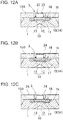
- the light emitting element unit has a light emitting element having a light emission surface and a light adjustment portion containing a fluorescent material, and a bonding wall.
- the light adjustment portion is integrally bonded to the light emitting element.
- the light adjustment portion has an insertion portion disposed in the recess.
- the insertion portion has an outline smaller in size than an inner surface outline of the recess.
- the bonding wall is formed with a light-transmissive bonding agent filled in a ring gap formed between the insertion portion and the recess.
- embodiments described below are intended to give an example of a light emitting module and a method of manufacturing the light emitting module for embodying the technical idea of the present disclosure, and do not limit the present disclosure to the following embodiments.
- the dimensions, materials, shapes, relative arrangements and so on of components described below are not intended to limit the scope of the present disclosure thereto, but are intended to give an example.
- details described in certain embodiment or example is also applicable to other embodiments or examples.
- the sizes, positional relations and so on of members shown in the drawings may be exaggerated for clarification of explanation.
- the light emitting element 11 is bonded to a surface of the light adjustment portion 10 on which a wavelength conversion portion 12 is present.
- the light emitting element 11 has an upper surface as an electrode-formed surface 11d and a lower surface as a light emission surface 11c.
- the light emitting element 11 irradiates the light adjustment portion 10 by emitting light mainly from the light emission surface 11c.
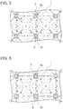
- the light emitting element units 3 are respectively arranged in recesses 1b provided in a matrix form on the light guiding plate 1, and bonded to the light guiding plate 1.
- a direct backlighting liquid crystal display device In a direct backlighting liquid crystal display device, the distance between a liquid crystal panel and a light emitting module is small, and therefore color non-uniformity and luminance non-uniformity of the light emitting module may cause color non-uniformity and luminance non-uniformity of the liquid crystal display device.
- a light emitting module with little color non-uniformity and luminance non-uniformity is desired as a light emitting module for a direct backlighting liquid crystal display device.
- a light-transmissive layer, and a layer having a different refractive index, e.g. a layer of air, between the first main surface 1c of the light guiding plate 1 and the light-transmissive layer may be provided. Accordingly, light is more easily diffused, so that a liquid crystal display device having reduced luminance non-uniformity can be obtained.
- Such a configuration can be obtained by, for example, providing a spacer in at least one appropriately-selected layer between the light guiding plate 1 and light-transmissive layer to separate the light guiding plate 1 and the light-transmissive layer, to thereby provide a layer of air.
- the size of the recess 1b in a plan view may be, for example, in a range of 0.05 mm to 10 mm, preferably 0.1 mm to 2 mm, in terms of a diameter in a circular shape, a long diameter in an elliptical shape, and a length of a diagonal in a quadrangular shape.
- the depth of the recess 1b may be in a range of 0.05 mm to 4 mm, preferably 0.1 mm to 1 mm.
- the distance between the optically functional portion 1a and the recess 1b can be appropriately determined as long as the optically functional portion 1a and the recess 1b are separated from each other.
- the x-direction arrangement pitch p x and the y-direction arrangement pitch p y of recesses 1b in which a plurality of light emitting element units 3 is disposed may be equal between the x-direction and the y-direction as shown in the example in FIG. 2 , or may be different between the x-direction and the y-direction.
- the two directions of arrangement are not necessarily perpendicular to each other.
- x-direction or y-direction arrangement pitches are not necessarily equal, and may be unequal.
- recesses 1b in which light emitting element units 3 are disposed may be arranged such that the distance increases as approaching toward the outer edge from the center of the light guiding plate 1.
- the pitch between light emitting element units 3 disposed in recesses 1b is a distance between the optical axes, in other words, the centers, of light emitting element units 3.
- the light emitting element unit 3 is provided with the light adjustment portion 10 in which the color of light emitted from the light emitting element 11 is adjusted before the light is incident to the light guiding plate 1.
- the light adjustment portion 10 includes the wavelength conversion portion 12 for adjusting the color of light emitted by the light emitting element 11.
- the light adjustment portion 10 is bonded to the light emission surface 11c of the light emitting element 11 to adjust the color of light emitted by the light emitting element 11.
- the light adjustment portion 10 preferably includes the wavelength conversion portion 12 and the light diffusion portion 13. In the light adjustment portion 10, the wavelength conversion portion 12 is bonded to the light diffusion portion 13, and the wavelength conversion portion 12 is disposed on the light emitting element 11 side.
- the wavelength conversion material may be a quantum dot.
- the wavelength conversion material may be disposed in any manner.
- the wavelength conversion material may be substantially evenly distributed, or unevenly distributed.
- a multilayer each containing at least one wavelength conversion member may be provided.
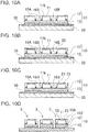
- an electrically conductive film 24 is stacked on the surface of the encapsulating resin 15.
- a metal film 24 of Cu/Ni/Au is formed on substantially the entire surface of each of the electrode terminals 23 of the light emitting element 11 and the encapsulating resin 15 by sputtering.
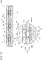
- One light emitting module 100 may be bonded to one wiring substrate.
- a plurality of light emitting modules 100 may be bonded to one wiring substrate. Accordingly, terminal electrodes for electrical connection to the outside (e.g. connectors) can be integrated, in other words, it is not necessary to prepare terminal electrodes for each light emitting module, and therefore the structure of the liquid crystal display device 1000 can be simplified.
Claims (9)
- Procédé de fabrication d'un module électroluminescent (100), le procédé comprenant les opérations suivantes:fourniture d'une plaque de guidage de lumière (1) ayant une première surface principale (1c) servant de surface électroluminescente, et une seconde surface principale (1d) opposée à la première surface principale (1c), la seconde surface principale (1d) définissant une pluralité d'évidements (1b) formés sur celle-ci, et
une pluralité d'unités d'éléments électroluminescents (3), chacune étant liée à la pluralité d'évidements (1b) de la plaque de guidage de lumière (1) pour lier la pluralité d'unités d'éléments électroluminescents (3) à des positions prédéterminées sur la plaque de guidage de lumière (1), et chacune comprenant :un élément électroluminescent (11) ayant une surface électroluminescente (11c) et comprenant une électrode (11b),une partie de réglage de la lumière (10) contenant un matériau fluorescent, l'élément électroluminescent (11) étant intégralement lié à la partie de réglage de la lumière (10), etune première résine d'encapsulation (15A) qui a des surfaces latérales extérieures alignées avec les surfaces latérales extérieures de la partie d'ajustement de la lumière (10), la première résine d'encapsulation (15A) incorporant l'élément électroluminescent (11);fixation des unités d'éléments électroluminescents (3) à la plaque de guidage de la lumière (1) en collant les parties de réglage de la lumière aux évidements (1b), la surface électroluminescente (11c) des éléments électroluminescents (11) affleurant à la seconde surface principale (1d) de la plaque de guidage de la lumière (1),formation d'une paroi de liaison (19) avec un agent de liaison (14) fourni dans un espace annulaire (18) formé entre les surfaces latérales intérieures de l'évidement (1b) et les surfaces latérales extérieures d'une partie d'insertion (17) de l'unité d'élément électroluminescent (3) disposée dans l'évidement (1b), la partie d'insertion (17) ayant un contour plus petit qu'un contour de surface intérieure de l'évidement (1b), une seconde résine d'encapsulation (15B) pour encastrer l'unité d'éléments électroluminescents (3) étant prévue sur la seconde surface principale (1d) de la plaque de guidage de lumière (1), la seconde résine d'encapsulation (15B) étant prévue entre les premières résines d'encapsulation (15A) d'unités d'éléments électroluminescents adjacentes (3); etformation d'un film électriquement conducteur (24) sur les électrodes (11b) des éléments électroluminescents (11) sur la surface de la première résine d'encapsulation (15A) et sur la surface de la seconde résine d'encapsulation (15B). - Procédé selon la revendication 1, dans lequel une capacité volumétrique de l'espace annulaire (18) est supérieure à un volume de la partie d'insertion (17) de l'unité d'éléments électroluminescents (3).
- Procédé selon les revendications 1 ou 2, dans lequel une surface de la paroi de liaison (19) est de niveau avec la seconde surface principale (1d) de la plaque de guidage de lumière (1).
- Procédé selon l'une quelconque des revendications 1 à 3, dans lequel l'agent de liaison (14) est une résine transparente.
- Procédé selon l'une quelconque des revendications 1 à 4, dans lequel l'unité d'éléments électroluminescents (3) est pourvue de la première résine d'encapsulation (15A) qui a des surfaces latérales extérieures affleurant avec les surfaces latérales extérieures de la partie de réglage de la lumière (10), et
l'unité d'élément électroluminescent (3) pourvue de la première résine d'encapsulation (15A) est collée à la plaque de guidage de lumière (1). - Procédé selon la revendication 5, dans lequel la première résine d'encapsulation (15A) comprend une résine blanche.
- Module électroluminescent (100) comprenant:une plaque de guidage de la lumière transparente (1) présentant:une première surface principale (1c) servant de surface électroluminescente d'où sort la lumière etune seconde surface principale (1d) opposée à la première surface principale (1c), la seconde surface principale (1d) définissant une pluralité d'évidements (1b) formés sur celle-ci; etune pluralité d'unités d'éléments électroluminescents (3), chacune étant liée à la pluralité des évidements (1b) de la plaque de guidage de lumière (1).dans lequel chaque unité d'éléments électroluminescents (3) comprend:un élément électroluminescent (11) ayant une surface électroluminescente (11c) et une surface formée par électrodes (11d) opposée à la surface électroluminescente (11c), la surface formée par électrodes (11d) ayant une paire d'électrodes (11b), la surface électroluminescente (11c) des éléments électroluminescents (11) étant de niveau avec la seconde surface principale (1d) de la plaque de guidage de lumière (1), etune partie de réglage de la lumière (10) contenant un matériau fluorescent, la partie de réglage de la lumière (10) étant intégralement liée à l'élément électroluminescent (11) et ayant une partie d'insertion (17) disposée dans l'évidement (1b), la partie d'insertion (17) ayant un contour de taille plus petite qu'un contour de la surface intérieure de l'évidement (1b); etune première résine d'encapsulation (15A) qui a des surfaces latérales extérieures alignées avec les surfaces latérales extérieures de la partie d'ajustement de la lumière (10), la première résine d'encapsulation (15A) incorporant l'élément électroluminescent (11);dans lequel le module électroluminescent (100) comprend en outre:une paroi de liaison (19) formée avec un agent de liaison transparent (14) remplissant un espace annulaire (18) formé entre la partie d'insertion (17) et l'évidement (1b); etune seconde résine d'encapsulation (15B),dans laquelle l'élément électroluminescent (3) est encastré, empilé sur la seconde surface principale (1d) de la plaque de guidage de la lumière (1),la seconde résine d'encapsulation (15B) étant en contact avec une limite entre la seconde surface principale (1d) de la plaque de guidage de lumière (1) et une surface arrière de la paroi de liaison (19),dans lequel le film électriquement conducteur (24) est formé sur l'électrode (11b) de l'élément électroluminescent (11), sur la surface de la première résine d'encapsulation (15A) et sur la surface de la seconde résine d'encapsulation (15B).
- Module électroluminescent (100) selon la revendication 7, dans lequel une capacité volumétrique de l'espace annulaire (18) est supérieure à un volume de la partie d'insertion (17) de l'unité d'élément électroluminescent (3).
- Module électroluminescent (100) selon les revendications 7 ou 8, dans lequel au moins l'une de la première résine d'encapsulation (15A) et de la seconde résine d'encapsulation (15B) contient une résine blanche.
Applications Claiming Priority (2)
| Application Number | Priority Date | Filing Date | Title |
|---|---|---|---|
| JP2018059064 | 2018-03-26 | ||
| JP2019056065A JP6879325B2 (ja) | 2018-03-26 | 2019-03-25 | 発光モジュールの製造方法及び発光モジュール |
Publications (2)
| Publication Number | Publication Date |
|---|---|
| EP3547377A1 EP3547377A1 (fr) | 2019-10-02 |
| EP3547377B1 true EP3547377B1 (fr) | 2021-06-30 |
Family
ID=65991590
Family Applications (1)
| Application Number | Title | Priority Date | Filing Date |
|---|---|---|---|
| EP19165147.0A Active EP3547377B1 (fr) | 2018-03-26 | 2019-03-26 | Procédé de fabrication d'un module électroluminescent et module électroluminescent |
Country Status (2)
| Country | Link |
|---|---|
| US (2) | US11073725B2 (fr) |
| EP (1) | EP3547377B1 (fr) |
Families Citing this family (30)
| Publication number | Priority date | Publication date | Assignee | Title |
|---|---|---|---|---|
| GB2484713A (en) | 2010-10-21 | 2012-04-25 | Optovate Ltd | Illumination apparatus |
| GB201705364D0 (en) | 2017-04-03 | 2017-05-17 | Optovate Ltd | Illumination apparatus |
| GB201705365D0 (en) | 2017-04-03 | 2017-05-17 | Optovate Ltd | Illumination apparatus |
| GB201800574D0 (en) | 2018-01-14 | 2018-02-28 | Optovate Ltd | Illumination apparatus |
| GB201803767D0 (en) | 2018-03-09 | 2018-04-25 | Optovate Ltd | Illumination apparatus |
| CN108287438B (zh) * | 2018-03-30 | 2020-11-27 | 京东方科技集团股份有限公司 | 背光模组和显示设备 |
| GB201807747D0 (en) | 2018-05-13 | 2018-06-27 | Optovate Ltd | Colour micro-LED display apparatus |
| CN108803149B (zh) * | 2018-07-20 | 2021-05-25 | 京东方科技集团股份有限公司 | 面光源及其制作方法以及液晶显示装置 |
| CN110794614B (zh) * | 2018-08-03 | 2022-10-25 | 日亚化学工业株式会社 | 发光模块 |
| DE102018125138A1 (de) * | 2018-10-11 | 2020-04-16 | Osram Opto Semiconductors Gmbh | Strahlungsemittierendes bauteil und verfahren zur herstellung eines strahlungsemittierenden bauteils |
| TW202102883A (zh) | 2019-07-02 | 2021-01-16 | 美商瑞爾D斯帕克有限責任公司 | 定向顯示設備 |
| EP4018236A4 (fr) * | 2019-08-23 | 2023-09-13 | RealD Spark, LLC | Appareil d'éclairage directionnel et affichage de confidentialité |
| JP6864875B2 (ja) | 2019-08-30 | 2021-04-28 | 日亜化学工業株式会社 | 発光モジュール及びその製造方法 |
| WO2021050918A1 (fr) | 2019-09-11 | 2021-03-18 | Reald Spark, Llc | Appareil d'éclairage apte à être commuté et affichage de confidentialité |
| WO2021067612A1 (fr) | 2019-10-03 | 2021-04-08 | Reald Spark, Llc | Appareil d'éclairage comprenant des nanostructures optiques passives |
| CN114730851A (zh) | 2019-10-03 | 2022-07-08 | 瑞尔D斯帕克有限责任公司 | 包括无源光学纳米结构的照明设备 |
| JP6828794B1 (ja) * | 2019-11-29 | 2021-02-10 | 日亜化学工業株式会社 | 面発光光源 |
| US11581460B2 (en) | 2019-12-25 | 2023-02-14 | Nichia Corporation | Light emitting module and method for manufacturing light emitting module |
| JP7097918B2 (ja) * | 2020-01-21 | 2022-07-08 | Nissha株式会社 | シート状デバイス及びその製造方法 |
| WO2021153561A1 (fr) | 2020-01-31 | 2021-08-05 | 日亜化学工業株式会社 | Source de lumière plane |
| TWI823371B (zh) | 2020-01-31 | 2023-11-21 | 日商日亞化學工業股份有限公司 | 面狀光源 |
| JP7066964B2 (ja) * | 2020-01-31 | 2022-05-16 | 日亜化学工業株式会社 | 面状光源 |
| WO2021168090A1 (fr) | 2020-02-20 | 2021-08-26 | Reald Spark, Llc | Appareil d'éclairage et d'affichage |
| TWI786715B (zh) | 2020-07-21 | 2022-12-11 | 日商日亞化學工業股份有限公司 | 發光模組及面狀光源 |
| JP7144694B2 (ja) | 2020-07-31 | 2022-09-30 | 日亜化学工業株式会社 | 発光モジュール、面状光源、液晶表示装置 |
| TWI807401B (zh) * | 2020-08-31 | 2023-07-01 | 日商日亞化學工業股份有限公司 | 發光模組之製造方法 |
| WO2022071110A1 (fr) * | 2020-09-29 | 2022-04-07 | 日亜化学工業株式会社 | Module électroluminescent et source de lumière plane |
| JP7277865B2 (ja) * | 2020-10-29 | 2023-05-19 | 日亜化学工業株式会社 | 面状光源及びその製造方法 |
| JP7368750B2 (ja) * | 2021-07-29 | 2023-10-25 | 日亜化学工業株式会社 | 発光モジュールおよび面状光源 |
| CN114265141B (zh) * | 2021-12-23 | 2023-10-03 | 武汉华星光电技术有限公司 | 导光板、背光模组以及显示装置 |
Family Cites Families (22)
| Publication number | Priority date | Publication date | Assignee | Title |
|---|---|---|---|---|
| US20020063520A1 (en) * | 2000-11-29 | 2002-05-30 | Huei-Che Yu | Pre-formed fluorescent plate - LED device |
| JP2007018936A (ja) | 2005-07-08 | 2007-01-25 | Toyoda Gosei Co Ltd | 光源装置 |
| JP5052860B2 (ja) | 2005-12-15 | 2012-10-17 | 三菱電機株式会社 | 面状光源装置及びこれを用いた表示装置 |
| JP2007227286A (ja) | 2006-02-27 | 2007-09-06 | Seiko Instruments Inc | 照明装置、及びこれを用いた表示装置 |
| US7727806B2 (en) * | 2006-05-01 | 2010-06-01 | Charles Stark Draper Laboratory, Inc. | Systems and methods for high density multi-component modules |
| JP5145552B2 (ja) | 2007-02-22 | 2013-02-20 | 国立大学法人豊橋技術科学大学 | 超伝導磁気センサ用冷却装置 |
| JP2010008837A (ja) | 2008-06-30 | 2010-01-14 | Hitachi Displays Ltd | 液晶表示装置 |
| US8545083B2 (en) | 2009-12-22 | 2013-10-01 | Sumita Optical Glass, Inc. | Light-emitting device, light source and method of manufacturing the same |
| JP2011210674A (ja) | 2010-03-30 | 2011-10-20 | Sumita Optical Glass Inc | 発光装置 |
| DE102010028246A1 (de) | 2010-04-27 | 2011-10-27 | Osram Opto Semiconductors Gmbh | Optoelektronisches Bauelement und Verfahren zum Herstellen eines optoelektronischen Bauelements |
| US20140028953A1 (en) * | 2011-01-26 | 2014-01-30 | Hidenao Kubota | Liquid crystal display device |
| US20120327649A1 (en) | 2011-06-24 | 2012-12-27 | Xicato, Inc. | Led based illumination module with a lens element |
| US8704262B2 (en) * | 2011-08-11 | 2014-04-22 | Goldeneye, Inc. | Solid state light sources with common luminescent and heat dissipating surfaces |
| US8907362B2 (en) | 2012-01-24 | 2014-12-09 | Cooledge Lighting Inc. | Light-emitting dies incorporating wavelength-conversion materials and related methods |
| JP2016533030A (ja) | 2013-07-24 | 2016-10-20 | クーレッジ ライティング インコーポレイテッド | 波長変換材料を組み込む発光ダイおよび関連方法 |
| JP6119490B2 (ja) | 2013-07-31 | 2017-04-26 | ソニー株式会社 | 光源装置、および表示装置 |
| JP6552190B2 (ja) | 2014-12-11 | 2019-07-31 | シチズン電子株式会社 | 発光装置及び発光装置の製造方法 |
| KR101636516B1 (ko) | 2015-03-10 | 2016-07-06 | 한국광기술원 | 렌즈 일체형 발광다이오드 모듈의 제조방법 |
| WO2016171109A1 (fr) | 2015-04-20 | 2016-10-27 | シャープ株式会社 | Dispositif d'éclairage, dispositif d'affichage et dispositif de réception de télévision |
| JP6249002B2 (ja) | 2015-09-30 | 2017-12-20 | 日亜化学工業株式会社 | 発光装置の製造方法 |
| DE102015121074A1 (de) * | 2015-12-03 | 2017-06-08 | Osram Opto Semiconductors Gmbh | Halbleiterbauteil mit lichtleiterschicht |
| EP3639297A4 (fr) * | 2017-06-12 | 2021-01-20 | Uniqarta, Inc. | Assemblage parallèle de composants discrets sur un substrat |
-
2019
- 2019-03-26 US US16/365,012 patent/US11073725B2/en active Active
- 2019-03-26 EP EP19165147.0A patent/EP3547377B1/fr active Active
-
2021
- 2021-06-22 US US17/304,548 patent/US11886078B2/en active Active
Non-Patent Citations (1)
| Title |
|---|
| None * |
Also Published As
| Publication number | Publication date |
|---|---|
| EP3547377A1 (fr) | 2019-10-02 |
| US20190294004A1 (en) | 2019-09-26 |
| US11073725B2 (en) | 2021-07-27 |
| US20210341794A1 (en) | 2021-11-04 |
| US11886078B2 (en) | 2024-01-30 |
Similar Documents
| Publication | Publication Date | Title |
|---|---|---|
| EP3547377B1 (fr) | Procédé de fabrication d'un module électroluminescent et module électroluminescent | |
| EP3547378B1 (fr) | Module électroluminescent | |
| US11221519B2 (en) | Light emitting module | |
| KR102512369B1 (ko) | 발광 모듈의 제조 방법 및 발광 모듈 | |
| US11616169B2 (en) | Light emitting module with concave surface light guide plate | |
| US11899306B2 (en) | Light emitting device | |
| US10930624B2 (en) | Light-emitting module | |
| JP2020107584A (ja) | 発光モジュール | |
| JP7108203B2 (ja) | 発光モジュールの製造方法 | |
| JP7007591B2 (ja) | 発光モジュール | |
| US11342314B2 (en) | Light-emitting module |
Legal Events
| Date | Code | Title | Description |
|---|---|---|---|
| PUAI | Public reference made under article 153(3) epc to a published international application that has entered the european phase |
Free format text: ORIGINAL CODE: 0009012 |
|
| STAA | Information on the status of an ep patent application or granted ep patent |
Free format text: STATUS: THE APPLICATION HAS BEEN PUBLISHED |
|
| AK | Designated contracting states |
Kind code of ref document: A1 Designated state(s): AL AT BE BG CH CY CZ DE DK EE ES FI FR GB GR HR HU IE IS IT LI LT LU LV MC MK MT NL NO PL PT RO RS SE SI SK SM TR |
|
| AX | Request for extension of the european patent |
Extension state: BA ME |
|
| STAA | Information on the status of an ep patent application or granted ep patent |
Free format text: STATUS: REQUEST FOR EXAMINATION WAS MADE |
|
| 17P | Request for examination filed |
Effective date: 20200331 |
|
| RBV | Designated contracting states (corrected) |
Designated state(s): AL AT BE BG CH CY CZ DE DK EE ES FI FR GB GR HR HU IE IS IT LI LT LU LV MC MK MT NL NO PL PT RO RS SE SI SK SM TR |
|
| STAA | Information on the status of an ep patent application or granted ep patent |
Free format text: STATUS: EXAMINATION IS IN PROGRESS |
|
| 17Q | First examination report despatched |
Effective date: 20200803 |
|
| STAA | Information on the status of an ep patent application or granted ep patent |
Free format text: STATUS: EXAMINATION IS IN PROGRESS |
|
| GRAP | Despatch of communication of intention to grant a patent |
Free format text: ORIGINAL CODE: EPIDOSNIGR1 |
|
| STAA | Information on the status of an ep patent application or granted ep patent |
Free format text: STATUS: GRANT OF PATENT IS INTENDED |
|
| RIC1 | Information provided on ipc code assigned before grant |
Ipc: H01L 33/58 20100101ALI20210217BHEP Ipc: H01L 33/50 20100101AFI20210217BHEP Ipc: F21V 8/00 20060101ALN20210217BHEP Ipc: G02F 1/1335 20060101ALN20210217BHEP Ipc: H01L 25/075 20060101ALN20210217BHEP |
|
| RIC1 | Information provided on ipc code assigned before grant |
Ipc: H01L 25/075 20060101ALN20210222BHEP Ipc: F21V 8/00 20060101ALN20210222BHEP Ipc: G02F 1/1335 20060101ALN20210222BHEP Ipc: H01L 33/50 20100101AFI20210222BHEP Ipc: H01L 33/58 20100101ALI20210222BHEP |
|
| INTG | Intention to grant announced |
Effective date: 20210310 |
|
| GRAS | Grant fee paid |
Free format text: ORIGINAL CODE: EPIDOSNIGR3 |
|
| GRAA | (expected) grant |
Free format text: ORIGINAL CODE: 0009210 |
|
| STAA | Information on the status of an ep patent application or granted ep patent |
Free format text: STATUS: THE PATENT HAS BEEN GRANTED |
|
| AK | Designated contracting states |
Kind code of ref document: B1 Designated state(s): AL AT BE BG CH CY CZ DE DK EE ES FI FR GB GR HR HU IE IS IT LI LT LU LV MC MK MT NL NO PL PT RO RS SE SI SK SM TR |
|
| REG | Reference to a national code |
Ref country code: CH Ref legal event code: EP |
|
| REG | Reference to a national code |
Ref country code: AT Ref legal event code: REF Ref document number: 1407167 Country of ref document: AT Kind code of ref document: T Effective date: 20210715 |
|
| REG | Reference to a national code |
Ref country code: DE Ref legal event code: R096 Ref document number: 602019005641 Country of ref document: DE |
|
| REG | Reference to a national code |
Ref country code: IE Ref legal event code: FG4D |
|
| REG | Reference to a national code |
Ref country code: LT Ref legal event code: MG9D |
|
| PG25 | Lapsed in a contracting state [announced via postgrant information from national office to epo] |
Ref country code: BG Free format text: LAPSE BECAUSE OF FAILURE TO SUBMIT A TRANSLATION OF THE DESCRIPTION OR TO PAY THE FEE WITHIN THE PRESCRIBED TIME-LIMIT Effective date: 20210930 Ref country code: HR Free format text: LAPSE BECAUSE OF FAILURE TO SUBMIT A TRANSLATION OF THE DESCRIPTION OR TO PAY THE FEE WITHIN THE PRESCRIBED TIME-LIMIT Effective date: 20210630 Ref country code: FI Free format text: LAPSE BECAUSE OF FAILURE TO SUBMIT A TRANSLATION OF THE DESCRIPTION OR TO PAY THE FEE WITHIN THE PRESCRIBED TIME-LIMIT Effective date: 20210630 |
|
| REG | Reference to a national code |
Ref country code: NL Ref legal event code: MP Effective date: 20210630 |
|
| REG | Reference to a national code |
Ref country code: AT Ref legal event code: MK05 Ref document number: 1407167 Country of ref document: AT Kind code of ref document: T Effective date: 20210630 |
|
| PG25 | Lapsed in a contracting state [announced via postgrant information from national office to epo] |
Ref country code: SE Free format text: LAPSE BECAUSE OF FAILURE TO SUBMIT A TRANSLATION OF THE DESCRIPTION OR TO PAY THE FEE WITHIN THE PRESCRIBED TIME-LIMIT Effective date: 20210630 Ref country code: RS Free format text: LAPSE BECAUSE OF FAILURE TO SUBMIT A TRANSLATION OF THE DESCRIPTION OR TO PAY THE FEE WITHIN THE PRESCRIBED TIME-LIMIT Effective date: 20210630 Ref country code: LV Free format text: LAPSE BECAUSE OF FAILURE TO SUBMIT A TRANSLATION OF THE DESCRIPTION OR TO PAY THE FEE WITHIN THE PRESCRIBED TIME-LIMIT Effective date: 20210630 Ref country code: NO Free format text: LAPSE BECAUSE OF FAILURE TO SUBMIT A TRANSLATION OF THE DESCRIPTION OR TO PAY THE FEE WITHIN THE PRESCRIBED TIME-LIMIT Effective date: 20210930 Ref country code: GR Free format text: LAPSE BECAUSE OF FAILURE TO SUBMIT A TRANSLATION OF THE DESCRIPTION OR TO PAY THE FEE WITHIN THE PRESCRIBED TIME-LIMIT Effective date: 20211001 |
|
| PG25 | Lapsed in a contracting state [announced via postgrant information from national office to epo] |
Ref country code: SK Free format text: LAPSE BECAUSE OF FAILURE TO SUBMIT A TRANSLATION OF THE DESCRIPTION OR TO PAY THE FEE WITHIN THE PRESCRIBED TIME-LIMIT Effective date: 20210630 Ref country code: EE Free format text: LAPSE BECAUSE OF FAILURE TO SUBMIT A TRANSLATION OF THE DESCRIPTION OR TO PAY THE FEE WITHIN THE PRESCRIBED TIME-LIMIT Effective date: 20210630 Ref country code: ES Free format text: LAPSE BECAUSE OF FAILURE TO SUBMIT A TRANSLATION OF THE DESCRIPTION OR TO PAY THE FEE WITHIN THE PRESCRIBED TIME-LIMIT Effective date: 20210630 Ref country code: RO Free format text: LAPSE BECAUSE OF FAILURE TO SUBMIT A TRANSLATION OF THE DESCRIPTION OR TO PAY THE FEE WITHIN THE PRESCRIBED TIME-LIMIT Effective date: 20210630 Ref country code: PT Free format text: LAPSE BECAUSE OF FAILURE TO SUBMIT A TRANSLATION OF THE DESCRIPTION OR TO PAY THE FEE WITHIN THE PRESCRIBED TIME-LIMIT Effective date: 20211102 Ref country code: NL Free format text: LAPSE BECAUSE OF FAILURE TO SUBMIT A TRANSLATION OF THE DESCRIPTION OR TO PAY THE FEE WITHIN THE PRESCRIBED TIME-LIMIT Effective date: 20210630 Ref country code: SM Free format text: LAPSE BECAUSE OF FAILURE TO SUBMIT A TRANSLATION OF THE DESCRIPTION OR TO PAY THE FEE WITHIN THE PRESCRIBED TIME-LIMIT Effective date: 20210630 Ref country code: AT Free format text: LAPSE BECAUSE OF FAILURE TO SUBMIT A TRANSLATION OF THE DESCRIPTION OR TO PAY THE FEE WITHIN THE PRESCRIBED TIME-LIMIT Effective date: 20210630 Ref country code: CZ Free format text: LAPSE BECAUSE OF FAILURE TO SUBMIT A TRANSLATION OF THE DESCRIPTION OR TO PAY THE FEE WITHIN THE PRESCRIBED TIME-LIMIT Effective date: 20210630 |
|
| PG25 | Lapsed in a contracting state [announced via postgrant information from national office to epo] |
Ref country code: PL Free format text: LAPSE BECAUSE OF FAILURE TO SUBMIT A TRANSLATION OF THE DESCRIPTION OR TO PAY THE FEE WITHIN THE PRESCRIBED TIME-LIMIT Effective date: 20210630 |
|
| REG | Reference to a national code |
Ref country code: DE Ref legal event code: R097 Ref document number: 602019005641 Country of ref document: DE |
|
| PG25 | Lapsed in a contracting state [announced via postgrant information from national office to epo] |
Ref country code: DK Free format text: LAPSE BECAUSE OF FAILURE TO SUBMIT A TRANSLATION OF THE DESCRIPTION OR TO PAY THE FEE WITHIN THE PRESCRIBED TIME-LIMIT Effective date: 20210630 |
|
| PLBE | No opposition filed within time limit |
Free format text: ORIGINAL CODE: 0009261 |
|
| STAA | Information on the status of an ep patent application or granted ep patent |
Free format text: STATUS: NO OPPOSITION FILED WITHIN TIME LIMIT |
|
| PG25 | Lapsed in a contracting state [announced via postgrant information from national office to epo] |
Ref country code: AL Free format text: LAPSE BECAUSE OF FAILURE TO SUBMIT A TRANSLATION OF THE DESCRIPTION OR TO PAY THE FEE WITHIN THE PRESCRIBED TIME-LIMIT Effective date: 20210630 |
|
| 26N | No opposition filed |
Effective date: 20220331 |
|
| PG25 | Lapsed in a contracting state [announced via postgrant information from national office to epo] |
Ref country code: IT Free format text: LAPSE BECAUSE OF FAILURE TO SUBMIT A TRANSLATION OF THE DESCRIPTION OR TO PAY THE FEE WITHIN THE PRESCRIBED TIME-LIMIT Effective date: 20210630 |
|
| PG25 | Lapsed in a contracting state [announced via postgrant information from national office to epo] |
Ref country code: MC Free format text: LAPSE BECAUSE OF FAILURE TO SUBMIT A TRANSLATION OF THE DESCRIPTION OR TO PAY THE FEE WITHIN THE PRESCRIBED TIME-LIMIT Effective date: 20210630 |
|
| REG | Reference to a national code |
Ref country code: CH Ref legal event code: PL |
|
| REG | Reference to a national code |
Ref country code: BE Ref legal event code: MM Effective date: 20220331 |
|
| PG25 | Lapsed in a contracting state [announced via postgrant information from national office to epo] |
Ref country code: LU Free format text: LAPSE BECAUSE OF NON-PAYMENT OF DUE FEES Effective date: 20220326 Ref country code: LI Free format text: LAPSE BECAUSE OF NON-PAYMENT OF DUE FEES Effective date: 20220331 Ref country code: IE Free format text: LAPSE BECAUSE OF NON-PAYMENT OF DUE FEES Effective date: 20220326 Ref country code: CH Free format text: LAPSE BECAUSE OF NON-PAYMENT OF DUE FEES Effective date: 20220331 |
|
| PG25 | Lapsed in a contracting state [announced via postgrant information from national office to epo] |
Ref country code: BE Free format text: LAPSE BECAUSE OF NON-PAYMENT OF DUE FEES Effective date: 20220331 |
|
| PG25 | Lapsed in a contracting state [announced via postgrant information from national office to epo] |
Ref country code: LT Free format text: LAPSE BECAUSE OF FAILURE TO SUBMIT A TRANSLATION OF THE DESCRIPTION OR TO PAY THE FEE WITHIN THE PRESCRIBED TIME-LIMIT Effective date: 20210630 |
|
| PGFP | Annual fee paid to national office [announced via postgrant information from national office to epo] |
Ref country code: FR Payment date: 20230208 Year of fee payment: 5 |
|
| PGFP | Annual fee paid to national office [announced via postgrant information from national office to epo] |
Ref country code: GB Payment date: 20230202 Year of fee payment: 5 Ref country code: DE Payment date: 20230131 Year of fee payment: 5 |
|
| P01 | Opt-out of the competence of the unified patent court (upc) registered |
Effective date: 20230522 |
|
| PG25 | Lapsed in a contracting state [announced via postgrant information from national office to epo] |
Ref country code: MK Free format text: LAPSE BECAUSE OF FAILURE TO SUBMIT A TRANSLATION OF THE DESCRIPTION OR TO PAY THE FEE WITHIN THE PRESCRIBED TIME-LIMIT Effective date: 20210630 Ref country code: CY Free format text: LAPSE BECAUSE OF FAILURE TO SUBMIT A TRANSLATION OF THE DESCRIPTION OR TO PAY THE FEE WITHIN THE PRESCRIBED TIME-LIMIT Effective date: 20210630 |
|
| PGFP | Annual fee paid to national office [announced via postgrant information from national office to epo] |
Ref country code: DE Payment date: 20240130 Year of fee payment: 6 Ref country code: GB Payment date: 20240201 Year of fee payment: 6 |