EP3545937A1 - Kapselbuchse für steckkapseln und buchsensystem - Google Patents
Kapselbuchse für steckkapseln und buchsensystem Download PDFInfo
- Publication number
- EP3545937A1 EP3545937A1 EP18164596.1A EP18164596A EP3545937A1 EP 3545937 A1 EP3545937 A1 EP 3545937A1 EP 18164596 A EP18164596 A EP 18164596A EP 3545937 A1 EP3545937 A1 EP 3545937A1
- Authority
- EP
- European Patent Office
- Prior art keywords
- capsule
- clamping
- bushing
- section
- socket
- Prior art date
- Legal status (The legal status is an assumption and is not a legal conclusion. Google has not performed a legal analysis and makes no representation as to the accuracy of the status listed.)
- Granted
Links
Images

Classifications
-
- A—HUMAN NECESSITIES
- A61—MEDICAL OR VETERINARY SCIENCE; HYGIENE
- A61J—CONTAINERS SPECIALLY ADAPTED FOR MEDICAL OR PHARMACEUTICAL PURPOSES; DEVICES OR METHODS SPECIALLY ADAPTED FOR BRINGING PHARMACEUTICAL PRODUCTS INTO PARTICULAR PHYSICAL OR ADMINISTERING FORMS; DEVICES FOR ADMINISTERING FOOD OR MEDICINES ORALLY; BABY COMFORTERS; DEVICES FOR RECEIVING SPITTLE
- A61J3/00—Devices or methods specially adapted for bringing pharmaceutical products into particular physical or administering forms
- A61J3/07—Devices or methods specially adapted for bringing pharmaceutical products into particular physical or administering forms into the form of capsules or similar small containers for oral use
- A61J3/071—Devices or methods specially adapted for bringing pharmaceutical products into particular physical or administering forms into the form of capsules or similar small containers for oral use into the form of telescopically engaged two-piece capsules
-
- A—HUMAN NECESSITIES
- A61—MEDICAL OR VETERINARY SCIENCE; HYGIENE
- A61J—CONTAINERS SPECIALLY ADAPTED FOR MEDICAL OR PHARMACEUTICAL PURPOSES; DEVICES OR METHODS SPECIALLY ADAPTED FOR BRINGING PHARMACEUTICAL PRODUCTS INTO PARTICULAR PHYSICAL OR ADMINISTERING FORMS; DEVICES FOR ADMINISTERING FOOD OR MEDICINES ORALLY; BABY COMFORTERS; DEVICES FOR RECEIVING SPITTLE
- A61J3/00—Devices or methods specially adapted for bringing pharmaceutical products into particular physical or administering forms
- A61J3/07—Devices or methods specially adapted for bringing pharmaceutical products into particular physical or administering forms into the form of capsules or similar small containers for oral use
- A61J3/071—Devices or methods specially adapted for bringing pharmaceutical products into particular physical or administering forms into the form of capsules or similar small containers for oral use into the form of telescopically engaged two-piece capsules
- A61J3/074—Filling capsules; Related operations
-
- A—HUMAN NECESSITIES
- A61—MEDICAL OR VETERINARY SCIENCE; HYGIENE
- A61K—PREPARATIONS FOR MEDICAL, DENTAL OR TOILETRY PURPOSES
- A61K9/00—Medicinal preparations characterised by special physical form
- A61K9/48—Preparations in capsules, e.g. of gelatin, of chocolate
- A61K9/4816—Wall or shell material
Definitions
- the invention relates to a capsule socket of a filling machine for capsules with the features according to the preamble of claim 1, and a socket system comprising such a capsule socket.
- Swallowable capsules are used in the interior of drug preparations or the like. Are filled.
- Capsules of this type are made in two parts from two capsule halves and consist of a capsule lower part and a capsule upper part attached thereto. Common capsule materials are hard gelatin, HPMC (hydroxypropyl methylcellulose) or the like.
- Empty capsules are supplied for filling in the loosely assembled state and fed to a capsule transport system.
- This includes a segment system with capsule sockets, namely with capsule shell bushings and capsule sockets, the loosely assembled empty capsules initially come to rest in the capsule shell bushing.
- the capsule lower part is pulled out of the capsule upper part, for example by means of negative pressure, and introduced into a receiving space of the capsule bushing.
- the filling of the capsule base takes place.
- the capsule base is for example by means of a Pressed punch for capsule top part and introduced there finally in the capsule shell.
- a peripheral wall portion of the receiving space serves for a loose centering of the capsule wall.
- the individual capsule parts have certain scatters or tolerances in their outer dimensions.
- capsules are processed with the same nominal dimensions, but because of different materials with different mechanical behavior.
- a correspondingly generous, play-related dimensioning of the receiving space is provided, in particular in the region of its peripheral wall.
- the invention has the object of providing a generic capsule socket in such a way that their reliability is increased.
- the invention is further based on the object of matching a socket system comprising a capsule socket and a capsule half in such a way that easy threading and unthreading and yet reliable holding of the capsule half in the capsule socket is achieved.
- a capsule socket in which the receiving space between the bottom portion and the peripheral wall portion has a clamping portion, wherein the clamping portion has a smaller free cross-section than the peripheral wall portion.
- the clamping portion of the receiving space has a free clamping diameter which is smaller than the capsule part diameter of the associated capsule half. In other words, therefore, not the entire receiving space is reduced in its cross-section so far that the capsule half is guided and held by clamping. Rather, the invention provides only local clamping by means of the clamping section.
- the capsule or the capsule half can be freely introduced or sucked in, while the clamping action of the clamping portion occurs only in the region of the end position, in the the capsule half is properly positioned.
- the locally limited in the clamping section clamping ensures that the respective capsule half does not bounce back from its target position, even with very fast cycled cycles and high speed of movement.
- the clamping portion also has a smaller free cross section than the bottom portion.
- a special mechanical property of the capsule base is used: In the radial direction of the dome-shaped capsule bottom is stiffer than the approximately cylindrical capsule wall. The capsule bottom is thus initially forced during insertion through the narrowed clamping section, but then can widen slightly in the larger cross section of the bottom section again. The clamping section engages with its smaller free cross-section only the softer, smoother capsule wall. This results in a locking on the principle of a push button beyond a pure clamping beyond. It is achieved a precisely defined positional positioning of the capsule half, which acts only over a small axial path and therefore practically does not affect the free mobility of the capsule half when inserting or dispensing. In particular, the clamping portion directly adjoins the bottom portion. As a result, the axial position of the Capsule half clearly and practically free of play in both directions, ie defined upwards and downwards.
- the clamping section is formed by an annular bead running on the inside of the receiving opening and in particular has a rounded cross-section.
- the capsule socket is a capsule lower part socket for receiving a capsule half formed as a capsule lower part.
- the capsule bushing may be a capsule shell bushing for receiving a capsule half formed as a capsule shell. Reactions from the capsule base or other influences can no longer cause the capsule top to make a jump.
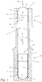
- Fig. 1 shows a longitudinal sectional view of an inventive socket system as part of a transport system not shown within a filling machine for capsules 1.
- the plug capsules 1 of which only a single copy is shown here for clarity, are used for example in the pharmaceutical sector or in the field of dietary supplements, and contain a drug preparation when filled. When completely filled and closed, they are intended to be swallowed by one person.
- Suitable capsule material are various materials such as hard gelatin, HPMC or the like, which dissolves after swallowing and releases the capsule contents.
- the two-piece plug-in capsule 1 is composed of two capsule halves, namely a capsule upper part 2 and a capsule lower part 3, wherein the capsule lower part 3 is inserted into the open side of the capsule upper part 2.
- the capsule shell 2 consists in the usual design of a hemispherical capsule bottom 14, to which an upper capsule wall 15 connects.
- the capsule upper part 2 is bounded by a peripheral edge 13 of the upper capsule wall 15.
- the capsule part 3 is constructed analogously to the capsule upper part 2 and consists of a hemispherical, dome-shaped capsule bottom 4, to which a cylindrical lower capsule wall 5 is connected.
- Capsule bottom 3 bounded by a peripheral edge 16 of the cylindrical capsule wall 5, wherein in the assembled state of capsule shell 2 and capsule part 3, a part of the cylindrical capsule wall 5 together with its peripheral edge 16 within the upper capsule wall 15 of the capsule shell 2 comes to rest.
- the socket system comprises at least one of the aforementioned capsule halves and at least one of these capsule half associated, in the manner described in more detail below geometrically matched to the capsule half capsule 21.
- this capsule lower part socket 6 and formed as a capsule part 3 capsule half or Kapseloberteilbuchse 17 and a be formed as a capsule shell 2 capsule half.
- the socket system comprises a respective capsule lower part 3, a capsule upper part 2 and two associated capsule sockets 21, namely a capsule bushing 21 designed as a capsule lower bushing 6 for receiving the capsule lower part 3 and a capsule bushing 21 designed as a capsule upper bushing 17 for receiving the capsule upper part 2 Practical operation, several such Buchsensysteme simultaneously or synchronously in use.
- the upper capsule bushing 21 designed as a capsule upper bushing 17 comprises a base body 7 with a receiving space 8 formed therein for the capsule upper part 2, this upper receiving space 8 having a bottom portion 9 associated with the capsule bottom 14 of the capsule shell 2 and a peripheral wall portion 10 for centering the capsule wall 15.
- the receiving space 8 is part of a stepped through hole, within which an annular support shoulder 19 connects to the receiving space 8.
- the circumferential edge 13 of the capsule shell 2 is in the inserted state on a support shoulder 19.
- the capsule base bushing 6 is positioned coaxially therewith and also comprises a base body 7 with a receiving space 8 formed therein for a capsule half, here for the capsule base 3.
- the lower receiving space 8 also comprises a peripheral wall section 10 and a bottom section 9 located below it , wherein this bottom portion 9 is associated with the capsule bottom 4 of the capsule lower part 3, and wherein the peripheral wall portion 10 of the centering of the capsule wall 5 of the capsule lower part 3 is used.
- the capsule part 3 is pulled out of the capsule upper part 2 and sucked into the receiving space 8 of the capsule base receiving 6 according to an arrow 20 until it is in its 3 'designated end position with its downwardly facing capsule bottom 4 on the opposite the peripheral wall portion 10 reduced in diameter bottom portion 9 comes to rest and is supported there in the rest state downwards in the axial direction.
- the capsule wall 5 of the capsule lower part 3 is centered by the peripheral wall portion 10 of the receiving space 8 and supported in the radial direction.
- the Kapseloberteilbuchse 17 is now removed in a manner not shown, so that the unit of capsule lower part 3 and lower capsule socket 6 is freely accessible from above.
- the capsule base 3 is then filled with the drug preparation, not shown, while it is held in the capsule lower part socket 6.
- the plug capsule 1 is closed.
- the unit from capsule upper part 2 and capsule upper part bushing 17 is moved back into the position again Fig. 1 method, and the capsule part 3 is pressed, for example by means of a punch, not shown, against the arrow 20 upwards back into the capsule upper part 2.
- Fig. 2 shows in a longitudinal sectional view of the capsule lower part socket 6 after Fig. 1 , From the synopsis with Fig. 1 It can be seen that the receiving space 8 formed coaxially in the base body 7 in addition to the already mentioned bottom portion 9 and the above-mentioned peripheral wall portion 10 also comprises a clamping portion 11 of reduced cross-section. The clamping portion 11 is located immediately above the bottom portion 9, thus directly adjoins this upward. In addition, there is the peripheral wall portion 10. However, it may also be appropriate that between the bottom portion 9 and the clamping portion 11 is still a part of the peripheral wall portion 10 is located.
- the geometry of the receiving space 8 is adapted to the geometry of the used for use capsule base 3, that the bottom portion 9 alone receives the hemispherical capsule bottom 4, while the overlying clamping portion 11 immediately above the capsule bottom 4 with the capsule wall 5 of the capsule base 6 in interaction occurs.
- the clamping portion 11 has a smaller free cross section than the peripheral wall portion 10 and optionally also has a smaller free cross section than the bottom portion 9.
- this is achieved by a specific clamping diameter D K of the clamping portion 11 as follows:
- the capsule part 3 has according to Fig. 1 along its capsule wall 5, but at least in the transition of the capsule wall 5 to the capsule bottom a Kapselteil malmesser Du on.
- For a free axial mobility of the capsule lower part 3 within the receiving space 8 of the free cross-section of the peripheral wall portion 10 is adapted thereto and also has the Kapselteil penmesser Du, with some radial clearance to the capsule wall 5 may be appropriate.
- the clamping portion 11 has a smaller free cross section than the peripheral wall portion 10 and also as the uppermost, adjacent to the clamping portion 11 portion of the bottom portion 9, including in the illustrated embodiment, the free clamping diameter D. K is smaller than the capsule part diameter D U.
- Fig. 3 shows in a longitudinal sectional view of the capsule upper part bushing 17 after Fig. 1 , From the synopsis with Fig. 2 It can be seen that the capsule shell bushing 17 after Fig. 3 in so far analogous to the capsule lower part socket 6 after Fig. 2 is constructed as that their receiving space 8 between the bottom portion 9 and the peripheral wall portion 10 has a clamping portion 11.
- the clamping portion 11 For the geometric configuration of the clamping portion 11, in particular with regard to its not shown here clamping diameter and its vote on the also not shown capsule diameter of the capsule shell 2 ( Fig. 1 ) applies in a similar manner to the capsule lower part 6 after Fig. 2 Said.
- the clamping portion 11 is formed by an inner side of the receiving opening 8 encircling annular bead 12.
- the annular bead 12 has in the preferred embodiment shown a rounded cross-section. But it can also be a cross section with corners, locking edges or the like appropriate.
- other embodiments of the clamping portion for example, by the arrangement of radially inwardly over the contour of the peripheral wall portion 10 protruding projections possible.
- the capsule lower part 3 immediately after pulling out of the capsule upper part 2 (FIG. Fig. 1 ) is held clamped or latched when hitting the bottom portion 9 by means of the clamping portion 11 and therefore can not jump back on impact with the bottom portion 9 of this (capsule jump).
- the clamping portion 11 presses into the capsule wall 5 of the capsule lower part 3 immediately above the capsule bottom, wherein the capsule wall easily yields radially inwardly under elastic deformation. It can be done undisturbed filling of the capsule part 3.
- a small impulse suffices from below, in order subsequently to release the filled capsule base 3 from its clamping or latching and to transport it back into the associated capsule upper part 2.
Landscapes
- Health & Medical Sciences (AREA)
- Chemical & Material Sciences (AREA)
- Medicinal Chemistry (AREA)
- Pharmacology & Pharmacy (AREA)
- Life Sciences & Earth Sciences (AREA)
- Animal Behavior & Ethology (AREA)
- General Health & Medical Sciences (AREA)
- Public Health (AREA)
- Veterinary Medicine (AREA)
- Medical Preparation Storing Or Oral Administration Devices (AREA)
- Medicinal Preparation (AREA)
- Manufacturing Of Micro-Capsules (AREA)
Abstract
Description
- Die Erfindung betrifft eine Kapselbuchse einer Füllmaschine für Steckkapseln mit den Merkmalen nach dem Oberbegriff des Anspruchs 1, sowie ein Buchsensystem umfassend eine solche Kapselbuchse.
- Insbesondere im Pharmabereich, aber auch im Bereich von Nahrungsergänzungsmitteln oder dgl. werden schluckbare Kapseln eingesetzt, in deren Innenraum Wirkstoffpräparate oder dgl. eingefüllt sind. Derartige Kapseln sind zweiteilig aus zwei Kapselhälften ausgeführt und bestehen aus einem Kapselunterteil sowie einem darauf aufgestecktem Kapseloberteil. Verbreitete Kapselmaterialien sind Hartgelatine, HPMC (Hydroxypropylmethylcellulose) oder dgl..
- Leerkapseln werden für die Befüllung im lose zusammengesteckten Zustand angeliefert und einem Kapseltransportsystem zugeführt. Dieses umfasst ein Segmentsystem mit Kapselbuchsen, namentlich mit Kapseloberteilbuchsen und mit Kapselbuchsen, wobei die lose zusammengesteckten Leerkapseln zunächst in den Kapseloberteilbuchsen zu liegen kommen. Hiervon ausgehend wird das Kapselunterteil aus dem Kapseloberteil beispielsweise mittels Unterdruck herausgezogen und in einen Aufnahmeraum der Kapselbuchse eingeführt. In der Kapselbuchse findet die Befüllung des Kapselunterteils statt. Hieran anschließend wird das Kapselunterteil beispielsweise mittels eines Stempels zur Kapseloberteilaufnahme gedrückt und dort in das Kapseloberteil abschließend eingeführt.
- Ein Umfangswandabschnitt des Aufnahmeraums dient einer losen Zentrierung der Kapselwand. Zu beachten ist hierbei, dass die einzelnen Kapselteile gewisse Streuungen beziehungsweise Toleranzen in ihren äußeren Abmaßen aufweisen. Außerdem kann es vorkommen, dass Kapseln mit zwar gleichen Nennmaßen, aber wegen unterschiedlicher Materialien mit unterschiedlichem mechanischem Verhalten verarbeitet werden sollen. Damit solche Kapselhälften frei in die jeweiligen Kapselbuchsen eingeführt und von dort auch wieder ausgestoßen werden können, ist im Stand der Technik eine entsprechend großzügige, spielbehaftete Dimensionierung des Aufnahmeraums insbesondere im Bereich seiner Umfangswand vorgesehen.
- In einem solchen Szenario besteht ein kritischer Effekt in den sogenannten Kapselsprüngen. Die Kapselunterteile werden dabei zunächst ordnungsgemäß in den Aufnahmeraum der jeweiligen Kapselbuchsen eingeführt bzw. eingesaugt, was mit hoher Geschwindigkeit geschieht. Nach Beendigung des impulsartigen Unterdruckstoßes können die Kapselunterteile vom Boden abprallen und dabei den genannten Kapselsprung ausführen. Der Sprung eines Kapselunterteils kann auch Rückwirkungen auf das darüber befindliche Kapseloberteil haben, welches dann seinerseits zu einem Kapselsprung neigt. Im weniger kritischen Fall geht hierdurch Zeit verloren, bis sich alle Kapselhälften in ihrer Lage beruhigt haben und die Befüllung begonnen werden kann. Im kritischeren Fall finden einzelne Kapselhälften nicht mehr in ihre vorgesehene Position zurück oder springen sogar aus ihrer Buchse heraus. In der Folge kommt es zur Produktion von Ausschuss oder sogar zum Produktionsstillstand. Der genannte Effekt kann durch eine enger tolerierte Anpassung der Buchsengeometrie an die jeweils zu verarbeitenden Kapseltypen gemindert werden. Das setzt aber voraus, dass für jeden konkreten Kapseltyp ein angepasster Satz von Kapselbuchsen vorhanden ist. Eine universelle Einsetzbarkeit für verschiedene Kapseln innerhalb eines bestimmten Durchmesserbereichs geht damit verloren, wobei außerdem eine vollständige Vermeidung der Kapselsprünge nicht gelingt.
- Der Erfindung liegt die Aufgabe zugrunde, eine gattungsgemäße Kapselbuchse derart weiterzubilden, dass ihre Betriebssicherheit gesteigert ist.
- Diese Aufgabe wird durch eine Kapselbuchse mit den Merkmalen des Anspruchs 1 gelöst.
- Der Erfindung liegt des Weiteren die Aufgabe zugrunde, ein Buchsensystem umfassend eine Kapselbuchse und eine Kapselhälfte derart aufeinander abzustimmen, dass ein leichtes Ein- und Ausfädeln und dennoch ein zuverlässiges Halten der Kapselhälfte in der Kapselbuchse erreicht ist.
- Diese Aufgabe wird durch ein Buchsensystem mit den Merkmalen des Anspruchs 8 gelöst.
- Nach der Erfindung ist eine Kapselbuchse vorgesehen, bei der der Aufnahmeraum zwischen dem Bodenabschnitt und dem Umfangswandabschnitt einen Klemmabschnitt aufweist, wobei der Klemmabschnitt einen kleineren freien Querschnitt als der Umfangswandabschnitt aufweist. In einem entsprechenden Buchsensystem, welches eine solche Kapselbuchse und eine passende Kapselhälfte umfasst, weist der Klemmabschnitt des Aufnahmeraums einen freien Klemmdurchmesser auf, welcher kleiner ist als der Kapselteildurchmesser der zugeordneten Kapselhälfte. Mit anderen Worten wird also nicht der gesamte Aufnahmeraum in seinem Querschnitt soweit verkleinert, dass die Kapselhälfte klemmend geführt und gehalten wird. Vielmehr sieht die Erfindung eine nur lokale Klemmung mittels des Klemmabschnittes vor. Hierdurch kann die Kapsel bzw. die Kapselhälfte frei eingeführt bzw. angesaugt werden, während die Klemmwirkung des Klemmabschnittes nur im Bereich der Endposition eintritt, in der die Kapselhälfte ordnungsgemäß positioniert ist. Umgekehrt reicht es nach dem Füllvorgang aus, das Kapselunterteil mit einem nur kurzen Stoß aus seiner Klemmung zu befreien, woran sich dann eine freie, unbehinderte Bewegung zur Einführung in das Kapseloberteil anschließen kann. Sinngemäß das Gleiche gilt auch für den dann nachfolgenden Ausstoß der fertig befüllten und zusammengesteckten Kapsel. Die örtlich im Klemmabschnitt begrenzte Klemmung stellt sicher, dass die jeweilige Kapselhälfte auch bei sehr schnell getakteten Zyklen und hoher Bewegungsgeschwindigkeit nicht wieder aus ihrer Zielposition zurückprallt. Vielmehr kann erreicht werden, dass die Kapselhälften bereits nach sehr kurzer Zeit ihre Füllposition eingenommen haben und für den sich anschließenden Füllvorgang auch beibehalten. Kapselsprünge sind zuverlässig vermieden, sodass die Betriebssicherheit deutlich gesteigert ist. Freie Beweglichkeit und lokal begrenzte Klemmwirkung funktionieren innerhalb einer beträchtlichen Bandbreite von Maßtoleranzen und mechanisch unterschiedlichen Verhaltensweisen verschiedener Kapseln, so dass eine spezifische Anpassung der Kapselbuchsen an bestimmte Kapseltypen kaum oder sogar gar nicht erforderlich ist.
- In vorteilhafter Weiterbildung der Erfindung weist der Klemmabschnitt auch einen kleineren freien Querschnitt als der Bodenabschnitt auf. Hierbei wird eine besondere mechanische Eigenschaft des Kapselunterteils genutzt: In radialer Richtung ist der kalottenförmige Kapselboden steifer als die etwa zylindrische Kapselwand. Der Kapselboden wird also beim Einführen zunächst durch den verengten Klemmabschnitt gezwängt, kann sich dann aber im größeren Querschnitt des Bodenabschnitts wieder etwas aufweiten. Der Klemmabschnitt umgreift mit seinem kleineren freien Querschnitt nur noch die weichere, nachgiebigere Kapselwand. Hierdurch entsteht über eine reine Klemmung hinausgehend eine Verrastung nach dem Prinzip eines Druckknopfs. Es wird eine präzise definierte Lagepositionierung der Kapselhälfte erreicht, die nur über einen kleinen axialen Weg wirkt und deshalb die freie Beweglichkeit der Kapselhälfte beim Ein- oder Ausbringen praktisch nicht beeinträchtigt. Insbesondere grenzt der Klemmabschnitt unmittelbar an den Bodenabschnitt an. Dadurch ist die axiale Lage der Kapselhälfte eindeutig und praktisch spielfrei in beide Richtungen, also nach oben und nach unten definiert.
- Es kann zweckmäßig sein, einzelne radiale Vorsprünge oder dergleichen auf der Innenwand der Aufnahmeöffnung vorzusehen, um hierdurch den Klemmabschnitt zu bilden. In einer bevorzugten Ausführungsform ist der Klemmabschnitt durch einen innenseitig der Aufnahmeöffnung umlaufenden Ringwulst gebildet und weist insbesondere einen gerundeten Querschnitt auf. Mit der Erzielung der gewünschten Klemm- bzw. Rastwirkung gehen hierbei nur sehr kleine örtliche Flächenpressungen einher, welche auf die Kapselwand wirken. Der gerundete Querschnitt erlaubt ein schädigungsfreies Ein- und Ausfädeln der Kapselhälfte.
- In einer vorteilhaften Ausführungsform ist die Kapselbuchse eine Kapselunterteilbuchse zur Aufnahme einer als Kapselunterteil ausgebildeten Kapselhälfte. Hierdurch kann zuverlässig vermieden werden, dass das mit hoher Geschwindigkeit eintretende Kapselunterteil vom Bodenabschnitt zurückprallt. Alternativ oder zusätzlich kann es zweckmäßig sein, dass die Kapselbuchse eine Kapseloberteilbuchse zur Aufnahme einer als Kapseloberteil ausgebildeten Kapselhälfte ist. Rückwirkungen vom Kapselunterteil oder andere Einflüsse können nicht mehr dazu führen, dass das Kapseloberteil einen Sprung ausführt.
- Ein Ausführungsbeispiel der Erfindung ist nachfolgend anhand der Zeichnung näher beschrieben. Es zeigen:
- Fig. 1
- in einer Längsschnittdarstellung ein erfindungsgemäßes Buchsensystem mit einer Steckkapsel, mit einer Kapselunterteilbuchse und mit einer Kapseloberteilbuchse zur Handhabung von Kapseloberteil und Kapselunterteil beim Füllen,
- Fig. 2
- in einer Längsschnittdarstellung die Kapselunterteilbuchse nach
Fig. 1 mit Einzelheiten zu ihrer geometrischen Ausgestaltung, - Fig. 3
- in einer Längsschnittdarstellung die Kapseloberteilbuchse nach
Fig. 1 mit Einzelheiten zu ihrer geometrischen Ausgestaltung, und - Fig. 4
- in einer vergrößerten Darstellung die in den
Fig. 2 und 3 mit IV gekennzeichnete Einzelheit betreffend die Querschnittsform eines Ringwulstes zur Bildung des Klemmabschnittes. -
Fig. 1 zeigt in einer Längsschnittdarstellung ein erfindungsgemäßes Buchsensystem als Teil eines nicht näher dargestellten Transportsystems innerhalb einer Füllmaschine für Steckkapseln 1. Die Steckkapseln 1, von denen hier zur besseren Übersicht nur ein einziges Exemplar gezeigt ist, werden beispielsweise im Pharmabereich oder im Bereich von Nahrungsergänzungsmitteln eingesetzt, und enthalten im befüllten Zustand ein Wirkstoffpräparat. Im fertig befüllten und verschlossenen Zustand sind sie zum Verschlucken durch eine Person vorgesehen. Als Kapselmaterial kommen verschiedene Materialen wie Hartgelatine, HPMC oder dgl. in Betracht, welches sich nach dem Verschlucken auflöst und den Kapselinhalt freigibt. - Die zweiteilige Steckkapsel 1 ist aus zwei Kapselhälften, nämlich einem Kapseloberteil 2 und einem Kapselunterteil 3 zusammengesetzt, wobei das Kapselunterteil 3 in die offene Seite des Kapseloberteils 2 eingeschoben ist. Das Kapseloberteil 2 besteht in üblicher Bauform aus einem halbkugeligen Kapselboden 14, an die sich eine obere Kapselwand 15 anschließt. An seiner offenen Seite ist das Kapseloberteil 2 durch eine umlaufende Kante 13 der oberen Kapselwand 15 begrenzt. Das Kapselunterteil 3 ist analog zum Kapseloberteil 2 aufgebaut und besteht aus einem halbkugeligen, kalottenförmigen Kapselboden 4, an den sich eine zylindrische untere Kapselwand 5 anschließt. An seiner dem Kapseloberteil 2 zugewandten und dort eingeführten Seite ist das Kapselunterteil 3 mit einer umlaufenden Kante 16 der zylindrischen Kapselwand 5 begrenzt, wobei im zusammengesteckten Zustand von Kapseloberteil 2 und Kapselunterteil 3 ein Teil der zylindrischen Kapselwand 5 samt ihrer umlaufenden Kante 16 innerhalb der oberen Kapselwand 15 des Kapseloberteils 2 zu liegen kommt.
- Das erfindungsgemäße Buchsensystem umfasst zumindest eine der vorgenannten Kapselhälften und zumindest eine dieser Kapselhälfte zugeordnete, in nachstehend näher beschriebener Weise geometrisch auf die Kapselhälfte abgestimmte Kapselbuchse 21. Nach der Erfindung kann dies eine Kapselunterteilbuchse 6 und eine als Kapselunterteil 3 ausgebildete Kapselhälfte oder eine Kapseloberteilbuchse 17 und eine als Kapseloberteil 2 ausgebildete Kapselhälfte sein. Im gezeigten bevorzugten Ausführungsbeispiel umfasst das erfindungsgemäße Buchsensystem je ein Kapselunterteil 3, ein Kapseloberteil 2 sowie zwei zugeordnete Kapselbuchsen 21, nämlich eine als Kapselunterteilbuchse 6 ausgebildete Kapselbuchse 21 zur Aufnahme des Kapselunterteils 3 und eine als Kapseloberteilbuchse 17 ausgebildete Kapselbuchse 21 zur Aufnahme des Kapseloberteils 2. Im praktischen Betrieb sind mehrere solcher Buchsensysteme gleichzeitig bzw. synchron im Einsatz.
- Leere Steckkapseln 1 werden in einem Zustand angeliefert, bei denen die Kapselunterteile 3 in jeweils zugeordnete Kapseloberteile 2 lose eingesteckt sind. In diesem Zustand wird eine einzelne Kapsel 1 in die Kapseloberteilbuchse 17 von oben entsprechend einem Pfeil 18 eingeführt. Die als Kapseloberteilbuchse 17 ausgeführte obere Kapselbuchse 21 umfasst einen Grundkörper 7 mit einem darin ausgeformten Aufnahmeraum 8 für das Kapseloberteil 2, wobei dieser obere Aufnahmeraum 8 einen dem Kapselboden 14 des Kapseloberteils 2 zugeordneten Bodenabschnitt 9 und einen Umfangswandabschnitt 10 zur Zentrierung der Kapselwand 15 aufweist. Der Aufnahmeraum 8 ist Teil einer gestuften Durchgangsbohrung, innerhalb derer sich an den Aufnahmeraum 8 ein ringförmiger Auflageabsatz 19 anschließt. Die umlaufende Kante 13 des Kapseloberteils 2 liegt im eingeführten Zustand auf einem Auflageabsatz 19 auf.
- Unterhalb der Kapseloberteilbuchse 17 ist die Kapselunterteilbuchse 6 koaxial dazu positioniert und umfasst ebenfalls einen Grundkörper 7 mit einem darin ausgebildeten Aufnahmeraum 8 für eine Kapselhälfte, hier für das Kapselunterteil 3. Auch der untere Aufnahmeraum 8 umfasst einen Umfangswandabschnitt 10 und einen hier allerdings darunter befindlichen Bodenabschnitt 9, wobei dieser Bodenabschnitt 9 dem Kapselboden 4 des Kapselunterteils 3 zugeordnet ist, und wobei der Umfangswandabschnitt 10 der Zentrierung der Kapselwand 5 des Kapselunterteils 3 dient.
- Beispielsweise mittels Vakuum oder dgl. wird das Kapselunterteil 3 aus dem Kapseloberteil 2 herausgezogen und in den Aufnahmeraum 8 der Kapselunterteilaufnahme 6 entsprechend einem Pfeil 20 eingesaugt, bis es in seiner mit 3' bezeichneten Endposition mit seinem nach unten weisenden Kapselboden 4 auf dem gegenüber dem Umfangswandabschnitt 10 im Durchmesser verringerten Bodenabschnitt 9 zu liegen kommt und im Ruhezustand dort in axialer Richtung nach unten abgestützt wird. Hierbei wird die Kapselwand 5 des Kapselunterteils 3 durch den Umfangswandabschnitt 10 des Aufnahmeraums 8 zentriert und in radialer Richtung gestützt.
- Die Kapseloberteilbuchse 17 wird nun in nicht dargestellter Weise entfernt, so dass die Einheit aus Kapselunterteil 3 und Kapselunterteilbuchse 6 von oben frei zugänglich ist. Das Kapselunterteil 3 wird daraufhin mit dem nicht dargestellten Wirkstoffpräparat befüllt, während es in der Kapselunterteilbuchse 6 gehalten ist. Nach der Befüllung erfolgt ein Verschließen der Steckkapsel 1. Hierzu wird die Einheit aus Kapseloberteil 2 und Kapseloberteilbuchse 17 wieder zurück in die Position nach
Fig. 1 verfahren, und das Kapselunterteil 3 wird beispielsweise mittels eines nicht dargestellten Stempels entgegen dem Pfeil 20 nach oben zurück in das Kapseloberteil 2 hineingedrückt. -
Fig. 2 zeigt in einer Längsschnittdarstellung die Kapselunterteilbuchse 6 nachFig. 1 . Aus der Zusammenschau mitFig. 1 ist erkennbar, dass der im Grundkörper 7 koaxial dazu ausgebildete Aufnahmeraum 8 neben dem bereits erwähnten Bodenabschnitt 9 und dem ebenfalls erwähnten Umfangswandabschnitt 10 noch einen Klemmabschnitt 11 mit verringertem Querschnitt umfasst. Der Klemmabschnitt 11 befindet sich unmittelbar oberhalb des Bodenabschnittes 9, grenzt also unmittelbar an diesen nach oben an. Darüber befindet sich der Umfangswandabschnitt 10. Es kann aber auch zweckmäßig sein, dass sich zwischen dem Bodenabschnitt 9 und dem Klemmabschnitt 11 noch ein Teil des Umfangswandabschnittes 10 befindet. Jedenfalls ist die Geometrie des Aufnahmeraums 8 derart an die Geometrie des zum Einsatz kommenden Kapselunterteils 3 angepasst, dass der Bodenabschnitt 9 allein den halbkugeligen Kapselboden 4 aufnimmt, während der darüber befindliche Klemmabschnitt 11 unmittelbar oberhalb des Kapselbodens 4 mit der Kapselwand 5 des Kapselunterteils 6 in Wechselwirkung tritt. - Weiter ergibt sich aus der Zusammenschau der
Fig. 1 und2 , dass der Klemmabschnitt 11 einen kleineren freien Querschnitt als der Umfangswandabschnitt 10 hat und optional auch einen kleineren freien Querschnitt als der Bodenabschnitt 9 aufweist. Im vorliegenden Fall ist dies durch einen bestimmten Klemmdurchmesser DK des Klemmabschnitts 11 wie folgt erreicht: Das Kapselunterteil 3 weist gemäßFig. 1 entlang seiner Kapselwand 5, zumindest aber im Übergang der Kapselwand 5 zum Kapselboden einen Kapselteildurchmesser Du auf. Für eine freie axiale Beweglichkeit des Kapselunterteils 3 innerhalb des Aufnahmeraums 8 ist der freie Querschnitt des Umfangswandabschnittes 10 hieran angepasst und weist ebenfalls den Kapselteildurchmesser Du auf, wobei etwas radiales Spiel zur Kapselwand 5 zweckmäßig sein kann. Das Gleiche gilt auch für den obersten Bereich des Bodenabschnitts 9. Jedenfalls weist der Klemmabschnitt 11 einen kleineren freien Querschnitt als der Umfangswandabschnitt 10 und auch als der oberste, an den Klemmabschnitt 11 angrenzende Bereich des Bodenabschnitts 9 auf, wozu im gezeigten Ausführungsbeispiel der freie Klemmdurchmesser DK kleiner ist als der Kapselteildurchmesser DU. -
Fig. 3 zeigt in einer Längsschnittdarstellung die Kapseloberteilbuchse 17 nachFig. 1 . Aus der Zusammenschau mitFig. 2 ist erkennbar, dass die Kapseloberteilbuchse 17 nachFig. 3 insoweit analog zur Kapselunterteilbuchse 6 nachFig. 2 aufgebaut ist, als dass auch ihr Aufnahmeraum 8 zwischen dem Bodenabschnitt 9 und dem Umfangswandabschnitt 10 einen Klemmabschnitt 11 aufweist. Für die geometrische Ausgestaltung des Klemmabschnittes 11 insbesondere hinsichtlich seines hier nicht eingezeichneten Klemmdurchmessers und dessen Abstimmung auf den ebenfalls nicht eingezeichneten Kapselteildurchmesser des Kapseloberteils 2 (Fig. 1 ) gilt in analoger Weise das zur Kapselunterteilbuchse 6 nachFig. 2 Gesagte. - In den
Figuren 2 und 3 ist jeweils eine Einzelheit mit IV gekennzeichnet, welche vergrößert inFig. 4 dargestellt ist. Demnach ist der Klemmabschnitt 11 durch einen innenseitig der Aufnahmeöffnung 8 umlaufenden Ringwulst 12 gebildet. Der Ringwulst 12 weist im gezeigten bevorzugten Ausführungsbeispiel einen gerundeten Querschnitt auf. Es kann aber auch ein Querschnitt mit Ecken, Rastkanten oder dergleichen zweckmäßig sein. Außerdem sind im Rahmen der Erfindung andere Ausführungen des Klemmabschnitts beispielsweise durch die Anordnung von radial nach innen über die Kontur des Umfangswandabschnitts 10 hervorstehenden Vorsprüngen möglich. - Jedenfalls wird durch die erfindungsgemäße Ausgestaltung erreicht, dass das Kapselunterteil 3 unmittelbar nach dem Herausziehen aus dem Kapseloberteil 2 (
Fig. 1 ) beim Auftreffen auf den Bodenabschnitt 9 mittels des Klemmabschnittes 11 klemmend bzw. rastend gehalten wird und deshalb nicht beim Aufprall auf den Bodenabschnitt 9 von diesem zurückspringen kann (Kapselsprung). Hierzu drückt sich der Klemmabschnitt 11 in die Kapselwand 5 des Kapselunterteils 3 unmittelbar oberhalb dessen Kapselboden ein, wobei die Kapselwand radial nach innen unter elastischer Verformung leicht nachgibt. Es kann eine ungestörte Befüllung des Kapselunterteils 3 erfolgen. Umgekehrt reicht ein geringer Impuls von unten aus, um anschließend das befüllte Kapselunterteil 3 aus seiner Klemmung bzw. Rastung zu befreien und wieder zurück in das zugehörige Kapseloberteil 2 zu befördern. Sinngemäß das Gleiche gilt auch für das Kapseloberteil 2, welches rastend in der Kapseloberteilbuchse 17 gehalten und am Springen gehindert wird. Ein Hinausdrücken der komplettierten Steckkapsel 1 ist dennoch mittels eines nur geringen Stoßes oder Impulses möglich.
Claims (8)
- Kapselbuchse (21) einer Füllmaschine für Steckkapseln (1), wobei die Steckkapseln (1) zwei Kapselhälften mit jeweils einem Kapselboden (4, 14) und mit einer Kapselwand (5, 15) aufweisen, wobei die Kapselbuchse (21) einen Grundkörper (7) mit einem darin ausgeformten Aufnahmeraum (8) für die Kapselhälfte umfasst, und wobei der Aufnahmeraum (8) einen dem jeweiligen Kapselboden (4, 14) zugeordneten Bodenabschnitt (9) und einen Umfangswandabschnitt (10) zur Zentrierung der Kapselwand (5, 15) aufweist,
dadurch gekennzeichnet, dass der Aufnahmeraum (8) zwischen dem Bodenabschnitt (9) und dem Umfangswandabschnitt (10) einen Klemmabschnitt (11) aufweist, wobei der Klemmabschnitt (11) einen kleineren freien Querschnitt als der Umfangswandabschnitt (10) aufweist. - Kapselbuchse nach Anspruch 1,
dadurch gekennzeichnet, dass der Klemmabschnitt (11) einen kleineren freien Querschnitt als der Bodenabschnitt (9) aufweist. - Kapselbuchse nach Anspruch 1 oder 2,
dadurch gekennzeichnet, dass der Klemmabschnitt (11) unmittelbar an den Bodenabschnitt (9) angrenzt. - Kapselbuchse nach einem der Ansprüche 1 bis 3,
dadurch gekennzeichnet, dass der Klemmabschnitt (11) durch einen innenseitig der Aufnahmeöffnung (8) umlaufenden Ringwulst (12) gebildet ist. - Kapselbuchse nach einem der Ansprüche 1 bis 4,
dadurch gekennzeichnet, dass der Ringwulst (12) einen gerundeten Querschnitt aufweist. - Kapselbuchse nach einem der Ansprüche 1 bis 5,
dadurch gekennzeichnet, dass die Kapselbuchse (21) eine Kapselunterteilbuchse (6) zur Aufnahme einer als Kapselunterteil (3) ausgebildeten Kapselhälfte ist. - Kapselbuchse nach einem der Ansprüche 1 bis 6,
dadurch gekennzeichnet, dass die Kapselbuchse (21) eine Kapseloberteilbuchse (17) zur Aufnahme einer als Kapseloberteil (2) ausgebildeten Kapselhälfte ist. - Buchsensystem umfassend eine Kapselbuchse (21) und eine Kapselhälfte nach einem der Ansprüche 1 bis 7, wobei die Kapselhälfte im Übergangsbereich von ihrem Kapselboden (4) zu ihrer Kapselwand (5) einen Kapselteildurchmesser (DU) aufweist,
dadurch gekennzeichnet, dass der Klemmabschnitt (11) einen freien Klemmdurchmesser (DK) aufweist, welcher kleiner ist als der Kapselteildurchmesser (DU).
Priority Applications (8)
| Application Number | Priority Date | Filing Date | Title |
|---|---|---|---|
| PL18164596.1T PL3545937T3 (pl) | 2018-03-28 | 2018-03-28 | <div>Tuleja kapsułkowa do kapsułek wtykanych i układ tulejowy</div> |
| ES18164596T ES2924175T3 (es) | 2018-03-28 | 2018-03-28 | Manguito para cápsula para cápsulas ensamblables y sistema de manguitos |
| SI201830730T SI3545937T1 (sl) | 2018-03-28 | 2018-03-28 | Puša kapsule za vtične kapsule in sistem puš |
| DK18164596.1T DK3545937T3 (da) | 2018-03-28 | 2018-03-28 | Kapselbøsning til stikkapsler og bøsningssystem |
| EP18164596.1A EP3545937B1 (de) | 2018-03-28 | 2018-03-28 | Kapselbuchse für steckkapseln und buchsensystem |
| US16/366,601 US11369546B2 (en) | 2018-03-28 | 2019-03-27 | Capsule socket for two-piece capsules and socket system |
| CA3038224A CA3038224A1 (en) | 2018-03-28 | 2019-03-28 | Capsule socket for two-piece capsules and socket system |
| CN201910243753.8A CN110314096B (zh) | 2018-03-28 | 2019-03-28 | 用于插塞胶囊的胶囊套管和套管系统 |
Applications Claiming Priority (1)
| Application Number | Priority Date | Filing Date | Title |
|---|---|---|---|
| EP18164596.1A EP3545937B1 (de) | 2018-03-28 | 2018-03-28 | Kapselbuchse für steckkapseln und buchsensystem |
Publications (2)
| Publication Number | Publication Date |
|---|---|
| EP3545937A1 true EP3545937A1 (de) | 2019-10-02 |
| EP3545937B1 EP3545937B1 (de) | 2022-05-18 |
Family
ID=61832403
Family Applications (1)
| Application Number | Title | Priority Date | Filing Date |
|---|---|---|---|
| EP18164596.1A Active EP3545937B1 (de) | 2018-03-28 | 2018-03-28 | Kapselbuchse für steckkapseln und buchsensystem |
Country Status (8)
| Country | Link |
|---|---|
| US (1) | US11369546B2 (de) |
| EP (1) | EP3545937B1 (de) |
| CN (1) | CN110314096B (de) |
| CA (1) | CA3038224A1 (de) |
| DK (1) | DK3545937T3 (de) |
| ES (1) | ES2924175T3 (de) |
| PL (1) | PL3545937T3 (de) |
| SI (1) | SI3545937T1 (de) |
Cited By (1)
| Publication number | Priority date | Publication date | Assignee | Title |
|---|---|---|---|---|
| EP3861974A1 (de) * | 2020-02-07 | 2021-08-11 | Harro Höfliger Verpackungsmaschinen GmbH | Kapselverschliesseinrichtung zum verschliessen zweiteiliger kapseln |
Families Citing this family (2)
| Publication number | Priority date | Publication date | Assignee | Title |
|---|---|---|---|---|
| EP4115871A1 (de) * | 2021-07-09 | 2023-01-11 | Harro Höfliger Verpackungsmaschinen GmbH | Übergabevorrichtung für eine kapsel und kapselfüllmaschine mit übergabevorrichtung |
| US12509264B2 (en) * | 2024-06-19 | 2025-12-30 | Phillip J Case | Capsule orientation and loading sheet for manual capsule filling machines |
Citations (4)
| Publication number | Priority date | Publication date | Assignee | Title |
|---|---|---|---|---|
| US6367228B1 (en) * | 1999-03-13 | 2002-04-09 | Robert Bosch Gmbh | Capsule part carrier in a filling and sealing machine for two-part capsules |
| WO2008141861A1 (de) * | 2007-05-22 | 2008-11-27 | Robert Bosch Gmbh | Kapsel zur aufnahme eines mediums sowie verfahren zur herstellung einer derartigen kapsel |
| DE102010038544A1 (de) * | 2009-10-19 | 2011-04-21 | Robert Bosch Gmbh | Sensorvorrichtung für eine Verpackungsmaschine |
| DE202011003680U1 (de) * | 2011-03-08 | 2011-06-09 | Harro Höfliger Verpackungsmaschinen GmbH, 71573 | Kapselsortierblock und Sortiereinrichtung für unorientierte Kapseln |
Family Cites Families (30)
| Publication number | Priority date | Publication date | Assignee | Title |
|---|---|---|---|---|
| US1073286A (en) * | 1908-09-23 | 1913-09-16 | Joseph Percy Remington | Capsule-filling mechanism. |
| US1147512A (en) * | 1914-07-03 | 1915-07-20 | William John Kirkland | Capsule-filler. |
| US1567639A (en) * | 1922-07-10 | 1925-12-29 | Eastman Louis Ralph | Capsule-filling machine |
| US1993716A (en) * | 1930-01-02 | 1935-03-05 | Lilly Co Eli | Capsule filling machine |
| US2742749A (en) * | 1953-06-04 | 1956-04-24 | Kurt J Huttlinger | Capsule-filler |
| US3324902A (en) * | 1965-05-26 | 1967-06-13 | Bartelt Engineering Co Inc | Method of filling capsules |
| US3501894A (en) * | 1966-03-15 | 1970-03-24 | Sankyo Co | Capsule charging system |
| US3552095A (en) * | 1968-04-18 | 1971-01-05 | Lilly Co Eli | Manual capsule filling apparatus |
| US3675390A (en) * | 1970-07-31 | 1972-07-11 | Ansaks Ind Inc | Capsule filling apparatus |
| JPS536916B2 (de) * | 1973-11-15 | 1978-03-13 | ||
| US4040536A (en) * | 1975-05-05 | 1977-08-09 | R. P. Scherer Corporation | Locking hard gelatin capsule |
| DE2722807A1 (de) * | 1977-05-20 | 1978-11-23 | Capsugel Ag | Verfahren zum herstellen einer mit viskosem stoff gefuellten steckkapsel |
| IT1171950B (it) * | 1983-09-30 | 1987-06-10 | Mg 2 Spa | Procedimento per l'alimentazione, l'orientamento, il riempimento, la chiusura e l'espulsione di capsule ed impianto che attua tale procedimento |
| US5081822A (en) * | 1990-02-01 | 1992-01-21 | Warner-Lambert Company | Automatic caplet filler |
| AU650113B2 (en) * | 1991-04-05 | 1994-06-09 | Eli Lilly And Company | Sustained release capsule and formulations |
| US5321932A (en) * | 1992-02-26 | 1994-06-21 | Professional Compounding Centers Of America, Inc. | Capsule handling system |
| IT1266251B1 (it) * | 1993-02-16 | 1996-12-27 | Ima Spa | Dispositivo per l'orientamento del fondello e del coperchio di capsule di gelatina dura e per l'alimentazione di questi opercoli ad |
| CN100548260C (zh) * | 2002-07-05 | 2009-10-14 | 盐野义胶囊股份有限公司 | 胶囊填充封口装置 |
| US7343724B1 (en) * | 2004-11-10 | 2008-03-18 | Mallinckrodt Inc. | Semi-automated custom capsule dispensing and assembly machine and method |
| DE102005001332A1 (de) * | 2005-01-11 | 2006-07-20 | Boehringer Ingelheim Pharma Gmbh & Co. Kg | Zweiteilige Kapsel mit Vorverschluss zur Aufnahme von pharmazeutischen Zubereitungen für Pulverinhalatoren |
| DE102005057393A1 (de) * | 2005-11-30 | 2007-05-31 | Robert Bosch Gmbh | Wiegevorrichtung einer Verpackungsmaschine |
| NL1033047C2 (nl) * | 2006-12-13 | 2008-06-16 | Pharmachemie Bv | Capsule, gevuld met een medicijn, in het bijzonder een inhaleerbaar medicijn. |
| DE102008013403A1 (de) * | 2008-03-10 | 2009-09-17 | Robert Bosch Gmbh | Kapselträgeranordnung für Füll- und Verschließmaschinen |
| CN101461760B (zh) * | 2008-12-30 | 2012-01-18 | 杨松 | 振动式胶囊自动调头加料机构 |
| JP5033147B2 (ja) * | 2009-02-04 | 2012-09-26 | 株式会社 ノサカテック | 容器蓋体の結合方法 |
| US8596025B2 (en) * | 2009-06-01 | 2013-12-03 | Patheon International Ag | Systems and methods for capsule pressure-relief |
| US8790692B2 (en) * | 2009-09-09 | 2014-07-29 | Patheon Pharmaceuticals Inc. | Break resistant gel capsule |
| ES2776003T3 (es) * | 2011-05-27 | 2020-07-28 | Boehringer Ingelheim Int | Inhalador y cápsula para un inhalador |
| DE102012212033A1 (de) * | 2012-07-10 | 2014-01-16 | Robert Bosch Gmbh | Kapselwägevorrichtung, Kapselfüllmaschine und Verfahren zum Wiegen einer Kapsel |
| EP3246000A1 (de) * | 2016-05-18 | 2017-11-22 | Capsugel Belgium NV | Trennbare kapsel für sprenkleranwendungen |
-
2018
- 2018-03-28 SI SI201830730T patent/SI3545937T1/sl unknown
- 2018-03-28 DK DK18164596.1T patent/DK3545937T3/da active
- 2018-03-28 PL PL18164596.1T patent/PL3545937T3/pl unknown
- 2018-03-28 ES ES18164596T patent/ES2924175T3/es active Active
- 2018-03-28 EP EP18164596.1A patent/EP3545937B1/de active Active
-
2019
- 2019-03-27 US US16/366,601 patent/US11369546B2/en active Active
- 2019-03-28 CN CN201910243753.8A patent/CN110314096B/zh active Active
- 2019-03-28 CA CA3038224A patent/CA3038224A1/en active Pending
Patent Citations (4)
| Publication number | Priority date | Publication date | Assignee | Title |
|---|---|---|---|---|
| US6367228B1 (en) * | 1999-03-13 | 2002-04-09 | Robert Bosch Gmbh | Capsule part carrier in a filling and sealing machine for two-part capsules |
| WO2008141861A1 (de) * | 2007-05-22 | 2008-11-27 | Robert Bosch Gmbh | Kapsel zur aufnahme eines mediums sowie verfahren zur herstellung einer derartigen kapsel |
| DE102010038544A1 (de) * | 2009-10-19 | 2011-04-21 | Robert Bosch Gmbh | Sensorvorrichtung für eine Verpackungsmaschine |
| DE202011003680U1 (de) * | 2011-03-08 | 2011-06-09 | Harro Höfliger Verpackungsmaschinen GmbH, 71573 | Kapselsortierblock und Sortiereinrichtung für unorientierte Kapseln |
Cited By (1)
| Publication number | Priority date | Publication date | Assignee | Title |
|---|---|---|---|---|
| EP3861974A1 (de) * | 2020-02-07 | 2021-08-11 | Harro Höfliger Verpackungsmaschinen GmbH | Kapselverschliesseinrichtung zum verschliessen zweiteiliger kapseln |
Also Published As
| Publication number | Publication date |
|---|---|
| DK3545937T3 (da) | 2022-08-15 |
| PL3545937T3 (pl) | 2022-11-21 |
| EP3545937B1 (de) | 2022-05-18 |
| ES2924175T3 (es) | 2022-10-05 |
| SI3545937T1 (sl) | 2022-11-30 |
| US11369546B2 (en) | 2022-06-28 |
| US20190298614A1 (en) | 2019-10-03 |
| CN110314096B (zh) | 2022-06-14 |
| CA3038224A1 (en) | 2019-09-28 |
| CN110314096A (zh) | 2019-10-11 |
Similar Documents
| Publication | Publication Date | Title |
|---|---|---|
| EP0361028B1 (de) | Doppelkammerbehälter | |
| EP3545937B1 (de) | Kapselbuchse für steckkapseln und buchsensystem | |
| EP3380060B1 (de) | Vorrichtung und verfahren zum ausstossen zumindest einer kapsel aus einem kapselhalter | |
| DE102007039368A1 (de) | Einfallkern für ein Kunststoffspritzwerkzeug | |
| EP3044118B1 (de) | Behälterdose und halteeinrichtung | |
| EP3771078B1 (de) | Kranzanordnungs- und -fügevorrichtung sowie kranzanordnungs- und -fügeverfahren | |
| EP3037016B1 (de) | Bürstenherstellungsmaschine und verfahren zum einbringen von borstenbündeln in öffnungen eines bündelträgers | |
| EP2872417B1 (de) | Behälterdose, halteeinrichtung und verfahren zum bereitstellen einer behälterdose | |
| DE102015119174A1 (de) | Umformvorrichtung sowie Verfahren zum Umformen eines Innenrandes eines Rondenrings | |
| DE1750168A1 (de) | Ventil zum Verschliessen einer Fuelloeffnung in der Wandung der Treibmittelkammer eines Behaelters | |
| DE102013211305A1 (de) | Tablettenpresse und Verfahren zum Herstellen einer Tablette | |
| DE3629608A1 (de) | Elektrischer mehrfachsteckverbinder | |
| DE2944827A1 (de) | Vorrichtung zum ausrichten von kapseln | |
| DE69010374T2 (de) | Vorschubeinrichtung für einen stangenartigen Gegenstand. | |
| DE1270785B (de) | Vorrichtung zum Herstellen eines Puppenkopfes | |
| EP3861974B1 (de) | Kapselverschliesseinrichtung zum verschliessen zweiteiliger kapseln | |
| EP4115871A1 (de) | Übergabevorrichtung für eine kapsel und kapselfüllmaschine mit übergabevorrichtung | |
| DE4421982C2 (de) | Vorrichtung und Verfahren zum Zusammenfügen von Behältern | |
| EP0818296B1 (de) | Spritzgussteil und Vorrichtung zu dessen Herstellung | |
| EP2829261B1 (de) | Kapselfülleinrichtung und Verfahren zum Befüllen einer Kapsel mit Füllgut | |
| DE4238819A1 (en) | Container for separately storing substance for adding to mixture - has removable wall defining storage space and contained in cavity of first container | |
| DE202011004340U1 (de) | Kapselverschließeinrichtung und Kapselverschließanordnung | |
| DE1279935B (de) | Formvorrichtung zur Herstellung von Kunststoffartikeln, insbesondere von Kunststoffblumen | |
| EP3607931B1 (de) | Kapselverschliesseinrichtung zum verschliessen zweiteiliger kapseln | |
| EP0122514B1 (de) | Vorrichtung zur Abgabe wenigstens eines Konzentrats für wenigstens eine Zugabe zu einem Lösungsmittel, auch mit Betätigungseinrichtung |
Legal Events
| Date | Code | Title | Description |
|---|---|---|---|
| PUAI | Public reference made under article 153(3) epc to a published international application that has entered the european phase |
Free format text: ORIGINAL CODE: 0009012 |
|
| STAA | Information on the status of an ep patent application or granted ep patent |
Free format text: STATUS: THE APPLICATION HAS BEEN PUBLISHED |
|
| AK | Designated contracting states |
Kind code of ref document: A1 Designated state(s): AL AT BE BG CH CY CZ DE DK EE ES FI FR GB GR HR HU IE IS IT LI LT LU LV MC MK MT NL NO PL PT RO RS SE SI SK SM TR |
|
| AX | Request for extension of the european patent |
Extension state: BA ME |
|
| STAA | Information on the status of an ep patent application or granted ep patent |
Free format text: STATUS: REQUEST FOR EXAMINATION WAS MADE |
|
| 17P | Request for examination filed |
Effective date: 20191015 |
|
| RBV | Designated contracting states (corrected) |
Designated state(s): AL AT BE BG CH CY CZ DE DK EE ES FI FR GB GR HR HU IE IS IT LI LT LU LV MC MK MT NL NO PL PT RO RS SE SI SK SM TR |
|
| RIC1 | Information provided on ipc code assigned before grant |
Ipc: A61K 9/48 20060101ALN20211124BHEP Ipc: A61J 3/07 20060101AFI20211124BHEP |
|
| GRAP | Despatch of communication of intention to grant a patent |
Free format text: ORIGINAL CODE: EPIDOSNIGR1 |
|
| STAA | Information on the status of an ep patent application or granted ep patent |
Free format text: STATUS: GRANT OF PATENT IS INTENDED |
|
| RIC1 | Information provided on ipc code assigned before grant |
Ipc: A61K 9/48 20060101ALN20211222BHEP Ipc: A61J 3/07 20060101AFI20211222BHEP |
|
| INTG | Intention to grant announced |
Effective date: 20220124 |
|
| GRAS | Grant fee paid |
Free format text: ORIGINAL CODE: EPIDOSNIGR3 |
|
| GRAA | (expected) grant |
Free format text: ORIGINAL CODE: 0009210 |
|
| STAA | Information on the status of an ep patent application or granted ep patent |
Free format text: STATUS: THE PATENT HAS BEEN GRANTED |
|
| AK | Designated contracting states |
Kind code of ref document: B1 Designated state(s): AL AT BE BG CH CY CZ DE DK EE ES FI FR GB GR HR HU IE IS IT LI LT LU LV MC MK MT NL NO PL PT RO RS SE SI SK SM TR |
|
| REG | Reference to a national code |
Ref country code: GB Ref legal event code: FG4D Free format text: NOT ENGLISH |
|
| REG | Reference to a national code |
Ref country code: CH Ref legal event code: EP |
|
| REG | Reference to a national code |
Ref country code: IE Ref legal event code: FG4D Free format text: LANGUAGE OF EP DOCUMENT: GERMAN |
|
| REG | Reference to a national code |
Ref country code: DE Ref legal event code: R096 Ref document number: 502018009694 Country of ref document: DE |
|
| REG | Reference to a national code |
Ref country code: AT Ref legal event code: REF Ref document number: 1492756 Country of ref document: AT Kind code of ref document: T Effective date: 20220615 |
|
| REG | Reference to a national code |
Ref country code: DK Ref legal event code: T3 Effective date: 20220812 |
|
| REG | Reference to a national code |
Ref country code: SE Ref legal event code: TRGR |
|
| REG | Reference to a national code |
Ref country code: LT Ref legal event code: MG9D |
|
| REG | Reference to a national code |
Ref country code: NL Ref legal event code: MP Effective date: 20220518 |
|
| REG | Reference to a national code |
Ref country code: ES Ref legal event code: FG2A Ref document number: 2924175 Country of ref document: ES Kind code of ref document: T3 Effective date: 20221005 |
|
| PG25 | Lapsed in a contracting state [announced via postgrant information from national office to epo] |
Ref country code: PT Free format text: LAPSE BECAUSE OF FAILURE TO SUBMIT A TRANSLATION OF THE DESCRIPTION OR TO PAY THE FEE WITHIN THE PRESCRIBED TIME-LIMIT Effective date: 20220919 Ref country code: NO Free format text: LAPSE BECAUSE OF FAILURE TO SUBMIT A TRANSLATION OF THE DESCRIPTION OR TO PAY THE FEE WITHIN THE PRESCRIBED TIME-LIMIT Effective date: 20220818 Ref country code: NL Free format text: LAPSE BECAUSE OF FAILURE TO SUBMIT A TRANSLATION OF THE DESCRIPTION OR TO PAY THE FEE WITHIN THE PRESCRIBED TIME-LIMIT Effective date: 20220518 Ref country code: LT Free format text: LAPSE BECAUSE OF FAILURE TO SUBMIT A TRANSLATION OF THE DESCRIPTION OR TO PAY THE FEE WITHIN THE PRESCRIBED TIME-LIMIT Effective date: 20220518 Ref country code: HR Free format text: LAPSE BECAUSE OF FAILURE TO SUBMIT A TRANSLATION OF THE DESCRIPTION OR TO PAY THE FEE WITHIN THE PRESCRIBED TIME-LIMIT Effective date: 20220518 Ref country code: GR Free format text: LAPSE BECAUSE OF FAILURE TO SUBMIT A TRANSLATION OF THE DESCRIPTION OR TO PAY THE FEE WITHIN THE PRESCRIBED TIME-LIMIT Effective date: 20220819 Ref country code: FI Free format text: LAPSE BECAUSE OF FAILURE TO SUBMIT A TRANSLATION OF THE DESCRIPTION OR TO PAY THE FEE WITHIN THE PRESCRIBED TIME-LIMIT Effective date: 20220518 Ref country code: BG Free format text: LAPSE BECAUSE OF FAILURE TO SUBMIT A TRANSLATION OF THE DESCRIPTION OR TO PAY THE FEE WITHIN THE PRESCRIBED TIME-LIMIT Effective date: 20220818 |
|
| PG25 | Lapsed in a contracting state [announced via postgrant information from national office to epo] |
Ref country code: RS Free format text: LAPSE BECAUSE OF FAILURE TO SUBMIT A TRANSLATION OF THE DESCRIPTION OR TO PAY THE FEE WITHIN THE PRESCRIBED TIME-LIMIT Effective date: 20220518 Ref country code: LV Free format text: LAPSE BECAUSE OF FAILURE TO SUBMIT A TRANSLATION OF THE DESCRIPTION OR TO PAY THE FEE WITHIN THE PRESCRIBED TIME-LIMIT Effective date: 20220518 Ref country code: IS Free format text: LAPSE BECAUSE OF FAILURE TO SUBMIT A TRANSLATION OF THE DESCRIPTION OR TO PAY THE FEE WITHIN THE PRESCRIBED TIME-LIMIT Effective date: 20220918 |
|
| PG25 | Lapsed in a contracting state [announced via postgrant information from national office to epo] |
Ref country code: SM Free format text: LAPSE BECAUSE OF FAILURE TO SUBMIT A TRANSLATION OF THE DESCRIPTION OR TO PAY THE FEE WITHIN THE PRESCRIBED TIME-LIMIT Effective date: 20220518 Ref country code: SK Free format text: LAPSE BECAUSE OF FAILURE TO SUBMIT A TRANSLATION OF THE DESCRIPTION OR TO PAY THE FEE WITHIN THE PRESCRIBED TIME-LIMIT Effective date: 20220518 Ref country code: RO Free format text: LAPSE BECAUSE OF FAILURE TO SUBMIT A TRANSLATION OF THE DESCRIPTION OR TO PAY THE FEE WITHIN THE PRESCRIBED TIME-LIMIT Effective date: 20220518 Ref country code: EE Free format text: LAPSE BECAUSE OF FAILURE TO SUBMIT A TRANSLATION OF THE DESCRIPTION OR TO PAY THE FEE WITHIN THE PRESCRIBED TIME-LIMIT Effective date: 20220518 Ref country code: CZ Free format text: LAPSE BECAUSE OF FAILURE TO SUBMIT A TRANSLATION OF THE DESCRIPTION OR TO PAY THE FEE WITHIN THE PRESCRIBED TIME-LIMIT Effective date: 20220518 |
|
| REG | Reference to a national code |
Ref country code: DE Ref legal event code: R097 Ref document number: 502018009694 Country of ref document: DE |
|
| PLBE | No opposition filed within time limit |
Free format text: ORIGINAL CODE: 0009261 |
|
| STAA | Information on the status of an ep patent application or granted ep patent |
Free format text: STATUS: NO OPPOSITION FILED WITHIN TIME LIMIT |
|
| PG25 | Lapsed in a contracting state [announced via postgrant information from national office to epo] |
Ref country code: AL Free format text: LAPSE BECAUSE OF FAILURE TO SUBMIT A TRANSLATION OF THE DESCRIPTION OR TO PAY THE FEE WITHIN THE PRESCRIBED TIME-LIMIT Effective date: 20220518 |
|
| 26N | No opposition filed |
Effective date: 20230221 |
|
| PG25 | Lapsed in a contracting state [announced via postgrant information from national office to epo] |
Ref country code: MC Free format text: LAPSE BECAUSE OF FAILURE TO SUBMIT A TRANSLATION OF THE DESCRIPTION OR TO PAY THE FEE WITHIN THE PRESCRIBED TIME-LIMIT Effective date: 20220518 |
|
| REG | Reference to a national code |
Ref country code: BE Ref legal event code: MM Effective date: 20230331 |
|
| PG25 | Lapsed in a contracting state [announced via postgrant information from national office to epo] |
Ref country code: LU Free format text: LAPSE BECAUSE OF NON-PAYMENT OF DUE FEES Effective date: 20230328 |
|
| PG25 | Lapsed in a contracting state [announced via postgrant information from national office to epo] |
Ref country code: BE Free format text: LAPSE BECAUSE OF NON-PAYMENT OF DUE FEES Effective date: 20230331 |
|
| REG | Reference to a national code |
Ref country code: AT Ref legal event code: MM01 Ref document number: 1492756 Country of ref document: AT Kind code of ref document: T Effective date: 20230328 |
|
| PG25 | Lapsed in a contracting state [announced via postgrant information from national office to epo] |
Ref country code: AT Free format text: LAPSE BECAUSE OF NON-PAYMENT OF DUE FEES Effective date: 20230328 |
|
| PG25 | Lapsed in a contracting state [announced via postgrant information from national office to epo] |
Ref country code: AT Free format text: LAPSE BECAUSE OF NON-PAYMENT OF DUE FEES Effective date: 20230328 |
|
| PG25 | Lapsed in a contracting state [announced via postgrant information from national office to epo] |
Ref country code: BG Free format text: LAPSE BECAUSE OF FAILURE TO SUBMIT A TRANSLATION OF THE DESCRIPTION OR TO PAY THE FEE WITHIN THE PRESCRIBED TIME-LIMIT Effective date: 20220518 |
|
| PG25 | Lapsed in a contracting state [announced via postgrant information from national office to epo] |
Ref country code: BG Free format text: LAPSE BECAUSE OF FAILURE TO SUBMIT A TRANSLATION OF THE DESCRIPTION OR TO PAY THE FEE WITHIN THE PRESCRIBED TIME-LIMIT Effective date: 20220518 |
|
| PG25 | Lapsed in a contracting state [announced via postgrant information from national office to epo] |
Ref country code: CY Free format text: LAPSE BECAUSE OF FAILURE TO SUBMIT A TRANSLATION OF THE DESCRIPTION OR TO PAY THE FEE WITHIN THE PRESCRIBED TIME-LIMIT; INVALID AB INITIO Effective date: 20180328 |
|
| PG25 | Lapsed in a contracting state [announced via postgrant information from national office to epo] |
Ref country code: HU Free format text: LAPSE BECAUSE OF FAILURE TO SUBMIT A TRANSLATION OF THE DESCRIPTION OR TO PAY THE FEE WITHIN THE PRESCRIBED TIME-LIMIT; INVALID AB INITIO Effective date: 20180328 |
|
| REG | Reference to a national code |
Ref country code: CH Ref legal event code: U11 Free format text: ST27 STATUS EVENT CODE: U-0-0-U10-U11 (AS PROVIDED BY THE NATIONAL OFFICE) Effective date: 20260401 |
|
| PGFP | Annual fee paid to national office [announced via postgrant information from national office to epo] |
Ref country code: SE Payment date: 20260319 Year of fee payment: 9 |
|
| PGFP | Annual fee paid to national office [announced via postgrant information from national office to epo] |
Ref country code: GB Payment date: 20260324 Year of fee payment: 9 |
|
| PGFP | Annual fee paid to national office [announced via postgrant information from national office to epo] |
Ref country code: DE Payment date: 20260319 Year of fee payment: 9 Ref country code: DK Payment date: 20260324 Year of fee payment: 9 Ref country code: IE Payment date: 20260319 Year of fee payment: 9 |
|
| PGFP | Annual fee paid to national office [announced via postgrant information from national office to epo] |
Ref country code: IT Payment date: 20260324 Year of fee payment: 9 |
|
| PGFP | Annual fee paid to national office [announced via postgrant information from national office to epo] |
Ref country code: FR Payment date: 20260320 Year of fee payment: 9 |
|
| PGFP | Annual fee paid to national office [announced via postgrant information from national office to epo] |
Ref country code: TR Payment date: 20260325 Year of fee payment: 9 |
|
| PGFP | Annual fee paid to national office [announced via postgrant information from national office to epo] |
Ref country code: PL Payment date: 20260303 Year of fee payment: 9 |
|
| PGFP | Annual fee paid to national office [announced via postgrant information from national office to epo] |
Ref country code: SI Payment date: 20260319 Year of fee payment: 9 |
|
| PGFP | Annual fee paid to national office [announced via postgrant information from national office to epo] |
Ref country code: ES Payment date: 20260427 Year of fee payment: 9 |
|
| PGFP | Annual fee paid to national office [announced via postgrant information from national office to epo] |
Ref country code: CH Payment date: 20260401 Year of fee payment: 9 |