US8596025B2 - Systems and methods for capsule pressure-relief - Google Patents
Systems and methods for capsule pressure-relief Download PDFInfo
- Publication number
- US8596025B2 US8596025B2 US12/788,534 US78853410A US8596025B2 US 8596025 B2 US8596025 B2 US 8596025B2 US 78853410 A US78853410 A US 78853410A US 8596025 B2 US8596025 B2 US 8596025B2
- Authority
- US
- United States
- Prior art keywords
- conduit
- capsule
- engagement surface
- pressure
- cap
- Prior art date
- Legal status (The legal status is an assumption and is not a legal conclusion. Google has not performed a legal analysis and makes no representation as to the accuracy of the status listed.)
- Active, expires
Links
Images


Classifications
-
- A—HUMAN NECESSITIES
- A61—MEDICAL OR VETERINARY SCIENCE; HYGIENE
- A61J—CONTAINERS SPECIALLY ADAPTED FOR MEDICAL OR PHARMACEUTICAL PURPOSES; DEVICES OR METHODS SPECIALLY ADAPTED FOR BRINGING PHARMACEUTICAL PRODUCTS INTO PARTICULAR PHYSICAL OR ADMINISTERING FORMS; DEVICES FOR ADMINISTERING FOOD OR MEDICINES ORALLY; BABY COMFORTERS; DEVICES FOR RECEIVING SPITTLE
- A61J3/00—Devices or methods specially adapted for bringing pharmaceutical products into particular physical or administering forms
- A61J3/07—Devices or methods specially adapted for bringing pharmaceutical products into particular physical or administering forms into the form of capsules or similar small containers for oral use
- A61J3/071—Devices or methods specially adapted for bringing pharmaceutical products into particular physical or administering forms into the form of capsules or similar small containers for oral use into the form of telescopically engaged two-piece capsules
- A61J3/074—Filling capsules; Related operations
-
- Y—GENERAL TAGGING OF NEW TECHNOLOGICAL DEVELOPMENTS; GENERAL TAGGING OF CROSS-SECTIONAL TECHNOLOGIES SPANNING OVER SEVERAL SECTIONS OF THE IPC; TECHNICAL SUBJECTS COVERED BY FORMER USPC CROSS-REFERENCE ART COLLECTIONS [XRACs] AND DIGESTS
- Y10—TECHNICAL SUBJECTS COVERED BY FORMER USPC
- Y10S—TECHNICAL SUBJECTS COVERED BY FORMER USPC CROSS-REFERENCE ART COLLECTIONS [XRACs] AND DIGESTS
- Y10S53/00—Package making
- Y10S53/90—Capsules
Definitions
- Embodiments of the present invention relate to systems and methods for relieving pressure in a capsule created when a capsule body and cap are coupled together to form a capsule.
- Systems used to produce capsules containing medicine or other quantities of dosed material often comprise multiple stations configured to perform individual tasks needed to form the capsules.
- empty capsules are initially placed into a hopper. These capsules consist of a capsule body and cap. Empty capsules can then be rectified so that they are all in the same position, e.g. cap up and body down. The capsules can then be transferred from the rectification station to a transfer block.
- the transfer block transfers the capsules from the rectification station to a cap disk or plate. There may also be a transfer block that moves between the cap plate and body plate. The capsule bodies can sucked down through this transfer block and deposited in the body disk. In specific systems, the caps are larger in diameter then the bodies, and are retained in the cap disk, causing the caps and bodies to be separated. In certain systems, the capsules can index past a station that removes any capsules where the bodies did not separate from the caps.
- the capsules may also index past a sensor that looks for missing caps or bodies. This will then determine if that segment of capsules will be filled or rejected. If any caps or bodies are missing the segment will not be filled and they will be sent to rejection when they reach the ejection station. Capsules may then index to the filling station where they are filled unless otherwise marked for rejection.
- the capsules then index to the closing station.
- the capsule bodies and caps are joined together to form a capsule.
- closing pins push the capsule bodies into a closing block from the body plate.
- the closing block and closing pins can then move together up to the cap disk.
- the capsule bodies are initially towards the bottom of the cylinder or conduit that holds them in the closing block.
- the closing pins can continue to move towards the cap plate until the capsule bodies are pushed into the capsule caps, thereby closing and locking the capsule. Capsules that are successfully formed continue to index around until they are pushed out at the ejection station.
- Certain embodiments of the present disclosure include systems and methods for relieving pressure in a capsule created when a capsule body and cap are coupled together to form a capsule.
- Certain embodiments comprise a system for coupling a cap and body of a capsule.
- the system may comprise a first component configured to retain a capsule body, where the first component comprises a first conduit configured to align a capsule body.
- the system may also comprise a second component configured to retain a capsule cap, where the second component comprises a second conduit configured to align a capsule cap.
- the system may also comprise a pressure-relief cavity in at least one of the first conduit or the second conduit.
- Embodiments of the system may also comprise a rod displaced within the first conduit, where the system is configured to actuate the rod and displace the capsule body within the first conduit. In certain embodiments, the system is configured to actuate the rod toward the second component.
- the pressure-relief cavity is coupled to a vacuum source. In certain embodiments, the pressure-relief cavity is vented to the atmosphere.
- the pressure-relief cavity comprises an axial channel in the first conduit.
- the pressure-relief cavity may also comprise a third conduit in fluid communication with the first conduit and the atmosphere.
- Exemplary embodiments may also comprise a system for coupling a cap and body of a capsule, where the system comprises: a first block comprising a first engagement surface; a first plate comprising a second engagement surface; a first conduit extending from the first engagement surface into the first block; and a second conduit extending from the second engagement surface into the first plate.
- the system is configured to move the first engagement surface toward the second engagement surface and away from the second engagement surface.
- the first conduit comprises a pressure-relief cavity, and the pressure-relief cavity may be vented to atmosphere or coupled to a vacuum source.
- the first block comprises a seal extending partially around the perimeter of the block.
- the first block comprises a chamber coupled to the vacuum source.
- the pressure-relief cavity comprises an axial channel in the first conduit.
- the pressure-relief cavity may also be formed by a third conduit from an outer wall of the first block to the first conduit.
- the pressure relief cavity is proximal to the first engagement surface.
- Embodiments of the present disclosure may also comprise a system for coupling a cap and body of a capsule, where the system comprises: a first block comprising a first engagement surface; a first plate comprising a second engagement surface; a first conduit extending from the first engagement surface into the first block; and a second conduit extending from the second engagement surface into the first plate.
- the system is configured to move the first block toward the first plate and away from the first plate.
- a first portion of the first conduit may comprise a circular cross-section, and a second portion of the first conduit may comprise a non-circular cross-section.
- the second portion of the first conduit is vented to the atmosphere.
- the second portion of the first conduit is coupled to a vacuum source.
- the second portion of the first conduit comprises an axial channel. In certain embodiments, the second portion of the first conduit comprises an aperture in the wall of the first conduit. In particular embodiments, the second portion of the first conduit is proximal to the first engagement surface.
- Embodiments of the present disclosure may also comprise a method of coupling a capsule cap and a capsule body.
- the method comprises providing a first component configured to retain a capsule body, where the first component comprises a first conduit configured to align a capsule body.
- Exemplary embodiments may also comprise providing a second component configured to retain a capsule cap, where the second component comprises a second conduit configured to align a capsule body.
- the method may also comprise providing a pressure-relief cavity in at least one of the first conduit and the second conduit and moving at least one of the capsule cap and the capsule body within the first conduit and the second conduit.
- the method comprises displacing air from the first or second conduit via the pressure-relief cavity.
- displacing air from the first or second conduit via the pressure-relief cavity comprises venting air from the first or second conduit via the pressure-relief cavity to atmosphere. In certain embodiments, displacing air from the first or second conduit via the pressure-relief cavity comprises directing the air to a vacuum source.
- FIG. 1 shows a top view of a system according to one or more examples of embodiments of the present invention.
- FIG. 2A shows a section view of the embodiment of FIG. 1 in a first position.
- FIG. 2B shows a section view of the embodiment of FIG. 1 in a second position.
- FIG. 2C shows a section view of the embodiment of FIG. 1 in a third position.
- FIG. 2D shows a section view of the embodiment of FIG. 1 in a fourth position.
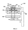
- FIG. 3 shows a section view of the embodiment of FIG. 1 in a fifth position.
- FIG. 4 shows a section view of the embodiment of FIG. 1 in a sixth position.
- FIG. 5A shows a perspective view of a closing block of a system according to one or more examples of embodiments of the present invention.
- FIG. 5B shows a perspective view of a closing block of a system according to one or more examples of embodiments of the present invention.
- FIG. 6 shows a perspective view of the closing block of the embodiment of FIG. 5A with capsule bodies visible.
- FIG. 7 shows a perspective view of a closing block of a system according to one or more examples of embodiments of the present invention.
- FIG. 8 shows a perspective view of a closing block of a system according to one or more examples of embodiments of the present invention.
- FIG. 9 shows a perspective view of the closing block of FIG. 8 with a hood and seal.
- FIG. 10 shows a perspective view of a system according to one or more examples of embodiments of the present invention.
- FIG. 11 shows a perspective view of a closing block of a system according to one or more examples of embodiments of the present invention.
- FIG. 12 is a top view of a specific embodiment of a capsule system.
- FIG. 13 is a perspective view of a specific embodiment of a capsule system.
- FIG. 14 is a cross section of a specific embodiment of a capsule system.
- Embodiments of the present disclosure comprise a system for coupling a cap and body of a capsule. Referring initially to FIGS. 1-4 , an exemplary embodiment of a system 100 for coupling a capsule cap and body is shown.
- cap plate 120 is configured to rotate so that other functions can be performed on the cap and body of the capsules.
- other stations may comprise aligning the caps and bodies and filling the capsule bodies and/or caps.
- the primary discussion will be focused on a system to couple the caps and bodies of the capsules. It is understood that embodiments of the present disclosure may be part of a larger system that includes other functions.
- system 100 comprises a closing block 110 , a cap plate 120 , a body plate 140 , and a backing block 150 .
- FIGS. 2A-4 show components of system 100 in various positions as the capsule body is coupled to the capsule cap.
- closing block 110 comprises an engagement surface 119 that is proximal to an engagement surface 129 of cap plate 120 .
- Closing block 110 further comprises a plurality of conduits 112 extending from engagement surface 119 into closing block 110 .
- conduits 112 extend through closing block 110 and are aligned with a plurality of conduits 114 in body plate 114 and a plurality of conduits 116 in cap plate 120 .
- a plurality of rods 113 are configured to extend into and through conduits 114 and 112 .
- system 100 also comprises an actuator 130 configured to move closing block 110 toward and away from cap plate 120 .
- actuator 130 is also configured to move rods 113 so that they may be directed into conduits 112 or retracted out of conduits 112 .
- rods 113 may be moved by an actuator that is separate from actuator 130 .
- a capsule body 118 may be placed in one or more conduits 112 and a capsule cap 117 may be placed in one or more conduits 116 .
- capsule bodies 118 may originally be placed in conduits 114 of body plate 140 (as shown in FIG. 2A ) and then be pushed into conduits 112 by rods 113 .
- actuator 130 moves closing block 110 towards cap plate 120 until engagement surface 119 contacts engagement surface 129 , as shown in FIG. 2D .
- actuator 130 moves rods 113 so that capsule bodies 118 are directed towards toward capsule caps 117 , as shown in FIG. 3 .
- actuator 130 continues moving rods 113 until capsule bodies 118 are coupled to capsule caps 117 , as shown in FIG. 4 .
- the movement of capsule bodies 118 in conduits 112 can cause air to be displaced from conduits 112 towards engagement surface 119 .
- the included figures are not drawn to scale and that the clearance between capsule bodies 118 and conduits 112 may be minimal in exemplary embodiments. It will often be desirable to minimize the clearance between capsule bodies 118 and conduits 112 so that capsule bodies 118 and capsule caps 117 are properly aligned when they are coupled. In such embodiments, there will be minimal leakage of air past capsule bodies 118 as they move within conduits 112 . When the clearance between capsule bodies 118 and conduits 112 is minimized, the majority of air contained in conduits 112 will be displaced toward engagement surface 119 as capsule bodies 118 move within conduits 112 .
- capsule bodies 118 are moved within conduit 112 so that capsule bodies 118 are proximal to engagement surface 119 before engagement surface 119 is engaged with engagement surface 129 . In certain embodiments, capsule bodies 118 are moved within conduit 112 so that capsule bodies 118 are essentially flush with engagement surface 119 before engagement surface 119 is engaged with engagement surface 129 . This can allow air within conduit 112 to be vented to atmosphere without the need for pressure relief cavities.
- closing block 110 may include a pressure-relief cavity 127 .
- pressure-relief cavity 127 is in fluid communication with conduits 112 and the surrounding atmosphere. Pressure-relief cavity 127 therefore allows air that is contained in conduit 112 to be vented to atmosphere as capsule body 118 is displaced towards engagement surface 119 . This will reduce the pressure buildup created in a capsule formed by the coupling of capsule body 118 and capsule cap 117 .
- pressure-relief cavity 127 is formed by drilling a hole from the side of closing block 110 towards conduit 112 until the drilled hole reaches conduit 112 .
- pressure-relief cavity 127 may extend from one side of closing block 110 to the opposite side of closing block 110 .
- a closing block and/or backing block may be coupled to a vacuum system, as described in more detail below.
- backing block 150 is located above cap plate 120 .
- backing block 150 includes supports 153 to restrict caps 117 from being moved axially when capsule bodies 118 are coupled to caps 117 .
- backing block 150 comprises a cavity 152 that is coupled to a vacuum system 151 .
- Cavity 152 is also in fluid communication with conduits 116 .
- Vacuum system 151 is configured to reduce the pressure in cavity 152 and conduits 116 .
- conduits 116 have pressure-relief cavities (including for example, axial channels or grooves running along the conduit) that allow air or other gasses trapped within conduit 116 to travel from engagement surface 129 towards cavity 152 .
- pressure-relief cavities including for example, axial channels or grooves running along the conduit
- cavity 152 may be vented to atmosphere rather than being coupled to vacuum system 151 .
- the use of vacuum system 151 may assist in lowering the pressure in cavity 152 and reducing an unwanted increase in pressure in conduits 112 and 116 .
- FIG. 5A a perspective view of one embodiment of closing block 110 illustrates conduits 112 and pressure-relief cavities 127 .
- four conduits 112 are shown, but it is understood that other embodiments may comprise less than or greater than four conduits 112 in closing block 110 .
- pressure-relief cavity 127 forms a conduit that extends from the outer edge of closing block 110 to conduit 112 .
- pressure-relief cavity 127 forms an aperture on the wall of conduit 112 at the location where pressure-relief cavity 127 intersects conduit 112 .
- pressure-relief cavities extend from one side of closing block 110 to the opposite side of closing block 110 and intersect conduits 112 .
- Conduits 112 comprise a circular cross-section in the portions where pressure-relief cavities 127 do not intersect conduits 112 .
- the circular cross-section provides alignment for capsule body 118 (which also comprises a circular cross-section in exemplary embodiments).
- conduits 112 do not comprise a circular cross-section. This allows capsule body 118 to move towards cap 117 without building up excessive pressure in a capsule formed by coupling body 118 and cap 117 .
- pressure-relief cavities 127 are proximal to engagement surface 119 . Such a configuration can allow pressure-relief cavities 127 to relieve pressure proximal to the location where capsule bodies 118 are coupled to capsule caps 116 . This can reduce the likelihood that unwanted pressure will form when capsules are created by coupling capsule bodies 118 and caps 116 . It is understood that other embodiments may comprise additional pressure-relief cavities, including for example, additional holes drilled from the side of closing block 110 and along the length of conduits 112 . A specific embodiment is shown in FIG. 5B , a series of slots milled into engagement surface 119 form pressure relief cavities 327 . Pressure relief cavities 327 function similar to the previously-described pressure relief cavities 127 .
- pressure relief cavities 327 are capable of venting conduits 112 while capsule bodies 118 are moving within conduits 112 until capsule bodies reach engagement surface 119 . It is understood that the exemplary embodiments shown in the figures are merely illustrative of a number of different configurations that are within the scope of the present invention.
- capsule bodies 118 are shown after they have been displaced along conduits 112 towards engagement surface 119 . Although not visible in conduits 112 (due to the presence of capsule bodies 118 proximal to engagement surface 119 ), pressure-relief cavities 127 are in fluid communication with conduits 112 .
- FIG. 7 another embodiment of closing block 110 comprises a different configuration of pressure-relief cavities.
- a plurality of pressure-relief cavities 227 are created by channels or grooves that run along the length of conduits 112 . While multiple pressure-relief cavities 227 are shown in each conduit 112 in this exemplary embodiment, it is understood that other exemplary embodiments may comprise a single pressure relief cavity in a conduit.
- Conduits 112 can be configured so that they still align capsule bodies 118 via the segment of the conduit disposed between the axial channels formed by pressure relief cavities 227 . However, as seen when looking down on conduits 112 (e.g., looking down on engagement surface 119 ), conduits 112 do not comprise a circular cross-section.
- capsule body 118 (which comprises a circular cross-section in exemplary embodiments) to move within conduit 112 without displacing air. Capsule body 118 can therefore move towards cap 117 without building up excessive pressure in a capsule formed by coupling body 118 and cap 117 .
- pressure-relief cavities 227 may also be used in conjunction with pressure-relief cavities 127 , as shown in FIG. 8 .
- relief cavities 227 can allow air to vent to atmosphere (e.g., via pressure-relief cavities 127 ) as capsule bodies 118 are moved within conduits 112 .
- the surface of closing block 110 that is opposite of engagement surface 119 e.g., the bottom surface when closing block 110 is positioned as shown in FIG. 7
- pressure-relief cavities 227 can allow air within conduit 112 to vent to atmosphere via the surface of closing block 110 that is opposite of engagement surface 119 .
- relief cavities 127 and/or 327 may also be configured to allow air within conduits 112 to be directed towards a vacuum system.
- conduits 116 in cap plate 120 may also comprise channels or grooves that can allow air to be directed from conduits 112 , through conduits 116 and into cavity 152 and vacuum system 151 .
- pressure-relief cavities 227 can be configured to allow air from conduits 112 to be directed to a vacuum system coupled to closing block 110 .
- closing block 110 may comprise a chamber 252 with an aperture 251 that can be coupled to a vacuum system (not shown).
- a plate (not visible in the figures) may be placed on the underneath side of block 110 to seal off conduits 212 from atmosphere and allow a sufficient vacuum to be established.
- closing block 150 comprises a series of channels 254 in engagement surface 119 that lead to chamber 252 .
- the channels 254 are in fluid communication with pressure-relief cavities 227 (not labeled in FIG. 9 for purposes of clarity) and therefore allow air from conduits 112 to be directed to chamber 252 .
- a seal 255 can extend around the perimeter of closing block 150 to help direct any air toward chamber 252 and a vacuum system (if used).
- Cover 253 may comprise a curved portion 263 configured to match the outer perimeter of cap plate 120 and assist in directing air from conduit 112 to chamber 252 . It is understood that cover 253 and seal 255 may be used with other embodiments incorporating a different configuration of pressure-relief cavities, including for example, those shown in FIGS. 5A , 5 B and 6 .
- channels 254 may be in fluid communication with chamber 252 and with conduits 112 that do not comprise pressure relief cavities 227 .
- the vacuum source coupled to chamber 252 will remove air displaced with conduit 112 as capsule body 118 is moved within conduit 112 . This vacuum actuation will reduce the pressure increase caused by the displacement of capsule body 118 towards capsule cap 117 .
- closing block 110 may be comprised of a porous material (including, for example, a sintered metal or a porous ceramic).
- the pressure relief cavities may comprise voids in the porous material rather than specific channels or conduits formed in closing block 110 .
- Such embodiments can allow for air at an elevated pressure to be diffused through the porous material as the capsule body 118 and cap 117 are brought together.
- the pressure relief cavities may not be visible to the naked eye, but can comprise multiple voids within closing block 110 that allow air to be directed from conduit 112 to an outer surface of closing block 110 and to the outside environment (or a vacuum source).
- a specific embodiment of the present disclosure comprises an F-40 capsule filling machine (available from Shionogi Qualicaps, Whitsett, N.C.) with certain components modified and/or replaced to provide the features described herein.
- a specific embodiment comprises a system 400 comprising a closing block 410 , a cap plate 420 , an actuator 430 , a body plate 440 and a backing block 450 .
- Components of the system shown in FIG. 10 are generally equivalent to previously-described components with similar reference numbers.
- component “4XX” is generally equivalent to component “1XX” in previously-described embodiments.
- capsules 418 are visible in conduits 414 of body plate 410 before they are directed to closing block 410 .
- closing block 410 comprises a seal 455 and a cover 453 configured to provide a sealed chamber when engagement surface 419 engages cap disk 420 . This can allow air expelled from conduits 412 (e.g., as capsule bodies 418 are directed upwards through conduits 412 ) to be directed to atmosphere or to a vacuum system.
- engagement surface 419 comprises the outer perimeter of backing block 450 rather than the entire upper surface.
- closing block 410 illustrates a plurality of conduits 412 in a 5 ⁇ 3 grid.
- pressure-relief cavities 427 are formed by drilling holes from one side of closing block 410 , through conduits 412 to the opposing side of closing block 410 . It is understood that in other embodiments, the number and location of the holes may vary from that shown in the embodiment of FIG. 11 . As shown in this embodiment, pressure-relief cavities 427 are formed near engagement surface 419 . This can allow pressure-relief cavities 427 to vent air from conduits 412 when capsule bodies 418 are proximal to capsule caps 417 and reduce the likelihood that excess pressure will be created in a capsule.
- Channels 454 leading to chamber 452 are also visible in the embodiment shown in FIG. 11 .
- a portion of conduits 112 extend above channels 454 and pressure-relief cavities 427 intersect conduits 112 in the portion that extends above channels.
- System 500 operates in a manner generally similar to previously-described embodiments, but includes different components and aspects of operation.
- system 500 comprises a plurality of body segments 501 and cap segments 502 .
- system 500 comprises a sealing member 505 that extends from cap segment 502 and is configured to engage body segment 501 .
- a body segment 501 comprises a plurality of extensions 503 that extend towards cap segment 502 .
- a capsule body will be flush with the upper surface of extension 503 (e.g., the surface that is closest to cap segment 502 ) when body segment 501 is moved towards cap segment 502 . Therefore, the capsule body will not translate within the conduit 512 that extends through body segment 501 .
- a capsule body may be slightly recessed from the upper surface of extension 503 when body segment 501 is moved towards cap segment 502 .
- a sealing member 505 extends down from cap segment 502 towards body segment 501 .
- Sealing member 505 can be coupled to a conduit 506 that is coupled to a vacuum source (not shown).
- the vacuum source can operate to pull a vacuum on sealing member 505 and reduce the pressure at the interface between body segment 501 and cap segment 502 .
- a partial cross section view of system 500 shows body segment 501 engaged with sealing member 505 .
- body segment 501 comprises a conduit 512 configured to align capsule body 118 with capsule cap 117 .
- Capsule segment 502 similarly comprises a conduit 516 configured to align capsule cap 117 with capsule body 118 .
- body segment 501 has been translated so that it is engaged with sealing member 505 , and capsule body 118 is in the process of being moved (via rod 513 ) towards capsule cap 117 .
- Capsule cap 117 can be held in place by a rod 514 during the engagement with capsule body 118 .
- a vacuum can be placed on sealing member 505 via conduit 506 and the vacuum source. This can reduce the potential for pressure to increase in the interface between capsule body 118 and capsule cap 117 and allow for a successful coupling of the components.
- joinder references are to be construed broadly and may include intermediate members between a connection of elements and relative movement between elements. As such, joinder references do not necessarily infer that two elements are directly connected and in fixed relation to each other.
- steps and operations are described in one possible order of operation, but those skilled in the art will recognize that steps and operations may be rearranged, replaced, or eliminated without necessarily departing from the spirit and scope of the present invention. It is intended that all matter contained in the above description or shown in the accompanying drawings shall be interpreted as illustrative only and not limiting. Changes in detail or structure may be made without departing from the spirit of the invention as defined in the appended claims.
Abstract
Description
- U.S. Pat. No. 3,554,412;
- U.S. Pat. No. 4,731,979;
- U.S. Pat. No. 5,321,932;
- U.S. Pat. No. 5,797,248;
- U.S. Pat. No. 6,286,567;
- U.S. Pat. No. 6,901,972.
Claims (23)
Priority Applications (5)
| Application Number | Priority Date | Filing Date | Title |
|---|---|---|---|
| US12/788,534 US8596025B2 (en) | 2009-06-01 | 2010-05-27 | Systems and methods for capsule pressure-relief |
| CA2764151A CA2764151C (en) | 2009-06-01 | 2010-05-28 | Systems and methods for capsule pressure-relief |
| EP10783849.2A EP2437716A4 (en) | 2009-06-01 | 2010-05-28 | Systems and methods for capsule pressure-relief |
| PCT/US2010/036530 WO2010141339A2 (en) | 2009-06-01 | 2010-05-28 | Systems and methods for capsule pressure-relief |
| US14/093,568 US9629781B2 (en) | 2009-06-01 | 2013-12-02 | Systems for capsule pressure-relief |
Applications Claiming Priority (2)
| Application Number | Priority Date | Filing Date | Title |
|---|---|---|---|
| US18277709P | 2009-06-01 | 2009-06-01 | |
| US12/788,534 US8596025B2 (en) | 2009-06-01 | 2010-05-27 | Systems and methods for capsule pressure-relief |
Related Child Applications (1)
| Application Number | Title | Priority Date | Filing Date |
|---|---|---|---|
| US14/093,568 Continuation US9629781B2 (en) | 2009-06-01 | 2013-12-02 | Systems for capsule pressure-relief |
Publications (2)
| Publication Number | Publication Date |
|---|---|
| US20110088355A1 US20110088355A1 (en) | 2011-04-21 |
| US8596025B2 true US8596025B2 (en) | 2013-12-03 |
Family
ID=43298416
Family Applications (2)
| Application Number | Title | Priority Date | Filing Date |
|---|---|---|---|
| US12/788,534 Active 2031-02-17 US8596025B2 (en) | 2009-06-01 | 2010-05-27 | Systems and methods for capsule pressure-relief |
| US14/093,568 Active 2032-01-01 US9629781B2 (en) | 2009-06-01 | 2013-12-02 | Systems for capsule pressure-relief |
Family Applications After (1)
| Application Number | Title | Priority Date | Filing Date |
|---|---|---|---|
| US14/093,568 Active 2032-01-01 US9629781B2 (en) | 2009-06-01 | 2013-12-02 | Systems for capsule pressure-relief |
Country Status (4)
| Country | Link |
|---|---|
| US (2) | US8596025B2 (en) |
| EP (1) | EP2437716A4 (en) |
| CA (1) | CA2764151C (en) |
| WO (1) | WO2010141339A2 (en) |
Cited By (5)
| Publication number | Priority date | Publication date | Assignee | Title |
|---|---|---|---|---|
| US20140137511A1 (en) * | 2009-06-01 | 2014-05-22 | Patheon International Ag | Systems and methods for capsule pressure-relief |
| US20200046611A1 (en) * | 2018-08-07 | 2020-02-13 | Harro Hoefliger Verpackungsmaschinen Gmbh | Capsule Closure Device for Closing Two-Piece Capsules |
| US10889394B2 (en) * | 2015-09-22 | 2021-01-12 | G.D Societa' Per Azioni | Machine to manufacture cartridges for electronic cigarettes and plant for the production of packages containing said cartridges for electronic cigarettes |
| US20210244617A1 (en) * | 2020-02-07 | 2021-08-12 | Harro Hoefliger Verpackungsmaschinen Gmbh | Capsule closure device for closing two-piece capsules |
| EP4151197A1 (en) * | 2021-09-17 | 2023-03-22 | Harro Höfliger Verpackungsmaschinen GmbH | Capsule filling machine for filling two-part capsules |
Families Citing this family (7)
| Publication number | Priority date | Publication date | Assignee | Title |
|---|---|---|---|---|
| DE102008013403A1 (en) * | 2008-03-10 | 2009-09-17 | Robert Bosch Gmbh | Capsule carrier arrangement for filling and closing machines |
| MX363959B (en) | 2011-10-06 | 2019-04-09 | Combocap Inc | A method and apparatus for manufacturing a capsule. |
| US9456987B2 (en) | 2013-04-03 | 2016-10-04 | Binutra, Inc. | Capsule with internal diaphragm |
| ES2924175T3 (en) * | 2018-03-28 | 2022-10-05 | Hoefliger Harro Verpackung | Capsule sleeve for snap-on capsules and sleeve system |
| EP3620150B1 (en) * | 2018-09-06 | 2021-02-17 | Scitech Centre | A tamping assembly |
| CN109620730B (en) * | 2018-12-22 | 2021-08-17 | 杭州伽南企业管理有限公司 | Household small-sized medicinal powder filling machine for medicinal capsules |
| US20210137791A1 (en) * | 2019-11-11 | 2021-05-13 | Joey R. Gonzales | Capsule filler |
Citations (12)
| Publication number | Priority date | Publication date | Assignee | Title |
|---|---|---|---|---|
| US2108906A (en) * | 1937-07-21 | 1938-02-22 | Stephen J Speckhart | Capsule filling machine |
| US3554412A (en) | 1967-03-13 | 1971-01-12 | Sankyo Co | Capsule charging system |
| US4403461A (en) * | 1980-02-29 | 1983-09-13 | Automatisme Et Technique | Device for sealing hard gelatin capsules and for packing a liquid product dose in the thus sealed capsule |
| US4731979A (en) | 1985-02-27 | 1988-03-22 | Nippon Elanco Kabushiki Kaisha | Capsule filling apparatus |
| US4940499A (en) | 1989-05-23 | 1990-07-10 | Warner-Lambert Company | Method and apparatus for sealing capsules containing medicaments |
| US5321932A (en) | 1992-02-26 | 1994-06-21 | Professional Compounding Centers Of America, Inc. | Capsule handling system |
| US5797248A (en) | 1996-05-07 | 1998-08-25 | Willem Wassenaar | Manual capsule filling device |
| US6286567B1 (en) | 1997-09-30 | 2001-09-11 | Robert Bosch Gmbh | Apparatus for volumetric metering of small quantities of product and dispensing them into containers |
| KR20050028012A (en) | 2002-07-05 | 2005-03-21 | 시오노기쿠오리카프스 가부시키가이샤 | Capsule-filling and-sealing apparatus |
| US6901972B1 (en) | 2003-12-03 | 2005-06-07 | John Nelson | Capsule filling device and method of operation |
| WO2008015519A1 (en) | 2006-08-04 | 2008-02-07 | Pfizer Products Inc. | Method and apparatus for sealing capsules |
| US20080141621A1 (en) | 2004-02-27 | 2008-06-19 | Caterina Funaro | Method and Related Capsule Filling Machine For Producing Sealed Capsules |
Family Cites Families (8)
| Publication number | Priority date | Publication date | Assignee | Title |
|---|---|---|---|---|
| US2831301A (en) * | 1956-03-06 | 1958-04-22 | Smith Kline French Lab | Method and apparatus for assembling capsules |
| CH516435A (en) * | 1966-11-21 | 1971-12-15 | Sankyo Co | Device for filling containers in the form of capsules, tubes or bottles with pourable material |
| IT1203137B (en) * | 1978-11-09 | 1989-02-15 | Facchini Libero | CONTINUOUS MOVING OPERATING MACHINE FOR THE PACKAGING OF PULVERULENT OR GRANULAR PRODUCTS |
| IT1266251B1 (en) * | 1993-02-16 | 1996-12-27 | Ima Spa | DEVICE FOR THE ORIENTATION OF THE BOTTOM AND THE LID OF HARD JELLY CAPSULES AND FOR THE FEEDING OF THESE WORKS |
| IT1316684B1 (en) * | 1999-03-13 | 2003-04-24 | Bosch Gmbh Robert | SUPPORT OF CAPSULE PARTS IN A TWO-PART CAPSULE LOADING AND DECLARING MACHINE |
| JP4059466B2 (en) * | 2000-06-19 | 2008-03-12 | 三菱瓦斯化学株式会社 | Process for producing polyphenylene ether |
| GB0027954D0 (en) * | 2000-11-16 | 2001-01-03 | Mw Encap Ltd | Liquid filled capsules |
| US8596025B2 (en) * | 2009-06-01 | 2013-12-03 | Patheon International Ag | Systems and methods for capsule pressure-relief |
-
2010
- 2010-05-27 US US12/788,534 patent/US8596025B2/en active Active
- 2010-05-28 WO PCT/US2010/036530 patent/WO2010141339A2/en active Application Filing
- 2010-05-28 CA CA2764151A patent/CA2764151C/en not_active Expired - Fee Related
- 2010-05-28 EP EP10783849.2A patent/EP2437716A4/en not_active Withdrawn
-
2013
- 2013-12-02 US US14/093,568 patent/US9629781B2/en active Active
Patent Citations (14)
| Publication number | Priority date | Publication date | Assignee | Title |
|---|---|---|---|---|
| US2108906A (en) * | 1937-07-21 | 1938-02-22 | Stephen J Speckhart | Capsule filling machine |
| US3554412A (en) | 1967-03-13 | 1971-01-12 | Sankyo Co | Capsule charging system |
| US4403461A (en) * | 1980-02-29 | 1983-09-13 | Automatisme Et Technique | Device for sealing hard gelatin capsules and for packing a liquid product dose in the thus sealed capsule |
| US4731979A (en) | 1985-02-27 | 1988-03-22 | Nippon Elanco Kabushiki Kaisha | Capsule filling apparatus |
| US4940499A (en) | 1989-05-23 | 1990-07-10 | Warner-Lambert Company | Method and apparatus for sealing capsules containing medicaments |
| US5321932A (en) | 1992-02-26 | 1994-06-21 | Professional Compounding Centers Of America, Inc. | Capsule handling system |
| US5797248A (en) | 1996-05-07 | 1998-08-25 | Willem Wassenaar | Manual capsule filling device |
| US6286567B1 (en) | 1997-09-30 | 2001-09-11 | Robert Bosch Gmbh | Apparatus for volumetric metering of small quantities of product and dispensing them into containers |
| KR20050028012A (en) | 2002-07-05 | 2005-03-21 | 시오노기쿠오리카프스 가부시키가이샤 | Capsule-filling and-sealing apparatus |
| US20050217207A1 (en) * | 2002-07-05 | 2005-10-06 | Hirokazu Konishi | Capsule-filling and sealing apparatus |
| US6901972B1 (en) | 2003-12-03 | 2005-06-07 | John Nelson | Capsule filling device and method of operation |
| US20080141621A1 (en) | 2004-02-27 | 2008-06-19 | Caterina Funaro | Method and Related Capsule Filling Machine For Producing Sealed Capsules |
| WO2008015519A1 (en) | 2006-08-04 | 2008-02-07 | Pfizer Products Inc. | Method and apparatus for sealing capsules |
| US20100018167A1 (en) * | 2006-08-04 | 2010-01-28 | Mccutcheon Gabriel M | Method and Apparatus for Sealing Capsules |
Non-Patent Citations (1)
| Title |
|---|
| International Search Report PCT/US2010/036530 dated Feb. 9, 2011 (3 pgs.). |
Cited By (7)
| Publication number | Priority date | Publication date | Assignee | Title |
|---|---|---|---|---|
| US20140137511A1 (en) * | 2009-06-01 | 2014-05-22 | Patheon International Ag | Systems and methods for capsule pressure-relief |
| US9629781B2 (en) * | 2009-06-01 | 2017-04-25 | Patheon Pharmaceuticals Inc. | Systems for capsule pressure-relief |
| US10889394B2 (en) * | 2015-09-22 | 2021-01-12 | G.D Societa' Per Azioni | Machine to manufacture cartridges for electronic cigarettes and plant for the production of packages containing said cartridges for electronic cigarettes |
| US20200046611A1 (en) * | 2018-08-07 | 2020-02-13 | Harro Hoefliger Verpackungsmaschinen Gmbh | Capsule Closure Device for Closing Two-Piece Capsules |
| US11857503B2 (en) * | 2018-08-07 | 2024-01-02 | Harro Hoefliger Verpackungsmaschinen Gmbh | Capsule closure device for closing two-piece capsules |
| US20210244617A1 (en) * | 2020-02-07 | 2021-08-12 | Harro Hoefliger Verpackungsmaschinen Gmbh | Capsule closure device for closing two-piece capsules |
| EP4151197A1 (en) * | 2021-09-17 | 2023-03-22 | Harro Höfliger Verpackungsmaschinen GmbH | Capsule filling machine for filling two-part capsules |
Also Published As
| Publication number | Publication date |
|---|---|
| EP2437716A2 (en) | 2012-04-11 |
| WO2010141339A2 (en) | 2010-12-09 |
| US20110088355A1 (en) | 2011-04-21 |
| CA2764151C (en) | 2017-08-29 |
| CA2764151A1 (en) | 2010-12-09 |
| US9629781B2 (en) | 2017-04-25 |
| US20140137511A1 (en) | 2014-05-22 |
| EP2437716A4 (en) | 2014-09-17 |
| WO2010141339A3 (en) | 2011-04-14 |
Similar Documents
| Publication | Publication Date | Title |
|---|---|---|
| US8596025B2 (en) | Systems and methods for capsule pressure-relief | |
| CA2862465C (en) | Needleless valve system fluid control | |
| AU2002313463B2 (en) | Pharmaceutical syringe piston and method and device therefor | |
| EP3349713B1 (en) | Septum that decontaminates by interaction with penetrating element | |
| US20170081056A1 (en) | Method of sealing a container comprising at least one plug, particularly a carpule, insertion means and associated sealing line | |
| US8715722B2 (en) | Capsule with air-vents | |
| JP2006506144A5 (en) | ||
| EP1787948A3 (en) | Method for flip-chip packaging MEMS | |
| ITMO20080085A1 (en) | APPARATUS FOR FORMING ASEPTIC CONTAINERS | |
| CN103921966A (en) | Apparatus and method for filling flangeless containers | |
| CN103987357A (en) | A method and apparatus for manufacturing a capsule | |
| EP2933041B1 (en) | A method of and a device for the compaction of a powder into a cutting insert green body | |
| JPS6181975A (en) | Feeder for pasty material | |
| ITMI980360A1 (en) | EVACUATION AND CLOSING DEVICE FOR SMALL CONTAINERS PRESENTING A CLOSING CAP | |
| JP7032562B2 (en) | Fixed-quantity discharge device for liquid containers | |
| KR20160107730A (en) | Battery Cell Degassing And Sealing Machine | |
| US20060168916A1 (en) | Method and apparatus to insert stoppers into prefilled syringes | |
| JP2013001450A (en) | Method of manufacturing capsule product | |
| AU2019100522A4 (en) | Vial stopper | |
| CN105151381A (en) | Vacuumizing nitrogen feeding tamponade device and production line | |
| CN104786237A (en) | Glove device on isolator and glove replacing method | |
| KR102056136B1 (en) | Charging device | |
| CN204700896U (en) | Gloves apparatus on a kind of isolator | |
| CN110861330B (en) | Process method and manufacturing equipment for liquid packaging product | |
| WO2015190715A1 (en) | Fixed nozzle type pumping cosmetic container |
Legal Events
| Date | Code | Title | Description |
|---|---|---|---|
| AS | Assignment |
Owner name: PATHEON INTERNATIONA AG, SWITZERLAND Free format text: ASSIGNMENT OF ASSIGNORS INTEREST;ASSIGNOR:FULPER, LESTER DAVID;REEL/FRAME:027317/0566 Effective date: 20101029 |
|
| AS | Assignment |
Owner name: MORGAN STANLEY SENIOR FUNDING, INC., AS COLLATERAL Free format text: SECURITY AGREEMENT;ASSIGNOR:PATHEON INTERNATIONAL AG;REEL/FRAME:029482/0045 Effective date: 20121214 |
|
| STCF | Information on status: patent grant |
Free format text: PATENTED CASE |
|
| AS | Assignment |
Owner name: PATHEON PHARMACEUTICALS INC., OHIO Free format text: ASSIGNMENT OF ASSIGNORS INTEREST;ASSIGNOR:PATHEON INTERNATIONAL AG;REEL/FRAME:032559/0311 Effective date: 20140328 |
|
| AS | Assignment |
Owner name: PATHEON INTERNATIONAL AG, SWITZERLAND Free format text: TERMINATION AND RELEASE OF SECURITY INTEREST IN PATENT RIGHTS;ASSIGNOR:MORGAN STANLEY SENIOR FUNDING, INC.;REEL/FRAME:032745/0532 Effective date: 20140311 |
|
| FEPP | Fee payment procedure |
Free format text: PAT HOLDER NO LONGER CLAIMS SMALL ENTITY STATUS, ENTITY STATUS SET TO UNDISCOUNTED (ORIGINAL EVENT CODE: STOL); ENTITY STATUS OF PATENT OWNER: LARGE ENTITY |
|
| FPAY | Fee payment |
Year of fee payment: 4 |
|
| MAFP | Maintenance fee payment |
Free format text: PAYMENT OF MAINTENANCE FEE, 8TH YEAR, LARGE ENTITY (ORIGINAL EVENT CODE: M1552); ENTITY STATUS OF PATENT OWNER: LARGE ENTITY Year of fee payment: 8 |