EP3545846B1 - Réglage d'un collimateur d'une source de rayons x - Google Patents
Réglage d'un collimateur d'une source de rayons x Download PDFInfo
- Publication number
- EP3545846B1 EP3545846B1 EP18163993.1A EP18163993A EP3545846B1 EP 3545846 B1 EP3545846 B1 EP 3545846B1 EP 18163993 A EP18163993 A EP 18163993A EP 3545846 B1 EP3545846 B1 EP 3545846B1
- Authority
- EP
- European Patent Office
- Prior art keywords
- ray
- collimator
- ray source
- ray detector
- detector
- Prior art date
- Legal status (The legal status is an assumption and is not a legal conclusion. Google has not performed a legal analysis and makes no representation as to the accuracy of the status listed.)
- Active
Links
- 238000012545 processing Methods 0.000 claims description 42
- 238000000034 method Methods 0.000 claims description 27
- 238000004590 computer program Methods 0.000 claims description 15
- 238000003384 imaging method Methods 0.000 description 62
- 230000005855 radiation Effects 0.000 description 22
- 238000012546 transfer Methods 0.000 description 4
- 230000008878 coupling Effects 0.000 description 3
- 238000010168 coupling process Methods 0.000 description 3
- 238000005859 coupling reaction Methods 0.000 description 3
- 230000006870 function Effects 0.000 description 3
- 230000003287 optical effect Effects 0.000 description 3
- 238000004891 communication Methods 0.000 description 1
- 238000012937 correction Methods 0.000 description 1
- 230000003247 decreasing effect Effects 0.000 description 1
- 230000001419 dependent effect Effects 0.000 description 1
- 238000010586 diagram Methods 0.000 description 1
- 238000002955 isolation Methods 0.000 description 1
- 230000004044 response Effects 0.000 description 1
Images

Classifications
-
- A—HUMAN NECESSITIES
- A61—MEDICAL OR VETERINARY SCIENCE; HYGIENE
- A61B—DIAGNOSIS; SURGERY; IDENTIFICATION
- A61B6/00—Apparatus or devices for radiation diagnosis; Apparatus or devices for radiation diagnosis combined with radiation therapy equipment
- A61B6/54—Control of apparatus or devices for radiation diagnosis
- A61B6/545—Control of apparatus or devices for radiation diagnosis involving automatic set-up of acquisition parameters
-
- A—HUMAN NECESSITIES
- A61—MEDICAL OR VETERINARY SCIENCE; HYGIENE
- A61B—DIAGNOSIS; SURGERY; IDENTIFICATION
- A61B6/00—Apparatus or devices for radiation diagnosis; Apparatus or devices for radiation diagnosis combined with radiation therapy equipment
- A61B6/58—Testing, adjusting or calibrating thereof
- A61B6/587—Alignment of source unit to detector unit
-
- A—HUMAN NECESSITIES
- A61—MEDICAL OR VETERINARY SCIENCE; HYGIENE
- A61B—DIAGNOSIS; SURGERY; IDENTIFICATION
- A61B6/00—Apparatus or devices for radiation diagnosis; Apparatus or devices for radiation diagnosis combined with radiation therapy equipment
- A61B6/06—Diaphragms
-
- A—HUMAN NECESSITIES
- A61—MEDICAL OR VETERINARY SCIENCE; HYGIENE
- A61B—DIAGNOSIS; SURGERY; IDENTIFICATION
- A61B6/00—Apparatus or devices for radiation diagnosis; Apparatus or devices for radiation diagnosis combined with radiation therapy equipment
- A61B6/08—Auxiliary means for directing the radiation beam to a particular spot, e.g. using light beams
-
- A—HUMAN NECESSITIES
- A61—MEDICAL OR VETERINARY SCIENCE; HYGIENE
- A61B—DIAGNOSIS; SURGERY; IDENTIFICATION
- A61B6/00—Apparatus or devices for radiation diagnosis; Apparatus or devices for radiation diagnosis combined with radiation therapy equipment
- A61B6/44—Constructional features of apparatus for radiation diagnosis
- A61B6/4405—Constructional features of apparatus for radiation diagnosis the apparatus being movable or portable, e.g. handheld or mounted on a trolley
-
- A—HUMAN NECESSITIES
- A61—MEDICAL OR VETERINARY SCIENCE; HYGIENE
- A61B—DIAGNOSIS; SURGERY; IDENTIFICATION
- A61B6/00—Apparatus or devices for radiation diagnosis; Apparatus or devices for radiation diagnosis combined with radiation therapy equipment
- A61B6/44—Constructional features of apparatus for radiation diagnosis
- A61B6/4411—Constructional features of apparatus for radiation diagnosis the apparatus being modular
-
- A—HUMAN NECESSITIES
- A61—MEDICAL OR VETERINARY SCIENCE; HYGIENE
- A61B—DIAGNOSIS; SURGERY; IDENTIFICATION
- A61B6/00—Apparatus or devices for radiation diagnosis; Apparatus or devices for radiation diagnosis combined with radiation therapy equipment
- A61B6/44—Constructional features of apparatus for radiation diagnosis
- A61B6/4429—Constructional features of apparatus for radiation diagnosis related to the mounting of source units and detector units
- A61B6/4452—Constructional features of apparatus for radiation diagnosis related to the mounting of source units and detector units the source unit and the detector unit being able to move relative to each other
-
- A—HUMAN NECESSITIES
- A61—MEDICAL OR VETERINARY SCIENCE; HYGIENE
- A61B—DIAGNOSIS; SURGERY; IDENTIFICATION
- A61B6/00—Apparatus or devices for radiation diagnosis; Apparatus or devices for radiation diagnosis combined with radiation therapy equipment
- A61B6/46—Arrangements for interfacing with the operator or the patient
-
- A—HUMAN NECESSITIES
- A61—MEDICAL OR VETERINARY SCIENCE; HYGIENE
- A61B—DIAGNOSIS; SURGERY; IDENTIFICATION
- A61B6/00—Apparatus or devices for radiation diagnosis; Apparatus or devices for radiation diagnosis combined with radiation therapy equipment
- A61B6/58—Testing, adjusting or calibrating thereof
- A61B6/588—Setting distance between source unit and detector unit
-
- A—HUMAN NECESSITIES
- A61—MEDICAL OR VETERINARY SCIENCE; HYGIENE
- A61B—DIAGNOSIS; SURGERY; IDENTIFICATION
- A61B6/00—Apparatus or devices for radiation diagnosis; Apparatus or devices for radiation diagnosis combined with radiation therapy equipment
- A61B6/54—Control of apparatus or devices for radiation diagnosis
- A61B6/547—Control of apparatus or devices for radiation diagnosis involving tracking of position of the device or parts of the device
-
- G—PHYSICS
- G21—NUCLEAR PHYSICS; NUCLEAR ENGINEERING
- G21K—TECHNIQUES FOR HANDLING PARTICLES OR IONISING RADIATION NOT OTHERWISE PROVIDED FOR; IRRADIATION DEVICES; GAMMA RAY OR X-RAY MICROSCOPES
- G21K1/00—Arrangements for handling particles or ionising radiation, e.g. focusing or moderating
- G21K1/02—Arrangements for handling particles or ionising radiation, e.g. focusing or moderating using diaphragms, collimators
- G21K1/04—Arrangements for handling particles or ionising radiation, e.g. focusing or moderating using diaphragms, collimators using variable diaphragms, shutters, choppers
Definitions
- the present invention relates to a method for adjusting a collimator of an X-ray source and to a corresponding X-ray device. Furthermore, a corresponding computer program product and a computer readable media are provided.
- An X-ray imaging device may comprise a fixed X-ray detector such that the position and size of the X-ray detector as well as the distance between the X-ray radiation source and the X-ray detector are well defined within the X-ray imaging device.
- the X-ray imaging device may be configured such that the size of a light field irradiated by the X-ray source matches to an active field of the X-ray detector.
- X-ray imaging devices may also utilise mobile X-ray detectors to allow free exposures.
- the mobile X-ray detector may be arranged as required with respect to an examination object and the radiation X-ray source may be moved freely to focus on a region of interest of the examination object, for example a body part of a patient to be examined.
- EP 2 767 236 A1 discloses an X-ray collimator size and position adjustment based on pre-shot.
- An apparatus comprises a field-of-view corrector configured to receive a scout image acquired by an imager with a tentative collimator setting in the pre-shot imaging phase where the imager operates with a low dosage radiation cone causing the detector to register the scout image.
- the field-of-view corrector uses the scout image to establish field-of-view correction information for a subsequent imaging phase where the imager is to operate with a high dosage radiation cone.
- US 2017/0055925 A1 relates to an X-ray imaging apparatus using a camera image to set various types of parameters related to X-ray imaging including an X-ray irradiation region and automatically controlling X-ray imaging.
- a control unit may extract a boundary of an X-ray detector or a mounting unit on which the X-ray detector is mounted shown in the camera image to extract a detector boundary line, and may determine whether the X-ray detector and the X-ray source are aligned with each other based on an X-ray irradiation window displayed at the calculated position of the X-ray irradiation region or the calculated position of the light irradiation region and the extracted detector boundary line.
- a control unit may calculate a moving distance or a moving direction of the X-ray source or the X-ray detector for aligning the X-ray source and the X-ray detector with each other.
- US 2012/015515 A1 relates to a method for adjusting a collimator radiation field in an X-ray imaging system.
- the method may include aligning the center of a collimator with a detector; acquiring at least one relative distance parameter of the collimator; acquiring at least one radiation field parameter; calculating at least one moving parameters of each blade of the collimator according to the at least one radiation field parameter and relative distance parameter; and independently moving each blade according to the at least one moving parameter to obtain a radiation field with a desired size and location.
- US 2016/0220223 A1 relates to an X-ray apparatus including an X-ray source configured to radiate X-rays, a collimator configured to adjust a radiation field of the X-rays and rotate on an optical axis direction of the X-rays, a ring-shaped first rotation transfer unit centered on an optical axis of the X-rays in the X-ray source, a second rotation transfer unit interlocked with the ring-shaped first rotation transfer unit and configured to rotate as the collimator rotates, a rotation sensor configured to sense an amount of rotation of the second rotation transfer unit, and a detector comprising a receiving surface on which the X-rays radiated from the collimator are incident.
- the X-ray apparatus may obtain information about the position of the detector including the receiving surface on which X-rays are incident. For example, when the detector of the X-ray apparatus is a fixed-type detector, the information about the position of the detector may be stored in a memory. When the detector of the X-ray apparatus is a mobile detector, the controller of the X-ray apparatus may obtain information about the position of the detector as a user inputs the information about the position of the detector by using the input unit.
- an area irradiated by the X-ray source may be larger or may extend beyond an active field of the mobile X-ray detector. This may lead to an increased X-ray dose for the patient.
- An operator of the X-ray imaging device may align the X-ray source and may adjust a collimator of the X-ray source such that the collimated field is restricted to the active area of the X-ray detector.
- this demand may be difficult to fulfil and may require several iterations of manual adjustment, which may be time-consuming.
- a method for adjusting a collimator of an X-ray source is provided.
- an arrangement of an X-ray detector with respect to the X-ray source is detected.
- the position and/or orientation of the X-ray source is controlled with a processing device by generating control signals for at least one actuator connected to the X-ray source.
- Detecting the arrangement comprises capturing an image comprising the X-ray detector and automatically computing, based on the captured image, which is showing the x-ray detector, and based on the control of the at least one actuator, a distance between the X-ray detector and the X-ray source, an orientation of the X-ray detector with respect to the X-ray source, and a size of an active field of the X-ray detector.
- an adjustment for the collimator is automatically determined.
- the collimator is automatically adjusted.
- a camera for example a digital camera, in particular a digital 3-D camera, may be used to detect the arrangement of the X-ray detector.
- the X-ray detector may comprise a mobile X-ray detector allowing free exposure arrangement of the X-ray detector.
- a position of the camera with respect to the X-ray source may be fixed.
- the camera may additionally detect the position and orientation of the X-ray source such that the arrangement of the X-ray detector with respect to the X-ray source may be determined.
- an image showing the X-ray detector and the X-ray source may be captured and based on the captured image, a distance between the X-ray detector and the X-ray source, an orientation of the X-ray detector with respect to the X-ray source, and/or a size of an active field of the X-ray detector may be automatically determined, for example by a processing device which performs an image processing.
- parameters like X-ray detector position and orientation, distance between the X-ray detector and the X-ray source, a size and an orientation of the collimator may be determined in a three-dimensional coordinate system or relative to the camera.
- the active area of the mobile X-ray detector and the area irradiated by the collimator may be compared and the setup may be changed automatically, in particular adjusting the collimator.
- the maximum opening of the collimator may be limited to the borders of the mobile X-ray detector such that an X-ray dose irradiated on the patient may be decreased.
- automatically adjusting the collimator may comprise automatically adjusting a height or automatically adjusting a width of a light field of the collimator. Further, a rotation of the light field of the collimator may automatically be adjusted. This may limit the maximum opening of the collimator to the borders of the mobile X-ray detector. Further, free arrangement of the mobile X-ray detector may be supported, for example by rotating the light field of the collimator. Further, when the distance between the X-ray source and the mobile X-ray detector is changed, the collimator size may be adapted so that the collimation of the light field remains the same. Adjusting the width, height and/or rotation of the light field of the collimator may be accomplished by adjusting corresponding blades which may be driven by actuators controlled by a processing device.
- the arrangement of the X-ray source is adjustable. For detecting the arrangement of the X-ray detector with respect to the X-ray source, the position of the X-ray detector may be detected and an adjustment for the X-ray source may be automatically determined based on the detected position of the X-ray detector. A position of the X-ray source is automatically adjusted based on this determined adjustment for the X-ray source. The position of the X-ray detector as well as the position of the X-ray source may be determined based on an image captured by a camera, in particular a 3-D camera.
- a processing device may determine that this setup has to be changed. If the position and orientation of the X-ray detector have to be changed, the X-ray source may be moved to a position where an area irradiated by the X-ray source (light field) covers the active area of the X-ray detector. Next, the collimator may be adjusted such that the area irradiated by the X-ray source (light field) does not extend beyond the active area of the X-ray detector.
- a warning indicating that an optimal adjustment of the collimator cannot be achieved with the detected arrangement of the X-ray detector with respect to the X-ray source is output to an operator.
- the operator may then consider to rearrange the X-ray detector in combination with the object to be examined, and the above-described method may be repeated for automatically adjusting the collimator.
- an X-ray device comprises an X-ray source comprising a collimator, at least one actuator connected to the X-ray source, a capturing device configured to detect an arrangement of an X-ray detector with respect to the X-ray source, and a processing device.
- the capturing device may comprise for example a camera, in particular a 3-D digital camera. Detecting the arrangement comprises capturing an image comprising the X-ray detector.
- the processing device may comprise for example a digital processing device like a controller or a central processing unit (CPU) including memory and input and output interfaces for receiving information from for example the capturing device, a graphical user interface, and for providing information to actuators for adjusting the collimator.
- CPU central processing unit
- the processing device is configured to compute, based on the captured image, which is showing the x-ray detector, and based on the control of the at least one actuator, a distance between the X-ray detector and the X-ray source, an orientation of the X-ray detector with respect to the X-ray source, and a size of an active field of the X-ray detector, and to determine an adjustment for the collimator based on the detected position of the X-ray detector with respect to the X-ray source, and to adjust the collimator based on the determined adjustment for the collimator.
- the X-ray device may be configured to perform the above-described method.
- a further aspect of the present invention relates to a computer program product comprising a computer program.
- the computer program is loadable into a memory of a processing device of an X-ray device.
- the computer program includes program code sections to cause the processing device to execute the above-described method when the computer program is executed in the processing device.
- the computer program product may comprise other elements apart from the computer program. These other elements may be hardware, for example a memory device, on which the computer program is stored, a hardware key for using the computer program and the like, and/or software, for example a documentation or a software key for using the computer program.
- a computer readable media which includes computer executable instructions for performing the above-described method.
- the computer readable media may comprise for example a DVD, a magnetic tape, a hard disk or an USB stick, on which electronically readable control information, in particular software, is stored.
- the above-described method may be performed by the processing device.
- Fig. 1 shows schematically an X-ray imaging device 100.
- the X-ray imaging device 100 comprises an X-ray source 101 comprising a radiation source 102 , for example an X-ray tube, configured to emit an X-ray beam through a collimator 104.
- the collimator 104 is arranged to collimate the X-ray beam.
- the collimator 104 may be configured to restrict a spatial extent of the X-ray beam in one or more directions perpendicular to a direction of propagation of the beam.
- the X-ray beam passing through the collimator 104 is further passing through an collimator adjustment system 103 of the collimator 104.
- the collimator adjustment system 103 may comprise movable blades for adjusting a light field which is irradiated by the X-ray beam passing through the collimator 104.
- the X-ray source 101 comprises furthermore an actuator 105 which may be coupled to the collimator adjustment system 103 for moving the blades based on control information provided to the actuator 105.
- the X-ray source 101 may comprise a further actuator 107 for adjusting a position and an orientation of the X-ray source 101. Furthermore, the X-ray source 101 may comprise further components, for example a further actuator for moving the radiation source 102 with respect to the collimator 104.
- An X-ray beam 130 generated by the X-ray source 101 may be directed to an object 106 to be imaged.
- the object 106 may be located on or near an imaging platform 108.
- the imaging platform 108 may comprise or constitute an X-ray detector arranged to detect X-ray radiation emitted from the radiation source 102.
- the imaging platform 108 may be arranged to receive a cassette containing a radiographic or photographic film reactive to the radiation emitted from the radiation source 102.
- the imaging platform 108 may comprise an electronic flat panel X-ray detector.
- the imaging platform 108 may have an active area 109 which is responsive to the incoming X-ray radiation, whereas a remaining part of the surface of the imaging platform 108, for example a frame surrounding the active area 109, may not be responsive to the incoming X-ray radiation.
- the X-ray imaging device 100 may comprise a processing device 110 for controlling the radiation source 102 and the actuators 105, 107.
- the processing device 110 controls a position and/or an orientation of the X-ray source 101 to control a position from which radiation is emitted from the radiation source 102 and may control one or more settings of the collimator 104.
- the processing device 110 may be configured to generate control signals for controlling drive motors or other electromechanical drives of the actuators 105, 107 connected to the X-ray source 101 and the collimator 104 to control the position, orientation, and/or extent of the emitted X-ray beam 130.
- the processing device 110 may be implemented using hardware and/or software.
- the processing device 110 may comprise a processor 112 programmed to perform the functions of the processing device 110.
- the control device 110 may further include a memory 114 arranged to store data, for example program code executable by the processor 112 to perform the functions of the processing device 110.
- the program code may be loaded into the memory 114 from a computer readable media, for example a DVD 118, an USB stick or via a data communication network.
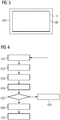
- the program code may in particular be configured to perform a method described herein with reference to Fig. 4 .
- the imaging device 100 comprises a capturing device 116 configured to detect an arrangement of the imaging platform 108 with respect to the X-ray source 101.
- the capturing device 116 may comprise for example a camera, for example an optical digital camera, in particular a 3-D camera.
- the camera may be configured to provide one or more color channels or may be configured to provide a greyscale image.
- the 3-D camera may be configured to provide one or more color or greyscale channels and one or more depth channels.
- the imaging device 100 may comprise one or more (not shown) interfaces for receiving a connection to a camera not permanently connected to the imaging device 100.
- the capturing device may be mechanically connected to the X-ray source 101 so that the capturing device moves together with the X-ray source 101. Accordingly, images generated by the capturing device will include an area that will be irradiated by the radiation source 102 wherever the X-ray source 101 is located.
- the capturing device 116 may be arranged spaced apart from the X-ray source 101 and the imaging platform 108, but such that an image captured by the capturing device 116 shows at least the imaging platform 108 and optionally also the X-ray source 101.
- a relative arrangement between the capturing device 116 and the X-ray source 101 is also known to the processing device 110 based on a control of the actuator 107. Additionally the image captured by the capturing device 116 may show the arrangement of the imaging platform 108 in relation to the X-ray source 101.
- the imaging platform 108 is movable and may be freely arranged as required and appropriate for taking X-ray images of an object to be examined, for example of a body part like an arm or leg of a patient.
- the active area 109 of the imaging platform 108 may not match to an area irradiated by the X-ray beam 130.
- the area irradiated by the X-ray beam 130 will be called in the following light field of the X-ray source 101.
- the light field of the X-ray source 101 may be defined by its outline or contour, for example by a width, a height and an orientation.
- the outline of the light field may be modified by rearranging the X-ray source 101, for example controlled by the processing device 110 using the actuator 107.
- a matching of the light field of the X-ray beam 130 to the active area 109 of the imaging platform 108 may not be possible.
- the width-to-height-ratio of the active area 109 and the light field of the X-ray beam 130 may not be matching.
- Fig. 2 shows an example of an active area 109 of the imaging platform 108 which does not match to the light field 131 of the X-ray beam 130.
- Steps 401 to 403 illustrate an example of detecting an arrangement of the imaging platform (X-ray detector) 108 with respect to the X-ray source 101.
- an image is captured with the capturing device 116.
- the image comprises at least an image of the imaging platform 108, in particular the active area 109 which is sensitive to the X-ray beam 130.
- the X-ray source 101 is movable under control of the actuator 107.
- a position and orientation of the X-ray source 101 is configurable and controllable via the actuator 107 by the processing device 110. If the position of the capturing device 116 and the current position of the X-ray source 101 is known to the processing device 110, the arrangement of the imaging platform 108 with respect to the X-ray source 101 may be determined based on the image from the capturing device 116 which shows the imaging platform 108. However, the image captured by the capturing device 116 may additionally show the imaging platform 108 and the X-ray source 101 such that the relative position of the imaging platform 108 with respect to the X-ray source 101 may be determined based on the image by image processing performed by the processing device 110.
- the processing device 110 may automatically compute based on the image captured by the capturing device 116 a distance between the imaging platform 108 and the X-ray source 101, an orientation of the imaging platform 108 with respect to the X-ray source 101 and/or a size of the active field 109 of the imaging platform 108.
- an adjustment for the X-ray source 101 may be determined by the processing device 110 based on the detected position of the imaging platform 108 with respect to the current position of the X-ray source 101. Based on the determined adjustment for the X-ray source 101, actuator 107 may be controlled by the processing device 110 to rearrange the X-ray source 101 according to the determined adjustment (step 403). As a result, the X-ray beam 130 from the X-ray source 101 should be at least coarsely directed to the imaging platform 108.
- the light field 131 of the X-ray beam 130 irradiated by the X-ray source 101 may be arranged with respect to the imaging platform 108 as shown in Fig. 2 . Furthermore, at this stage, also the current arrangement of the imaging platform 108 with respect to the X-ray source 101 is known to the processing device 110.
- step 404 the processing device 110 determines an adjustment for the collimator 104 based on the detected position of the imaging platform 108 with respect to the X-ray source 101.
- This adjustment for the collimator 104 may comprise for example an adjustment of a height of the light field 131, an adjustment of a width of the light field 131 and/or an adjustment of rotation or orientation of the light field 131.
- a corresponding warning may be output in step 408 to an operator of the imaging device 100.
- the operator may have to rearrange the imaging platform 108 and the object 106 to be examined, and the method may be continued in step 401.
- step 405 In case in step 405 is determined that an aligned or optimal adjustment of the collimator 104 can be achieved for the present arrangement of the imaging platform 108 with respect to the X-ray source 101, the collimator adjustment system 103 may be adjusted based on the determined adjustment for the collimator 104 in step 406. As a result, the light field 131 emitted by the X-ray source 101 and restricted and collimated by the collimator 104 and the collimator adjustment system 103 may be aligned to the active area 109 of the imaging platform 108 as shown in Fig. 3 .
- the processing device 110 may control the X-ray source 101 to emit the X-ray beam 130 such that an X-ray image of the object 106 may be taken by the imaging platform 108.
- the collimation size is automatically adjusted according to the active area 109 of the mobile imaging platform 108 for free exposures.
- the maximum opening of the collimator 104 is limited to the borders of the active area 109 of the mobile imaging platform 108. This may reduce the dose for the patient as optimal collimation is possible according to the size of the active area 109 of the imaging platform 108.
- the collimator size may be adapted so that the collimation of the object to be examined remains the same.
Landscapes
- Health & Medical Sciences (AREA)
- Life Sciences & Earth Sciences (AREA)
- Engineering & Computer Science (AREA)
- Medical Informatics (AREA)
- Radiology & Medical Imaging (AREA)
- Molecular Biology (AREA)
- Biophysics (AREA)
- Nuclear Medicine, Radiotherapy & Molecular Imaging (AREA)
- Optics & Photonics (AREA)
- Pathology (AREA)
- Physics & Mathematics (AREA)
- Biomedical Technology (AREA)
- Heart & Thoracic Surgery (AREA)
- High Energy & Nuclear Physics (AREA)
- Surgery (AREA)
- Animal Behavior & Ethology (AREA)
- General Health & Medical Sciences (AREA)
- Public Health (AREA)
- Veterinary Medicine (AREA)
- Human Computer Interaction (AREA)
- Apparatus For Radiation Diagnosis (AREA)
Claims (10)
- Procédé de réglage d'un collimateur d'une source de rayons X, comprenant :- commander une position et/ou une orientation de la source de rayons X par un dispositif de traitement en produisant des signaux de commande pour commander au moins un actionneur relié à la source de rayons X,- détecter (401 à 403) un agencement d'un détecteur (108) de rayons X par rapport à la source (101) de rayons X, détecter l'agencement comprenant acquérir (401) une image comprenant le détecteur (108) de rayons X et calculer automatiquement, sur la base de l'image acquise, qui représente le détecteur (108) de rayons X, et sur la base de la commande du au moins un actionneur, une distance entre le détecteur (108) de rayons X et la source (101) de rayons X, une orientation du détecteur (108) de rayons X par rapport à la source (101) de rayons X et une dimension d'un champ (109) actif du détecteur (108) de rayons X,- déterminer automatiquement un réglage du collimateur (104) sur la base de la position détectée du détecteur (108) de rayons X par rapport à la source (101) de rayons X et- régler automatiquement le collimateur (104) sur la base du réglage déterminé et du collimateur (104).
- Procédé suivant la revendication 1, dans lequel le détecteur (108) de rayons X comprend un détecteur mobile de rayons X permettant d'exposer librement le détecteur de rayons X.
- Procédé suivant la revendication 1 ou revendication 2, dans lequel régler automatiquement le collimateur (104) comprend au moins l'un de- régler automatiquement une hauteur d'un champ (131) lumineux du collimateur (104),- régler automatiquement une largeur d'un champ (131) lumineux du collimateur (104) et- régler automatiquement une rotation du champ (131) lumineux du collimateur (104).
- Procédé suivant l'une quelconque des revendications précédentes, dans lequel détecter l'agencement du détecteur (108) de rayons X par rapport à la source (101) de rayons X comprend :- détecter (401) une position du détecteur (101) de rayons X,- déterminer (402) automatiquement un réglage de la source (101) de rayons X sur la base de la position détectée du détecteur (108) de rayons X et- régler (403) automatiquement une position de la source (101) de rayons X sur la base du réglage déterminé de la source (101) de rayons X.
- Procédé suivant l'une quelconque des revendications précédentes, dans lequel le procédé comprend en outre :- émettre (408) une alerte indiquant qu'un réglage optimum du collimateur (104) ne peut pas être obtenu avec l'agencement détecté du détecteur (108) de rayons X par rapport à la source (101) de rayons X.
- Procédé suivant l'une quelconque des revendications précédentes, dans lequel acquérir (401) une image comprend acquérir une image comprenant le détecteur (108) de rayons X et la source (101) de rayons X.
- Dispositif à rayons X comprenant :- une source (101) de rayons X comprenant un collimateur (104) ,- au moins un actionneur (105, 107) relié à la source de rayons X,- un dispositif (116) d'acquisition, configuré pour détecter un agencement d'un détecteur (108) de rayons X par rapport à la source (101) de rayons X en acquérant (401) une image comprenant le détecteur (108) de rayons X, et- un dispositif (110) de traitement configuré pour produire des signaux de commande pour commander le au moins un actionneur, le dispositif de traitement étant configuré pour calculer, sur la base de l'image acquise, qui montre le détecteur (108) de rayons X, et sur la base de la commande du au moins un actionneur, une distance entre le détecteur (108) de rayons X et la source (101) de rayons X, une orientation du détecteur (108) de rayons X par rapport à la source (101) de rayons X et une dimension d'un champ (109) actif du détecteur (108) de rayons X,déterminer un réglage du collimateur (104) sur la base de la position détectée du détecteur (108) de rayons X par rapport à la source (101) de rayons X et
régler le collimateur (104) sur la base du réglage déterminé du collimateur (104). - Dispositif à rayons X suivant la revendication 7, dans lequel le dispositif (100) à rayons X est configuré pour effectuer les procédés suivant l'une quelconque des revendications 1 à 6.
- Produit de programme d'ordinateur comprenant un programme d'ordinateur, le programme d'ordinateur pouvant être chargé dans une unité (114) de mémoire d'un dispositif (110) de traitement d'un dispositif (100) à rayons X suivant la revendication 7,
ayant des parties de code de programme pour faire que le dispositif (110) de traitement exécute le procédé suivant l'une quelconque des revendications 1 à 6 lorsque le programme d'ordinateur est exécuté dans le dispositif (100) de traitement. - Support déchiffrable par ordinateur et ayant des instructions exécutables par ordinateur pour faire qu'un dispositif (110) de traitement d'un dispositif à rayons X suivant la revendication 7 effectue le procédé suivant l'une quelconque des revendications 1 à 6.
Priority Applications (3)
| Application Number | Priority Date | Filing Date | Title |
|---|---|---|---|
| EP18163993.1A EP3545846B1 (fr) | 2018-03-26 | 2018-03-26 | Réglage d'un collimateur d'une source de rayons x |
| CN201910198719.3A CN110353721B (zh) | 2018-03-26 | 2019-03-15 | 调节x射线源的准直器 |
| US16/357,533 US11090020B2 (en) | 2018-03-26 | 2019-03-19 | Adjusting a collimator of an X-ray source |
Applications Claiming Priority (1)
| Application Number | Priority Date | Filing Date | Title |
|---|---|---|---|
| EP18163993.1A EP3545846B1 (fr) | 2018-03-26 | 2018-03-26 | Réglage d'un collimateur d'une source de rayons x |
Publications (2)
| Publication Number | Publication Date |
|---|---|
| EP3545846A1 EP3545846A1 (fr) | 2019-10-02 |
| EP3545846B1 true EP3545846B1 (fr) | 2021-03-10 |
Family
ID=61800397
Family Applications (1)
| Application Number | Title | Priority Date | Filing Date |
|---|---|---|---|
| EP18163993.1A Active EP3545846B1 (fr) | 2018-03-26 | 2018-03-26 | Réglage d'un collimateur d'une source de rayons x |
Country Status (3)
| Country | Link |
|---|---|
| US (1) | US11090020B2 (fr) |
| EP (1) | EP3545846B1 (fr) |
| CN (1) | CN110353721B (fr) |
Cited By (1)
| Publication number | Priority date | Publication date | Assignee | Title |
|---|---|---|---|---|
| DE102021208842A1 (de) | 2021-08-12 | 2023-02-16 | Siemens Healthcare Gmbh | Einblendung eines Kollimatorfeldes einer Röntgenquelle in einem Untersuchungsbereich |
Families Citing this family (7)
| Publication number | Priority date | Publication date | Assignee | Title |
|---|---|---|---|---|
| US10076302B2 (en) | 2016-09-15 | 2018-09-18 | Micro C, LLC | Imaging systems and methods |
| EP3545846B1 (fr) * | 2018-03-26 | 2021-03-10 | Siemens Healthcare GmbH | Réglage d'un collimateur d'une source de rayons x |
| EP3829444A4 (fr) * | 2018-08-01 | 2022-05-18 | OXOS Medical, Inc. | Systèmes et procédés d'imagerie améliorés |
| DE102019204508A1 (de) * | 2019-03-29 | 2020-10-01 | Siemens Healthcare Gmbh | Verfahren zur Blendeneinstellung eines Röntgensystems |
| CN113545793A (zh) * | 2020-04-23 | 2021-10-26 | 西门子(深圳)磁共振有限公司 | X射线机及其准直器的控制方法、系统及存储介质 |
| CN113063807A (zh) * | 2021-03-12 | 2021-07-02 | 梅特勒-托利多(常州)测量技术有限公司 | 射线光野调节机构及射线成像装置 |
| CN113567437B (zh) * | 2021-07-27 | 2024-02-27 | 中国科学院半导体研究所 | 一种点胶质量检测装置、检测方法、电子设备和存储介质 |
Family Cites Families (31)
| Publication number | Priority date | Publication date | Assignee | Title |
|---|---|---|---|---|
| JPH07255719A (ja) * | 1994-03-25 | 1995-10-09 | Toshiba Corp | 放射線治療計画用ctシステム,放射線治療装置及び放射線治療システム |
| US6379041B1 (en) * | 1998-11-02 | 2002-04-30 | Siemens Aktiengesellschaft | X-ray apparatus for producing a 3D image from a set of 2D projections |
| US6206566B1 (en) * | 1998-11-02 | 2001-03-27 | Siemens Aktiengesellschaft | X-ray apparatus for producing a 3D image from a set of 2D projections |
| DE19855213C2 (de) * | 1998-11-30 | 2001-03-15 | Siemens Ag | Röntgenaufnahmeeinrichtung |
| DE10317137A1 (de) * | 2003-04-14 | 2004-11-18 | Siemens Ag | Röntgeneinrichtung und Verfahren zum Herstellen eines Oberflächenbildes |
| DE10322738A1 (de) * | 2003-05-20 | 2004-12-16 | Siemens Ag | Verfahren zur markerlosen automatischen Fusion von 2D-Fluoro-C-Bogen-Bildern mit präoperativen 3D-Bildern unter Verwendung eines intraoperativ gewonnenen 3D-Datensatzes |
| US8303181B2 (en) * | 2003-08-07 | 2012-11-06 | Xoran Technologies, Inc. | Intraoperative collapsable CT imaging system |
| JP2006075295A (ja) * | 2004-09-08 | 2006-03-23 | Shimadzu Corp | X線撮影装置 |
| DE102009013572B4 (de) | 2009-03-17 | 2013-02-21 | Siemens Aktiengesellschaft | Verfahren zur automatischen Positionierung einer Röntgenquelle eines Röntgensystems und Röntgensystem |
| JP5438493B2 (ja) * | 2009-12-22 | 2014-03-12 | 富士フイルム株式会社 | 放射線撮影システム及びその補助装置 |
| CN102525491B (zh) * | 2010-12-15 | 2015-12-02 | 深圳迈瑞生物医疗电子股份有限公司 | X线放射成像设备及其限束器光野调节方法、装置 |
| DE102011083876B4 (de) * | 2011-09-30 | 2018-12-27 | Siemens Healthcare Gmbh | Verfahren zur Bewegungssteuerung einer Röntgenvorrichtung und Röntgensystem |
| JP5775812B2 (ja) * | 2011-12-27 | 2015-09-09 | 富士フイルム株式会社 | 放射線画像検出装置およびその駆動方法 |
| BR112015003885A2 (pt) * | 2012-08-27 | 2017-07-04 | Koninklijke Philips Nv | equipamento; método; sistema gerador de imagens; elemento de programa de computador para controlar um equipamento; e mídia de leitura por computador |
| EP2903526B1 (fr) * | 2012-10-02 | 2017-09-13 | Carestream Health, Inc. | Imagerie sans fil à cadence rapide de prise d'image |
| JP6316307B2 (ja) * | 2012-11-20 | 2018-04-25 | ケアストリーム ヘルス インク | トモシンセシス移動型放射線装置用の走査ジオメトリ補正 |
| EP2767236A1 (fr) * | 2013-02-15 | 2014-08-20 | Koninklijke Philips N.V. | Réglage de taille et de position de collimateur de rayons X sur la base de pré-photo |
| US9566040B2 (en) * | 2014-05-14 | 2017-02-14 | Swissray Asia Healthcare Co., Ltd. | Automatic collimator adjustment device with depth camera and method for medical treatment equipment |
| EP2954843A1 (fr) * | 2014-06-13 | 2015-12-16 | Agfa Healthcare | Procédé et système pour configurer un système d'imagerie à rayons X |
| EP3160352A1 (fr) * | 2014-06-30 | 2017-05-03 | AGFA Healthcare | Procédé et système pour configurer un système de radiographie |
| WO2016058957A1 (fr) * | 2014-10-13 | 2016-04-21 | Koninklijke Philips N.V. | Détecteur rotatif commandé par collimation de rayons x |
| KR102340197B1 (ko) * | 2015-02-03 | 2021-12-16 | 삼성전자주식회사 | 엑스선 장치 및 엑스선 장치의 동작 방법 |
| US10925555B2 (en) * | 2015-05-11 | 2021-02-23 | Fujifilm Corporation | Radiation imaging apparatus, and method and program for controlling radiation imaging apparatus |
| US10702229B2 (en) * | 2015-08-25 | 2020-07-07 | Samsung Electronics Co., Ltd. | X-ray imaging apparatus and method for controlling the same |
| US9895131B2 (en) | 2015-10-13 | 2018-02-20 | Siemens Healthcare Gmbh | Method and system of scanner automation for X-ray tube with 3D camera |
| JP7138631B2 (ja) * | 2016-11-10 | 2022-09-16 | コーニンクレッカ フィリップス エヌ ヴェ | 撮像システムのための収集パラメータを選択すること |
| US10478149B2 (en) * | 2017-02-21 | 2019-11-19 | Siemens Healthcare Gmbh | Method of automatically positioning an X-ray source of an X-ray system and an X-ray system |
| EP3387997B1 (fr) | 2017-04-13 | 2020-02-26 | Siemens Healthcare GmbH | Dispositif d'imagerie médicale et procédé de réglage d'un ou de plusieurs paramètres d'un dispositif d'imagerie médicale |
| US10507002B2 (en) * | 2017-05-23 | 2019-12-17 | Siemens Healthcare Gmbh | X-ray system and method for standing subject |
| US10568602B2 (en) * | 2017-09-06 | 2020-02-25 | General Electric Company | Virtual positioning image for use in imaging |
| EP3545846B1 (fr) * | 2018-03-26 | 2021-03-10 | Siemens Healthcare GmbH | Réglage d'un collimateur d'une source de rayons x |
-
2018
- 2018-03-26 EP EP18163993.1A patent/EP3545846B1/fr active Active
-
2019
- 2019-03-15 CN CN201910198719.3A patent/CN110353721B/zh active Active
- 2019-03-19 US US16/357,533 patent/US11090020B2/en active Active
Non-Patent Citations (1)
| Title |
|---|
| None * |
Cited By (2)
| Publication number | Priority date | Publication date | Assignee | Title |
|---|---|---|---|---|
| DE102021208842A1 (de) | 2021-08-12 | 2023-02-16 | Siemens Healthcare Gmbh | Einblendung eines Kollimatorfeldes einer Röntgenquelle in einem Untersuchungsbereich |
| DE102021208842B4 (de) | 2021-08-12 | 2024-04-25 | Siemens Healthineers Ag | Einblendung eines Kollimatorfeldes einer Röntgenquelle in einem Untersuchungsbereich |
Also Published As
| Publication number | Publication date |
|---|---|
| US11090020B2 (en) | 2021-08-17 |
| CN110353721A (zh) | 2019-10-22 |
| EP3545846A1 (fr) | 2019-10-02 |
| US20190290236A1 (en) | 2019-09-26 |
| CN110353721B (zh) | 2023-08-01 |
Similar Documents
| Publication | Publication Date | Title |
|---|---|---|
| EP3545846B1 (fr) | Réglage d'un collimateur d'une source de rayons x | |
| US7555100B2 (en) | Long length imaging using digital radiography | |
| US10441240B2 (en) | Method and system for configuring an X-ray imaging system | |
| JP6346725B2 (ja) | X線撮影システム及びx線撮影装置作動方法 | |
| JP6636923B2 (ja) | X線画像装置 | |
| US20090232271A1 (en) | Radiation ct apparatus and radiation ct method | |
| JP6109650B2 (ja) | X線診断装置、被曝管理装置、散乱線線量分布形成方法、および散乱線線量分布形成プログラム | |
| US10849589B2 (en) | X-ray imaging apparatus and control method thereof | |
| JP2013523396A (ja) | 移動式x線撮影システム用のx線管の位置合わせ | |
| JP2011019707A (ja) | X線撮影装置、x線撮影装置の制御方法、及びプログラム | |
| EP2727535A1 (fr) | Appareil d'imagerie par radiation et procédé de contrôle associé | |
| JP2011092612A (ja) | 放射線画像撮影システム | |
| WO2016124554A1 (fr) | Localisation d'objets dans des images de rayons x en projection par des considérations géométriques | |
| JP6970203B2 (ja) | コンピュータ断層撮影および撮像されるべき解剖学的構造の位置決め | |
| US20180168535A1 (en) | X-ray image capturing apparatus and method of controlling the same | |
| US20100252740A1 (en) | Radiation imaging apparatus and radiation imaging method | |
| JPH0966054A (ja) | X線撮影装置 | |
| JP2017127388A (ja) | X線診断装置及びx線検出器 | |
| JP5564385B2 (ja) | 放射線画像撮影装置、放射線画像撮影方法およびプログラム | |
| JP2019000460A (ja) | 放射線撮影装置、放射線撮影システム、放射線撮影方法、及びプログラム | |
| JPS6255867B2 (fr) | ||
| JP2005007061A (ja) | 画像処理装置、画像処理システム、画像処理方法、記憶媒体、及びプログラム | |
| JP2006255216A (ja) | X線画像診断装置 | |
| JP7443591B2 (ja) | 医用画像診断装置、および医用画像診断方法 | |
| EP3525676A2 (fr) | Procédé permettant d'ajuster les réglages d'un système d'enregistrement d'image de rayonnement |
Legal Events
| Date | Code | Title | Description |
|---|---|---|---|
| PUAI | Public reference made under article 153(3) epc to a published international application that has entered the european phase |
Free format text: ORIGINAL CODE: 0009012 |
|
| STAA | Information on the status of an ep patent application or granted ep patent |
Free format text: STATUS: REQUEST FOR EXAMINATION WAS MADE |
|
| 17P | Request for examination filed |
Effective date: 20190118 |
|
| AK | Designated contracting states |
Kind code of ref document: A1 Designated state(s): AL AT BE BG CH CY CZ DE DK EE ES FI FR GB GR HR HU IE IS IT LI LT LU LV MC MK MT NL NO PL PT RO RS SE SI SK SM TR |
|
| AX | Request for extension of the european patent |
Extension state: BA ME |
|
| GRAP | Despatch of communication of intention to grant a patent |
Free format text: ORIGINAL CODE: EPIDOSNIGR1 |
|
| STAA | Information on the status of an ep patent application or granted ep patent |
Free format text: STATUS: GRANT OF PATENT IS INTENDED |
|
| INTG | Intention to grant announced |
Effective date: 20201002 |
|
| RIN1 | Information on inventor provided before grant (corrected) |
Inventor name: CHEN, TERRENCE Inventor name: OEPPING, SUSANNE Inventor name: FUHRMANN, MICHAEL Inventor name: CHANG, YAO-JEN Inventor name: TAMERSOY, BIRGI Inventor name: NANKE, RALF |
|
| STAA | Information on the status of an ep patent application or granted ep patent |
Free format text: STATUS: GRANT OF PATENT IS INTENDED |
|
| GRAS | Grant fee paid |
Free format text: ORIGINAL CODE: EPIDOSNIGR3 |
|
| GRAA | (expected) grant |
Free format text: ORIGINAL CODE: 0009210 |
|
| STAA | Information on the status of an ep patent application or granted ep patent |
Free format text: STATUS: THE PATENT HAS BEEN GRANTED |
|
| AK | Designated contracting states |
Kind code of ref document: B1 Designated state(s): AL AT BE BG CH CY CZ DE DK EE ES FI FR GB GR HR HU IE IS IT LI LT LU LV MC MK MT NL NO PL PT RO RS SE SI SK SM TR |
|
| REG | Reference to a national code |
Ref country code: GB Ref legal event code: FG4D |
|
| REG | Reference to a national code |
Ref country code: AT Ref legal event code: REF Ref document number: 1368888 Country of ref document: AT Kind code of ref document: T Effective date: 20210315 Ref country code: CH Ref legal event code: EP |
|
| REG | Reference to a national code |
Ref country code: IE Ref legal event code: FG4D |
|
| REG | Reference to a national code |
Ref country code: DE Ref legal event code: R096 Ref document number: 602018013569 Country of ref document: DE |
|
| REG | Reference to a national code |
Ref country code: LT Ref legal event code: MG9D |
|
| PG25 | Lapsed in a contracting state [announced via postgrant information from national office to epo] |
Ref country code: LT Free format text: LAPSE BECAUSE OF FAILURE TO SUBMIT A TRANSLATION OF THE DESCRIPTION OR TO PAY THE FEE WITHIN THE PRESCRIBED TIME-LIMIT Effective date: 20210310 Ref country code: NO Free format text: LAPSE BECAUSE OF FAILURE TO SUBMIT A TRANSLATION OF THE DESCRIPTION OR TO PAY THE FEE WITHIN THE PRESCRIBED TIME-LIMIT Effective date: 20210610 Ref country code: HR Free format text: LAPSE BECAUSE OF FAILURE TO SUBMIT A TRANSLATION OF THE DESCRIPTION OR TO PAY THE FEE WITHIN THE PRESCRIBED TIME-LIMIT Effective date: 20210310 Ref country code: GR Free format text: LAPSE BECAUSE OF FAILURE TO SUBMIT A TRANSLATION OF THE DESCRIPTION OR TO PAY THE FEE WITHIN THE PRESCRIBED TIME-LIMIT Effective date: 20210611 Ref country code: FI Free format text: LAPSE BECAUSE OF FAILURE TO SUBMIT A TRANSLATION OF THE DESCRIPTION OR TO PAY THE FEE WITHIN THE PRESCRIBED TIME-LIMIT Effective date: 20210310 Ref country code: BG Free format text: LAPSE BECAUSE OF FAILURE TO SUBMIT A TRANSLATION OF THE DESCRIPTION OR TO PAY THE FEE WITHIN THE PRESCRIBED TIME-LIMIT Effective date: 20210610 |
|
| REG | Reference to a national code |
Ref country code: AT Ref legal event code: MK05 Ref document number: 1368888 Country of ref document: AT Kind code of ref document: T Effective date: 20210310 |
|
| REG | Reference to a national code |
Ref country code: NL Ref legal event code: MP Effective date: 20210310 |
|
| PG25 | Lapsed in a contracting state [announced via postgrant information from national office to epo] |
Ref country code: SE Free format text: LAPSE BECAUSE OF FAILURE TO SUBMIT A TRANSLATION OF THE DESCRIPTION OR TO PAY THE FEE WITHIN THE PRESCRIBED TIME-LIMIT Effective date: 20210310 Ref country code: RS Free format text: LAPSE BECAUSE OF FAILURE TO SUBMIT A TRANSLATION OF THE DESCRIPTION OR TO PAY THE FEE WITHIN THE PRESCRIBED TIME-LIMIT Effective date: 20210310 Ref country code: LV Free format text: LAPSE BECAUSE OF FAILURE TO SUBMIT A TRANSLATION OF THE DESCRIPTION OR TO PAY THE FEE WITHIN THE PRESCRIBED TIME-LIMIT Effective date: 20210310 |
|
| PG25 | Lapsed in a contracting state [announced via postgrant information from national office to epo] |
Ref country code: NL Free format text: LAPSE BECAUSE OF FAILURE TO SUBMIT A TRANSLATION OF THE DESCRIPTION OR TO PAY THE FEE WITHIN THE PRESCRIBED TIME-LIMIT Effective date: 20210310 |
|
| PG25 | Lapsed in a contracting state [announced via postgrant information from national office to epo] |
Ref country code: SM Free format text: LAPSE BECAUSE OF FAILURE TO SUBMIT A TRANSLATION OF THE DESCRIPTION OR TO PAY THE FEE WITHIN THE PRESCRIBED TIME-LIMIT Effective date: 20210310 Ref country code: AT Free format text: LAPSE BECAUSE OF FAILURE TO SUBMIT A TRANSLATION OF THE DESCRIPTION OR TO PAY THE FEE WITHIN THE PRESCRIBED TIME-LIMIT Effective date: 20210310 Ref country code: EE Free format text: LAPSE BECAUSE OF FAILURE TO SUBMIT A TRANSLATION OF THE DESCRIPTION OR TO PAY THE FEE WITHIN THE PRESCRIBED TIME-LIMIT Effective date: 20210310 Ref country code: CZ Free format text: LAPSE BECAUSE OF FAILURE TO SUBMIT A TRANSLATION OF THE DESCRIPTION OR TO PAY THE FEE WITHIN THE PRESCRIBED TIME-LIMIT Effective date: 20210310 |
|
| REG | Reference to a national code |
Ref country code: CH Ref legal event code: PL |
|
| PG25 | Lapsed in a contracting state [announced via postgrant information from national office to epo] |
Ref country code: IS Free format text: LAPSE BECAUSE OF FAILURE TO SUBMIT A TRANSLATION OF THE DESCRIPTION OR TO PAY THE FEE WITHIN THE PRESCRIBED TIME-LIMIT Effective date: 20210710 Ref country code: PT Free format text: LAPSE BECAUSE OF FAILURE TO SUBMIT A TRANSLATION OF THE DESCRIPTION OR TO PAY THE FEE WITHIN THE PRESCRIBED TIME-LIMIT Effective date: 20210712 Ref country code: PL Free format text: LAPSE BECAUSE OF FAILURE TO SUBMIT A TRANSLATION OF THE DESCRIPTION OR TO PAY THE FEE WITHIN THE PRESCRIBED TIME-LIMIT Effective date: 20210310 Ref country code: RO Free format text: LAPSE BECAUSE OF FAILURE TO SUBMIT A TRANSLATION OF THE DESCRIPTION OR TO PAY THE FEE WITHIN THE PRESCRIBED TIME-LIMIT Effective date: 20210310 Ref country code: SK Free format text: LAPSE BECAUSE OF FAILURE TO SUBMIT A TRANSLATION OF THE DESCRIPTION OR TO PAY THE FEE WITHIN THE PRESCRIBED TIME-LIMIT Effective date: 20210310 |
|
| REG | Reference to a national code |
Ref country code: DE Ref legal event code: R097 Ref document number: 602018013569 Country of ref document: DE |
|
| REG | Reference to a national code |
Ref country code: BE Ref legal event code: MM Effective date: 20210331 |
|
| PLBE | No opposition filed within time limit |
Free format text: ORIGINAL CODE: 0009261 |
|
| STAA | Information on the status of an ep patent application or granted ep patent |
Free format text: STATUS: NO OPPOSITION FILED WITHIN TIME LIMIT |
|
| PG25 | Lapsed in a contracting state [announced via postgrant information from national office to epo] |
Ref country code: ES Free format text: LAPSE BECAUSE OF FAILURE TO SUBMIT A TRANSLATION OF THE DESCRIPTION OR TO PAY THE FEE WITHIN THE PRESCRIBED TIME-LIMIT Effective date: 20210310 Ref country code: AL Free format text: LAPSE BECAUSE OF FAILURE TO SUBMIT A TRANSLATION OF THE DESCRIPTION OR TO PAY THE FEE WITHIN THE PRESCRIBED TIME-LIMIT Effective date: 20210310 Ref country code: DK Free format text: LAPSE BECAUSE OF FAILURE TO SUBMIT A TRANSLATION OF THE DESCRIPTION OR TO PAY THE FEE WITHIN THE PRESCRIBED TIME-LIMIT Effective date: 20210310 Ref country code: CH Free format text: LAPSE BECAUSE OF NON-PAYMENT OF DUE FEES Effective date: 20210331 Ref country code: LI Free format text: LAPSE BECAUSE OF NON-PAYMENT OF DUE FEES Effective date: 20210331 Ref country code: IE Free format text: LAPSE BECAUSE OF NON-PAYMENT OF DUE FEES Effective date: 20210326 Ref country code: MC Free format text: LAPSE BECAUSE OF FAILURE TO SUBMIT A TRANSLATION OF THE DESCRIPTION OR TO PAY THE FEE WITHIN THE PRESCRIBED TIME-LIMIT Effective date: 20210310 Ref country code: LU Free format text: LAPSE BECAUSE OF NON-PAYMENT OF DUE FEES Effective date: 20210326 |
|
| 26N | No opposition filed |
Effective date: 20211213 |
|
| PG25 | Lapsed in a contracting state [announced via postgrant information from national office to epo] |
Ref country code: SI Free format text: LAPSE BECAUSE OF FAILURE TO SUBMIT A TRANSLATION OF THE DESCRIPTION OR TO PAY THE FEE WITHIN THE PRESCRIBED TIME-LIMIT Effective date: 20210310 |
|
| PG25 | Lapsed in a contracting state [announced via postgrant information from national office to epo] |
Ref country code: IT Free format text: LAPSE BECAUSE OF FAILURE TO SUBMIT A TRANSLATION OF THE DESCRIPTION OR TO PAY THE FEE WITHIN THE PRESCRIBED TIME-LIMIT Effective date: 20210310 |
|
| PG25 | Lapsed in a contracting state [announced via postgrant information from national office to epo] |
Ref country code: IS Free format text: LAPSE BECAUSE OF FAILURE TO SUBMIT A TRANSLATION OF THE DESCRIPTION OR TO PAY THE FEE WITHIN THE PRESCRIBED TIME-LIMIT Effective date: 20210710 |
|
| PG25 | Lapsed in a contracting state [announced via postgrant information from national office to epo] |
Ref country code: BE Free format text: LAPSE BECAUSE OF NON-PAYMENT OF DUE FEES Effective date: 20210331 |
|
| PGFP | Annual fee paid to national office [announced via postgrant information from national office to epo] |
Ref country code: FR Payment date: 20230317 Year of fee payment: 6 |
|
| PGFP | Annual fee paid to national office [announced via postgrant information from national office to epo] |
Ref country code: DE Payment date: 20220620 Year of fee payment: 6 |
|
| PG25 | Lapsed in a contracting state [announced via postgrant information from national office to epo] |
Ref country code: CY Free format text: LAPSE BECAUSE OF FAILURE TO SUBMIT A TRANSLATION OF THE DESCRIPTION OR TO PAY THE FEE WITHIN THE PRESCRIBED TIME-LIMIT Effective date: 20210310 |
|
| PG25 | Lapsed in a contracting state [announced via postgrant information from national office to epo] |
Ref country code: HU Free format text: LAPSE BECAUSE OF FAILURE TO SUBMIT A TRANSLATION OF THE DESCRIPTION OR TO PAY THE FEE WITHIN THE PRESCRIBED TIME-LIMIT; INVALID AB INITIO Effective date: 20180326 |
|
| PGFP | Annual fee paid to national office [announced via postgrant information from national office to epo] |
Ref country code: GB Payment date: 20230403 Year of fee payment: 6 |
|
| REG | Reference to a national code |
Ref country code: DE Ref legal event code: R081 Ref document number: 602018013569 Country of ref document: DE Owner name: SIEMENS HEALTHINEERS AG, DE Free format text: FORMER OWNER: SIEMENS HEALTHCARE GMBH, MUENCHEN, DE |
|
| PG25 | Lapsed in a contracting state [announced via postgrant information from national office to epo] |
Ref country code: MK Free format text: LAPSE BECAUSE OF FAILURE TO SUBMIT A TRANSLATION OF THE DESCRIPTION OR TO PAY THE FEE WITHIN THE PRESCRIBED TIME-LIMIT Effective date: 20210310 |