EP3545366B1 - Flexibly guided rotary resonator maintained by a free escapement with pallet - Google Patents
Flexibly guided rotary resonator maintained by a free escapement with pallet Download PDFInfo
- Publication number
- EP3545366B1 EP3545366B1 EP17746073.0A EP17746073A EP3545366B1 EP 3545366 B1 EP3545366 B1 EP 3545366B1 EP 17746073 A EP17746073 A EP 17746073A EP 3545366 B1 EP3545366 B1 EP 3545366B1
- Authority
- EP
- European Patent Office
- Prior art keywords
- pallet
- lever
- resonator
- fork
- escapement
- Prior art date
- Legal status (The legal status is an assumption and is not a legal conclusion. Google has not performed a legal analysis and makes no representation as to the accuracy of the status listed.)
- Active
Links
Images


Classifications
-
- G—PHYSICS
- G04—HOROLOGY
- G04B—MECHANICALLY-DRIVEN CLOCKS OR WATCHES; MECHANICAL PARTS OF CLOCKS OR WATCHES IN GENERAL; TIME PIECES USING THE POSITION OF THE SUN, MOON OR STARS
- G04B15/00—Escapements
- G04B15/06—Free escapements
- G04B15/08—Lever escapements
-
- G—PHYSICS
- G04—HOROLOGY
- G04B—MECHANICALLY-DRIVEN CLOCKS OR WATCHES; MECHANICAL PARTS OF CLOCKS OR WATCHES IN GENERAL; TIME PIECES USING THE POSITION OF THE SUN, MOON OR STARS
- G04B15/00—Escapements
- G04B15/14—Component parts or constructional details, e.g. construction of the lever or the escape wheel
-
- G—PHYSICS
- G04—HOROLOGY
- G04B—MECHANICALLY-DRIVEN CLOCKS OR WATCHES; MECHANICAL PARTS OF CLOCKS OR WATCHES IN GENERAL; TIME PIECES USING THE POSITION OF THE SUN, MOON OR STARS
- G04B17/00—Mechanisms for stabilising frequency
- G04B17/20—Compensation of mechanisms for stabilising frequency
- G04B17/28—Compensation of mechanisms for stabilising frequency for the effect of imbalance of the weights, e.g. tourbillon
-
- G—PHYSICS
- G04—HOROLOGY
- G04B—MECHANICALLY-DRIVEN CLOCKS OR WATCHES; MECHANICAL PARTS OF CLOCKS OR WATCHES IN GENERAL; TIME PIECES USING THE POSITION OF THE SUN, MOON OR STARS
- G04B18/00—Mechanisms for setting frequency
- G04B18/02—Regulator or adjustment devices; Indexing devices, e.g. raquettes
-
- G—PHYSICS
- G04—HOROLOGY
- G04B—MECHANICALLY-DRIVEN CLOCKS OR WATCHES; MECHANICAL PARTS OF CLOCKS OR WATCHES IN GENERAL; TIME PIECES USING THE POSITION OF THE SUN, MOON OR STARS
- G04B31/00—Bearings; Point suspensions or counter-point suspensions; Pivot bearings; Single parts therefor
-
- G—PHYSICS
- G04—HOROLOGY
- G04B—MECHANICALLY-DRIVEN CLOCKS OR WATCHES; MECHANICAL PARTS OF CLOCKS OR WATCHES IN GENERAL; TIME PIECES USING THE POSITION OF THE SUN, MOON OR STARS
- G04B17/00—Mechanisms for stabilising frequency
- G04B17/04—Oscillators acting by spring tension
- G04B17/045—Oscillators acting by spring tension with oscillating blade springs
-
- G—PHYSICS
- G04—HOROLOGY
- G04B—MECHANICALLY-DRIVEN CLOCKS OR WATCHES; MECHANICAL PARTS OF CLOCKS OR WATCHES IN GENERAL; TIME PIECES USING THE POSITION OF THE SUN, MOON OR STARS
- G04B17/00—Mechanisms for stabilising frequency
- G04B17/20—Compensation of mechanisms for stabilising frequency
- G04B17/26—Compensation of mechanisms for stabilising frequency for the effect of variations of the impulses
Definitions
- the invention relates to a timepiece regulating mechanism, comprising, arranged on a plate, a resonator mechanism of a quality factor Q, and an escapement mechanism which is subjected to a torque of motor means comprising a movement, said resonator mechanism comprising an inertial element arranged to oscillate relative to said plate, said inertial element being subjected to the action of elastic return means fixed directly or indirectly to said plate, and said inertial element being arranged to cooperate with an escapement wheel and pinion comprising said escapement mechanism.
- the invention also relates to a clockwork movement comprising drive means, and such a regulating mechanism, the escapement mechanism of which is subjected to the torque of these drive means.
- the invention also relates to a watch, more particularly a mechanical watch, comprising such a movement, and/or such a regulating mechanism.
- the invention relates to the field of watch regulation mechanisms, in particular for watches.
- the escapement for its part, fulfills two main functions, namely to maintain the back and forth movements of the resonator, and to count these back and forth movements. This escapement must be robust, not disturb the balance far from its point of equilibrium, withstand shocks, avoid jamming the movement (for example when it is overturned), and is therefore a critical component of the watch movement.
- a sprung balance oscillates with an amplitude of 300°, and the lift angle is 50°.
- the lift angle is the angle of the balance at which the lever fork interacts with the balance pin, also called the ellipse. In most current Swiss lever escapements, the lift angle is distributed on either side of the balance balance point (+/- 25°), and the lever swings +/- 7°.
- the Swiss anchor escapement belongs to the category of free escapements, because, beyond the half-lift angle, the resonator no longer touches the anchor. This characteristic is essential to obtain good chronometric properties.
- a mechanical resonator comprises an inertial element, a guide and an elastic return element.
- the balance wheel constitutes the inertial element
- the hairspring constitutes the elastic return element.
- the balance wheel is guided in rotation by pivots, which turn in plain ruby bearings.
- the associated friction is the cause of energy losses and operating disturbances.
- the aim is to eliminate these disturbances, which, moreover, depend on the orientation of the watch in the gravitational field.
- the losses are characterized by the quality factor Q of the resonator.
- the aim is generally to maximize this quality factor Q, in particular to obtain the best possible power reserve. It is understood that the guide constitutes an essential factor of losses.
- the flexible blades generally used in such rotating flexible guides are more rigid than hairsprings. This leads to working at a higher frequency, for example of the order of 20 Hz, and at a lower amplitude, for example from 10° to 20°. This seems at first glance to be incompatible with a Swiss lever type escapement.
- a compatible operating amplitude for a rotating flexible guide resonator, especially with blades, is typically 6° to 15°. This results in a certain lift angle value, which must be twice the minimum operating amplitude.
- a low lift angle escapement can have poor performance and cause too much delay.
- the combination of high frequency and low amplitude allows for balance wheel passage speeds which are acceptable, without being too high, and therefore the efficiency of the escapement is not automatically poor.
- the resonator must have an acceptable size, compatible with its housing in a clockwork movement, it is not possible to date to produce a flexible rotating guide of very large diameter, nor with several pairs of blade levels, which would theoretically allow, by placing successive flexible guides in series, to obtain an oscillation amplitude of the inertial element of several tens of degrees: it is therefore appropriate to use a flexible guide with one or two blade levels at most, for example as known from the document EP3035126 on behalf of THE SWATCH GROUP RESEARCH & DEVELOPMENT Ltd.
- the effect of choosing a rotating flexible guide is that the amplitude of the balance is reduced, and that a traditional Swiss lever escapement can no longer be used, which requires a balance amplitude significantly greater than the half-lift angle, i.e. greater than 25°.
- a regulator incorporating a flexible-guided resonator therefore requires a special escapement mechanism, with a different dimensioning than a conventional Swiss lever escapement designed to operate with the same inertial element of the resonator.
- the present invention has the overall objective of increasing the power reserve and the precision of current mechanical watches. To achieve this objective, the invention combines a rotating flexible guide resonator with an optimized lever escapement to maintain acceptable dynamic losses and limit the chronometric effect of the clearance.
- the invention relates to a regulating mechanism according to claim 1.
- Such resonators with rotating flexible guidance have very high quality factors, for example of the order of 3000, compared with a quality factor of 200 for a usual watch.
- dynamic losses kinetic energy of the escapement wheel and the anchor at the end of the impulse
- These losses can therefore become too significant, at a high quality factor, in relative level compared to the energy transmitted to the balance.
- a plate pin secured to the inertial element must penetrate a certain amount, called penetration, into the opening of the anchor fork.
- this plate pin must then be able, after release of the pin, to be maintained at a certain distance, called safety, from the horn of the fork opposite to that on which it was in contact immediately before its release.
- the invention further seeks to impose a particular relationship between the dimensions of the anchor fork, the penetration and safety values, and the values of the lifting angles of the anchor and the inertial element, to ensure that the pin retracts correctly from the fork, once the half lifting angle has been covered.
- the invention also relates to a clockwork movement comprising drive means, and such a regulating mechanism, the escapement mechanism of which is subjected to the torque of these drive means.
- the invention also relates to a watch, more particularly a mechanical watch, comprising such a movement, and/or such a regulating mechanism.
- the invention combines a rotating flexible-guided resonator, in order to increase the power reserve and precision, with an anchor escapement optimized to maintain acceptable dynamic losses and limit the chronometric effect of the clearance.
- the invention thus relates to a regulator mechanism 300 for a watch, comprising, arranged on a plate 1, a resonator mechanism 100 with a quality factor Q, and an escapement mechanism 200, which is subjected to a pair of motor means 400 which comprise a movement 500.
- This resonator mechanism 100 comprises an inertial element 2 which is arranged to oscillate relative to the plate 1. This inertial element 2 is subjected to the action of elastic return means 3 fixed directly or indirectly to the plate 1. The inertial element 2 is arranged to cooperate indirectly with an escape wheel 4, in particular an escape wheel, which the escape mechanism 200 comprises, and which pivots around an escape axis DE.
- the resonator mechanism 100 is a rotary resonator with a virtual pivot, around a main axis DP, with flexible guidance comprising at least two flexible blades 5, and comprises a plate pin 6 secured to the inertial element 2.
- the escapement mechanism 200 comprises an anchor 7, which pivots around a secondary axis DS and comprises an anchor fork 8 arranged to cooperate with the plate pin 6, and is thus a free escapement mechanism: in its operating cycle, the resonator mechanism 100 has at least one freedom phase where the plate pin 6 is at a distance from the anchor fork 8.
- the resonator lift angle ⁇ , during which the plate pin 6 is in contact with the anchor fork 8, is less than 10°.
- dynamic multi-body simulations i.e. relating to a set of several components each of which is assigned a particular mass and inertia distribution
- dynamic multi-body simulations make it possible to evaluate the efficiency and delay of this escapement mechanism as a function of the inertia ratio between the inertia of the inertial element and the inertia of the anchor, which standard kinematic simulations do not make it possible to establish.
- the analytical model of the system thus showed that, if we want to limit dynamic losses, a particular condition links the inertia of the anchor, the inertia of the inertial element, the quality factor of the resonator, and the lifting angles of the anchor and the inertial element: for a coefficient ⁇ of dynamic losses, the inertia I B of the inertial element 2 with respect to the main axis DP on the one hand, and the inertia I A of the anchor 7 with respect to the secondary axis DS on the other hand, are such that the ratio I B /I A is greater than 2Q. ⁇ 2 /( ⁇ . ⁇ . ⁇ 2 ), where ⁇ is the lifting angle of the anchor which corresponds to the maximum angular travel of the anchor fork 8.
- the inertia I B of the inertial element 2 with respect to the main axis DP on the one hand, and the inertia I A of the anchor 7 with respect to the secondary axis DS on the other hand are such that the ratio I B /I A is greater than 2Q. ⁇ 2 /(0.1. ⁇ . ⁇ 2 ), where ⁇ is the lifting angle of the anchor which corresponds to the maximum angular travel of the anchor fork 8.
- the resonator lift angle ⁇ which is an overall angle, taken on either side of the rest position, is less than twice the amplitude angle by which the inertial element 2 deviates at most from a rest position, in only one direction of its movement.
- the amplitude angle, from which the inertial element 2 deviates as much as possible from a rest position is between 5° and 40°.
- the plate pin 6 penetrates into the anchor fork 8 with a penetration stroke P greater than 100 micrometers, and in a release phase the plate pin 6 remains at a distance from the anchor fork 8 with a safety distance S greater than 25 micrometers.
- Fork 8 of lever 7 is thus widened compared to what would be a classic Swiss lever fork, much narrower and allowing less freedom to ellipse 6, which would not be able to enter and exit the fork of a classic Swiss lever with such a small angular amplitude.
- This concept of widened fork makes it possible to operate a lever escapement even though the amplitude of the resonator is much lower than in a classic balance spring, which is particularly interesting for resonators with flexible guides, which have a low amplitude, as in this case. Indeed, it is important that, during the operating cycle, the balance is completely free at certain times.
- the plate pin 6 and the anchor fork 8 are advantageously dimensioned so that the width L of the anchor fork 8 is greater than (P+S)/sin( ⁇ /2+ ⁇ /2), the penetration stroke P and the safety distance S being measured radially relative to the main axis DP.
- the useful width L1 of the plate pin 6, visible on the figure 6 is slightly less than the width L of the anchor fork 8, and, more particularly, less than or equal to 98% of L.
- This plate pin 6 is advantageously tapered behind its surface of useful width L1, the pin may in particular have a prismatic shape of triangular section as suggested in the figure, or similar.
- the eccentricity E2 of the ellipse 6 relative to the balance axis, and the eccentricity E7 of the fork horn 8 relative to the balance axis anchor 7, are between 40% and 60% of the center distance E between the axis of anchor 7 and the axis of the balance. More particularly, the eccentricity E2 is between 55% and 60% of the center distance E, and the eccentricity E7 is between 40% and 45% of the center distance E. More particularly, the interference zone between ellipse 6 and fork 8 extends over 5% to 10% of the center distance E.
- the invention defines, by construction, a new pin-fork layout, which has a very particular characteristic, according to which the horns of the fork are further apart, and the pin is wider, than for a Swiss anchor mechanism of known type with a usual lifting angle of 50°.
- FIGS. 16 to 19 illustrate the kinematics and show that adequate penetrations P and safety devices S are available, with this combined design of the ellipse 6 very far from the balance axis, and of the anchor 7 of a particular shape and in particular with an enlarged fork.
- the anchor 7 is made of silicon, which allows a miniaturized and very precise execution, with a density less than a third of that of steel. Having a silicon anchor allows to reduce its inertia compared to a metal anchor. A low inertia of the anchor with respect to the balance is crucial to have a correct performance at low amplitude and high frequency, in the present case of resonators with flexible guides.
- the balance wheel is, when the watch range allows it, advantageously made of a heavy metal or alloy, including gold, platinum, tungsten, or similar, and may include weights of similar constitution. Failing this, the balance wheel is conventionally made of CuBe2 copper-beryllium alloy, or similar, and weighted with balancing weights and/or adjustment weights made of nickel silver or other alloy.
- this anchor 7 is on a single level of silicon, attached to a shaft, metallic or similar, such as ceramic, or other, pivoted relative to the plate 1.
- escapement wheel 4 is a silicon escape wheel.
- the escapement wheel 4 is an escape wheel which is perforated to minimize its inertia relative to its pivot axis DE.
- the anchor 7 is perforated to minimize its inertia I A relative to the secondary axis DS.
- the anchor 7 is symmetrical with respect to the secondary axis DS, so as to avoid any imbalance, and to avoid parasitic torques during linear impacts, in particular in translation.
- An additional advantage is then the great ease of assembly of this very small component, which the operator carrying out the assembly can handle from any side.
- FIG. 7 shows the two horns 81 and 82 arranged to cooperate with the chainring pin 6, the pallets 72 and 73 arranged to cooperate with teeth of the escapement wheel 4, and false horns 80 and false pallets 70 whose sole role is perfect balancing,
- the largest dimension of the inertial element 2 is larger than half of the largest dimension of the plate 1.
- the main axis DP, the secondary axis DS and the pivot axis of the escapement wheel 4 are arranged according to a right-angle pointing whose apex is on the secondary axis DS. It is understood that thus, with reference to a classic Swiss anchor in the shape of a T with a rod and two arms, the rod is removed, which becomes one of the two arms 76, visible on the figure 7 , which carries the horns 81 and 82 and the output pallet 72 almost merged with the horn 82, the other arm 75 carrying the input pallet 73.
- the comparison with the Swiss anchor is to be continued, as regards the means of preventing overturning, usually constituted by a dart located on a plane offset from the anchor.
- This function is important to avoid any jamming of the balance.
- the balance is devoid of small plate and therefore a plate notch designed to cooperate with such a dart.
- the ellipse is never far from the fork.
- the anti-overturning function is then advantageously fulfilled by the combination of the circular arc-shaped circumference 60 of the ellipse 6, and by the corresponding surface 810, 820, of the relevant anchor horn 81, 82: this horn plays the usual role of a dart, and the circumference of the ellipse plays the role of the small plate.
- the additional advantage which results from this is that, as regards its cooperation with the anchor of a single level, the balance can also be, locally, at a single level, which simplifies its manufacture and reduces its cost.
- the flexible guide comprises two flexible blades 5 crossed in projection on a plane perpendicular to the main axis DP, at the virtual pivot defining the main axis DP, and located in two parallel and distinct levels. More particularly still, the two flexible blades 5, in projection on a plane perpendicular to the main axis DP, form between them an angle of between 59.5° and 69.5°, and cross between 10.75% and 14.75% of their length, so as to provide the resonator mechanism 100 with a voluntary isochronism defect opposite to the escapement delay defect of the escapement mechanism 200.
- the resonator thus has an anisochronism curve which compensates for the delay caused by the escapement. That is to say that the free resonator is designed with an isochronism defect opposite to the defect caused by the lever escapement. The escapement delay is therefore compensated for by the design of the resonator.
- each flexible blade 5 is identical and are positioned symmetrically. More particularly still, each flexible blade 5 belongs to a single-piece assembly 50, in a single piece with two solid parts 51, 55, and with its first alignment means 52A, 52B, and fixing means 54 on the plate 1, or, advantageously and as visible on the figure 10 , for fixing on an intermediate elastic suspension blade 9 fixed to the plate 1 and which is arranged to allow movement of the flexible guide and the inertial element 2 in the direction of the main axis DP, so as to provide good protection against impacts of direction Z perpendicular to the plane of such a single-piece assembly 10, and therefore to avoid breaking the blades of the flexible guide.
- This intermediate elastic suspension blade 9 is advantageously made of “Durimphy” alloy or similar.
- the first alignment means are a first V 52A and a first flat 52B, and the first fixing means comprise at least a first bore 54.
- a first plating blade 53 provides support on the first fixing means.
- the single-piece assembly 50 comprises, for its fixing on the inertial element 2, second alignment means which are a second V 56A and a second flat 56B, and the second fixing means comprise at least a second bore 58.
- a second plating blade 57 provides support on the second fixing means.
- the flexible guide 3 with crossed blades 5 is advantageously made up of two identical 50-piece silicon monobloc assemblies, assembled symmetrically to form the crossing of the blades, and precisely aligned with each other thanks to the integrated alignment means and to auxiliary means such as pins and screws, not shown in the figures.
- At least the resonator mechanism 100 is fixed on an intermediate elastic suspension blade 9 fixed to the plate 1 and arranged to allow a movement of the resonator mechanism 100 in the direction of the main axis DP, and the plate 1 comprises at least one shock-absorbing stop 11, 12, at least in the direction of the main axis DP, and preferably at least two such shock-absorbing stops 11, 12, which are arranged to cooperate with at least one rigid element of the inertial element 2, for example a flange 21 or 22 added during the assembly of the inertial element with the flexible guide 3 comprising the blades 5.
- the elastic suspension blade 9, or a similar device allows movements of the entire resonator 100 substantially in the direction defined by the virtual axis of rotation DP of the guide.
- the purpose of this device is to prevent the blades 5 from breaking in the event of a transverse impact in the direction DP.
- FIG 11 illustrates the presence of shock-absorbing stops limiting the travel of the inertial element 2 in the three directions in the event of an impact, but located at a sufficient distance so that the inertial element does not touch the stops under the effect of gravity.
- the flange 21 or 22 has a bore 211 and a face 212, capable of cooperating respectively in shock-absorbing support with a journal 121 and a complementary surface 122 at the level of the stop 21 or 22.
- the inertial element 2 comprises weights 20 for adjusting the speed and the imbalance.
- the tray pin 6 is a single piece with a flexible blade 5, or more particularly, such a single piece assembly 50 as illustrated in the figures.
- the anchor 7 comprises bearing surfaces arranged to cooperate in bearing with teeth that the escapement wheel 4 comprises and to limit the angular travel of the anchor 7. These supports make it possible to limit the angular travel of the anchor, as would do pins.
- the angular travel of the anchor 78 can also be conventionally limited by limiting pins 700.
- the flexible guide 3 is made of oxidized silicon to compensate for the effects of temperature on the operation of the regulating mechanism 300.
- the invention also relates to a clockwork movement 500 comprising motor means 400, and such a regulating mechanism 300, the escapement mechanism 200 of which is subjected to the torque of these motor means 400.
- the invention also relates to a watch 1000, more particularly a mechanical watch, comprising such a movement 500, and/or such a regulating mechanism 300.
- the present invention makes it possible to increase the power reserve and/or the precision of current mechanical watches.
- the autonomy of the watch can be quadrupled and the regulating power of the watch doubled. This amounts to saying that the invention allows a gain of a factor of 8 on the performance of the movement.
Landscapes
- Physics & Mathematics (AREA)
- General Physics & Mathematics (AREA)
- Micromachines (AREA)
- Piezo-Electric Or Mechanical Vibrators, Or Delay Or Filter Circuits (AREA)
- Electromechanical Clocks (AREA)
Description
L'invention concerne un mécanisme régulateur d'horlogerie, comportant, agencés sur une platine, un mécanisme résonateur d'un facteur de qualité Q, et un mécanisme d'échappement lequel est soumis à un couple de moyens moteurs que comporte un mouvement, ledit mécanisme résonateur comportant un élément inertiel agencé pour osciller par rapport à ladite platine, ledit élément inertiel étant soumis à l'action de moyens de rappel élastique fixés directement ou indirectement à ladite platine, et ledit élément inertiel étant agencé pour coopérer avec un mobile d'échappement que comporte ledit mécanisme d'échappement.The invention relates to a timepiece regulating mechanism, comprising, arranged on a plate, a resonator mechanism of a quality factor Q, and an escapement mechanism which is subjected to a torque of motor means comprising a movement, said resonator mechanism comprising an inertial element arranged to oscillate relative to said plate, said inertial element being subjected to the action of elastic return means fixed directly or indirectly to said plate, and said inertial element being arranged to cooperate with an escapement wheel and pinion comprising said escapement mechanism.
L'invention concerne encore un mouvement d'horlogerie comportant des moyens moteurs, et un tel mécanisme régulateur, dont le mécanisme d'échappement est soumis au couple de ces moyens moteurs.The invention also relates to a clockwork movement comprising drive means, and such a regulating mechanism, the escapement mechanism of which is subjected to the torque of these drive means.
L'invention concerne encore une montre, plus particulièrement une montre mécanique, comportant un tel mouvement, et/ou un tel mécanisme régulateur.The invention also relates to a watch, more particularly a mechanical watch, comprising such a movement, and/or such a regulating mechanism.
L'invention concerne le domaine des mécanismes de régulation d'horlogerie, en particulier pour des montres.The invention relates to the field of watch regulation mechanisms, in particular for watches.
La plupart des montres mécaniques comportent un oscillateur de type balancier-spiral, coopérant avec un échappement à ancre suisse. Le balancier-spiral constitue la base de temps de la montre. On l'appelle ici résonateur. L'échappement, quant à lui, remplit deux fonctions principales, à savoir entretenir les va-et-vient du résonateur, et compter ces va-et-vient. Cet échappement doit être robuste, ne pas perturber le balancier loin de son point d'équilibre, résister aux chocs, éviter de coincer le mouvement (par exemple lors d'un renversement), et constitue donc un composant névralgique du mouvement d'horlogerie.Most mechanical watches have a sprung balance oscillator, cooperating with a Swiss lever escapement. The sprung balance constitutes the time base of the watch. It is called a resonator here. The escapement, for its part, fulfills two main functions, namely to maintain the back and forth movements of the resonator, and to count these back and forth movements. This escapement must be robust, not disturb the balance far from its point of equilibrium, withstand shocks, avoid jamming the movement (for example when it is overturned), and is therefore a critical component of the watch movement.
Typiquement, un balancier-spiral oscille avec une amplitude de 300°, et l'angle de levée est de 50°. L'angle de levée est l'angle du balancier sur lequel la fourchette de l'ancre interagit avec la cheville, dite aussi ellipse, du balancier. Dans la plupart des échappements à ancre suisse actuels, l'angle de levée se répartit de part et d'autre du point d'équilibre du balancier (+/- 25°), et l'ancre bascule de +/- 7°.Typically, a sprung balance oscillates with an amplitude of 300°, and the lift angle is 50°. The lift angle is the angle of the balance at which the lever fork interacts with the balance pin, also called the ellipse. In most current Swiss lever escapements, the lift angle is distributed on either side of the balance balance point (+/- 25°), and the lever swings +/- 7°.
L'échappement à ancre suisse fait partie de la catégorie des échappements libres, car, au-delà du demi-angle de levée, le résonateur ne touche plus l'ancre. Cette caractéristique est essentielle pour obtenir de bonnes propriétés chronométriques.The Swiss anchor escapement belongs to the category of free escapements, because, beyond the half-lift angle, the resonator no longer touches the anchor. This characteristic is essential to obtain good chronometric properties.
Un résonateur mécanique comporte un élément inertiel, un guidage et un élément de rappel élastique. Traditionnellement, le balancier constitue l'élément inertiel, et le spiral constitue l'élément de rappel élastique. Le balancier est guidé en rotation par des pivots, qui tournent dans des paliers lisses en rubis. Les frottements associés sont à l'origine de pertes d'énergie et de perturbations de marche. On cherche à supprimer ces perturbations, qui, de plus, dépendent de l'orientation de la montre dans le champ de gravité. Les pertes sont caractérisées par le facteur de qualité Q du résonateur. On cherche généralement à maximiser ce facteur de qualité Q, de façon notamment à obtenir la meilleure réserve de marche possible. On comprend que le guidage constitue un facteur essentiel de pertes.A mechanical resonator comprises an inertial element, a guide and an elastic return element. Traditionally, the balance wheel constitutes the inertial element, and the hairspring constitutes the elastic return element. The balance wheel is guided in rotation by pivots, which turn in plain ruby bearings. The associated friction is the cause of energy losses and operating disturbances. The aim is to eliminate these disturbances, which, moreover, depend on the orientation of the watch in the gravitational field. The losses are characterized by the quality factor Q of the resonator. The aim is generally to maximize this quality factor Q, in particular to obtain the best possible power reserve. It is understood that the guide constitutes an essential factor of losses.
L'utilisation d'un guidage flexible rotatif, en lieu et place des pivots et du spiral traditionnel, est une solution qui permet de maximiser le facteur de qualité Q. Les résonateurs à lames flexibles, pour autant qu'ils soient bien conçus, ont des propriétés chronométriques prometteuses, indépendamment de l'orientation dans la gravité, et ont de hauts facteurs de qualité, notamment grâce à l'absence de frottements de pivotement. En outre l'usage de guidages flexibles permet d'éliminer les problèmes d'usure des pivots.The use of a rotating flexible guide, instead of the traditional pivots and hairspring, is a solution that allows to maximize the quality factor Q. Flexible resonators, provided they are well designed, have promising chronometric properties, independent of the orientation in gravity, and have high quality factors, in particular due to the absence of pivot friction. In addition, the use of flexible guides eliminates the problems of wear of the pivots.
Toutefois, les lames flexibles généralement utilisées dans de tels guidages flexibles rotatifs sont plus rigides que des spiraux. Ceci conduit à travailler à plus haute fréquence, par exemple de l'ordre de 20 Hz, et à plus faible amplitude, par exemple de 10° à 20°. Cela semble de prime abord peu compatible avec un échappement de type à ancre suisse.However, the flexible blades generally used in such rotating flexible guides are more rigid than hairsprings. This leads to working at a higher frequency, for example of the order of 20 Hz, and at a lower amplitude, for example from 10° to 20°. This seems at first glance to be incompatible with a Swiss lever type escapement.
Une amplitude de fonctionnement compatible avec un résonateur à guidage flexible rotatif, notamment à lames, est typiquement de 6° à 15°. Il en résulte une certaine valeur d'angle de levée, lequel doit être le double de l'amplitude minimale de fonctionnement.A compatible operating amplitude for a rotating flexible guide resonator, especially with blades, is typically 6° to 15°. This results in a certain lift angle value, which must be twice the minimum operating amplitude.
En l'absence de précautions particulières, un échappement à faible angle de levée peut avoir un rendement médiocre, et provoquer un retard trop important. Toutefois, le cumul d'une haute fréquence et d'une faible amplitude autorise des vitesses de passage du balancier qui sont acceptables, sans être trop élevées, et donc le rendement de l'échappement n'est pas automatiquement médiocre.Without special precautions, a low lift angle escapement can have poor performance and cause too much delay. However, the combination of high frequency and low amplitude allows for balance wheel passage speeds which are acceptable, without being too high, and therefore the efficiency of the escapement is not automatically poor.
Le résonateur doit avoir un encombrement acceptable, compatible avec son logement dans un mouvement d'horlogerie, il n'est pas possible à ce jour de réaliser un guidage flexible rotatif de très grand diamètre, ni à plusieurs paires de niveaux de lames, qui permettraient en théorie, par la mise en série de guidages flexibles successifs, d'obtenir une amplitude d'oscillation de l'élément inertiel de plusieurs dizaines de degrés: il convient donc d'utiliser un guidage flexible à un ou deux niveaux de lames au plus, par exemple tel que connu du document
En somme, l'effet du choix d'un guidage flexible rotatif est que l'amplitude du balancier est réduite, et que l'on ne peut plus utiliser un échappement à ancre suisse traditionnel, lequel nécessite une amplitude du balancier nettement supérieure au demi-angle de levée, c'est-à-dire supérieure à 25°. Un régulateur comportant un résonateur à guidage flexible nécessite donc un mécanisme d'échappement particulier, avec un dimensionnement différent de ce que serait un échappement à ancre suisse usuel conçu pour fonctionner avec le même élément inertiel du résonateur.In short, the effect of choosing a rotating flexible guide is that the amplitude of the balance is reduced, and that a traditional Swiss lever escapement can no longer be used, which requires a balance amplitude significantly greater than the half-lift angle, i.e. greater than 25°. A regulator incorporating a flexible-guided resonator therefore requires a special escapement mechanism, with a different dimensioning than a conventional Swiss lever escapement designed to operate with the same inertial element of the resonator.
Le document
La présente invention a pour objectif global d'augmenter la réserve de marche et la précision des montres mécaniques actuelles. Pour atteindre cet objectif, l'invention combine un résonateur à guidage flexible rotatif avec un échappement à ancre optimisé pour conserver des pertes dynamiques acceptables et limiter l'effet chronométrique du dégagement.The present invention has the overall objective of increasing the power reserve and the precision of current mechanical watches. To achieve this objective, the invention combines a rotating flexible guide resonator with an optimized lever escapement to maintain acceptable dynamic losses and limit the chronometric effect of the clearance.
Faute d'enseignement dans l'art antérieur pour le dimensionnement, tant du résonateur que du mécanisme d'échappement, des calculs d'un modèle analytique et une campagne de simulations ont permis de mettre en évidence des paramètres du résonateur et de l'échappement, qui sont compatibles avec un rendement et un retard acceptables.In the absence of teaching in the prior art for the dimensioning of both the resonator and the escapement mechanism, calculations of an analytical model and a simulation campaign have made it possible to highlight parameters of the resonator and the escapement, which are compatible with acceptable efficiency and delay.
Ces calculs et ces simulations démontrent que le rapport entre l'inertie de l'élément inertiel, notamment un balancier, et l'inertie de l'ancre, est déterminant.These calculations and simulations demonstrate that the relationship between the inertia of the inertial element, in particular a balance wheel, and the inertia of the anchor, is decisive.
A cet effet, l'invention concerne un mécanisme régulateur selon la revendication 1.For this purpose, the invention relates to a regulating mechanism according to
De tels résonateurs à guidage flexible rotatif ont de très hauts facteurs de qualité, par exemple de l'ordre de 3000, à comparer avec un facteur de qualité de 200 pour une montre usuelle. Or les pertes dynamiques (énergie cinétique du mobile d'échappement et de l'ancre en fin d'impulsion) sont indépendantes du facteur de qualité. Ces pertes peuvent donc devenir trop importantes, à haut facteur de qualité, en niveau relatif par rapport à l'énergie transmise au balancier.Such resonators with rotating flexible guidance have very high quality factors, for example of the order of 3000, compared with a quality factor of 200 for a usual watch. However, dynamic losses (kinetic energy of the escapement wheel and the anchor at the end of the impulse) are independent of the quality factor. These losses can therefore become too significant, at a high quality factor, in relative level compared to the energy transmitted to the balance.
Pour un fonctionnement correct du mécanisme, une cheville de plateau solidaire de l'élément inertiel, doit pénétrer d'une certaine valeur, appelée pénétration, dans l'ouverture de la fourchette d'ancre. De façon similaire, pour assurer les sécurités au dégagement, cette cheville de plateau doit pouvoir ensuite, après dégagement de la cheville, être maintenue à une certaine distance, appelée sécurité, de la corne de la fourchette opposée à celle sur laquelle elle était en contact immédiatement avant son dégagement.For the mechanism to function correctly, a plate pin secured to the inertial element must penetrate a certain amount, called penetration, into the opening of the anchor fork. Similarly, to ensure safety features on release, this plate pin must then be able, after release of the pin, to be maintained at a certain distance, called safety, from the horn of the fork opposite to that on which it was in contact immediately before its release.
Aussi, l'invention s'attache encore à imposer une relation particulière entre les dimensions de la fourchette d'ancre, les valeurs de pénétration et de sécurité, et les valeurs des angles de levée de l'ancre et de l'élément inertiel, pour assurer que la cheville s'escamote correctement de la fourchette, une fois le demi-angle de levée parcouru.Also, the invention further seeks to impose a particular relationship between the dimensions of the anchor fork, the penetration and safety values, and the values of the lifting angles of the anchor and the inertial element, to ensure that the pin retracts correctly from the fork, once the half lifting angle has been covered.
L'invention concerne encore un mouvement d'horlogerie comportant des moyens moteurs, et un tel mécanisme régulateur, dont le mécanisme d'échappement est soumis au couple de ces moyens moteurs.The invention also relates to a clockwork movement comprising drive means, and such a regulating mechanism, the escapement mechanism of which is subjected to the torque of these drive means.
L'invention concerne encore une montre, plus particulièrement une montre mécanique, comportant un tel mouvement, et/ou un tel mécanisme régulateur.The invention also relates to a watch, more particularly a mechanical watch, comprising such a movement, and/or such a regulating mechanism.
D'autres caractéristiques et avantages de l'invention apparaîtront à la lecture de la description détaillée qui va suivre, en référence aux dessins annexés, où :
- la
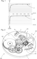
figure 1 comporte un double graphique comportant sur la même abscisse le rapport entre l'inertie de l'élément inertiel du résonateur et l'inertie de l'ancre, et qui, en ordonnée montre, pour un exemple particulier de mécanisme, d'une part au niveau du graphique supérieur en partie positive l'allure du rendement du régulateur en %, et au niveau du graphique inférieur en partie négative l'allure du retard en secondes par jour; ces graphiques supérieur et inférieur sont établis pour une même géométrie d'échappement donnée, avec des valeurs particulières de facteur de qualité, d'angle de levée d'ancre, et d'amplitude de fonctionnement; - la
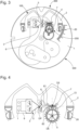
figure 2 représente, de façon schématisée, partielle, et en perspective, un mouvement d'horlogerie, avec une platine porteuse d'un mécanisme régulateur selon l'invention, comportant un résonateur à guidage flexible avec deux lames flexibles disposées sur deux niveaux parallèles et croisées en projection, fixées à la platine par l'intermédiaire d'un élément élastique, ce résonateur comportant un élément inertiel de grande étendue, en forme de lettre oméga, et dont la partie centrale, portée par les deux lames flexibles, porte une cheville agencée pour coopérer avec une ancre symétrique, dont le pivotage par un arbre métallique sur la platine n'est pas représenté, qui coopère elle-même avec une roue d'échappement classique; - la
figure 3 représente, en vue en plan, le seul mécanisme régulateur de lafigure 2 , agencé sur la platine du mouvement; - la
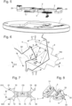
figure 4 représente, en vue en plan, le détail du mécanisme régulateur de lafigure 2 ; - la
figure 5 représente, en perspective partiellement éclatée, le mécanisme régulateur de lafigure 2 ; - la
figure 6 représente, en vue en plan, un détail de la zone de coopération entre la cheville de plateau de l'élément inertiel du résonateur, et la fourchette de l'ancre, représentée dans une position de butée sur une goupille de limitation; - la
figure 7 représente, en vue en plan, l'ancre du mécanisme de lafigure 2 , en forme de cornes de bovin watusi ; - la
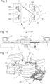
figure 8 représente, en vue en plan, le guidage flexible du mécanisme de lafigure 2 ; - la
figure 9 représente, en vue en plan, une exécution particulière d'un niveau du guidage flexible du mécanisme de lafigure 2 ; - la
figure 10 représente, en vue de côté, le mécanisme régulateur de lafigure 2 ; - la
figure 11 représente, en perspective, un détail du mécanisme régulateur de lafigure 2 , concernant des butées anti-choc au niveau de sa platine; - les
figures 12 à 14 sont des graphiques comportant en abscisse le couple appliqué au mobile d'échappement, et en ordonnée, respectivement l'amplitude mesurée en degrés sur lafigure 12 , le retard en secondes par jour sur lafigure 13 , et le rendement du régulateur en % sur lafigure 14 ; - la
figure 15 est un schéma-blocs qui représente une montre comportant un mouvement avec des moyens moteurs et un mécanisme régulateur selon l'invention ; - les
figures 16 à 19 représentent, en vue en plan, des étapes de la cinématique, déjà symbolisée par lafigure 6 , au niveau de l'ellipse de balancier, de la fourchette de l'ancre de lafigure 7 , et du mobile d'échappement ici constitué par une roue d'échappement traditionnelle : -
figure 16 : repos de la roue d'échappement sur la palette d'entrée, arc libre du résonateur; -
figure 17 : dégagement ; -
figure 18 : début de l'impulsion ; -
figure 19 : repos de la roue d'échappement sur la palette de sortie, arc libre du résonateur, et mise en sécurité.
- there
figure 1 includes a double graph showing on the same abscissa the ratio between the inertia of the inertial element of the resonator and the inertia of the anchor, and which, on the ordinate, shows, for a particular example of mechanism, on the one hand at the level of the upper graph in positive part the shape of the efficiency of the regulator in %, and at the level of the lower graph in negative part the shape of the delay in seconds per day; these upper and lower graphs are established for the same given escapement geometry, with particular values of quality factor, anchor lift angle, and operating amplitude; - there
figure 2 represents, in a schematic, partial, and perspective manner, a clockwork movement, with a plate carrying a regulating mechanism according to the invention, comprising a flexible-guided resonator with two flexible blades arranged on two parallel levels and crossed in projection, fixed to the plate by means of an elastic element, this resonator comprising a large inertial element, in the shape of an omega letter, and the central part of which, carried by the two flexible blades, carries a pin arranged to cooperate with a symmetrical anchor, the pivoting of which by a metal shaft on the plate is not shown, which itself cooperates with a conventional escape wheel; - there
figure 3 represents, in plan view, the only regulatory mechanism of thefigure 2 , arranged on the movement plate; - there
figure 4 represents, in plan view, the detail of the regulating mechanism of thefigure 2 ; - there
figure 5 represents, in partially exploded perspective, the regulatory mechanism of thefigure 2 ; - there
figure 6 represents, in plan view, a detail of the cooperation zone between the plate pin of the inertial element of the resonator, and the fork of the anchor, represented in a stop position on a limiting pin; - there
figure 7 represents, in plan view, the anchor of the mechanism of thefigure 2 , in the shape of watusi cattle horns; - there
figure 8 shows, in plan view, the flexible guidance of the mechanism of thefigure 2 ; - there
figure 9 represents, in plan view, a particular execution of a level of the flexible guidance of the mechanism of thefigure 2 ; - there
figure 10 represents, in side view, the regulatory mechanism of thefigure 2 ; - there
figure 11 represents, in perspective, a detail of the regulatory mechanism of thefigure 2 , concerning anti-shock stops at the level of its plate; - THE
Figures 12 to 14 are graphs with the torque applied to the escapement wheel on the abscissa, and the amplitude measured in degrees on the ordinate, respectively.figure 12 , the delay in seconds per day on thefigure 13 , and the regulator efficiency in % on thefigure 14 ; - there
figure 15 is a block diagram which represents a watch comprising a movement with motor means and a regulating mechanism according to the invention; - THE
Figures 16 to 19 represent, in plan view, stages of the kinematics, already symbolized by thefigure 6 , at the level of the balance ellipse, of the fork of the anchor of thefigure 7 , and the escapement wheel here constituted by a traditional escape wheel: -
figure 16 : rest of the escape wheel on the entry pallet, free arc of the resonator; -
figure 17 : clearance; -
figure 18 : start of the pulse; -
figure 19 : resting of the escape wheel on the output pallet, free arc of the resonator, and safety.
L'invention combine un résonateur à guidage flexible rotatif, afin d'augmenter la réserve de marche et la précision, avec un échappement à ancre optimisé pour conserver des pertes dynamiques acceptables et limiter l'effet chronométrique du dégagement.The invention combines a rotating flexible-guided resonator, in order to increase the power reserve and precision, with an anchor escapement optimized to maintain acceptable dynamic losses and limit the chronometric effect of the clearance.
L'invention concerne ainsi un mécanisme régulateur 300 d'horlogerie, comportant, agencés sur une platine 1, un mécanisme résonateur 100 de facteur de qualité Q, et un mécanisme d'échappement 200, lequel est soumis à un couple de moyens moteurs 400 que comporte un mouvement 500.The invention thus relates to a
Ce mécanisme résonateur 100 comportant un élément inertiel 2 qui est agencé pour osciller par rapport à la platine 1. Cet élément inertiel 2 est soumis à l'action de moyens de rappel élastique 3 fixés directement ou indirectement à la platine 1. L'élément inertiel 2 est agencé pour coopérer indirectement avec un mobile d'échappement 4, notamment une roue d'échappement, que comporte le mécanisme d'échappement 200, et qui pivote autour d'un axe d'échappement DE.This
Le mécanisme résonateur 100 est un résonateur rotatif à pivot virtuel, autour d'un axe principal DP, à guidage flexible comportant au moins deux lames flexibles 5, et comporte une cheville de plateau 6 solidaire de l'élément inertiel 2. Le mécanisme d'échappement 200 comporte une ancre 7, laquelle pivote autour d'un axe secondaire DS et comporte une fourchette d'ancre 8 agencée pour coopérer avec la cheville de plateau 6, et est ainsi un mécanisme d'échappement libre: dans son cycle de fonctionnement, le mécanisme résonateur 100 possède au moins une phase de liberté où la cheville de plateau 6 est à distance de la fourchette d'ancre 8. L'angle de levée de résonateur β, pendant lequel la cheville de plateau 6 est en contact avec la fourchette d'ancre 8, est inférieur à 10°.The
Etant donnée une géométrie d'échappement particulière, et une amplitude de fonctionnement particulière, notamment 8°, les simulations multicorps dynamiques (c'est-à-dire relatives à un ensemble de plusieurs composants dont chacun est affecté d'une masse et d'une distribution d'inertie particulière) permettent d'évaluer le rendement et le retard de ce mécanisme d'échappement en fonction du rapport d'inertie entre l'inertie de l'élément inertiel et l'inertie de l'ancre, ce que des simulations cinématiques usuelles ne permettent pas d'établir. Tel que visible sur la
Le modèle analytique du système a ainsi montré que, si on veut limiter les pertes dynamiques, une condition particulière lie l'inertie de l'ancre, l'inertie de l'élément inertiel, le facteur de qualité du résonateur, et les angles de levée de l'ancre et de l'élément inertiel : pour un coefficient ε de pertes dynamiques, l'inertie IB de l'élément inertiel 2 par rapport à l'axe principal DP d'une part, et l'inertie IA de l'ancre 7 par rapport à l'axe secondaire DS d'autre part, sont telles que le rapport IB/IA est supérieur à 2Q.α2/(ε.π.β2), où α est l'angle de levée de l'ancre qui correspond à la course angulaire maximale de la fourchette d'ancre 8.The analytical model of the system thus showed that, if we want to limit dynamic losses, a particular condition links the inertia of the anchor, the inertia of the inertial element, the quality factor of the resonator, and the lifting angles of the anchor and the inertial element: for a coefficient ε of dynamic losses, the inertia I B of the
Plus particulièrement, si on veut limiter les pertes dynamiques à un facteur ε=10%, l'inertie IB de l'élément inertiel 2 par rapport à l'axe principal DP d'une part, et l'inertie IA de l'ancre 7 par rapport à l'axe secondaire DS d'autre part, sont telles que le rapport IB/IA est supérieur à 2Q.α2/(0.1.π.β2), où α est l'angle de levée de l'ancre qui correspond à la course angulaire maximale de la fourchette d'ancre 8.More particularly, if we want to limit the dynamic losses to a factor ε=10%, the inertia I B of the
Plus particulièrement, l'angle de levée de résonateur β, qui est un angle global, pris de part et d'autre de la position de repos, est inférieur au double de l'angle d'amplitude dont s'écarte au maximum l'élément inertiel 2 par rapport à une position de repos, dans un seul sens de son mouvement.More particularly, the resonator lift angle β, which is an overall angle, taken on either side of the rest position, is less than twice the amplitude angle by which the
Plus particulièrement, l'angle d'amplitude, dont s'écarte au maximum l'élément inertiel 2 par rapport à une position de repos, est compris entre 5° et 40°.More particularly, the amplitude angle, from which the
Plus particulièrement, lors de chaque alternance, dans une phase de contact la cheville de plateau 6 pénètre dans la fourchette d'ancre 8 avec une course de pénétration P supérieure à 100 micromètres, et dans une phase de dégagement la cheville de plateau 6 reste à distance de la fourchette d'ancre 8 avec une distance de sécurité S supérieure à 25 micromètres.More particularly, during each alternation, in a contact phase the
La fourchette 8 de l'ancre 7 est ainsi élargie par rapport à ce que serait une fourchette classique d'ancre suisse, beaucoup plus étroite et autorisant moins de liberté à l'ellipse 6, qui n'arriverait pas à rentrer et sortir de la fourchette d'une ancre suisse classique avec une aussi petite amplitude angulaire. Ce concept de fourchette élargie permet de faire fonctionner un échappement à ancre quand bien même l'amplitude du résonateur est beaucoup plus faible que dans un balancier spiral classique, ce qui est particulièrement intéressant pour des résonateurs à guidage flexibles, qui ont une faible amplitude, comme dans le cas d'espèce. En effet, il est important que, pendant le cycle de fonctionnement le balancier soit entièrement libre à certains instants.
Et la cheville de plateau 6 et la fourchette d'ancre 8 sont avantageusement dimensionnées pour que la largeur L de la fourchette d'ancre 8 soit supérieure à (P+S)/sin(α/2+β/2), la course de pénétration P et la distance de sécurité S étant mesurées radialement par rapport à l'axe principal DP.And the
La largeur utile L1 de la cheville de plateau 6, visible sur la
L'observation des figures montre une action complémentaire sur le positionnement de l'ellipse 6, située beaucoup plus loin de l'axe de rotation du balancier 2 que dans un mécanisme d'échappement classique : le rayon supérieur combiné avec un angle de pivotement inférieur permet de maintenir une course curviligne équivalente de l'ellipse 6, ce qui est nécessaire pour lui permettre d'accomplir sa fonction de distribution-comptage. L'utilisation d'un balancier de grand diamètre est donc particulièrement intéressante.Observation of the figures shows a complementary action on the positioning of
Plus particulièrement, l'excentration E2 de l'ellipse 6 par rapport à l'axe du balancier, et l'excentration E7 de la corne de fourchette 8 par rapport à l'axe de l'ancre 7, sont comprises entre 40% et 60% de l'entraxe E entre l'axe de l'ancre 7 et l'axe du balancier. Plus particulièrement, l'excentration E2 est comprise entre 55% et 60% de l'entraxe E, et l'excentration E7 est comprise entre 40% et 45% de l'entraxe E. Plus particulièrement, la zone d'interférence entre l'ellipse 6 et la fourchette 8 s'étend sur 5% à 10% de l'entraxe E.More particularly, the eccentricity E2 of the
Ainsi, l'invention définit, par construction, un nouveau tracé cheville-fourchette, qui présente une caractéristique bien particulière, selon laquelle les cornes de la fourchette sont plus écartées, et la cheville est plus large, que pour un mécanisme à ancre suisse de type connu avec un angle de levée usuel de 50°.Thus, the invention defines, by construction, a new pin-fork layout, which has a very particular characteristic, according to which the horns of the fork are further apart, and the pin is wider, than for a Swiss anchor mechanism of known type with a usual lifting angle of 50°.
Ainsi, en élargissant sensiblement la fourchette de l'ancre par rapport aux proportions habituelles, on peut encore dimensionner un échappement à ancre suisse avec un très petit angle de levée, par exemple de l'ordre de 10°.Thus, by significantly widening the anchor fork compared to the usual proportions, it is still possible to size a Swiss anchor escapement with a very small lift angle, for example of the order of 10°.
La
Les
Et on comprend l'intérêt, pour maximiser le rendement du résonateur, de la relation particulière, exposée plus haut et qui lie l'inertie de l'élément inertiel et l'inertie de l'ancre, dans un rapport supérieur à 10000.And we understand the interest, to maximize the efficiency of the resonator, of the particular relationship, exposed above and which links the inertia of the inertial element and the inertia of the anchor, in a ratio greater than 10000.
Il est alors particulièrement intéressant de disposer d'une ancre à la fois très petite et très légère, et d'un balancier de grades dimensions et de forte masse.It is therefore particularly interesting to have an anchor that is both very small and very light, and a balance wheel of large dimensions and high mass.
Plus particulièrement, l'ancre 7 est en silicium, qui permet une exécution miniaturisée et très précise, avec une densité inférieure au tiers de celle de l'acier. Le fait d'avoir une ancre en silicium permet de diminuer son inertie par rapport à une ancre métallique. Une faible inertie de l'ancre par rapport au balancier est cruciale pour avoir un rendement correct à faible amplitude et haute fréquence, dans le présent cas des résonateurs à guidages flexibles.More specifically, the
Le balancier est, quant à lui, quand la gamme de la montre l'autorise, avantageusement réalisé dans un métal ou alliage lourd, comportant de l'or, du platine, du tungstène, ou similaire, et peut comporter des masselottes de constitution analogue. A défaut le balancier est classiquement réalisé en alliage CuBe2 cuivre-béryllium, ou similaire, et lesté de masselottes d'équilibrage et/ou de masselottes de réglage en maillechort ou autre alliage.The balance wheel is, when the watch range allows it, advantageously made of a heavy metal or alloy, including gold, platinum, tungsten, or similar, and may include weights of similar constitution. Failing this, the balance wheel is conventionally made of CuBe2 copper-beryllium alloy, or similar, and weighted with balancing weights and/or adjustment weights made of nickel silver or other alloy.
Plus particulièrement cette ancre 7 est sur un niveau unique de silicium, rapporté sur un arbre, métallique ou similaire, tel que céramique, ou autre, pivoté par rapport à la platine 1.More particularly, this
Plus particulièrement, le mobile d'échappement 4 est une roue d'échappement en silicium.More specifically,
Plus particulièrement, le mobile d'échappement 4 est une roue d'échappement qui est ajourée pour minimiser son inertie par rapport à son axe de pivotement DE.More particularly, the
Plus particulièrement, l'ancre 7 est ajourée pour minimiser son inertie IA par rapport à l'axe secondaire DS.More particularly, the
De préférence, l'ancre 7 est symétrique par rapport à l'axe secondaire DS, de façon à éviter tout balourd, et éviter les couples parasites lors de chocs linéaires, notamment en translation. Un avantage supplémentaire est alors la grande facilité d'assemblage de ce très petit composant, que l'opérateur effectuant le montage peut manipuler de n'importe quel côté.Preferably, the
La
Plus particulièrement, la plus grande dimension de l'élément inertiel 2 est plus grande que la moitié de la plus grande dimension de la platine 1.More particularly, the largest dimension of the
Plus particulièrement, l'axe principal DP, l'axe secondaire DS et l'axe de pivotement du mobile d'échappement 4, sont disposés selon un pointage à angle droit dont le sommet est sur l'axe secondaire DS. On comprend qu'ainsi, en référence à une ancre suisse classique en forme de té avec une baguette et deux bras, on supprime la baguette, qui devient l'un des deux bras 76, visible sur la
La comparaison avec l'ancre suisse est à poursuivre, en ce qui concerne les moyens de prévention du renversement, usuellement constitués par un dard situé sur un plan déporté de l'ancre. Cette fonction est importante pour éviter tout coincement du balancier. De façon particulière, le balancier est dépourvu de petit plateau et donc d'encoche de plateau prévue pour coopérer avec un tel dard. Ici, du fait des faibles angles de pivotement, l'ellipse n'est jamais loin de la fourchette.The comparison with the Swiss anchor is to be continued, as regards the means of preventing overturning, usually constituted by a dart located on a plane offset from the anchor. This function is important to avoid any jamming of the balance. In particular, the balance is devoid of small plate and therefore a plate notch designed to cooperate with such a dart. Here, due to the small pivot angles, the ellipse is never far from the fork.
Selon l'invention telle que revendiquée, la fonction anti-renversement est alors avantageusement remplie par la combinaison du pourtour 60 en arc de cercle de l'ellipse 6, et par la surface correspondante 810, 820, de la corne d'ancre 81, 82 concernée : cette corne joue le rôle usuel d'un dard, et la circonférence de l'ellipse joue le rôle du petit plateau. L'avantage supplémentaire qui en résulte est que, pour ce qui concerne sa coopération avec l'ancre d'un seul niveau, le balancier peut être lui aussi, localement, à un seul niveau, ce qui simplifie sa fabrication et allège son coût.According to the invention as claimed, the anti-overturning function is then advantageously fulfilled by the combination of the circular arc-shaped
La conception d'une ancre à un seul niveau, qui simplifie grandement la fabrication de l'ancre, est possible uniquement parce que le renversement est ainsi empêché par la faible amplitude du résonateur, combinée à l'importante largeur de l'ellipse (largeur environ égale à la fourchette élargie).The design of a single-level anchor, which greatly simplifies the manufacture of the anchor, is possible only because overturning is thus prevented by the low amplitude of the resonator, combined with the large width of the ellipse (width approximately equal to the enlarged fork).
Plus particulièrement, le guidage flexible comporte deux lames flexibles 5 croisées en projection sur un plan perpendiculaire à l'axe principal DP, au niveau du pivot virtuel définissant l'axe principal DP, et situées dans deux niveaux parallèles et distincts. Plus particulièrement encore, les deux lames flexibles 5, en projection sur un plan perpendiculairement à l'axe principal DP, forment entre elles un angle compris entre 59.5° et 69.5°, et se croisent entre 10.75% et 14.75% de leur longueur, de façon à procurer au mécanisme résonateur 100 un défaut volontaire d'isochronisme opposé au défaut de retard à l'échappement du mécanisme d'échappement 200.More particularly, the flexible guide comprises two
Le résonateur présente ainsi une courbe d'anisochronisme qui compense le retard provoqué par l'échappement. C'est-à-dire que le résonateur libre est conçu avec un défaut d'isochronisme opposé au défaut provoqué par l'échappement à ancre. On compense donc le retard à l'échappement par la conception du résonateur.The resonator thus has an anisochronism curve which compensates for the delay caused by the escapement. That is to say that the free resonator is designed with an isochronism defect opposite to the defect caused by the lever escapement. The escapement delay is therefore compensated for by the design of the resonator.
Plus particulièrement les deux lames flexibles 5 sont identiques et sont positionnées en symétrie. Plus particulièrement encore, chaque lame flexible 5 appartient à un ensemble monobloc 50, d'une seule pièce avec deux parties massives 51, 55, et avec ses premiers moyens d'alignement 52A, 52B, et de fixation 54 sur la platine 1, ou, avantageusement et tel que visible sur la
Le guidage flexible 3 à lames croisées 5 est avantageusement constitué de deux ensembles monobloc 50 pièces en silicium identiques, assemblés en symétrie pour former le croisement des lames, et alignés précisément l'un par rapport à l'autre grâce aux moyens d'alignement intégrés et à des moyens auxiliaires tels que des goupilles et des vis, non représentés sur les figures.The
Ainsi, plus particulièrement, au moins le mécanisme résonateur 100 est fixé sur une lame élastique intermédiaire de suspension 9 fixée à la platine 1 et agencée pour autoriser un déplacement mécanisme résonateur 100 selon la direction de l'axe principal DP, et la platine 1 comporte au moins une butée antichoc 11, 12, au moins selon la direction de l'axe principal DP, et de préférence au moins deux telles butées antichoc 11,12, qui sont agencées pour coopérer avec au moins un élément rigide de l'élément inertiel 2, par exemple un flasque 21 ou 22 rapporté lors de l'assemblage de l'élément inertiel avec le guidage flexible 3 comportant les lames 5.Thus, more particularly, at least the
La lame élastique de suspension 9, ou un dispositif similaire, permet des déplacements de tout le résonateur 100 sensiblement selon la direction définie par l'axe de rotation virtuel DP du guidage. Le but de ce dispositif est d'éviter que les lames 5 ne se cassent en cas de choc transversal selon la direction DP.The
La
Plus particulièrement, l'élément inertiel 2 comporte des masselottes 20 de réglage de la marche et du balourd.More particularly, the
Plus particulièrement, la cheville de plateau 6 est monobloc avec une lame flexible 5, ou plus particulièrement, un tel ensemble monobloc 50 tel qu'illustré sur les figures.More particularly, the
Plus particulièrement, l'ancre 7 comporte des surfaces d'appui agencées pour coopérer en appui avec des dents que comporte le mobile d'échappement 4 et pour limiter la course angulaire de l'ancre 7. Ces appuis permettent de limiter la course angulaire de l'ancre, comme le feraient des étoqueaux. La course angulaire de l'ancre 78 peut d'ailleurs être classiquement limitée par des goupilles de limitation 700.More particularly, the
Plus particulièrement le guidage flexible 3 est en silicium oxydé pour compenser les effets de la température sur la marche du mécanisme régulateur 300.More particularly, the
L'invention concerne encore un mouvement d'horlogerie 500 comportant des moyens moteurs 400, et un tel mécanisme régulateur 300, dont le mécanisme d'échappement 200 est soumis au couple de ces moyens moteurs 400.The invention also relates to a
Les graphiques des
L'invention concerne encore une montre 1000, plus particulièrement une montre mécanique, comportant un tel mouvement 500, et/ou un tel mécanisme régulateur 300.The invention also relates to a
En somme, la présente invention permet d'augmenter la réserve de marche et/ou la précision des montres mécaniques actuelles. Pour une taille de mouvement donné, on peut quadrupler l'autonomie de la montre et à doubler le pouvoir réglant de la montre. Cela revient à dire que l'invention permet un gain d'un facteur 8 sur les performances du mouvement.In short, the present invention makes it possible to increase the power reserve and/or the precision of current mechanical watches. For a given movement size, the autonomy of the watch can be quadrupled and the regulating power of the watch doubled. This amounts to saying that the invention allows a gain of a factor of 8 on the performance of the movement.
Claims (10)
- Horological regulator mechanism (300) comprising, arranged on a plate (1), a resonator mechanism (100) with a quality factor Q, and an escapement mechanism (200) which is arranged to be subjected to a torque from drive means (400) comprised in a movement (500), said resonator mechanism (100) comprising an inertial element (2) arranged to oscillate with respect to said plate (1), said inertial element (2) being subjected to the action of resilient return means (3) directly or indirectly attached to said plate (1), and said inertial element (2) being arranged to cooperate indirectly with an escape wheel set (4) comprised in said escapement mechanism (200), wherein said resonator mechanism (100) is a resonator with a virtual pivot rotating about a main axis (DP), with a flexure bearing comprising at least two flexible blades (5), and comprising an impulse pin (6) integral with said inertial element (2), wherein said escapement mechanism (200) comprises a pallet-lever (7) pivoting about a secondary axis (DS) and comprising a pallet-lever fork (8) arranged to cooperate with said impulse pin (6), and is a detached escapement mechanism, in the operating cycle of which, said resonator mechanism (100) has at least one phase of freedom in which said impulse pin (6) is at a distance from said pallet-lever fork (8), wherein said pallet-lever (7) is arranged in a single level and, in order for it to cooperate with said single-level pallet-lever (7), the balance (2) is also, locally, arranged in a single level, characterised in that the anti-overbanking function of said resonator mechanism (100) is ensured by the combination of an arcuate periphery (60) of said impulse pin (6), and by the corresponding antagonistic surface (810; 820) of a relevant horn (81; 82) of said pallet-lever (7).
- Regulator mechanism (300) according to claim 1, characterised in that the overall angle of resonator lift (β), during which said impulse pin (6) is in contact with said pallet-lever fork (8), is less than 10°.
- Regulator mechanism (300) according to claim 1 or 2, characterised in that, during each vibration, in a contact phase, said impulse pin (6) penetrates said pallet-lever fork (8) with a depth of travel (P) greater than 100 micrometres, and in a release phase, said impulse pin (6) remains at a distance from said pallet-lever fork (8) with a safety distance (S) greater than 25 micrometres, and in that said impulse pin (6) and said pallet-lever fork (8) are dimensioned so that the width (L) of said pallet-lever fork (8) is greater than (P+S)/sin(α/2+β/2), said depth of travel (P) and said safety distance (S) being measured radially with respect to said main axis (DP), where α is the overall pallet-lever lift angle which corresponds to the maximum angular travel of said pallet-lever fork (8), and where β is the overall resonator lift angle, during which said impulse pin (6) is in contact with said pallet-lever fork (8).
- Regulator mechanism (300) according to one of claims 1 to 3, characterised in that said pallet-lever (7) is made of a single level of silicon, attached to an arbor pivoted with respect to said plate (1).
- Regulator mechanism (300) according to one of claims 1 to 4, characterised in that said escape wheel set (4) is a silicon escape wheel.
- Regulator mechanism (300) according to one of claims 1 to 5, characterised in that said escape wheel set (4) is an escape wheel which is openworked to minimise its inertia relative to its pivot axis.
- Regulator mechanism (300) according to one of claims 1 to 6, characterised in that said pallet-lever (7) is openworked to minimise its inertia (IA) relative to said secondary axis (DS).
- Regulator mechanism (300) according to one of claims 1 to 7, characterised in that said pallet-lever (7) is symmetrical with respect to said secondary axis (DS).
- Horological movement (500) comprising drive means (400) and a regulator mechanism (300) according to one of claims 1 to 8, in which said escapement mechanism (200) is subjected to the torque from said drive means (400).
- Watch (1000) comprising a movement (500) according to claim 9, and/or a regulator mechanism (300) according to one of claims 1 to 8.
Applications Claiming Priority (2)
| Application Number | Priority Date | Filing Date | Title |
|---|---|---|---|
| EP16200152.3A EP3327515B1 (en) | 2016-11-23 | 2016-11-23 | Flexibly guided rotary resonator maintained by a free escapement with pallet |
| PCT/EP2017/069039 WO2018099616A2 (en) | 2016-11-23 | 2017-07-27 | Rotary resonator with a flexible guide system based on a detached lever escapement |
Publications (2)
| Publication Number | Publication Date |
|---|---|
| EP3545366A2 EP3545366A2 (en) | 2019-10-02 |
| EP3545366B1 true EP3545366B1 (en) | 2025-01-15 |
Family
ID=57391852
Family Applications (9)
| Application Number | Title | Priority Date | Filing Date |
|---|---|---|---|
| EP16200152.3A Active EP3327515B1 (en) | 2016-11-23 | 2016-11-23 | Flexibly guided rotary resonator maintained by a free escapement with pallet |
| EP17745180.4A Active EP3545365B1 (en) | 2016-11-23 | 2017-07-27 | Flexibly guided rotary resonator maintained by a free escapement with pallets |
| EP17749674.2A Active EP3545367B1 (en) | 2016-11-23 | 2017-07-27 | Flexibly guided rotary resonator maintained by a free escapement with pallet |
| EP17745179.6A Active EP3545364B1 (en) | 2016-11-23 | 2017-07-27 | Flexibly guided rotary resonator maintained by a free escapement with pallets |
| EP17745178.8A Active EP3545363B1 (en) | 2016-11-23 | 2017-07-27 | Flexibly guided rotary resonator maintained by a free escapement with pallet |
| EP17746073.0A Active EP3545366B1 (en) | 2016-11-23 | 2017-07-27 | Flexibly guided rotary resonator maintained by a free escapement with pallet |
| EP17752312.3A Active EP3545368B1 (en) | 2016-11-23 | 2017-07-27 | Flexibly guided rotary resonator maintained by a free escapement with pallet |
| EP17794727.2A Active EP3545369B1 (en) | 2016-11-23 | 2017-11-07 | Flexibly guided rotary resonator maintained by a free escapement with pallet |
| EP17803933.5A Active EP3545370B1 (en) | 2016-11-23 | 2017-11-22 | Rotary resonator with a flexible guide system based on a detached lever escapement |
Family Applications Before (5)
| Application Number | Title | Priority Date | Filing Date |
|---|---|---|---|
| EP16200152.3A Active EP3327515B1 (en) | 2016-11-23 | 2016-11-23 | Flexibly guided rotary resonator maintained by a free escapement with pallet |
| EP17745180.4A Active EP3545365B1 (en) | 2016-11-23 | 2017-07-27 | Flexibly guided rotary resonator maintained by a free escapement with pallets |
| EP17749674.2A Active EP3545367B1 (en) | 2016-11-23 | 2017-07-27 | Flexibly guided rotary resonator maintained by a free escapement with pallet |
| EP17745179.6A Active EP3545364B1 (en) | 2016-11-23 | 2017-07-27 | Flexibly guided rotary resonator maintained by a free escapement with pallets |
| EP17745178.8A Active EP3545363B1 (en) | 2016-11-23 | 2017-07-27 | Flexibly guided rotary resonator maintained by a free escapement with pallet |
Family Applications After (3)
| Application Number | Title | Priority Date | Filing Date |
|---|---|---|---|
| EP17752312.3A Active EP3545368B1 (en) | 2016-11-23 | 2017-07-27 | Flexibly guided rotary resonator maintained by a free escapement with pallet |
| EP17794727.2A Active EP3545369B1 (en) | 2016-11-23 | 2017-11-07 | Flexibly guided rotary resonator maintained by a free escapement with pallet |
| EP17803933.5A Active EP3545370B1 (en) | 2016-11-23 | 2017-11-22 | Rotary resonator with a flexible guide system based on a detached lever escapement |
Country Status (6)
| Country | Link |
|---|---|
| US (6) | US11520289B2 (en) |
| EP (9) | EP3327515B1 (en) |
| JP (6) | JP6931392B2 (en) |
| CN (6) | CN110023846B (en) |
| CH (1) | CH713150A2 (en) |
| WO (8) | WO2018095593A2 (en) |
Families Citing this family (20)
| Publication number | Priority date | Publication date | Assignee | Title |
|---|---|---|---|---|
| CH713151B1 (en) * | 2016-11-23 | 2020-09-30 | Swatch Group Res & Dev Ltd | Flexible blade for watchmaking, and manufacturing process. |
| EP3327515B1 (en) | 2016-11-23 | 2020-05-06 | ETA SA Manufacture Horlogère Suisse | Flexibly guided rotary resonator maintained by a free escapement with pallet |
| EP3425458A1 (en) * | 2017-07-07 | 2019-01-09 | ETA SA Manufacture Horlogère Suisse | Cleavable piece of a clock oscillator |
| EP3438762A3 (en) * | 2017-07-28 | 2019-03-13 | The Swatch Group Research and Development Ltd | Timepiece oscillator having flexible guides with wide angular travel |
| EP3561607B1 (en) | 2018-04-23 | 2022-03-16 | ETA SA Manufacture Horlogère Suisse | Collision protection of a resonator mechanism with rotatable flexible guiding |
| EP3561609B1 (en) * | 2018-04-23 | 2022-03-23 | ETA SA Manufacture Horlogère Suisse | Shock protection of a resonator mechanism with rotatable flexible guiding |
| JP6843191B2 (en) * | 2018-07-24 | 2021-03-17 | ザ・スウォッチ・グループ・リサーチ・アンド・ディベロップメント・リミテッド | Timekeeping oscillator with flexor bearings with long square strokes |
| US11454932B2 (en) * | 2018-07-24 | 2022-09-27 | The Swatch Group Research And Development Ltd | Method for making a flexure bearing mechanism for a mechanical timepiece oscillator |
| EP3627237B1 (en) * | 2018-09-20 | 2022-04-06 | ETA SA Manufacture Horlogère Suisse | Component made of micro-machinable material for resonator with high quality factor |
| JP7485506B2 (en) * | 2018-10-12 | 2024-05-16 | ロレックス・ソシエテ・アノニム | Regulators for small clock movements |
| US12287609B2 (en) | 2019-07-12 | 2025-04-29 | Patek Philippe Sa Geneve | Method for adjustment of a flexute pivot timepiece oscillator |
| EP3783445B1 (en) * | 2019-08-22 | 2023-06-14 | ETA SA Manufacture Horlogère Suisse | Timepiece regulator mechanism with high quality factor and with minimum lubrication |
| EP3812842B1 (en) * | 2019-10-24 | 2023-11-29 | The Swatch Group Research and Development Ltd | Device for guiding the pivoting of a pivoting mass and timepiece resonator mechanism |
| EP3812843B1 (en) * | 2019-10-25 | 2025-04-23 | ETA SA Manufacture Horlogère Suisse | Flexible guide and set of stacked flexible guides for rotary resonator mechanism, in particular for a clock movement |
| EP3926412A1 (en) * | 2020-06-16 | 2021-12-22 | Montres Breguet S.A. | Regulating mechanism of a timepiece |
| EP3971655A1 (en) * | 2020-09-18 | 2022-03-23 | ETA SA Manufacture Horlogère Suisse | Shock-proof protection with abutment for a resonator mechanism with rotatable flexible guiding |
| EP3982204A1 (en) * | 2020-10-08 | 2022-04-13 | The Swatch Group Research and Development Ltd | Timepiece resonator comprising at least one flexible guide |
| EP4134754A1 (en) | 2021-08-13 | 2023-02-15 | ETA SA Manufacture Horlogère Suisse | Inertial mass provided with a flexible inertial element, in particular for timepieces |
| EP4160323A1 (en) * | 2021-10-04 | 2023-04-05 | CSEM Centre Suisse d'Electronique et de Microtechnique SA - Recherche et Développement | Mechanical timepiece regulator comprising a self-starting semi-free escapement with low angle of lift |
| EP4187326A1 (en) * | 2021-11-29 | 2023-05-31 | Omega SA | Hairspring for timepiece resonator mechanism provided with a means for adjusting stiffness |
Citations (2)
| Publication number | Priority date | Publication date | Assignee | Title |
|---|---|---|---|---|
| CH703464A2 (en) * | 2010-07-19 | 2012-01-31 | Nivarox Sa | Oscillating mechanism e.g. escapement drive, for timepiece, has rigid elements fixed to different elements of movement, where rigid elements, elastic return units and intermediate rigid element are coplanar on plane and deformed on plane |
| WO2015097066A2 (en) * | 2013-12-23 | 2015-07-02 | Eta Sa Manufacture Horlogère Suisse | Mechanical timepiece movement with magnetic escapement |
Family Cites Families (41)
| Publication number | Priority date | Publication date | Assignee | Title |
|---|---|---|---|---|
| US2663139A (en) * | 1949-10-31 | 1953-12-22 | Gibbs Mfg And Res Corp | Pallet lever construction |
| NL94759C (en) * | 1952-07-14 | |||
| CH469299A (en) * | 1967-03-31 | 1969-04-15 | Centre Electron Horloger | Mechanical resonator for timepiece |
| GB1195432A (en) * | 1967-05-15 | 1970-06-17 | Horstmann Magnetics Ltd | Electromechanical Oscillators |
| CH1089267A4 (en) * | 1967-08-02 | 1970-01-30 | ||
| US3834155A (en) * | 1974-02-19 | 1974-09-10 | Timex Corp | Offset pallet lever for watch escapement |
| CH599585B5 (en) * | 1975-08-05 | 1978-05-31 | Ebauchesfabrik Eta Ag | |
| JPH02273323A (en) | 1989-04-14 | 1990-11-07 | Fuji Electric Co Ltd | Sputtering device for ferromagnetic material |
| CH698105B1 (en) * | 2004-10-20 | 2009-05-29 | Vaucher Mft Fleurier Sa | Device for winding and setting the time. |
| DE602007001230D1 (en) * | 2007-03-09 | 2009-07-16 | Eta Sa Mft Horlogere Suisse | Inhibition with tangential impulses |
| CH705276B1 (en) * | 2007-12-28 | 2013-01-31 | Chopard Technologies Sa | Body workout and transmission to a lever escapement, and exhaust tray being equipped and timepiece comprising them. |
| EP2230572B1 (en) | 2009-03-17 | 2012-01-25 | Nivarox-FAR S.A. | Radial gripping system for a timepiece component |
| CH700640B1 (en) * | 2009-03-19 | 2014-09-30 | Mhvj Manufacture Horlogère Vallée De Joux | Timepiece leaner and stronger. |
| CH701421B1 (en) * | 2009-07-10 | 2014-11-28 | Manuf Et Fabrique De Montres Et Chronomètres Ulysse Nardin Le Locle Sa | mechanical oscillator. |
| EP2363762B1 (en) * | 2010-03-04 | 2017-11-22 | Montres Breguet SA | Timepiece including a high-frequency mechanical movement |
| EP2407830B1 (en) * | 2010-07-15 | 2014-11-05 | Rolex Sa | Timepiece |
| CN103097965B (en) * | 2010-07-19 | 2015-05-13 | 尼瓦洛克斯-法尔股份有限公司 | Oscillating mechanism with elastic pivot and movable element for energy transfer |
| EP2413202B1 (en) * | 2010-07-30 | 2017-11-15 | ETA SA Manufacture Horlogère Suisse | Method for improving the wear and impact resistance of an horological component. Anchor for clock movement with wear and impact resistance |
| KR101208560B1 (en) | 2010-09-03 | 2012-12-05 | 엘지전자 주식회사 | Apparatus and method for performing scanning of assigned secondary carrier in a wireless access system |
| EP2652559B1 (en) * | 2010-12-14 | 2019-04-24 | Chopard Technologies SA | Lever, and escapement provided with such a lever |
| EP2557460A1 (en) * | 2011-08-12 | 2013-02-13 | Nivarox-FAR S.A. | Metallic pallets with polymer horns |
| EP2574994A1 (en) * | 2011-09-29 | 2013-04-03 | Asgalium Unitec SA | Resonator with tuning fork for mechanical timepiece movement |
| JP5918438B2 (en) * | 2012-03-29 | 2016-05-18 | ニヴァロックス−ファー ソシエテ アノニム | Flexible escape mechanism with movable frame |
| EP2706416B1 (en) * | 2012-09-07 | 2015-11-18 | The Swatch Group Research and Development Ltd | Constant force flexible anchor |
| CH706924A2 (en) * | 2012-09-07 | 2014-03-14 | Nivarox Sa | Escapement anchor for escapement mechanism of movement of timepiece i.e. watch, has head arranged to cooperate with escapement wheel, and fork arranged to cooperate with lever, where angular position of fork is variable relative to head |
| JP6355102B2 (en) * | 2013-09-04 | 2018-07-11 | セイコーインスツル株式会社 | Constant force devices, movements and mechanical watches |
| EP2863273B1 (en) * | 2013-10-16 | 2016-01-13 | Montres Breguet SA | Escapement mechanism for watch movement |
| EP2911012B1 (en) * | 2014-02-20 | 2020-07-22 | CSEM Centre Suisse d'Electronique et de Microtechnique SA - Recherche et Développement | Timepiece oscillator |
| EP2977830B1 (en) * | 2014-07-23 | 2017-08-30 | Nivarox-FAR S.A. | Constant-force escapement mechanism |
| EP3191896B1 (en) * | 2014-09-09 | 2019-04-24 | The Swatch Group Research and Development Ltd | Combined resonator having improved isochronism |
| EP3021174A1 (en) * | 2014-11-17 | 2016-05-18 | LVMH Swiss Manufactures SA | Monolithic timepiece regulator, timepiece movement and timepiece having such a timepiece regulator |
| EP3032352A1 (en) | 2014-12-09 | 2016-06-15 | LVMH Swiss Manufactures SA | Timepiece regulator, timepiece movement and timepiece having such a regulator |
| CH710537A2 (en) * | 2014-12-18 | 2016-06-30 | Swatch Group Res & Dev Ltd | Clock oscillator tuning fork. |
| CH710524A2 (en) * | 2014-12-18 | 2016-06-30 | Swatch Group Res & Dev Ltd | Resonator clockwork cross-band. |
| EP3254158B1 (en) * | 2015-02-03 | 2023-07-05 | ETA SA Manufacture Horlogère Suisse | Isochronous clock resonator |
| CH710759A2 (en) * | 2015-02-20 | 2016-08-31 | Nivarox Far Sa | Oscillator for a timepiece. |
| AU2016372408B2 (en) * | 2015-12-14 | 2021-05-13 | MAX-PLANCK-Gesellschaft zur Förderung der Wissenschaften e.V. | Water-soluble derivatives of 3,5-diphenyl-diazole compounds |
| PL230779B1 (en) * | 2016-06-03 | 2018-12-31 | Int Tobacco Machinery Poland Spolka Z Ograniczona Odpowiedzialnoscia | Urządzenie do identyfikacji parametrów fizycznych artykułów prętopodobnych przemysłu tytoniowego |
| WO2018017145A1 (en) * | 2016-07-22 | 2018-01-25 | Westinghouse Electric Company Llc | Spray methods for coating nuclear fuel rods to add corrosion resistant barrier |
| MX2019000984A (en) * | 2016-08-15 | 2019-07-04 | Givaudan Sa | Process for the preparation of indanones. |
| EP3327515B1 (en) | 2016-11-23 | 2020-05-06 | ETA SA Manufacture Horlogère Suisse | Flexibly guided rotary resonator maintained by a free escapement with pallet |
-
2016
- 2016-11-23 EP EP16200152.3A patent/EP3327515B1/en active Active
- 2016-11-23 CH CH01544/16A patent/CH713150A2/en unknown
-
2017
- 2017-07-27 CN CN201780072327.1A patent/CN110023846B/en active Active
- 2017-07-27 WO PCT/EP2017/069038 patent/WO2018095593A2/en not_active Ceased
- 2017-07-27 EP EP17745180.4A patent/EP3545365B1/en active Active
- 2017-07-27 EP EP17749674.2A patent/EP3545367B1/en active Active
- 2017-07-27 CN CN201780072284.7A patent/CN109983410B/en active Active
- 2017-07-27 JP JP2019526552A patent/JP6931392B2/en active Active
- 2017-07-27 EP EP17745179.6A patent/EP3545364B1/en active Active
- 2017-07-27 US US16/347,286 patent/US11520289B2/en active Active
- 2017-07-27 US US16/462,801 patent/US11487245B2/en active Active
- 2017-07-27 WO PCT/EP2017/069037 patent/WO2018095592A1/en not_active Ceased
- 2017-07-27 JP JP2019527346A patent/JP6931395B2/en active Active
- 2017-07-27 WO PCT/EP2017/069039 patent/WO2018099616A2/en not_active Ceased
- 2017-07-27 US US16/344,567 patent/US11619909B2/en active Active
- 2017-07-27 EP EP17745178.8A patent/EP3545363B1/en active Active
- 2017-07-27 JP JP2019527338A patent/JP6931394B2/en active Active
- 2017-07-27 EP EP17746073.0A patent/EP3545366B1/en active Active
- 2017-07-27 WO PCT/EP2017/069041 patent/WO2018095595A1/en not_active Ceased
- 2017-07-27 JP JP2019547760A patent/JP6828179B2/en active Active
- 2017-07-27 WO PCT/EP2017/069040 patent/WO2018095594A1/en not_active Ceased
- 2017-07-27 CN CN201780072276.2A patent/CN109983409B/en active Active
- 2017-07-27 CN CN201780072304.0A patent/CN110023845B/en active Active
- 2017-07-27 WO PCT/EP2017/069043 patent/WO2018095596A2/en not_active Ceased
- 2017-07-27 EP EP17752312.3A patent/EP3545368B1/en active Active
- 2017-11-07 US US16/462,812 patent/US11467537B2/en active Active
- 2017-11-07 CN CN201780072329.0A patent/CN110023847B/en active Active
- 2017-11-07 EP EP17794727.2A patent/EP3545369B1/en active Active
- 2017-11-07 WO PCT/EP2017/078497 patent/WO2018103978A2/en not_active Ceased
- 2017-11-07 JP JP2019547766A patent/JP6828180B2/en active Active
- 2017-11-22 CN CN201780072330.3A patent/CN110235064B/en active Active
- 2017-11-22 US US16/343,509 patent/US11493882B2/en active Active
- 2017-11-22 WO PCT/EP2017/080121 patent/WO2018095997A2/en not_active Ceased
- 2017-11-22 JP JP2019524176A patent/JP6810800B2/en active Active
- 2017-11-22 EP EP17803933.5A patent/EP3545370B1/en active Active
-
2019
- 2019-05-21 US US16/418,697 patent/US11675312B2/en active Active
Patent Citations (3)
| Publication number | Priority date | Publication date | Assignee | Title |
|---|---|---|---|---|
| CH703464A2 (en) * | 2010-07-19 | 2012-01-31 | Nivarox Sa | Oscillating mechanism e.g. escapement drive, for timepiece, has rigid elements fixed to different elements of movement, where rigid elements, elastic return units and intermediate rigid element are coplanar on plane and deformed on plane |
| WO2015097066A2 (en) * | 2013-12-23 | 2015-07-02 | Eta Sa Manufacture Horlogère Suisse | Mechanical timepiece movement with magnetic escapement |
| CH710025A2 (en) * | 2013-12-23 | 2016-02-29 | Eta Sa Manufacture Horlogère Suisse | Mechanical watch movement with magnetic escapement. |
Also Published As
Similar Documents
| Publication | Publication Date | Title |
|---|---|---|
| EP3545366B1 (en) | Flexibly guided rotary resonator maintained by a free escapement with pallet | |
| EP3382472A1 (en) | Guide bearing of a timepiece balance pivot | |
| EP2781965B1 (en) | Frame for a clockwork | |
| EP3435173A1 (en) | Mechanical movement with isochronous rotary resonator, which is not position-sensitive | |
| EP2466397B1 (en) | Rotating clock component with peripheral guide | |
| CH714361A2 (en) | Flexible guided rotary resonator serviced by a free anchor escapement. | |
| EP3185083A1 (en) | Mechanical timepiece mechanism with anchor escapement | |
| EP3971655A1 (en) | Shock-proof protection with abutment for a resonator mechanism with rotatable flexible guiding | |
| EP3761122B1 (en) | Timepiece escapement component, associated escapement mechanism and timepiece | |
| CH717880A2 (en) | Resonator mechanism with rotating flexible guide with shock protection with stop. | |
| EP3663868A1 (en) | Clock movement including a tourbillon with a fixed magnetic wheel | |
| EP4286959A1 (en) | Timepiece oscillator with flexible pivot | |
| CH704239A2 (en) | Single block watch making mobile e.g. escape mechanism, for use during movement of mechanical watch, has guide surface located close to plane so as to maintain mobile in recessed or overhang manner, where mobile does not have guide shaft | |
| CH717575A2 (en) | Clock movement comprising an inertial mass resonator with flexible guidance and an escapement mechanism. | |
| CH717573A2 (en) | Clock movement comprising an inertial mass resonator with flexible guidance and an escapement mechanism. | |
| CH717580A2 (en) | Clock movement comprising an inertial mass resonator and an escapement mechanism. | |
| CH717578A2 (en) | Clock movement comprising an inertial mass resonator and an escapement mechanism. |
Legal Events
| Date | Code | Title | Description |
|---|---|---|---|
| STAA | Information on the status of an ep patent application or granted ep patent |
Free format text: STATUS: UNKNOWN |
|
| STAA | Information on the status of an ep patent application or granted ep patent |
Free format text: STATUS: THE INTERNATIONAL PUBLICATION HAS BEEN MADE |
|
| PUAI | Public reference made under article 153(3) epc to a published international application that has entered the european phase |
Free format text: ORIGINAL CODE: 0009012 |
|
| STAA | Information on the status of an ep patent application or granted ep patent |
Free format text: STATUS: REQUEST FOR EXAMINATION WAS MADE |
|
| 17P | Request for examination filed |
Effective date: 20190821 |
|
| AK | Designated contracting states |
Kind code of ref document: A2 Designated state(s): AL AT BE BG CH CY CZ DE DK EE ES FI FR GB GR HR HU IE IS IT LI LT LU LV MC MK MT NL NO PL PT RO RS SE SI SK SM TR |
|
| AX | Request for extension of the european patent |
Extension state: BA ME |
|
| DAV | Request for validation of the european patent (deleted) | ||
| DAX | Request for extension of the european patent (deleted) | ||
| STAA | Information on the status of an ep patent application or granted ep patent |
Free format text: STATUS: EXAMINATION IS IN PROGRESS |
|
| 17Q | First examination report despatched |
Effective date: 20211011 |
|
| P01 | Opt-out of the competence of the unified patent court (upc) registered |
Effective date: 20230701 |
|
| GRAP | Despatch of communication of intention to grant a patent |
Free format text: ORIGINAL CODE: EPIDOSNIGR1 |
|
| STAA | Information on the status of an ep patent application or granted ep patent |
Free format text: STATUS: GRANT OF PATENT IS INTENDED |
|
| RIC1 | Information provided on ipc code assigned before grant |
Ipc: G04B 31/00 20060101ALI20240806BHEP Ipc: G04B 18/02 20060101ALI20240806BHEP Ipc: G04B 17/28 20060101ALI20240806BHEP Ipc: G04B 15/14 20060101ALI20240806BHEP Ipc: G04B 17/04 20060101ALI20240806BHEP Ipc: G04B 17/26 20060101ALI20240806BHEP Ipc: G04B 15/08 20060101AFI20240806BHEP |
|
| INTG | Intention to grant announced |
Effective date: 20240904 |
|
| GRAS | Grant fee paid |
Free format text: ORIGINAL CODE: EPIDOSNIGR3 |
|
| GRAA | (expected) grant |
Free format text: ORIGINAL CODE: 0009210 |
|
| STAA | Information on the status of an ep patent application or granted ep patent |
Free format text: STATUS: THE PATENT HAS BEEN GRANTED |
|
| AK | Designated contracting states |
Kind code of ref document: B1 Designated state(s): AL AT BE BG CH CY CZ DE DK EE ES FI FR GB GR HR HU IE IS IT LI LT LU LV MC MK MT NL NO PL PT RO RS SE SI SK SM TR |
|
| REG | Reference to a national code |
Ref country code: CH Ref legal event code: EP Ref country code: GB Ref legal event code: FG4D Free format text: NOT ENGLISH |
|
| REG | Reference to a national code |
Ref country code: DE Ref legal event code: R096 Ref document number: 602017087344 Country of ref document: DE |
|
| REG | Reference to a national code |
Ref country code: IE Ref legal event code: FG4D Free format text: LANGUAGE OF EP DOCUMENT: FRENCH |
|
| REG | Reference to a national code |
Ref country code: NL Ref legal event code: MP Effective date: 20250115 |
|
| PG25 | Lapsed in a contracting state [announced via postgrant information from national office to epo] |
Ref country code: NL Free format text: LAPSE BECAUSE OF FAILURE TO SUBMIT A TRANSLATION OF THE DESCRIPTION OR TO PAY THE FEE WITHIN THE PRESCRIBED TIME-LIMIT Effective date: 20250115 |
|
| PG25 | Lapsed in a contracting state [announced via postgrant information from national office to epo] |
Ref country code: RS Free format text: LAPSE BECAUSE OF FAILURE TO SUBMIT A TRANSLATION OF THE DESCRIPTION OR TO PAY THE FEE WITHIN THE PRESCRIBED TIME-LIMIT Effective date: 20250415 |
|
| PG25 | Lapsed in a contracting state [announced via postgrant information from national office to epo] |
Ref country code: FI Free format text: LAPSE BECAUSE OF FAILURE TO SUBMIT A TRANSLATION OF THE DESCRIPTION OR TO PAY THE FEE WITHIN THE PRESCRIBED TIME-LIMIT Effective date: 20250115 |
|
| PG25 | Lapsed in a contracting state [announced via postgrant information from national office to epo] |
Ref country code: PL Free format text: LAPSE BECAUSE OF FAILURE TO SUBMIT A TRANSLATION OF THE DESCRIPTION OR TO PAY THE FEE WITHIN THE PRESCRIBED TIME-LIMIT Effective date: 20250115 |
|
| PG25 | Lapsed in a contracting state [announced via postgrant information from national office to epo] |
Ref country code: ES Free format text: LAPSE BECAUSE OF FAILURE TO SUBMIT A TRANSLATION OF THE DESCRIPTION OR TO PAY THE FEE WITHIN THE PRESCRIBED TIME-LIMIT Effective date: 20250115 |
|
| PGFP | Annual fee paid to national office [announced via postgrant information from national office to epo] |
Ref country code: GB Payment date: 20250619 Year of fee payment: 9 |
|
| REG | Reference to a national code |
Ref country code: LT Ref legal event code: MG9D |
|
| PG25 | Lapsed in a contracting state [announced via postgrant information from national office to epo] |
Ref country code: NO Free format text: LAPSE BECAUSE OF FAILURE TO SUBMIT A TRANSLATION OF THE DESCRIPTION OR TO PAY THE FEE WITHIN THE PRESCRIBED TIME-LIMIT Effective date: 20250415 Ref country code: IS Free format text: LAPSE BECAUSE OF FAILURE TO SUBMIT A TRANSLATION OF THE DESCRIPTION OR TO PAY THE FEE WITHIN THE PRESCRIBED TIME-LIMIT Effective date: 20250515 |
|
| REG | Reference to a national code |
Ref country code: AT Ref legal event code: MK05 Ref document number: 1760230 Country of ref document: AT Kind code of ref document: T Effective date: 20250115 |
|
| PG25 | Lapsed in a contracting state [announced via postgrant information from national office to epo] |
Ref country code: HR Free format text: LAPSE BECAUSE OF FAILURE TO SUBMIT A TRANSLATION OF THE DESCRIPTION OR TO PAY THE FEE WITHIN THE PRESCRIBED TIME-LIMIT Effective date: 20250115 |
|
| PG25 | Lapsed in a contracting state [announced via postgrant information from national office to epo] |
Ref country code: LV Free format text: LAPSE BECAUSE OF FAILURE TO SUBMIT A TRANSLATION OF THE DESCRIPTION OR TO PAY THE FEE WITHIN THE PRESCRIBED TIME-LIMIT Effective date: 20250115 Ref country code: PT Free format text: LAPSE BECAUSE OF FAILURE TO SUBMIT A TRANSLATION OF THE DESCRIPTION OR TO PAY THE FEE WITHIN THE PRESCRIBED TIME-LIMIT Effective date: 20250515 |
|
| PGFP | Annual fee paid to national office [announced via postgrant information from national office to epo] |
Ref country code: FR Payment date: 20250620 Year of fee payment: 9 |
|
| PG25 | Lapsed in a contracting state [announced via postgrant information from national office to epo] |
Ref country code: BG Free format text: LAPSE BECAUSE OF FAILURE TO SUBMIT A TRANSLATION OF THE DESCRIPTION OR TO PAY THE FEE WITHIN THE PRESCRIBED TIME-LIMIT Effective date: 20250115 Ref country code: GR Free format text: LAPSE BECAUSE OF FAILURE TO SUBMIT A TRANSLATION OF THE DESCRIPTION OR TO PAY THE FEE WITHIN THE PRESCRIBED TIME-LIMIT Effective date: 20250416 |
|
| PG25 | Lapsed in a contracting state [announced via postgrant information from national office to epo] |
Ref country code: AT Free format text: LAPSE BECAUSE OF FAILURE TO SUBMIT A TRANSLATION OF THE DESCRIPTION OR TO PAY THE FEE WITHIN THE PRESCRIBED TIME-LIMIT Effective date: 20250115 |
|
| PG25 | Lapsed in a contracting state [announced via postgrant information from national office to epo] |
Ref country code: SE Free format text: LAPSE BECAUSE OF FAILURE TO SUBMIT A TRANSLATION OF THE DESCRIPTION OR TO PAY THE FEE WITHIN THE PRESCRIBED TIME-LIMIT Effective date: 20250115 |
|
| PG25 | Lapsed in a contracting state [announced via postgrant information from national office to epo] |
Ref country code: SM Free format text: LAPSE BECAUSE OF FAILURE TO SUBMIT A TRANSLATION OF THE DESCRIPTION OR TO PAY THE FEE WITHIN THE PRESCRIBED TIME-LIMIT Effective date: 20250115 |
|
| PG25 | Lapsed in a contracting state [announced via postgrant information from national office to epo] |
Ref country code: DK Free format text: LAPSE BECAUSE OF FAILURE TO SUBMIT A TRANSLATION OF THE DESCRIPTION OR TO PAY THE FEE WITHIN THE PRESCRIBED TIME-LIMIT Effective date: 20250115 |
|
| PGFP | Annual fee paid to national office [announced via postgrant information from national office to epo] |
Ref country code: DE Payment date: 20250620 Year of fee payment: 9 |
|
| PG25 | Lapsed in a contracting state [announced via postgrant information from national office to epo] |
Ref country code: IT Free format text: LAPSE BECAUSE OF FAILURE TO SUBMIT A TRANSLATION OF THE DESCRIPTION OR TO PAY THE FEE WITHIN THE PRESCRIBED TIME-LIMIT Effective date: 20250115 |
|
| REG | Reference to a national code |
Ref country code: DE Ref legal event code: R097 Ref document number: 602017087344 Country of ref document: DE |
|
| PGFP | Annual fee paid to national office [announced via postgrant information from national office to epo] |
Ref country code: CH Payment date: 20250801 Year of fee payment: 9 |
|
| PG25 | Lapsed in a contracting state [announced via postgrant information from national office to epo] |
Ref country code: EE Free format text: LAPSE BECAUSE OF FAILURE TO SUBMIT A TRANSLATION OF THE DESCRIPTION OR TO PAY THE FEE WITHIN THE PRESCRIBED TIME-LIMIT Effective date: 20250115 Ref country code: CZ Free format text: LAPSE BECAUSE OF FAILURE TO SUBMIT A TRANSLATION OF THE DESCRIPTION OR TO PAY THE FEE WITHIN THE PRESCRIBED TIME-LIMIT Effective date: 20250115 |
|
| PG25 | Lapsed in a contracting state [announced via postgrant information from national office to epo] |
Ref country code: RO Free format text: LAPSE BECAUSE OF FAILURE TO SUBMIT A TRANSLATION OF THE DESCRIPTION OR TO PAY THE FEE WITHIN THE PRESCRIBED TIME-LIMIT Effective date: 20250115 |
|
| PG25 | Lapsed in a contracting state [announced via postgrant information from national office to epo] |
Ref country code: SK Free format text: LAPSE BECAUSE OF FAILURE TO SUBMIT A TRANSLATION OF THE DESCRIPTION OR TO PAY THE FEE WITHIN THE PRESCRIBED TIME-LIMIT Effective date: 20250115 |
|
| PLBE | No opposition filed within time limit |
Free format text: ORIGINAL CODE: 0009261 |
|
| STAA | Information on the status of an ep patent application or granted ep patent |
Free format text: STATUS: NO OPPOSITION FILED WITHIN TIME LIMIT |
|
| 26N | No opposition filed |
Effective date: 20251016 |
|
| PG25 | Lapsed in a contracting state [announced via postgrant information from national office to epo] |
Ref country code: LU Free format text: LAPSE BECAUSE OF NON-PAYMENT OF DUE FEES Effective date: 20250727 |