EP3544465B1 - Steuerkasten mit kabelzugentlastung - Google Patents
Steuerkasten mit kabelzugentlastung Download PDFInfo
- Publication number
- EP3544465B1 EP3544465B1 EP17812254.5A EP17812254A EP3544465B1 EP 3544465 B1 EP3544465 B1 EP 3544465B1 EP 17812254 A EP17812254 A EP 17812254A EP 3544465 B1 EP3544465 B1 EP 3544465B1
- Authority
- EP
- European Patent Office
- Prior art keywords
- mains
- control box
- cable
- plug
- mains cable
- Prior art date
- Legal status (The legal status is an assumption and is not a legal conclusion. Google has not performed a legal analysis and makes no representation as to the accuracy of the status listed.)
- Active
Links
Images



Classifications
-
- H—ELECTRICITY
- H01—ELECTRIC ELEMENTS
- H01R—ELECTRICALLY-CONDUCTIVE CONNECTIONS; STRUCTURAL ASSOCIATIONS OF A PLURALITY OF MUTUALLY-INSULATED ELECTRICAL CONNECTING ELEMENTS; COUPLING DEVICES; CURRENT COLLECTORS
- H01R13/00—Details of coupling devices of the kinds covered by groups H01R12/70 or H01R24/00 - H01R33/00
- H01R13/58—Means for relieving strain on wire connection, e.g. cord grip, for avoiding loosening of connections between wires and terminals within a coupling device terminating a cable
-
- A—HUMAN NECESSITIES
- A47—FURNITURE; DOMESTIC ARTICLES OR APPLIANCES; COFFEE MILLS; SPICE MILLS; SUCTION CLEANERS IN GENERAL
- A47B—TABLES; DESKS; OFFICE FURNITURE; CABINETS; DRAWERS; GENERAL DETAILS OF FURNITURE
- A47B9/00—Tables with tops of variable height
-
- H—ELECTRICITY
- H01—ELECTRIC ELEMENTS
- H01R—ELECTRICALLY-CONDUCTIVE CONNECTIONS; STRUCTURAL ASSOCIATIONS OF A PLURALITY OF MUTUALLY-INSULATED ELECTRICAL CONNECTING ELEMENTS; COUPLING DEVICES; CURRENT COLLECTORS
- H01R13/00—Details of coupling devices of the kinds covered by groups H01R12/70 or H01R24/00 - H01R33/00
- H01R13/46—Bases; Cases
- H01R13/50—Bases; Cases formed as an integral body
-
- H—ELECTRICITY
- H01—ELECTRIC ELEMENTS
- H01R—ELECTRICALLY-CONDUCTIVE CONNECTIONS; STRUCTURAL ASSOCIATIONS OF A PLURALITY OF MUTUALLY-INSULATED ELECTRICAL CONNECTING ELEMENTS; COUPLING DEVICES; CURRENT COLLECTORS
- H01R13/00—Details of coupling devices of the kinds covered by groups H01R12/70 or H01R24/00 - H01R33/00
- H01R13/58—Means for relieving strain on wire connection, e.g. cord grip, for avoiding loosening of connections between wires and terminals within a coupling device terminating a cable
- H01R13/582—Means for relieving strain on wire connection, e.g. cord grip, for avoiding loosening of connections between wires and terminals within a coupling device terminating a cable the cable being clamped between assembled parts of the housing
Definitions
- the present invention relates to a control box system, comprising a control box, in particular for adjustable or adjustable furniture parts such.
- a control box in particular for adjustable or adjustable furniture parts such.
- B. height adjustable tables wherein the control box comprises: a control box housing and a power plug in a wall of the control box housing, the control box housing means for strain relief for a power cord with a power cord socket for connection to the power plug.
- the present invention is to be derived using the example of a height-adjustable table with a table top which is mounted on a base.
- the underframe has adjustable table legs.
- the length adjustment of the table legs and thus the height adjustment of the table is carried out by motors that are controlled via control boxes.
- the control boxes have mains plugs (built-in plugs) that are accessible from the outside of the control box housing.
- strain reliefs In housings for electrical devices, strain reliefs, in particular for a power cord, are known in principle.
- the strain relief often takes the form of metal or plastic clips. But there are also clamp-free or screw-free strain reliefs.
- a housing with a device for cable strain relief is known.
- pulling out is supposed to be a cable from an apparatus housing can be prevented.
- This is achieved in that two clamping wings connected to a housing part are provided. These clamping wings have edges which are parallel to one another and have a mutual spacing which is smaller than the diameter of the cable.
- the clamping wings are inclined towards the inside of the housing. If the cable is pressed between the parallel edges, this will be deformed. This creates a force that holds the cable.
- the attempt is made to pull the cable out of the device, it is held in place by the friction created between the surface of the cable and the edges of the clamping wings.
- the control box has one or more cable or line guides for guiding a line / a cable between two connecting sides of the control box housing, the line guides being designed as an integral part of the outside of the control box housing.
- the cable or line guide has at least one fastening element for a line.
- the known strain relief does not, however, provide strain relief for a power cable, requires a more complex design of the control box housing and is also not easy to use, since the respective cable has to be laboriously "inserted" into the cable guide on an outside of the control box housing accordingly can only be removed there again with greater effort.
- US 2010/233898 A1 discloses a control box, in particular for adjustable or adjustable furniture parts such.
- B. height adjustable or adjustable tables comprising a control box housing and a power plug in a wall of the control box housing, the control box housing having a means for strain relief for a power cord with a power cord socket for connection to the power plug, wherein the device for strain relief has a, in particular grooved, power cable clamp guide, which is arranged in the plugging direction of the power cable socket in front of the power plug and running transversely to the plugging direction in the control box housing and below the power plug so that the power cable socket, when plugged into the power plug, Mains cable clamping guide at the top at least partially closes such that the associated mains cable does not come out of the mains cable clamping guide.
- the present invention is therefore based on the object of providing a more simply designed strain relief for the power cord in a control box system of the type mentioned at the beginning.
- control box housing can be a housing for any electrical device.
- strain relief can be provided not only for a power cable, but in principle for any electrical cable.
- mains plug e.g. built-in plug
- connection socket device socket
- mains cable socket of the mains cable can also be interchanged, i.e. the male and female versions can be interchanged.
- the device for strain relief is preferably formed integrally with the control box housing, for example as an integral part of an outer side.
- the power cable clamping guide has at least two opposing, preferably parallel to one another extending, clamping noses or jaws.
- the power cable is guided in a clamping manner in the power cable clamping guide and the power cable socket, completely covering the power cable clamping guide in the plug-in direction, is plugged into the power plug while forming a loop in the power cable.
- the present invention is based on the surprising finding that due to the special arrangement and alignment of a cable clamp guide in relation to the power plug in the control box housing, the control box housing only needs to be modified slightly, so that this is not associated with great expense, and the strain relief simple way, including the power cord socket, can be implemented and reversed.
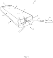
- Figure 1 shows a bar-shaped control box 10 for controlling a height-adjustable table (not shown).
- the control box 10 has a control box housing 12 with opposite connection sides 14 and 16, on which electrical cables can be connected, and a top side 18 and a bottom side 20 and side walls 22, 24.
- control box 10 has a mains plug (built-in plug) 26 in the middle of the connection side 14 in this example for supplying a control, etc. (not shown) located in the control box 10 with electrical energy.
- the mains plug 26 is arranged in such a way that a mains cable socket 28 (see Figures 2 and 3 ) a power cord 36 (see Figures 2 and 3 ) in this example must be plugged into the mains plug 26 essentially normal to the connection side 14.
- connection side 14 has a lower projection 30, which in this example extends over the entire width of the connection side 14 somewhat below the mains plug 26.
- two mutually opposite, mutually parallel protrusions or clamping walls 32, 32 as part of a power cable clamping guide 34 for clamping the power cable 36, the clamping walls having different geometries in this example.
- the height of the clamping walls 32 is selected so that the mains plug 26 is still accessible to the mains cable socket 28.
Landscapes
- Installation Of Indoor Wiring (AREA)
- Details Of Connecting Devices For Male And Female Coupling (AREA)
Description
- Die vorliegende Erfindung betrifft ein Steuerkasten-System, umfassend einen Steuerkasten, insbesondere für ein- bzw. verstellbare Möbelteile, wie z. B. in der Höhe ein- bzw. verstellbare Tische, wobei der Steuerkasten umfasst: ein Steuerkasten-Gehäuse und einen Netzstecker in einer Wand des Steuerkasten-Gehäuses, wobei das Steuerkasten-Gehäuse eine Einrichtung zur Zugentlastung für ein Netzkabel mit einer Netzkabelbuchse zur Verbindung mit dem Netzstecker aufweist.
- Am Beispiel eines höhenverstellbaren Tisches mit einer Tischplatte, die auf einem Untergestell montiert ist, soll die vorliegende Erfindung hergeleitet werden. Das Untergestell weist längenverstellbare Tischbeine auf. Die Längenverstellung der Tischbeine und damit die Höhenverstellung des Tisches erfolgt über Motoren, die über Steuerkästen angesteuert werden. Zur Stromversorgung weisen die Steuerkästen Netzstecker (Einbaustecker), die von der Außenseite des Steuerkasten-Gehäuses zugänglich sind, auf.
- Bei Gehäusen für elektrische Geräte sind Zugentlastungen insbesondere für ein Netzkabel grundsätzlich bekannt. Die Zugentlastung erfolgt häufig in Form von Metall- oder Kunststoffschellen. Es gibt aber auch schellen- oder schraubenlose Zugentlastungen. Beispielsweise aus der
CH 689 683 A5 - Aus der
EP 2 452 589 B1 ist eine Kabelzugentlastung für einen Steuerkasten bekannt. Der Steuerkasten weist eine oder mehrere Kabel- oder Leitungsführungen zum Führen einer Leitung/eines Kabels zwischen zwei Verbindungsseiten des Steuerkasten-Gehäuses auf, wobei die Leitungsführungen als integraler Teil der Außenseite des Steuerkasten-Gehäuses ausgestaltet sind. Zudem weist die Kabel- oder Leitungsführung mindestens ein Befestigungselement für eine Leitung auf. Die bekannt Zugentlastung dient jedoch nicht zur Zugentlastung für ein Netzkabel, erfordert eine komplexere Gestaltung des Steuerkasten-Gehäuses und ist auch in der Handhabung nicht einfach, da das jeweilige Kabel umständlich in die Kabelführung auf einer Außenseite des Steuerkasten-Gehäuses "eingelegt" werden muss und dementsprechend auch nur mit einem größeren Aufwand dort wieder herausnehmbar ist. -
US 2010/233898 A1 offenbart einen Steuerkasten, insbesondere für ein- beziehungsweise verstellbare Möbelteile, wie z. B. in der Höhe ein- beziehungsweise verstellbare Tische, umfassend ein Steuerkasten-Gehäuse und einen Netzstecker in einer Wand des Steuerkasten-Gehäuses, wobei das Steuerkasten-Gehäuse eine Einrichtung zur Zugentlastung für ein Netzkabel mit einer Netzkabelbuchse zur Verbindung mit dem Netzstecker aufweist, wobei die Einrichtung zur Zugentlastung eine, insbesondere rillenförmige, Netzkabelklemmführung aufweist, die in Steckrichtung der Netzkabelbuchse vor dem Netzstecker sowie quer zur Steckrichtung verlaufend im Steuerkasten-Gehäuse und so unterhalb des Netzsteckers angeordnet ist, dass die Netzkabelbuchse, wenn sie in den Netzstecker gesteckt ist, die Netzkabelklemmführung an der Oberseite zumindest teilweise verschließt derart, dass das zugehörige Netzkabel nicht aus der Netzkabelklemmführung gelangt. - Der vorliegenden Erfindung liegt somit die Aufgabe zugrunde, bei einem Steuerkasten-System der eingangs genannten Art eine einfacher gestaltete Zugentlastung für das Netzkabel bereitzustellen.
- Erfindungsgemäß wird diese Aufgabe durch das Steuerkasten-System gemäß Anspruch 1 gelöst.
- Ganz allgemein kann das Steuerkasten-Gehäuse ein Gehäuse für irgendein elektrisches Gerät sein. Zudem kann die Zugentlastung nicht nur für ein Netzkabel, sondern grundsätzlich für ein beliebiges elektrisches Kabel vorgesehen sein.
- Ferner können der Netzstecker (z.B. Einbaustecker) oder allgemeiner die Anschlussbuchse (Gerätesteckdose) im Steuerkasten-Gehäuse und die Netzkabelbuchse des Netzkabels auch miteinander vertauscht werden, das heißt die männliche und weibliche Ausführung miteinander vertauscht werden.
- Vorzugsweise ist die Einrichtung zur Zugentlastung integral mit dem Steuerkasten-Gehäuse ausgebildet, beispielsweise als integraler Teil einer Außenseite.
- Bei dem Steuerkasten-System kann vorgesehen sein, dass die Netzkabelklemmführung mindestens zwei gegenüberliegende, vorzugsweise sich parallel zueinander erstreckende, Klemmnasen oder -backen aufweist.
- Schließlich kann bei dem Steuerkasten-System vorgesehen sein, dass das Netzkabel in der Netzkabelklemmführung klemmend geführt ist und die Netzkabelbuchse, die Netzkabelklemmführung in Einsteckrichtung vollständig abdeckend, unter Bildung einer Schlaufe im Netzkabel in den Netzstecker steckt.
- Der vorliegenden Erfindung liegt die überraschende Erkenntnis zugrunde, dass durch die spezielle Anordnung und Ausrichtung einer Kabelklemmführung im Verhältnis zum Netzstecker im Steuerkasten-Gehäuse das Steuerkasten-Gehäuse nur geringfügig abgeändert werden muss, so dass dies mit keinem großen Kostenaufwand verbunden ist, und die Zugentlastung auf einfache Weise, unter Einbeziehung der Netzkabelbuchse, realisiert und auch wieder rückgängig gemacht werden kann.
- Weitere Merkmale und Vorteile der Erfindung ergeben sich aus den beigefügten Ansprüche und der nachfolgenden Beschreibung, in der ein Ausführungsbeispiel anhand der schematischen Zeichnungen im Detail erläutert wird. Dabei zeigt:
- Figur 1
- eine perspektivische Ansicht von einem Steuerkasten-Gehäuse auf eine Verbindungsseite mit einem Netzstecker;
- Figur 2
- eine ähnliche perspektivische Ansicht wie
Figur 1 , aber mit einem bereits in eine Netzkabelklemmführung eingelegten Netzkabel; - Figur 3
- eine ähnliche perspektivische Ansicht wie
Figur 2 , aber mit nunmehr auch in den Netzstecker gesteckter Netzkabelbuchse des Netzkabels; und - Figur 4
- eine Teilschnittansicht entlang der Linie IV-IV in
Fig. 3 . -
Figur 1 zeigt einen riegelförmigen Steuerkasten 10 zur Steuerung eines höhenverstellbaren Tisches (nicht gezeigt). Der Steuerkasten 10 weist ein Steuerkasten-Gehäuse 12 mit gegenüberliegenden Verbindungsseiten 14 und 16, auf denen elektrische Kabel angeschlossen werden können, und einer Oberseite 18 sowie einer Unterseite 20 und Seitenwänden 22, 24 auf. - Ferner weist der Steuerkasten 10 in der Verbindungsseite 14 in diesem Beispiel mittig einen Netzstecker (Einbaustecker) 26 zur Versorgung einer in dem Steuerkasten 10 befindlichen Steuerung etc. (nicht gezeigt) mit elektrischer Energie auf. Der Netzstecker 26 ist so angeordnet, dass eine Netzkabelbuchse 28 (siehe
Figuren 2 und3 ) eines Netzkabels 36 (sieheFiguren 2 und3 ) in diesem Beispiel im Wesentlichen normal zur Verbindungsseite 14 in den Netzstecker 26 gesteckt werden muss. - Die Verbindungsseite 14 weist einen unteren Vorsprung 30 auf, der sich in diesem Beispiel über die gesamte Breite der Verbindungsseite 14 etwas unterhalb des Netzsteckers 26 erstreckt. Auf dem Vorsprung sind mittig zwei einander gegenüberliegend, zueinander parallel verlaufende Vorsprünge bzw. Klemmwände 32, 32 als Teil einer Netzkabelklemmführung 34 zur Klemmführung des Netzkabels 36 angeordnet, wobei die Klemmwände in diesem Beispiel unterschiedliche Geometrien aufweisen. Die Höhe der Klemmwände 32 ist so gewählt, dass der Netzstecker 26 noch für die Netzkabelbuchse 28 zugänglich ist. Durch geeignete Wahl des Abstands a (s.
Figur 4 ) zwischen den beiden Klemmwänden 32, 32 in Bezug auf das zu verwendende Netzkabel 36, vorzugsweise gleich der Dicke d des Netzkabels 36 (s.Figur 4 ) oder etwas geringer, wird die Klemmführwirkung erreicht. - In
Figur 2 ist das Netzkabel 36 bereits in die Netzkabelklemmführung 34 gelegt worden und wird somit darin durch Klemmung fixiert. Das Netzkabel 36 mit der Netzkabelbuchse 28 ist so in der Netzkabelklemmführung 34 angeordnet, dass die Netzkabelbuchse 28 noch unter Bildung einer Schlaufe (sieheFigur 3 ) in den Netzstecker 26 gesteckt werden kann (sieheFigur 3 ). - Wie sich auch unter Hinzuziehung der
Figur 4 ergibt, wird in dem inFigur 3 gezeigten Zustand das Netzkabel 36 durch die eingesteckte Netzkabelbuchse 28 daran gehindert, wieder aus der Netzkabelklemmführung 34 nach oben hinauszugelangen. - Die in der vorliegenden Beschreibung, in den Zeichnungen sowie in den Ansprüchen offenbarten Merkmale der Erfindung können sowohl einzeln als auch in beliebigen Kombinationen für die Verwirklichung der Erfindung in ihren verschiedenen Ausführungsformen wesentlich sein.
Claims (3)
- Steuerkasten-System, umfassend ein Netzkabel (36) mit einer Netzkabelbuchse (28) und einen Steuerkasten (10) insbesondere für ein- bzw. verstellbare Möbelteile, wie z. B. in der Höhe ein- bzw. verstellbare Tische, wobei der Steuerkasten umfasst:- ein Steuerkasten-Gehäuse (12) und- einen Netzstecker (26) in einer Wand des Steuerkasten-Gehäuses (12),wobei das Steuerkasten-Gehäuse (12) eine Einrichtung zur Zugentlastung für das Netzkabel (36) mit der Netzkabelbuchse (28) zur Verbindung mit dem Netzstecker (26) aufweist, die Einrichtung zur Zugentlastung eine, insbesondere rinnenförmige, Netzkabelklemmführung (34) aufweist, die in Steckrichtung der Netzkabelbuchse (28) vor dem Netzstecker (26) sowie quer zur Steckrichtung verlaufend im Steuerkasten-Gehäuse (12) und unterhalb des Netzsteckers (26) angeordnet ist, dadurch gekennzeichnet, dass die Netzkabelklemmführung (34) so unterhalb des Netzsteckers (26) angeordnet ist, dass die Netzkabelbuchse (28), wenn sie in den Netzstecker (36) gesteckt ist, die Netzkabelklemmführung (34) an der Oberseite zumindest teilweise verschließt derart, dass das zugehörige Netzkabel (36) nicht aus der Netzkabelklemmführung gelangt.
- Steuerkasten-System nach Anspruch 1, wobei die Netzkabelklemmführung (34) mindestens zwei gegenüberliegende, vorzugsweise sich parallel zueinander erstreckende, Klemmnasen, Klemmwände (32, 32) oder -backen aufweist.
- Steuerkasten-System nach Anspruch 1 oder 2, wobei das Netzkabel (36) in der Netzkabelklemmführung (34) klemmend geführt ist und die Netzkabelbuchse (28), die Netzkabelklemmführung (34) in Einsteckrichtung vollständig abdeckend, unter Bildung einer Schlaufe im Netzkabel (36) in dem Netzstecker (26) steckt.
Applications Claiming Priority (2)
| Application Number | Priority Date | Filing Date | Title |
|---|---|---|---|
| DE202016106541.0U DE202016106541U1 (de) | 2016-11-23 | 2016-11-23 | Steuerkasten mit Kabelzugentlastung |
| PCT/DE2017/100941 WO2018095462A1 (de) | 2016-11-23 | 2017-11-07 | Steuerkasten mit kabelzugentlastung |
Publications (2)
| Publication Number | Publication Date |
|---|---|
| EP3544465A1 EP3544465A1 (de) | 2019-10-02 |
| EP3544465B1 true EP3544465B1 (de) | 2021-01-27 |
Family
ID=57738415
Family Applications (1)
| Application Number | Title | Priority Date | Filing Date |
|---|---|---|---|
| EP17812254.5A Active EP3544465B1 (de) | 2016-11-23 | 2017-11-07 | Steuerkasten mit kabelzugentlastung |
Country Status (6)
| Country | Link |
|---|---|
| US (1) | US11264757B2 (de) |
| EP (1) | EP3544465B1 (de) |
| CN (1) | CN109982607B (de) |
| DE (1) | DE202016106541U1 (de) |
| DK (1) | DK3544465T3 (de) |
| WO (1) | WO2018095462A1 (de) |
Families Citing this family (1)
| Publication number | Priority date | Publication date | Assignee | Title |
|---|---|---|---|---|
| CN111836489B (zh) * | 2020-07-08 | 2025-05-06 | 浙江捷昌线性驱动科技股份有限公司 | 一种外侧走线的升降桌控制器和升降桌桌架 |
Family Cites Families (34)
| Publication number | Priority date | Publication date | Assignee | Title |
|---|---|---|---|---|
| US2406030A (en) * | 1942-10-14 | 1946-08-20 | Pierce John B Foundation | Locking device for electrical connectors |
| US3811104A (en) * | 1972-03-08 | 1974-05-14 | T Caldwell | Safety device for electrical outlets |
| US4105274A (en) * | 1977-04-01 | 1978-08-08 | Casey Richard W | Child safety device for retaining electrical plugs |
| US4424407A (en) * | 1981-11-30 | 1984-01-03 | Barbic Mark J | Electrical outlet safety cover |
| US5004433A (en) * | 1989-08-28 | 1991-04-02 | At&T Bell Laboratories | Interconnection device |
| US5207583A (en) * | 1992-02-28 | 1993-05-04 | Siecor Corporation | Network interface unit |
| US5240432A (en) * | 1992-08-26 | 1993-08-31 | At&T Bell Laboratories | Insulation displacement connectors |
| US5586905A (en) * | 1993-11-01 | 1996-12-24 | Molex Incorporated | Insulation displacement electrical connector with improved strain relief |
| CH689683A5 (de) | 1994-03-28 | 1999-08-13 | Landis & Gyr Tech Innovat | Gehaeuse mit einer Vorrichtung zur Kabelzugentlastung. |
| JPH11219764A (ja) * | 1998-02-02 | 1999-08-10 | Koito Mfg Co Ltd | ソケットプラグ |
| US5964614A (en) * | 1998-06-30 | 1999-10-12 | Lucent Technologies, Inc. | Connector with built-in safety feature |
| US5993264A (en) * | 1998-06-30 | 1999-11-30 | Lucent Technologies, Inc. | Base for a modular customer bridge, and bridge assembly including the base |
| US6022233A (en) * | 1998-06-30 | 2000-02-08 | Lucent Technologies Inc. | Lockable customer bridge |
| JP2000323226A (ja) * | 1999-03-09 | 2000-11-24 | Sumitomo Wiring Syst Ltd | コネクタ |
| US6552268B2 (en) * | 2001-06-25 | 2003-04-22 | Lucent Technologies Inc. | Insulation displacement connector with a wire ejection feature |
| JP3094785U (ja) * | 2002-12-19 | 2003-07-04 | 信誠 楊 | テーブル高さ調整機構 |
| US7717738B2 (en) * | 2004-10-08 | 2010-05-18 | Thomson Licensing | Power cord management attachment for use with a power socket device |
| US7121871B2 (en) * | 2005-01-14 | 2006-10-17 | Tyco Electronics Corporation | Wire tap connector and contact therefor |
| KR100984223B1 (ko) * | 2005-11-25 | 2010-09-28 | 미쓰비시덴키 가부시키가이샤 | 커넥터 유지 기구, 커넥터 리테이닝 구조 및 보강형 장치 측 커넥터 |
| US7488196B2 (en) * | 2006-11-02 | 2009-02-10 | Tyco Electronics Corporation | Wire retention connector system |
| US7938671B2 (en) | 2009-03-11 | 2011-05-10 | Cisco Technology, Inc. | Power cord retainer |
| EP2539974A1 (de) * | 2010-02-25 | 2013-01-02 | Estron A/S | Lötfreier stecker für mikroelektronik |
| DK2452589T3 (da) | 2010-11-13 | 2014-07-21 | Linak As | Elektrisk aktuatorsystem |
| US8308501B2 (en) * | 2011-02-25 | 2012-11-13 | Tyco Electronics Corporation | Solid state lighting assembly having a strain relief member |
| CN102983455A (zh) * | 2011-09-06 | 2013-03-20 | 鸿富锦精密工业(深圳)有限公司 | 插头防脱装置 |
| US9147973B1 (en) * | 2013-09-11 | 2015-09-29 | Michael W. Madison | Enclosure for wall charger |
| US9337676B2 (en) * | 2014-01-07 | 2016-05-10 | Joseph Benigno | Outlet enclosure for device chargers |
| WO2016033531A1 (en) * | 2014-08-28 | 2016-03-03 | Macauda Tom | Electrical power cord with supplemental socket |
| DE102015214377A1 (de) * | 2015-07-29 | 2017-02-02 | Brose Fahrzeugteile Gmbh & Co. Kommanditgesellschaft, Bamberg | Vorrichtung zur Befestigung und elektrischen Kontaktierung einer Fahrzeug-Fensterscheibe |
| US9825414B2 (en) * | 2016-01-21 | 2017-11-21 | Paul John Armstrong | Wall plate |
| JP6551248B2 (ja) * | 2016-01-29 | 2019-07-31 | 住友電装株式会社 | コネクタ |
| US9991627B1 (en) * | 2017-05-17 | 2018-06-05 | Benjamin Hemme | Power cord locking system having a locking unit coupled to a wall and having an u-shaped channel for positioning the power cord |
| US10326241B2 (en) * | 2017-09-27 | 2019-06-18 | Ira Sheldon Jacobson | iCubeLock |
| US10181680B1 (en) * | 2017-10-04 | 2019-01-15 | Robert Crowder | Securable power adapter |
-
2016
- 2016-11-23 DE DE202016106541.0U patent/DE202016106541U1/de active Active
-
2017
- 2017-11-07 US US16/462,506 patent/US11264757B2/en active Active
- 2017-11-07 WO PCT/DE2017/100941 patent/WO2018095462A1/de not_active Ceased
- 2017-11-07 CN CN201780071937.XA patent/CN109982607B/zh active Active
- 2017-11-07 EP EP17812254.5A patent/EP3544465B1/de active Active
- 2017-11-07 DK DK17812254.5T patent/DK3544465T3/da active
Non-Patent Citations (1)
| Title |
|---|
| None * |
Also Published As
| Publication number | Publication date |
|---|---|
| US20190288443A1 (en) | 2019-09-19 |
| US11264757B2 (en) | 2022-03-01 |
| DE202016106541U1 (de) | 2016-12-15 |
| EP3544465A1 (de) | 2019-10-02 |
| CN109982607B (zh) | 2021-12-31 |
| DK3544465T3 (da) | 2021-04-26 |
| CN109982607A (zh) | 2019-07-05 |
| WO2018095462A1 (de) | 2018-05-31 |
Similar Documents
| Publication | Publication Date | Title |
|---|---|---|
| EP3345256B1 (de) | Halterahmen für steckverbindermodule mit einem fixierbaren rastbügel | |
| EP3718176A1 (de) | Ver- und entriegelbarer steckverbinder | |
| DE4336965A1 (de) | Lösbare Kontaktklemme | |
| DE102012103391B4 (de) | Halteklammer zur klemmenden Halterung von Gegenständen, insbesondere von Schirmkabeln | |
| DE102007010042B3 (de) | Verschlusselement | |
| EP2583357A1 (de) | Reihenklemme | |
| EP0695008B1 (de) | Universelle Kabelklemmvorrichtung | |
| EP3544465A1 (de) | Steuerkasten mit kabelzugentlastung | |
| DE102017118818B4 (de) | Haltevorrichtung zur Befestigung von Kabelketten | |
| DE102019108788A1 (de) | Umlenkvorrichtung | |
| CH681582A5 (de) | ||
| EP0814542B1 (de) | Elektrische Steckdose | |
| DE3206417C2 (de) | Aneinander anreihbare Stromschienenhalter aus Isolierstoff | |
| LU506721B1 (de) | Klemmvorrichtung | |
| DE19626205A1 (de) | Kabelübergangskasten | |
| DE833378C (de) | Mit Handgriff versehener Stecker fuer Experimentierschalttafeln, Prueffelder u. dgl. | |
| DE2238126C3 (de) | Kabeldurchführung mit Zugentlastung | |
| DE1665200C3 (de) | Zugentlastungsschelle für elektrische Installationseinrichtungen | |
| DE102023119678B3 (de) | Vorrichtung zur Verwendung mit einem Netzstecker | |
| AT11847U1 (de) | Vorrichtung zum anschluss elektrischer installationsgeräte | |
| EP0991146B1 (de) | Elektrischer Steckverbinder | |
| DE102024108938A1 (de) | Klemmvorrichtung | |
| DE4319870C2 (de) | Vorrichtung zum klemmenden Haltern und dichten Einführen wenigstens einer Leitung in ein Gehäuse | |
| DE2245500C3 (de) | Anordnung zur Zugentlastung für Leitungsschnfire in elektrischen Geräten | |
| EP2999072A1 (de) | Kabelzugentlastung |
Legal Events
| Date | Code | Title | Description |
|---|---|---|---|
| STAA | Information on the status of an ep patent application or granted ep patent |
Free format text: STATUS: UNKNOWN |
|
| STAA | Information on the status of an ep patent application or granted ep patent |
Free format text: STATUS: THE INTERNATIONAL PUBLICATION HAS BEEN MADE |
|
| PUAI | Public reference made under article 153(3) epc to a published international application that has entered the european phase |
Free format text: ORIGINAL CODE: 0009012 |
|
| STAA | Information on the status of an ep patent application or granted ep patent |
Free format text: STATUS: REQUEST FOR EXAMINATION WAS MADE |
|
| 17P | Request for examination filed |
Effective date: 20190405 |
|
| AK | Designated contracting states |
Kind code of ref document: A1 Designated state(s): AL AT BE BG CH CY CZ DE DK EE ES FI FR GB GR HR HU IE IS IT LI LT LU LV MC MK MT NL NO PL PT RO RS SE SI SK SM TR |
|
| AX | Request for extension of the european patent |
Extension state: BA ME |
|
| DAV | Request for validation of the european patent (deleted) | ||
| DAX | Request for extension of the european patent (deleted) | ||
| GRAP | Despatch of communication of intention to grant a patent |
Free format text: ORIGINAL CODE: EPIDOSNIGR1 |
|
| STAA | Information on the status of an ep patent application or granted ep patent |
Free format text: STATUS: GRANT OF PATENT IS INTENDED |
|
| INTG | Intention to grant announced |
Effective date: 20200826 |
|
| GRAS | Grant fee paid |
Free format text: ORIGINAL CODE: EPIDOSNIGR3 |
|
| GRAA | (expected) grant |
Free format text: ORIGINAL CODE: 0009210 |
|
| STAA | Information on the status of an ep patent application or granted ep patent |
Free format text: STATUS: THE PATENT HAS BEEN GRANTED |
|
| AK | Designated contracting states |
Kind code of ref document: B1 Designated state(s): AL AT BE BG CH CY CZ DE DK EE ES FI FR GB GR HR HU IE IS IT LI LT LU LV MC MK MT NL NO PL PT RO RS SE SI SK SM TR |
|
| REG | Reference to a national code |
Ref country code: GB Ref legal event code: FG4D Free format text: NOT ENGLISH |
|
| REG | Reference to a national code |
Ref country code: CH Ref legal event code: EP |
|
| REG | Reference to a national code |
Ref country code: AT Ref legal event code: REF Ref document number: 1357571 Country of ref document: AT Kind code of ref document: T Effective date: 20210215 |
|
| REG | Reference to a national code |
Ref country code: IE Ref legal event code: FG4D Free format text: LANGUAGE OF EP DOCUMENT: GERMAN |
|
| REG | Reference to a national code |
Ref country code: DE Ref legal event code: R096 Ref document number: 502017009267 Country of ref document: DE |
|
| REG | Reference to a national code |
Ref country code: SE Ref legal event code: TRGR |
|
| REG | Reference to a national code |
Ref country code: DK Ref legal event code: T3 Effective date: 20210423 |
|
| REG | Reference to a national code |
Ref country code: NL Ref legal event code: MP Effective date: 20210127 |
|
| REG | Reference to a national code |
Ref country code: LT Ref legal event code: MG9D |
|
| PG25 | Lapsed in a contracting state [announced via postgrant information from national office to epo] |
Ref country code: FI Free format text: LAPSE BECAUSE OF FAILURE TO SUBMIT A TRANSLATION OF THE DESCRIPTION OR TO PAY THE FEE WITHIN THE PRESCRIBED TIME-LIMIT Effective date: 20210127 Ref country code: GR Free format text: LAPSE BECAUSE OF FAILURE TO SUBMIT A TRANSLATION OF THE DESCRIPTION OR TO PAY THE FEE WITHIN THE PRESCRIBED TIME-LIMIT Effective date: 20210428 Ref country code: HR Free format text: LAPSE BECAUSE OF FAILURE TO SUBMIT A TRANSLATION OF THE DESCRIPTION OR TO PAY THE FEE WITHIN THE PRESCRIBED TIME-LIMIT Effective date: 20210127 Ref country code: PT Free format text: LAPSE BECAUSE OF FAILURE TO SUBMIT A TRANSLATION OF THE DESCRIPTION OR TO PAY THE FEE WITHIN THE PRESCRIBED TIME-LIMIT Effective date: 20210527 Ref country code: NO Free format text: LAPSE BECAUSE OF FAILURE TO SUBMIT A TRANSLATION OF THE DESCRIPTION OR TO PAY THE FEE WITHIN THE PRESCRIBED TIME-LIMIT Effective date: 20210427 Ref country code: BG Free format text: LAPSE BECAUSE OF FAILURE TO SUBMIT A TRANSLATION OF THE DESCRIPTION OR TO PAY THE FEE WITHIN THE PRESCRIBED TIME-LIMIT Effective date: 20210427 Ref country code: LT Free format text: LAPSE BECAUSE OF FAILURE TO SUBMIT A TRANSLATION OF THE DESCRIPTION OR TO PAY THE FEE WITHIN THE PRESCRIBED TIME-LIMIT Effective date: 20210127 |
|
| PG25 | Lapsed in a contracting state [announced via postgrant information from national office to epo] |
Ref country code: LV Free format text: LAPSE BECAUSE OF FAILURE TO SUBMIT A TRANSLATION OF THE DESCRIPTION OR TO PAY THE FEE WITHIN THE PRESCRIBED TIME-LIMIT Effective date: 20210127 Ref country code: PL Free format text: LAPSE BECAUSE OF FAILURE TO SUBMIT A TRANSLATION OF THE DESCRIPTION OR TO PAY THE FEE WITHIN THE PRESCRIBED TIME-LIMIT Effective date: 20210127 Ref country code: RS Free format text: LAPSE BECAUSE OF FAILURE TO SUBMIT A TRANSLATION OF THE DESCRIPTION OR TO PAY THE FEE WITHIN THE PRESCRIBED TIME-LIMIT Effective date: 20210127 |
|
| PG25 | Lapsed in a contracting state [announced via postgrant information from national office to epo] |
Ref country code: IS Free format text: LAPSE BECAUSE OF FAILURE TO SUBMIT A TRANSLATION OF THE DESCRIPTION OR TO PAY THE FEE WITHIN THE PRESCRIBED TIME-LIMIT Effective date: 20210527 |
|
| REG | Reference to a national code |
Ref country code: DE Ref legal event code: R097 Ref document number: 502017009267 Country of ref document: DE |
|
| PG25 | Lapsed in a contracting state [announced via postgrant information from national office to epo] |
Ref country code: CZ Free format text: LAPSE BECAUSE OF FAILURE TO SUBMIT A TRANSLATION OF THE DESCRIPTION OR TO PAY THE FEE WITHIN THE PRESCRIBED TIME-LIMIT Effective date: 20210127 Ref country code: EE Free format text: LAPSE BECAUSE OF FAILURE TO SUBMIT A TRANSLATION OF THE DESCRIPTION OR TO PAY THE FEE WITHIN THE PRESCRIBED TIME-LIMIT Effective date: 20210127 Ref country code: SM Free format text: LAPSE BECAUSE OF FAILURE TO SUBMIT A TRANSLATION OF THE DESCRIPTION OR TO PAY THE FEE WITHIN THE PRESCRIBED TIME-LIMIT Effective date: 20210127 |
|
| PG25 | Lapsed in a contracting state [announced via postgrant information from national office to epo] |
Ref country code: RO Free format text: LAPSE BECAUSE OF FAILURE TO SUBMIT A TRANSLATION OF THE DESCRIPTION OR TO PAY THE FEE WITHIN THE PRESCRIBED TIME-LIMIT Effective date: 20210127 Ref country code: SK Free format text: LAPSE BECAUSE OF FAILURE TO SUBMIT A TRANSLATION OF THE DESCRIPTION OR TO PAY THE FEE WITHIN THE PRESCRIBED TIME-LIMIT Effective date: 20210127 |
|
| PLBE | No opposition filed within time limit |
Free format text: ORIGINAL CODE: 0009261 |
|
| STAA | Information on the status of an ep patent application or granted ep patent |
Free format text: STATUS: NO OPPOSITION FILED WITHIN TIME LIMIT |
|
| 26N | No opposition filed |
Effective date: 20211028 |
|
| PG25 | Lapsed in a contracting state [announced via postgrant information from national office to epo] |
Ref country code: AL Free format text: LAPSE BECAUSE OF FAILURE TO SUBMIT A TRANSLATION OF THE DESCRIPTION OR TO PAY THE FEE WITHIN THE PRESCRIBED TIME-LIMIT Effective date: 20210127 Ref country code: ES Free format text: LAPSE BECAUSE OF FAILURE TO SUBMIT A TRANSLATION OF THE DESCRIPTION OR TO PAY THE FEE WITHIN THE PRESCRIBED TIME-LIMIT Effective date: 20210127 |
|
| PG25 | Lapsed in a contracting state [announced via postgrant information from national office to epo] |
Ref country code: SI Free format text: LAPSE BECAUSE OF FAILURE TO SUBMIT A TRANSLATION OF THE DESCRIPTION OR TO PAY THE FEE WITHIN THE PRESCRIBED TIME-LIMIT Effective date: 20210127 |
|
| PG25 | Lapsed in a contracting state [announced via postgrant information from national office to epo] |
Ref country code: IT Free format text: LAPSE BECAUSE OF FAILURE TO SUBMIT A TRANSLATION OF THE DESCRIPTION OR TO PAY THE FEE WITHIN THE PRESCRIBED TIME-LIMIT Effective date: 20210127 |
|
| PG25 | Lapsed in a contracting state [announced via postgrant information from national office to epo] |
Ref country code: IS Free format text: LAPSE BECAUSE OF FAILURE TO SUBMIT A TRANSLATION OF THE DESCRIPTION OR TO PAY THE FEE WITHIN THE PRESCRIBED TIME-LIMIT Effective date: 20210527 |
|
| PG25 | Lapsed in a contracting state [announced via postgrant information from national office to epo] |
Ref country code: MC Free format text: LAPSE BECAUSE OF FAILURE TO SUBMIT A TRANSLATION OF THE DESCRIPTION OR TO PAY THE FEE WITHIN THE PRESCRIBED TIME-LIMIT Effective date: 20210127 |
|
| REG | Reference to a national code |
Ref country code: CH Ref legal event code: PL |
|
| GBPC | Gb: european patent ceased through non-payment of renewal fee |
Effective date: 20211107 |
|
| PG25 | Lapsed in a contracting state [announced via postgrant information from national office to epo] |
Ref country code: LU Free format text: LAPSE BECAUSE OF NON-PAYMENT OF DUE FEES Effective date: 20211107 Ref country code: BE Free format text: LAPSE BECAUSE OF NON-PAYMENT OF DUE FEES Effective date: 20211130 |
|
| REG | Reference to a national code |
Ref country code: BE Ref legal event code: MM Effective date: 20211130 |
|
| PG25 | Lapsed in a contracting state [announced via postgrant information from national office to epo] |
Ref country code: IE Free format text: LAPSE BECAUSE OF NON-PAYMENT OF DUE FEES Effective date: 20211107 Ref country code: GB Free format text: LAPSE BECAUSE OF NON-PAYMENT OF DUE FEES Effective date: 20211107 |
|
| PG25 | Lapsed in a contracting state [announced via postgrant information from national office to epo] |
Ref country code: FR Free format text: LAPSE BECAUSE OF NON-PAYMENT OF DUE FEES Effective date: 20211130 |
|
| PG25 | Lapsed in a contracting state [announced via postgrant information from national office to epo] |
Ref country code: NL Free format text: LAPSE BECAUSE OF NON-PAYMENT OF DUE FEES Effective date: 20210127 Ref country code: CY Free format text: LAPSE BECAUSE OF FAILURE TO SUBMIT A TRANSLATION OF THE DESCRIPTION OR TO PAY THE FEE WITHIN THE PRESCRIBED TIME-LIMIT Effective date: 20210127 |
|
| PG25 | Lapsed in a contracting state [announced via postgrant information from national office to epo] |
Ref country code: LI Free format text: LAPSE BECAUSE OF NON-PAYMENT OF DUE FEES Effective date: 20220701 Ref country code: HU Free format text: LAPSE BECAUSE OF FAILURE TO SUBMIT A TRANSLATION OF THE DESCRIPTION OR TO PAY THE FEE WITHIN THE PRESCRIBED TIME-LIMIT; INVALID AB INITIO Effective date: 20171107 Ref country code: CH Free format text: LAPSE BECAUSE OF NON-PAYMENT OF DUE FEES Effective date: 20220701 |
|
| PG25 | Lapsed in a contracting state [announced via postgrant information from national office to epo] |
Ref country code: MK Free format text: LAPSE BECAUSE OF FAILURE TO SUBMIT A TRANSLATION OF THE DESCRIPTION OR TO PAY THE FEE WITHIN THE PRESCRIBED TIME-LIMIT Effective date: 20210127 |
|
| PG25 | Lapsed in a contracting state [announced via postgrant information from national office to epo] |
Ref country code: TR Free format text: LAPSE BECAUSE OF FAILURE TO SUBMIT A TRANSLATION OF THE DESCRIPTION OR TO PAY THE FEE WITHIN THE PRESCRIBED TIME-LIMIT Effective date: 20210127 |
|
| PG25 | Lapsed in a contracting state [announced via postgrant information from national office to epo] |
Ref country code: MT Free format text: LAPSE BECAUSE OF FAILURE TO SUBMIT A TRANSLATION OF THE DESCRIPTION OR TO PAY THE FEE WITHIN THE PRESCRIBED TIME-LIMIT Effective date: 20210127 |
|
| PGFP | Annual fee paid to national office [announced via postgrant information from national office to epo] |
Ref country code: DE Payment date: 20251126 Year of fee payment: 9 |
|
| PGFP | Annual fee paid to national office [announced via postgrant information from national office to epo] |
Ref country code: AT Payment date: 20251118 Year of fee payment: 9 |
|
| PGFP | Annual fee paid to national office [announced via postgrant information from national office to epo] |
Ref country code: DK Payment date: 20251124 Year of fee payment: 9 |
|
| PGFP | Annual fee paid to national office [announced via postgrant information from national office to epo] |
Ref country code: SE Payment date: 20251124 Year of fee payment: 9 |