EP2452589B1 - Electrical actuator system - Google Patents
Electrical actuator system Download PDFInfo
- Publication number
- EP2452589B1 EP2452589B1 EP11008964.6A EP11008964A EP2452589B1 EP 2452589 B1 EP2452589 B1 EP 2452589B1 EP 11008964 A EP11008964 A EP 11008964A EP 2452589 B1 EP2452589 B1 EP 2452589B1
- Authority
- EP
- European Patent Office
- Prior art keywords
- control box
- cable
- actuator system
- electric actuator
- plugs
- Prior art date
- Legal status (The legal status is an assumption and is not a legal conclusion. Google has not performed a legal analysis and makes no representation as to the accuracy of the status listed.)
- Active
Links
Images



Classifications
-
- A—HUMAN NECESSITIES
- A47—FURNITURE; DOMESTIC ARTICLES OR APPLIANCES; COFFEE MILLS; SPICE MILLS; SUCTION CLEANERS IN GENERAL
- A47B—TABLES; DESKS; OFFICE FURNITURE; CABINETS; DRAWERS; GENERAL DETAILS OF FURNITURE
- A47B9/00—Tables with tops of variable height
Definitions
- the present invention relates to an electric actuator system for adjustable articles of furniture, preferably height-adjustable tables.
- the invention further relates to a control box and an adjustable article of furniture.
- the invention derives from a height-adjustable table having a table top mounted on an under frame.
- Said under frame comprises a carrying frame for the table top and linear actuators in the shape of lifting columns, appearing as table legs, being equipped with a foot at its lower end.
- the carrying frame is mounted to the upper end of the linear actuators. More precisely reference is made to the type of table shown in fig. 3 of EP 2 160 958 , Linak A/S.
- the linear actuators comprise a rectangular box-shaped motor housing on an upper end of telescopically arranged profiles.
- the motor housing is used as mounting bracket for the linear actuators, given that there are mounting holes for screws in the two parallel side walls and in one of the end walls.
- the carrying frame comprises two parallel longitudinal members and a cross member at the end thereof.
- the distance between the longitudinal members is adapted to the width of the motor housing such that the motor housing fits between the longitudinal members.
- the linear actuators are secured by means of screws through holes in the longitudinal members intended for that purpose, just as the motor housing with one end may be secured to the cross member by means of screws.
- the height of the longitudinal and cross member is adapted to the height of the motor housing of the linear actuators such that the motor housing is hidden and protected between the members.
- the tables appear as unassembled, so that they take up as little space as possible and may be shipped as a flat package.
- the tables are typically not assembled until they reach the end-user, where the supplier will mount the feet onto the linear actuators, the carrying frame on top of the actuators and thereafter the table top.
- the cables for the linear actuators, the control box and the control panel are mounted and placed where it in the present case seems expedient.
- the control box is thus mounted at a random place under the table top and the cable run will thus be placed accordingly.
- the cables are unprotected and randomly guided under the table top and excess lengths of the cable are just rolled up and more or less randomly clipped and hung under the table top.
- a cable tray intended for that purpose may be mounted under the table.
- the cable tray will appear as part of the appearance of the table it is necessary to design the cable tray such that it fits the general appearance of the table. In a marked where the price for tables is under pressure, this is an unacceptably expensive solution.
- the toroidal transformer With an optimization of the toroidal transformer it has however been accomplished to reduce its dimensions somewhat, but it is necessary to place the toroidal transformer immediately up against the internal sides of the control box housing. Thus, the width of the control box is reduced so that it accurately may be fitted between the two longitudinal members.
- the mains plug of the control box is kept separate from the low-voltage plugs to the lifting columns and modular plugs for the control panel. It is thus expedient that these plugs are placed on opposite ends of the control box. Compared to the given installation dimensions, this positioning of the control box plugs results therein that the cable between at least one of the lifting columns and the control box cannot be guided within the outlined installation dimensions. Despite the fact that this cable may be guided outside of the dimensions given by the longitudinal members this is not a desired solution.
- the invention relates to the problem in relation to a height-adjustable table of guiding at least one cable from one side of the control box to the opposite side without exceeding the installation dimensions given by the longitudinal members under the table top of the height-adjustable table.
- the purpose of the invention is to provide a control box, which takes this into account and does not change the outer dimensions of the control box, such that the control box may be mounted within the dimensions, given by the longitudinal members.
- an electric actuator system as described in claim 1.
- an electric actuator system comprising a cable run located on the outer side of the control box it is possible, even with a toroidal transformer within the dimensions given by the longitudinal members, to guide cables between the two ends with plugs of the control box.
- the control box typically contains a printed circuit board, onto which electric components are mounted, which results therein that the printed circuit board should be mounted a short distance from the inside of the housing.
- the groove-shaped cable run is expediently designed such that it extends into the housing, i.e. such that does not extend outside the outer perimeter of the housing.
- the groove-shaped cable run is practically placed under the printed circuit board and may further be used such that the printed circuit board rests on the back of the cable run.
- the groove-shaped cable run extends into the housing, it will also function as cable fixation when the control box with the side furnished with the cable run is mounted against a firm surface.
- the cable run is located at the underside of the control box. This makes it possible to hide cables guided between the plugs of the control box as much as possible, as the underside of the control box is mounted to the underside of the table top of the height-adjustable table. A consequence of the cable run being located at the underside of the control box is of course that the cable must be mounted in the cable run before the control box can be mounted between the two longitudinal members under the table top.
- the cable run is guided around the area of the toroidal transformer.
- the cable run does not take up space, which could have been used by the toroidal transformer.
- an increase of the dimensions of the control box, which would collide with the installation dimensions given by the longitudinal members, is avoided.
- the cable run has a winding course. This course functions as a strain relief for the cable mounted in the cable run.
- the cable run comprises at least one fixation element.
- This fixation element makes it easy to retain the cable mounted in the cable run despite the fact that the cable run faces downwards. Furthermore, the fixation element contributes to protecting the mounted cable against pull.
- the invention further relates to a control box for an electric actuator system
- a control box for an electric actuator system comprising a box-shaped housing having an outer wall with a mains plug for supplying the control box with mains voltage and a low-voltage plug located opposite of this for connecting a linear actuator and at least one modular plug for connecting a control panel, and where the control box further comprises a power supply for connection to mains, which is characteristic in that the external side of the control box housing comprises at least one cable run in the shape of a groove, which is open towards the free space such that the cable may be guided along the control box.
- the invention is not limited to control boxes having a power supply based on a toroidal transformer.
- the invention may also be used in connection with a switch mode power supply, where a need for a secure guiding of cables from one end of the control box to the other likewise may arise.
- the invention further relates to an electrically adjustable article of furniture, preferably a height-adjustable table furnished with an actuator system according to one of the claims 1-6.
- an electrically adjustable article of furniture preferably a height-adjustable table furnished with an actuator system according to one of the claims 1-6.
- the invention is not limited to use in connection with height-adjustable tables.
- the invention may also be used in connection with height-adjustable beds and chairs.
- this comprises an element having a plane surface onto which the control box may be mounted.
- An example of a hospital bed having a flat plane middle section onto which the control box may be mounted is shown in Fig. 1 of EP 0 498 111 A2 J. Nesbit Evans Co. Ltd.
- the electrically adjustable article of furniture is a height-adjustable table having a table top, where the element having the plane surface is constituted by the underside of the table top.
- Fig. 1 shows a perspective view of a height-adjustable table 1 comprising a table top 2, having a front side 2a, a rear side 2b, a right side 2c and a left side 2d.
- a linear actuator in the form of a lifting column 4 e.g. of the type described in WO2004/100632 A1 Linak A/S is mounted in a carrying frame 3 (see fig. 3 ) onto which the table top 2 is mounted.
- the other end of each lifting column 4 comprises a foot 7 on which the height-adjustable table 1 stands.
- the lifting columns 4 comprises a motor housing 6 (see figure 3 ) and two mutually telescopically arranged profiles.
- One profile 5 is stationary fixed to the foot 7 and the other profile may be displaced telescopically in and out of the stationary profile 5.
- the displaceable profile is moved by means of an electric motor, which through a gear drives a spindle.
- the spindle is furnished with a spindle nut secured to the telescopically movable member. The displacement of the table top 2 it thus determined by the movable profile.
- Fig. 2 shows, shown from the side, the free space 8 which the user of the height-adjustable table 1 has under the table top 2 when the table top is in its lowest position.
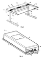
- Fig. 3 illustrates a height-adjustable table 1 shown in perspective, where the table top 2 is depicted as transparent.
- the carrying frame 3 on which the table top 2 is mounted comprises two parallel longitudinal members 9 and two parallel cross members 10.
- the two lifting columns 4 are here interconnected by means of an architrave 11 in order to increase the stability of the height-adjustable table 1. It is desired to mount the motor housing 6 of the lifting columns and the control box 12 within the dimensions, i.e. length, width and height, given by these longitudinal members 9 and cross members 10. In order to keep within these dimensions, the distance between the two longitudinal members 9 is utilized such that the clearance between the control box 12 and the two longitudinal members 9 exactly renders the mounting of the control box 12 possible.
- the control box 12 comprises a box-shaped rectangular housing of plastic having an upper side 13 and an underside 14 and a wall consisting of two longitudinal parallel side walls 15, 16 and two oppositely located ends, known as connection sides 17,18.
- the two connection sides 17,18 of the control box 12 faces towards the right side 2c and left side 2d of the table top respectively and comprise a mains plug 19 for mains, two low-voltage plugs 20 for the lifting columns 4 and two modular plugs 21 for e.g. the control panel 22 and/or network.
- These plugs 19,20,21 are arranged so that the mains plug 19 is placed on one connection side 17 (see figure 5 ) of the control box 12, and the low-voltage plugs 20 and the modular plugs 21 are located on the other connection side 18 (see figure 4 ) of the control box 12.
- mains voltage is kept separate from low-voltage also within the control box, which is of great significance both practically and in terms of safety.
- the low-voltage plugs 20 may e.g. be of the Mini-fit type from the make Molex, or be of the type: Mini DIN, Power DIN or Jack.
- the low-voltage plugs may instead be constituted by the mains plug or be of a type intended for mains voltage.
- the modular plugs 21 may also be of the type and/or be known as modular bushings, Bell plugs, Bell bushings, modular crimp plugs and modular crimp bushings.
- the lifting columns 4 are placed at each side of the control box 12. Since the low-voltage plugs 20 for the linear actuators only are located on the connection side 18 of the control box 12 the cable from the linear actuator 4 facing towards the connection side 17 comprising the mains plug 19 should be led over to the connection side 18 comprising the low-voltage plugs 20 for the linear actuators 4 and modular plugs 21 for the control panel 22, without the dimensions given by the longitudinal members 9 and the cross members 10 being exceeded. Depending on the relative location of the control panel 22 and the orientation of the connection sides 17, 18 of the control box 12, it may also occur that also the cable between the control panel 22 and the modular plug 21 should be guided past the control box 12. This should also be done in such a manner that the dimensions given by the longitudinal members 9 are not exceeded.
- Figs. 4 and 5 show a perspective view of the control box 12.
- Fig. 4 shows the control box 12 with the upper side 13 facing up.
- the connection side 18 is furnished with two low-voltage plugs 20 for the linear actuators and two modular plugs 21, of which one may be used for the control panel 22.
- Fig. 5 shows the control box 12 with the underside 14 facing up and with the connection side 17 comprising the mains plug 19.
- the underside 14 further comprises two cable runs 23,24 in which e.g. the cable for a lifting column 4 may be guided between the two connection sides 17,18.
- the cable for a lifting column 4 also comprises supply- as well as signal cables.
- Fig. 6 shows the control box 12 where the upper side 13 of the housing (see fig. 4 ) has been cut away.
- the control box 12 comprises a toroidal transformer 25, a control device 26, the mains plug 19, the two low-voltage plugs 20 and the two modular plugs 21.
- These main components are located within the housing of the control box, which consists of an upper part in the shape of an open box containing the connection sides 17,18, the upper side 13, the side walls 15,16, and a bottom part comprising the underside 14.
- the bottom part is mounted on the open box by means of screws, as a plurality of screw towers 27 are integrated in the side walls 15,16 and the connection sides 17,18.
- the dimensions of the toroidal transformer 25 results in there being only minimal clearance between the internal side of the side walls 15,16 and the toroidal transformer 25, and between the toroidal transformer 25 and the internal side of the underside 14 and the upper side 13 (see fig.4 ) of the control box housing, respectively.
- the plurality of screw towers 27 is integrated in the respective side walls 15,16 and connection sides 17,18.
- FIG. 7 shows a perspective view of the control box 12, where the entire underside 14 and the connection side 18 is visible.
- a piece of cable 28 is shown as guided into the cable run 23 (see fig. 5 ), which is constructed as a groove, which is open towards the free space.
- the cable run From the connection side 18 the cable run has a straight course roughly parallel to the longitudinal axis of the control box and further a straight course towards the other connection side 17.
- the two straight courses of the cable run are connected to a curved course, running around the toroidal transformer and towards the side walls 15,16 as the course extends between the two screw towers (see fig. 6 ).
- the winding course of the cable runs 23,24 functions as strain relief for the inserted cables 28.
- the cable runs 23,24 further comprise a plurality of fixation elements 29 (not all are marked with reference numerals, see also fig. 5 ) in the shape of short flap, which from the side walls of the cable run 23,24 extends into its hollow.
- the fixation elements 29 primarily ensures a retaining of the inserted cable 28, but the fixation elements 29 also contribute to the pull relief of the inserted cable 28.
- FIGS 8 and 9 show another embodiment of the control box 12, where the upper side 13 has another design.
- control box 12 When the control box 12 is mounted to the underside of the tabletop 2, this will further function as fixture for the cables guided in the cable runs 23,24, as the cables are located between the control box 12 and the underside of the table top 2.
- control box 12 may comprise either a higher or lower number or more or fewer types of plugs.
- the underside 14 of the control box 12 may further comprise just one or more than two cable runs 23,24.
- the cable runs 23,24 may be constructed on the upper side 13 or the side walls 15,16 of the control box.
- the entire or part of the course of the cable run 23,24 may be fully or partially closed. This is achieved in that the edge or edges between the wall of the cable run 23,24 and the underside 14 of the control box comprise one or more hinged hatches or flaps.
- the opening of the cable run 23,24 may be partially closed by means of a rubber membrane having a cut slot through which the cable 28 can be pushed.
- the control box 12 may comprise a pull relief 30 as shown in fig. 5 .
- the pull relief 30 is designed as a cable run or a U-shaped groove in the underside 14 of the control box, which is open towards the free space.
- the groove of the pull relief 30 has two open outlets towards the connections side 17.
- the pull relief 30 may advantageous be used for placing the mains cable, which should be connected to the mains plug 19.
- the mains cable cannot unintentionally be pulled out of the mains plug 19.
- Figure 10 shows a schematic view of an electric actuator system comprising a control box 12 supplied with a mains voltage 31 through the mains cable 32.
- the control box 12 is of the type described above and one plug on the mains cable is thus connected to the mains plug 19 (see figs. 5 and 8 ).
- the electric actuator system further comprises one or more linear actuators 4,33, connected to the control box 12 by means of one or more motor cables 34.
- the electric actuator system comprises one or more operating devices 22,35,36 connected to the control box through one or more control cables 37.
- the schematic view only depicts one motor cable 34 and control cable 37.
- the electric actuator system may be configured with one or more linear actuators 4,33 of the same or of different types.
- figure 10 shows a lifting column 4 with a built-in linear actuator (see also figs. 1 and 3 ).
- the electric actuator system may be configured with one or more control devices 22,35,36 of the same or of different types.
- control box 12 having a rectangular box-shaped housing is described but the invention may also be used in connection with a housing having another geometric shape, e.g. octagonal or circular.
Landscapes
- Tables And Desks Characterized By Structural Shape (AREA)
Description
- The present invention relates to an electric actuator system for adjustable articles of furniture, preferably height-adjustable tables. The invention further relates to a control box and an adjustable article of furniture.
- For explanation, the invention derives from a height-adjustable table having a table top mounted on an under frame. Said under frame comprises a carrying frame for the table top and linear actuators in the shape of lifting columns, appearing as table legs, being equipped with a foot at its lower end. The carrying frame is mounted to the upper end of the linear actuators. More precisely reference is made to the type of table shown in
fig. 3 ofEP 2 160 958 - In terms of logistics and shipping the tables appear as unassembled, so that they take up as little space as possible and may be shipped as a flat package. The tables are typically not assembled until they reach the end-user, where the supplier will mount the feet onto the linear actuators, the carrying frame on top of the actuators and thereafter the table top. Lastly, the cables for the linear actuators, the control box and the control panel are mounted and placed where it in the present case seems expedient. The control box is thus mounted at a random place under the table top and the cable run will thus be placed accordingly. The cables are unprotected and randomly guided under the table top and excess lengths of the cable are just rolled up and more or less randomly clipped and hung under the table top. In order to keep track of the cable run and avoid what is popularly known as "cable jumble", a cable tray intended for that purpose may be mounted under the table. As the cable tray will appear as part of the appearance of the table it is necessary to design the cable tray such that it fits the general appearance of the table. In a marked where the price for tables is under pressure, this is an unacceptably expensive solution.
- In respect to height-adjustable desks or work tables it is desired to have the lifting columns, control box and operating device placed such that the free space for the user under the table top is taken into consideration as much as possible. Furthermore, the industrial inspectorate has standards and directions, which determines and recommends a given size of the free space under the table. In terms of design it is further desired that especially the motor housing of the lifting columns and the control box are not noticeably visible. This further applies to the cables between the control box and the lifting columns and control panels respectively. In order to meet these requirements the idea of mounting the control box and various cables within the dimensions given by the two longitudinal members of the carrying frame mounted under the table top has emerged. The distance between the two longitudinal members is, as already mentioned, given by the width of the motor housing. In order to be able to fit the control box in, it is thus necessary to reduce the outer dimensions of the control box. As the power supply of the control box is build up around a toroidal transformer, the need to reduce the measurements of the control box is a challenge in terms of space. This is due to the fact that the dimensions of the toroidal transformer cannot immediately be changed. Due to the operational reliability and service life of the control box it is however desired to maintain the toroidal transformer. This is e.g. owing to the fact that actuators in certain situations may draw close to 15 ampere, which a toroidal transformer will be able to supply. With an optimization of the toroidal transformer it has however been accomplished to reduce its dimensions somewhat, but it is necessary to place the toroidal transformer immediately up against the internal sides of the control box housing. Thus, the width of the control box is reduced so that it accurately may be fitted between the two longitudinal members.
- In order to simplify the cable connection to the control box and minimize the risk of erroneous connection, it is further expedient that the mains plug of the control box is kept separate from the low-voltage plugs to the lifting columns and modular plugs for the control panel. It is thus expedient that these plugs are placed on opposite ends of the control box. Compared to the given installation dimensions, this positioning of the control box plugs results therein that the cable between at least one of the lifting columns and the control box cannot be guided within the outlined installation dimensions. Despite the fact that this cable may be guided outside of the dimensions given by the longitudinal members this is not a desired solution.
- The invention relates to the problem in relation to a height-adjustable table of guiding at least one cable from one side of the control box to the opposite side without exceeding the installation dimensions given by the longitudinal members under the table top of the height-adjustable table.
- The purpose of the invention is to provide a control box, which takes this into account and does not change the outer dimensions of the control box, such that the control box may be mounted within the dimensions, given by the longitudinal members.
- This is achieved according to the invention with an electric actuator system as described in
claim 1. By providing an electric actuator system comprising a cable run located on the outer side of the control box it is possible, even with a toroidal transformer within the dimensions given by the longitudinal members, to guide cables between the two ends with plugs of the control box. Thus the user achieves the desired free space under the table and the height-adjustable table further appears as having the desired expression as regards design. Further, the possibility for unambiguous separation of the mains plug and the other plugs of the control box including low-voltage plugs and modular plugs is retained. The control box typically contains a printed circuit board, onto which electric components are mounted, which results therein that the printed circuit board should be mounted a short distance from the inside of the housing. The groove-shaped cable run is expediently designed such that it extends into the housing, i.e. such that does not extend outside the outer perimeter of the housing. In this embodiment the groove-shaped cable run is practically placed under the printed circuit board and may further be used such that the printed circuit board rests on the back of the cable run. When the groove-shaped cable run extends into the housing, it will also function as cable fixation when the control box with the side furnished with the cable run is mounted against a firm surface. - In an embodiment the cable run is located at the underside of the control box. This makes it possible to hide cables guided between the plugs of the control box as much as possible, as the underside of the control box is mounted to the underside of the table top of the height-adjustable table. A consequence of the cable run being located at the underside of the control box is of course that the cable must be mounted in the cable run before the control box can be mounted between the two longitudinal members under the table top.
- In an embodiment of the invention the cable run is guided around the area of the toroidal transformer. Thus, it is ensured that the cable run does not take up space, which could have been used by the toroidal transformer. Thus, an increase of the dimensions of the control box, which would collide with the installation dimensions given by the longitudinal members, is avoided.
- In an embodiment the cable run has a winding course. This course functions as a strain relief for the cable mounted in the cable run.
- In a further embodiment there are more cable runs for various cable thicknesses. Besides from cable for an actuator this makes it possible to run cables for the control panel depending on in which side of the table this control panel should be mounted. It will further be possible to run the mains cable along the control box also depending on whether it is most convenient to run the cable from one or the other side of the table.
- In an embodiment the cable run comprises at least one fixation element. This fixation element makes it easy to retain the cable mounted in the cable run despite the fact that the cable run faces downwards. Furthermore, the fixation element contributes to protecting the mounted cable against pull.
- The invention further relates to a control box for an electric actuator system comprising a box-shaped housing having an outer wall with a mains plug for supplying the control box with mains voltage and a low-voltage plug located opposite of this for connecting a linear actuator and at least one modular plug for connecting a control panel, and where the control box further comprises a power supply for connection to mains, which is characteristic in that the external side of the control box housing comprises at least one cable run in the shape of a groove, which is open towards the free space such that the cable may be guided along the control box.
- By realization of the invention it is understood that the invention is not limited to control boxes having a power supply based on a toroidal transformer. The invention may also be used in connection with a switch mode power supply, where a need for a secure guiding of cables from one end of the control box to the other likewise may arise.
- The invention further relates to an electrically adjustable article of furniture, preferably a height-adjustable table furnished with an actuator system according to one of the claims 1-6. By realization of the invention it is further understood that the invention is not limited to use in connection with height-adjustable tables. The invention may also be used in connection with height-adjustable beds and chairs. In an embodiment of the adjustable article of furniture, this comprises an element having a plane surface onto which the control box may be mounted. An example of a hospital bed having a flat plane middle section onto which the control box may be mounted is shown in
Fig. 1 ofEP 0 498 111 A2 - Further characteristics of the invention will be explained in connection with the following description of an embodiment for the electric actuator system according to the invention under reference to the accompanying drawing, in which:
-
Fig. 1 , shows a perspective view of a height-adjustable table, -
fig. 2 , shows a height-adjustable table shown from the side, -
fig. 3 , shows a perspective view of a rough sketch of a height-adjustable table, -
fig. 4 , shows a perspective view of a control box shown from above, -
fig. 5 , shows a perspective view of a control box shown from below, -
fig. 6 , shows an open control box seen from above, -
fig. 7 , shows a perspective view of a control box shown from below, having a cable guided in the cable run, -
fig. 8 shows another embodiment of a control box with an upper side, -
fig. 9 , shows another embodiment of a control box with an upper side, and -
fig. 10 , shows an electric actuator system. -
Fig. 1 shows a perspective view of a height-adjustable table 1 comprising atable top 2, having afront side 2a, arear side 2b, aright side 2c and aleft side 2d. At the right 2c andleft side 2d respectively a linear actuator in the form of alifting column 4 e.g. of the type described inWO2004/100632 A1 Linak A/S is mounted in a carrying frame 3 (seefig. 3 ) onto which thetable top 2 is mounted. The other end of each liftingcolumn 4 comprises afoot 7 on which the height-adjustable table 1 stands. Thelifting columns 4 comprises a motor housing 6 (seefigure 3 ) and two mutually telescopically arranged profiles. Oneprofile 5 is stationary fixed to thefoot 7 and the other profile may be displaced telescopically in and out of thestationary profile 5. The displaceable profile is moved by means of an electric motor, which through a gear drives a spindle. The spindle is furnished with a spindle nut secured to the telescopically movable member. The displacement of thetable top 2 it thus determined by the movable profile. -
Fig. 2 shows, shown from the side, thefree space 8 which the user of the height-adjustable table 1 has under thetable top 2 when the table top is in its lowest position. -
Fig. 3 illustrates a height-adjustable table 1 shown in perspective, where thetable top 2 is depicted as transparent. The carryingframe 3 on which thetable top 2 is mounted comprises two parallel longitudinal members 9 and twoparallel cross members 10. The twolifting columns 4 are here interconnected by means of anarchitrave 11 in order to increase the stability of the height-adjustable table 1. It is desired to mount themotor housing 6 of the lifting columns and thecontrol box 12 within the dimensions, i.e. length, width and height, given by these longitudinal members 9 andcross members 10. In order to keep within these dimensions, the distance between the two longitudinal members 9 is utilized such that the clearance between thecontrol box 12 and the two longitudinal members 9 exactly renders the mounting of thecontrol box 12 possible. - In the following the control box will be described under reference to
figures 4-7 . Thecontrol box 12 comprises a box-shaped rectangular housing of plastic having anupper side 13 and anunderside 14 and a wall consisting of two longitudinalparallel side walls - In the mounted state of the
control box 12 the twoconnection sides control box 12 faces towards theright side 2c andleft side 2d of the table top respectively and comprise a mains plug 19 for mains, two low-voltage plugs 20 for thelifting columns 4 and twomodular plugs 21 for e.g. thecontrol panel 22 and/or network. These plugs 19,20,21 are arranged so that the mains plug 19 is placed on one connection side 17 (seefigure 5 ) of thecontrol box 12, and the low-voltage plugs 20 and themodular plugs 21 are located on the other connection side 18 (seefigure 4 ) of thecontrol box 12. Thus, mains voltage is kept separate from low-voltage also within the control box, which is of great significance both practically and in terms of safety. The low-voltage plugs 20 may e.g. be of the Mini-fit type from the make Molex, or be of the type: Mini DIN, Power DIN or Jack. The low-voltage plugs may instead be constituted by the mains plug or be of a type intended for mains voltage. The modular plugs 21 may also be of the type and/or be known as modular bushings, Bell plugs, Bell bushings, modular crimp plugs and modular crimp bushings. - As it appears from
Figures 1 and3 thelifting columns 4 are placed at each side of thecontrol box 12. Since the low-voltage plugs 20 for the linear actuators only are located on theconnection side 18 of thecontrol box 12 the cable from thelinear actuator 4 facing towards theconnection side 17 comprising the mains plug 19 should be led over to theconnection side 18 comprising the low-voltage plugs 20 for thelinear actuators 4 andmodular plugs 21 for thecontrol panel 22, without the dimensions given by the longitudinal members 9 and thecross members 10 being exceeded. Depending on the relative location of thecontrol panel 22 and the orientation of the connection sides 17, 18 of thecontrol box 12, it may also occur that also the cable between thecontrol panel 22 and themodular plug 21 should be guided past thecontrol box 12. This should also be done in such a manner that the dimensions given by the longitudinal members 9 are not exceeded. -
Figs. 4 and5 show a perspective view of thecontrol box 12.Fig. 4 shows thecontrol box 12 with theupper side 13 facing up. Theconnection side 18 is furnished with two low-voltage plugs 20 for the linear actuators and twomodular plugs 21, of which one may be used for thecontrol panel 22.Fig. 5 shows thecontrol box 12 with theunderside 14 facing up and with theconnection side 17 comprising the mains plug 19. Theunderside 14 further comprises two cable runs 23,24 in which e.g. the cable for alifting column 4 may be guided between the twoconnection sides figure 3 ) are not exceeded. The cable for alifting column 4 also comprises supply- as well as signal cables. -
Fig. 6 shows thecontrol box 12 where theupper side 13 of the housing (seefig. 4 ) has been cut away. Thecontrol box 12 comprises atoroidal transformer 25, acontrol device 26, the mains plug 19, the two low-voltage plugs 20 and the twomodular plugs 21. These main components are located within the housing of the control box, which consists of an upper part in the shape of an open box containing the connection sides 17,18, theupper side 13, theside walls underside 14. The bottom part is mounted on the open box by means of screws, as a plurality of screw towers 27 are integrated in theside walls toroidal transformer 25 results in there being only minimal clearance between the internal side of theside walls toroidal transformer 25, and between thetoroidal transformer 25 and the internal side of theunderside 14 and the upper side 13 (seefig.4 ) of the control box housing, respectively. The plurality of screw towers 27 is integrated in therespective side walls -
Figure 7 , shows a perspective view of thecontrol box 12, where theentire underside 14 and theconnection side 18 is visible. A piece ofcable 28 is shown as guided into the cable run 23 (seefig. 5 ), which is constructed as a groove, which is open towards the free space. From theconnection side 18 the cable run has a straight course roughly parallel to the longitudinal axis of the control box and further a straight course towards theother connection side 17. The two straight courses of the cable run are connected to a curved course, running around the toroidal transformer and towards theside walls fig. 6 ). The winding course of the cable runs 23,24 functions as strain relief for the insertedcables 28. The cable runs 23,24 further comprise a plurality of fixation elements 29 (not all are marked with reference numerals, see alsofig. 5 ) in the shape of short flap, which from the side walls of thecable run fixation elements 29 primarily ensures a retaining of the insertedcable 28, but thefixation elements 29 also contribute to the pull relief of the insertedcable 28. -
Figures 8 and9 show another embodiment of thecontrol box 12, where theupper side 13 has another design. - When the
control box 12 is mounted to the underside of thetabletop 2, this will further function as fixture for the cables guided in the cable runs 23,24, as the cables are located between thecontrol box 12 and the underside of thetable top 2. - In an alternative embodiment the
control box 12 may comprise either a higher or lower number or more or fewer types of plugs. Theunderside 14 of thecontrol box 12 may further comprise just one or more than two cable runs 23,24. In yet another embodiment the cable runs 23,24 may be constructed on theupper side 13 or theside walls - In an alternative embodiment the entire or part of the course of the
cable run cable run underside 14 of the control box comprise one or more hinged hatches or flaps. Alternatively, the opening of thecable run cable 28 can be pushed. In another alternative embodiment thecontrol box 12 may comprise apull relief 30 as shown infig. 5 . Thepull relief 30 is designed as a cable run or a U-shaped groove in theunderside 14 of the control box, which is open towards the free space. The groove of thepull relief 30 has two open outlets towards theconnections side 17. Thus, thepull relief 30 may advantageous be used for placing the mains cable, which should be connected to the mains plug 19. Thus, the mains cable cannot unintentionally be pulled out of the mains plug 19. -
Figure 10 shows a schematic view of an electric actuator system comprising acontrol box 12 supplied with amains voltage 31 through themains cable 32. Thecontrol box 12 is of the type described above and one plug on the mains cable is thus connected to the mains plug 19 (seefigs. 5 and8 ). The electric actuator system further comprises one or morelinear actuators control box 12 by means of one ormore motor cables 34. Furthermore, the electric actuator system comprises one ormore operating devices more control cables 37. For the sake of clarity, the schematic view only depicts onemotor cable 34 andcontrol cable 37. It is noted that the electric actuator system may be configured with one or morelinear actuators figure 10 shows alifting column 4 with a built-in linear actuator (see alsofigs. 1 and3 ). It is further noted that the electric actuator system may be configured with one ormore control devices - Here, a
control box 12 having a rectangular box-shaped housing is described but the invention may also be used in connection with a housing having another geometric shape, e.g. octagonal or circular.
Claims (15)
- Electric actuator system for adjustable articles of furniture, especially height-adjustable tables (1) comprising one or more linear actuators (4,33), a control box (12) and one or more operating devices (22,35,36), where the control box (12) comprises a control box housing (13,14,15,16,17,18) and a mains plug (19) located in the control box housing (13,14,15,16,17,18), where the control box housing (13,14,15,16,17,18) comprises two oppositely located connection sides (17,18) and where the electric actuator system comprises a mains cable (32) connected to the mains plug (19) supplying the control box (12) with mains voltage (31), and where the control box housing (13,14,15,16,17,18) comprises one or more plugs, preferably low voltage plugs (20) for connection of one or more linear actuators (4,33) and one or more plugs, preferably modular plugs (21) for connecting one or more operating devices (22,35,36), and where the control box (12) further comprises a power supply for connection to mains (31), and where the electric actuator system comprises one or more motor cables (34) for connecting one or more linear actuators (4,33) to one or more plugs (20), and where the electric actuator system comprises one or more control cables (37) for connecting one or more operating devices (22,35,36) to one or more plugs (21),
characterized in
that the control box (12) comprises one or more cable runs (23,24) for guiding a cable (28,34,37) between the two connections sides (17,18), and where the cable runs (23,24) are designed as an integral part of the outer side of the control box housing (13,14,15,16,17,18). - Electric actuator system according to claim 1, characterized in that the cable run (23,24) is designed as an open groove.
- Electric actuator system according to the claims 1-2, characterized in that the cable run (23,24) is located at the underside (14) of the housing.
- Electric actuator system according to claim 2, characterized in that the cable run (23,24) is entirely or partially covered.
- Electric actuator system according to one or more of the claims 1-4, character ized in that the mains plug (19) and one or more plugs (20) for connecting one or more actuators (4,33) are placed on each of the connection sides (17,18) of the control box (12).
- Electric actuator system according to one or more of the claims 1-5, character ized in that power supply of the control box comprises a toroidal transformer (25) and that the cable run (23,24) is guided around this.
- Electric actuator system according to one or more of the claims 1-6, character ized in that the cable run (23,24) has a winding course.
- Electric actuator system according to one or more of the claims 1-7, character ized in that the cable run (23,24) is adapted to a given cable thickness.
- Electric actuator system according to one or more of the claims 1-8, character ized in that the cable run (23,24) comprises at least one fixation element (29) for a cable (28,32,34,37).
- Control box (12) for an electric actuator system comprising a housing (13,14,15,16,17,18) where the control box housing (13,14,15,16,17,18) comprises two oppositely located connection sides (17,18), a mains plug (19) for supplying the control box (12) with mains voltage, one or more plugs, preferably low voltage plugs (20) for connection of one or more linear actuators and one or more plugs, preferably modular plugs (21) for connecting one or more operating devices (22), characterized in that the control box comprises one or more cable runs (23,24) for guiding a cable (28,34,37) between the two connections sides (17,18), and where the cable runs (23,24) are designed as an integral part of the outer side of the control box housing (13,14,15,16,17,18).
- A control box for an electric actuator system according to claim 10 comprising a power supply for connection to mains voltage.
- Electrically adjustable article of furniture comprising an electric actuator system according to one of the claims 1-8.
- Electrically adjustable article of furniture according to claim 11, where the electrically adjustable article of furniture is a height-adjustable table (1).
- Electrically adjustable article of furniture according to claim 11, comprising an element having a plane surface on which the control box (12) is mounted.
- Electrically adjustable article of furniture according to claim 13, characteri zed in that the height-adjustable table comprises a table top (2) where the control box (12) is mounted to the underside of the table top (2).
Applications Claiming Priority (1)
| Application Number | Priority Date | Filing Date | Title |
|---|---|---|---|
| DKPA201001032 | 2010-11-13 |
Publications (2)
| Publication Number | Publication Date |
|---|---|
| EP2452589A1 EP2452589A1 (en) | 2012-05-16 |
| EP2452589B1 true EP2452589B1 (en) | 2014-06-18 |
Family
ID=45418295
Family Applications (1)
| Application Number | Title | Priority Date | Filing Date |
|---|---|---|---|
| EP11008964.6A Active EP2452589B1 (en) | 2010-11-13 | 2011-11-10 | Electrical actuator system |
Country Status (3)
| Country | Link |
|---|---|
| EP (1) | EP2452589B1 (en) |
| DE (1) | DE202011110450U1 (en) |
| DK (1) | DK2452589T3 (en) |
Cited By (2)
| Publication number | Priority date | Publication date | Assignee | Title |
|---|---|---|---|---|
| DE202016106541U1 (en) | 2016-11-23 | 2016-12-15 | Oelschläger Metalltechnik GmbH | Control box with cable strain relief |
| WO2022007692A1 (en) * | 2020-07-08 | 2022-01-13 | 浙江捷昌线性驱动科技股份有限公司 | Outer-side wiring lifting table controller and lifting table frame |
Families Citing this family (2)
| Publication number | Priority date | Publication date | Assignee | Title |
|---|---|---|---|---|
| DE202014003943U1 (en) | 2013-05-10 | 2014-08-21 | Linak A/S | Electric drive system |
| DE102014111626B4 (en) * | 2014-08-14 | 2016-06-16 | Logicdata Electronic & Software Entwicklungs Gmbh | Electrically adjustable table system |
Family Cites Families (5)
| Publication number | Priority date | Publication date | Assignee | Title |
|---|---|---|---|---|
| GB2252495B (en) | 1991-02-06 | 1994-12-14 | Nesbit Evans & Co Ltd | "Adjustable beds" |
| US7049728B2 (en) * | 2001-12-13 | 2006-05-23 | Linak A/S | Adjustable construction preferably an article of furniture and a squeeze protection and a drive unit thereto |
| JP2007524041A (en) | 2003-05-06 | 2007-08-23 | リナック エー/エス | Actuator |
| DE102005037363A1 (en) * | 2005-08-08 | 2007-02-15 | BSH Bosch und Siemens Hausgeräte GmbH | Electrical device with a cable receiving device |
| US8752488B2 (en) | 2008-09-08 | 2014-06-17 | Linak A/S | Height adjustable table |
-
2011
- 2011-11-10 DK DK11008964.6T patent/DK2452589T3/en active
- 2011-11-10 DE DE202011110450.1U patent/DE202011110450U1/en not_active Expired - Lifetime
- 2011-11-10 EP EP11008964.6A patent/EP2452589B1/en active Active
Cited By (3)
| Publication number | Priority date | Publication date | Assignee | Title |
|---|---|---|---|---|
| DE202016106541U1 (en) | 2016-11-23 | 2016-12-15 | Oelschläger Metalltechnik GmbH | Control box with cable strain relief |
| WO2018095462A1 (en) | 2016-11-23 | 2018-05-31 | Oelschläger Metalltechnik GmbH | Control box with cable-strain relief |
| WO2022007692A1 (en) * | 2020-07-08 | 2022-01-13 | 浙江捷昌线性驱动科技股份有限公司 | Outer-side wiring lifting table controller and lifting table frame |
Also Published As
| Publication number | Publication date |
|---|---|
| DK2452589T3 (en) | 2014-07-21 |
| EP2452589A1 (en) | 2012-05-16 |
| DE202011110450U1 (en) | 2014-03-14 |
Similar Documents
| Publication | Publication Date | Title |
|---|---|---|
| US9703278B2 (en) | Electrical actuator system for adjustable furniture with control box having ports in opposing walls | |
| US6360675B1 (en) | Adjustable table cord storage assembly | |
| EP2452589A1 (en) | Electrical actuator system | |
| CN110934421A (en) | Height adjustable table or platform | |
| EP3440958B1 (en) | Motorized adjustable height table | |
| EP2823731B1 (en) | Vertically adjustable table construction | |
| WO2015180724A1 (en) | Height-adjustable supporting frame | |
| US9516772B2 (en) | Table-mounted cord retractor | |
| US9854903B1 (en) | Table with retractable power cables | |
| US8233283B2 (en) | Power supply device | |
| WO2014185938A1 (en) | Counterbalancing assembly for folding furniture | |
| US20110133618A1 (en) | Housing for at least partially accommodating a furniture fitting | |
| CN105342133A (en) | Electric studying elevating table | |
| CN206004171U (en) | The Based Intelligent Control distribution box that a kind of easy care is adjusted | |
| JP6598053B2 (en) | Fixture unit with top plate | |
| EP1947981B1 (en) | An article of furniture, in particular a sitting/standing table | |
| CN204968287U (en) | Novel control cabinet | |
| EP2140780B1 (en) | Table | |
| KR200419231Y1 (en) | Boxed Multi-tap | |
| EP0910881A1 (en) | Device for electrically powering a plurality of user items provided with their own electrical feed and data transfer cables, to at least partially contain theses cables during said feed | |
| PL198225B1 (en) | Attachment to a power distribution cabinet | |
| JP2018126319A (en) | Top plate elevation type furniture | |
| CN217959335U (en) | Combined office table | |
| JP5593151B2 (en) | Desk equipment | |
| HK1001084A1 (en) | Furniture box provided with an electrical power supply arrangement |
Legal Events
| Date | Code | Title | Description |
|---|---|---|---|
| REG | Reference to a national code |
Ref country code: DE Ref legal event code: R138 Ref document number: 602011007686 Country of ref document: DE Free format text: GERMAN DOCUMENT NUMBER IS 602011007686 Ref country code: DE Ref legal event code: R138 Ref document number: 202011110450 Country of ref document: DE Free format text: GERMAN DOCUMENT NUMBER IS 602011007686 |
|
| PUAI | Public reference made under article 153(3) epc to a published international application that has entered the european phase |
Free format text: ORIGINAL CODE: 0009012 |
|
| AK | Designated contracting states |
Kind code of ref document: A1 Designated state(s): AL AT BE BG CH CY CZ DE DK EE ES FI FR GB GR HR HU IE IS IT LI LT LU LV MC MK MT NL NO PL PT RO RS SE SI SK SM TR |
|
| AX | Request for extension of the european patent |
Extension state: BA ME |
|
| 17P | Request for examination filed |
Effective date: 20121108 |
|
| GRAP | Despatch of communication of intention to grant a patent |
Free format text: ORIGINAL CODE: EPIDOSNIGR1 |
|
| INTG | Intention to grant announced |
Effective date: 20140213 |
|
| GRAS | Grant fee paid |
Free format text: ORIGINAL CODE: EPIDOSNIGR3 |
|
| GRAA | (expected) grant |
Free format text: ORIGINAL CODE: 0009210 |
|
| AK | Designated contracting states |
Kind code of ref document: B1 Designated state(s): AL AT BE BG CH CY CZ DE DK EE ES FI FR GB GR HR HU IE IS IT LI LT LU LV MC MK MT NL NO PL PT RO RS SE SI SK SM TR |
|
| REG | Reference to a national code |
Ref country code: GB Ref legal event code: FG4D |
|
| REG | Reference to a national code |
Ref country code: CH Ref legal event code: NV Representative=s name: TROESCH SCHEIDEGGER WERNER AG, CH Ref country code: CH Ref legal event code: EP |
|
| REG | Reference to a national code |
Ref country code: AT Ref legal event code: REF Ref document number: 672831 Country of ref document: AT Kind code of ref document: T Effective date: 20140715 |
|
| REG | Reference to a national code |
Ref country code: IE Ref legal event code: FG4D |
|
| REG | Reference to a national code |
Ref country code: DK Ref legal event code: T3 Effective date: 20140716 |
|
| REG | Reference to a national code |
Ref country code: DE Ref legal event code: R096 Ref document number: 602011007686 Country of ref document: DE Effective date: 20140731 |
|
| REG | Reference to a national code |
Ref country code: SE Ref legal event code: TRGR |
|
| PG25 | Lapsed in a contracting state [announced via postgrant information from national office to epo] |
Ref country code: FI Free format text: LAPSE BECAUSE OF FAILURE TO SUBMIT A TRANSLATION OF THE DESCRIPTION OR TO PAY THE FEE WITHIN THE PRESCRIBED TIME-LIMIT Effective date: 20140618 Ref country code: LT Free format text: LAPSE BECAUSE OF FAILURE TO SUBMIT A TRANSLATION OF THE DESCRIPTION OR TO PAY THE FEE WITHIN THE PRESCRIBED TIME-LIMIT Effective date: 20140618 Ref country code: CY Free format text: LAPSE BECAUSE OF FAILURE TO SUBMIT A TRANSLATION OF THE DESCRIPTION OR TO PAY THE FEE WITHIN THE PRESCRIBED TIME-LIMIT Effective date: 20140618 Ref country code: NO Free format text: LAPSE BECAUSE OF FAILURE TO SUBMIT A TRANSLATION OF THE DESCRIPTION OR TO PAY THE FEE WITHIN THE PRESCRIBED TIME-LIMIT Effective date: 20140918 Ref country code: GR Free format text: LAPSE BECAUSE OF FAILURE TO SUBMIT A TRANSLATION OF THE DESCRIPTION OR TO PAY THE FEE WITHIN THE PRESCRIBED TIME-LIMIT Effective date: 20140919 |
|
| REG | Reference to a national code |
Ref country code: NL Ref legal event code: VDEP Effective date: 20140618 |
|
| REG | Reference to a national code |
Ref country code: AT Ref legal event code: MK05 Ref document number: 672831 Country of ref document: AT Kind code of ref document: T Effective date: 20140618 |
|
| REG | Reference to a national code |
Ref country code: LT Ref legal event code: MG4D |
|
| PG25 | Lapsed in a contracting state [announced via postgrant information from national office to epo] |
Ref country code: LV Free format text: LAPSE BECAUSE OF FAILURE TO SUBMIT A TRANSLATION OF THE DESCRIPTION OR TO PAY THE FEE WITHIN THE PRESCRIBED TIME-LIMIT Effective date: 20140618 Ref country code: RS Free format text: LAPSE BECAUSE OF FAILURE TO SUBMIT A TRANSLATION OF THE DESCRIPTION OR TO PAY THE FEE WITHIN THE PRESCRIBED TIME-LIMIT Effective date: 20140618 Ref country code: HR Free format text: LAPSE BECAUSE OF FAILURE TO SUBMIT A TRANSLATION OF THE DESCRIPTION OR TO PAY THE FEE WITHIN THE PRESCRIBED TIME-LIMIT Effective date: 20140618 |
|
| PG25 | Lapsed in a contracting state [announced via postgrant information from national office to epo] |
Ref country code: RO Free format text: LAPSE BECAUSE OF FAILURE TO SUBMIT A TRANSLATION OF THE DESCRIPTION OR TO PAY THE FEE WITHIN THE PRESCRIBED TIME-LIMIT Effective date: 20140618 Ref country code: CZ Free format text: LAPSE BECAUSE OF FAILURE TO SUBMIT A TRANSLATION OF THE DESCRIPTION OR TO PAY THE FEE WITHIN THE PRESCRIBED TIME-LIMIT Effective date: 20140618 Ref country code: EE Free format text: LAPSE BECAUSE OF FAILURE TO SUBMIT A TRANSLATION OF THE DESCRIPTION OR TO PAY THE FEE WITHIN THE PRESCRIBED TIME-LIMIT Effective date: 20140618 Ref country code: PT Free format text: LAPSE BECAUSE OF FAILURE TO SUBMIT A TRANSLATION OF THE DESCRIPTION OR TO PAY THE FEE WITHIN THE PRESCRIBED TIME-LIMIT Effective date: 20141020 Ref country code: SK Free format text: LAPSE BECAUSE OF FAILURE TO SUBMIT A TRANSLATION OF THE DESCRIPTION OR TO PAY THE FEE WITHIN THE PRESCRIBED TIME-LIMIT Effective date: 20140618 Ref country code: ES Free format text: LAPSE BECAUSE OF FAILURE TO SUBMIT A TRANSLATION OF THE DESCRIPTION OR TO PAY THE FEE WITHIN THE PRESCRIBED TIME-LIMIT Effective date: 20140618 |
|
| PG25 | Lapsed in a contracting state [announced via postgrant information from national office to epo] |
Ref country code: PL Free format text: LAPSE BECAUSE OF FAILURE TO SUBMIT A TRANSLATION OF THE DESCRIPTION OR TO PAY THE FEE WITHIN THE PRESCRIBED TIME-LIMIT Effective date: 20140618 Ref country code: AT Free format text: LAPSE BECAUSE OF FAILURE TO SUBMIT A TRANSLATION OF THE DESCRIPTION OR TO PAY THE FEE WITHIN THE PRESCRIBED TIME-LIMIT Effective date: 20140618 Ref country code: NL Free format text: LAPSE BECAUSE OF FAILURE TO SUBMIT A TRANSLATION OF THE DESCRIPTION OR TO PAY THE FEE WITHIN THE PRESCRIBED TIME-LIMIT Effective date: 20140618 Ref country code: IS Free format text: LAPSE BECAUSE OF FAILURE TO SUBMIT A TRANSLATION OF THE DESCRIPTION OR TO PAY THE FEE WITHIN THE PRESCRIBED TIME-LIMIT Effective date: 20141018 |
|
| REG | Reference to a national code |
Ref country code: HU Ref legal event code: AG4A Ref document number: E021656 Country of ref document: HU |
|
| REG | Reference to a national code |
Ref country code: DE Ref legal event code: R097 Ref document number: 602011007686 Country of ref document: DE |
|
| PLBE | No opposition filed within time limit |
Free format text: ORIGINAL CODE: 0009261 |
|
| STAA | Information on the status of an ep patent application or granted ep patent |
Free format text: STATUS: NO OPPOSITION FILED WITHIN TIME LIMIT |
|
| PG25 | Lapsed in a contracting state [announced via postgrant information from national office to epo] |
Ref country code: IT Free format text: LAPSE BECAUSE OF FAILURE TO SUBMIT A TRANSLATION OF THE DESCRIPTION OR TO PAY THE FEE WITHIN THE PRESCRIBED TIME-LIMIT Effective date: 20140618 |
|
| 26N | No opposition filed |
Effective date: 20150319 |
|
| PG25 | Lapsed in a contracting state [announced via postgrant information from national office to epo] |
Ref country code: BE Free format text: LAPSE BECAUSE OF FAILURE TO SUBMIT A TRANSLATION OF THE DESCRIPTION OR TO PAY THE FEE WITHIN THE PRESCRIBED TIME-LIMIT Effective date: 20140618 Ref country code: LU Free format text: LAPSE BECAUSE OF FAILURE TO SUBMIT A TRANSLATION OF THE DESCRIPTION OR TO PAY THE FEE WITHIN THE PRESCRIBED TIME-LIMIT Effective date: 20141110 Ref country code: MC Free format text: LAPSE BECAUSE OF FAILURE TO SUBMIT A TRANSLATION OF THE DESCRIPTION OR TO PAY THE FEE WITHIN THE PRESCRIBED TIME-LIMIT Effective date: 20140618 |
|
| PG25 | Lapsed in a contracting state [announced via postgrant information from national office to epo] |
Ref country code: SI Free format text: LAPSE BECAUSE OF FAILURE TO SUBMIT A TRANSLATION OF THE DESCRIPTION OR TO PAY THE FEE WITHIN THE PRESCRIBED TIME-LIMIT Effective date: 20140618 |
|
| REG | Reference to a national code |
Ref country code: IE Ref legal event code: MM4A |
|
| REG | Reference to a national code |
Ref country code: FR Ref legal event code: ST Effective date: 20150731 |
|
| PG25 | Lapsed in a contracting state [announced via postgrant information from national office to epo] |
Ref country code: IE Free format text: LAPSE BECAUSE OF NON-PAYMENT OF DUE FEES Effective date: 20141110 |
|
| PG25 | Lapsed in a contracting state [announced via postgrant information from national office to epo] |
Ref country code: FR Free format text: LAPSE BECAUSE OF NON-PAYMENT OF DUE FEES Effective date: 20141201 |
|
| PG25 | Lapsed in a contracting state [announced via postgrant information from national office to epo] |
Ref country code: SM Free format text: LAPSE BECAUSE OF FAILURE TO SUBMIT A TRANSLATION OF THE DESCRIPTION OR TO PAY THE FEE WITHIN THE PRESCRIBED TIME-LIMIT Effective date: 20140618 |
|
| PG25 | Lapsed in a contracting state [announced via postgrant information from national office to epo] |
Ref country code: BG Free format text: LAPSE BECAUSE OF FAILURE TO SUBMIT A TRANSLATION OF THE DESCRIPTION OR TO PAY THE FEE WITHIN THE PRESCRIBED TIME-LIMIT Effective date: 20140618 |
|
| GBPC | Gb: european patent ceased through non-payment of renewal fee |
Effective date: 20151110 |
|
| PG25 | Lapsed in a contracting state [announced via postgrant information from national office to epo] |
Ref country code: MT Free format text: LAPSE BECAUSE OF FAILURE TO SUBMIT A TRANSLATION OF THE DESCRIPTION OR TO PAY THE FEE WITHIN THE PRESCRIBED TIME-LIMIT Effective date: 20140618 Ref country code: TR Free format text: LAPSE BECAUSE OF FAILURE TO SUBMIT A TRANSLATION OF THE DESCRIPTION OR TO PAY THE FEE WITHIN THE PRESCRIBED TIME-LIMIT Effective date: 20140618 |
|
| PG25 | Lapsed in a contracting state [announced via postgrant information from national office to epo] |
Ref country code: GB Free format text: LAPSE BECAUSE OF NON-PAYMENT OF DUE FEES Effective date: 20151110 |
|
| PG25 | Lapsed in a contracting state [announced via postgrant information from national office to epo] |
Ref country code: MK Free format text: LAPSE BECAUSE OF FAILURE TO SUBMIT A TRANSLATION OF THE DESCRIPTION OR TO PAY THE FEE WITHIN THE PRESCRIBED TIME-LIMIT Effective date: 20140618 |
|
| PG25 | Lapsed in a contracting state [announced via postgrant information from national office to epo] |
Ref country code: AL Free format text: LAPSE BECAUSE OF FAILURE TO SUBMIT A TRANSLATION OF THE DESCRIPTION OR TO PAY THE FEE WITHIN THE PRESCRIBED TIME-LIMIT Effective date: 20140618 |
|
| REG | Reference to a national code |
Ref country code: DE Ref legal event code: R082 Ref document number: 602011007686 Country of ref document: DE Representative=s name: KEIL & SCHAAFHAUSEN PATENTANWAELTE PARTGMBB, DE Ref country code: DE Ref legal event code: R082 Ref document number: 602011007686 Country of ref document: DE Representative=s name: KEIL & SCHAAFHAUSEN PATENT- UND RECHTSANWAELTE, DE |
|
| PGFP | Annual fee paid to national office [announced via postgrant information from national office to epo] |
Ref country code: AT Payment date: 20181022 Year of fee payment: 13 |
|
| PGFP | Annual fee paid to national office [announced via postgrant information from national office to epo] |
Ref country code: CH Payment date: 20181120 Year of fee payment: 8 |
|
| REG | Reference to a national code |
Ref country code: CH Ref legal event code: PL |
|
| PG25 | Lapsed in a contracting state [announced via postgrant information from national office to epo] |
Ref country code: LI Free format text: LAPSE BECAUSE OF NON-PAYMENT OF DUE FEES Effective date: 20191130 Ref country code: CH Free format text: LAPSE BECAUSE OF NON-PAYMENT OF DUE FEES Effective date: 20191130 |
|
| PG25 | Lapsed in a contracting state [announced via postgrant information from national office to epo] |
Ref country code: HU Free format text: LAPSE BECAUSE OF NON-PAYMENT OF DUE FEES Effective date: 20191111 |
|
| P01 | Opt-out of the competence of the unified patent court (upc) registered |
Effective date: 20230525 |
|
| PGFP | Annual fee paid to national office [announced via postgrant information from national office to epo] |
Ref country code: SE Payment date: 20241120 Year of fee payment: 14 |
|
| PGFP | Annual fee paid to national office [announced via postgrant information from national office to epo] |
Ref country code: DE Payment date: 20251119 Year of fee payment: 15 |
|
| PGFP | Annual fee paid to national office [announced via postgrant information from national office to epo] |
Ref country code: DK Payment date: 20251125 Year of fee payment: 15 |