EP3543416A1 - Reinforced wooden covering element - Google Patents
Reinforced wooden covering element Download PDFInfo
- Publication number
- EP3543416A1 EP3543416A1 EP19158855.7A EP19158855A EP3543416A1 EP 3543416 A1 EP3543416 A1 EP 3543416A1 EP 19158855 A EP19158855 A EP 19158855A EP 3543416 A1 EP3543416 A1 EP 3543416A1
- Authority
- EP
- European Patent Office
- Prior art keywords
- concrete
- ceiling element
- wood ceiling
- concrete wood
- support beams
- Prior art date
- Legal status (The legal status is an assumption and is not a legal conclusion. Google has not performed a legal analysis and makes no representation as to the accuracy of the status listed.)
- Granted
Links
- 239000000463 material Substances 0.000 claims abstract description 41
- 239000002023 wood Substances 0.000 claims description 60
- 238000009434 installation Methods 0.000 claims description 9
- XLYOFNOQVPJJNP-UHFFFAOYSA-N water Substances O XLYOFNOQVPJJNP-UHFFFAOYSA-N 0.000 claims description 2
- 238000010276 construction Methods 0.000 description 7
- 239000011810 insulating material Substances 0.000 description 6
- 238000009413 insulation Methods 0.000 description 6
- 239000007787 solid Substances 0.000 description 4
- 239000013590 bulk material Substances 0.000 description 3
- 230000000694 effects Effects 0.000 description 3
- 239000011093 chipboard Substances 0.000 description 2
- 239000013536 elastomeric material Substances 0.000 description 2
- 239000011491 glass wool Substances 0.000 description 2
- 239000003292 glue Substances 0.000 description 2
- 230000003068 static effect Effects 0.000 description 2
- 102220510810 APC membrane recruitment protein 1_F90A_mutation Human genes 0.000 description 1
- 229910000831 Steel Inorganic materials 0.000 description 1
- 102220512018 Synaptotagmin-7_F60A_mutation Human genes 0.000 description 1
- 102220470366 Thymosin beta-10_F30A_mutation Human genes 0.000 description 1
- 230000006978 adaptation Effects 0.000 description 1
- 230000005540 biological transmission Effects 0.000 description 1
- 230000015572 biosynthetic process Effects 0.000 description 1
- 239000004568 cement Substances 0.000 description 1
- 229920001971 elastomer Polymers 0.000 description 1
- 239000000806 elastomer Substances 0.000 description 1
- 230000002349 favourable effect Effects 0.000 description 1
- 239000011094 fiberboard Substances 0.000 description 1
- 239000000945 filler Substances 0.000 description 1
- 239000003063 flame retardant Substances 0.000 description 1
- 239000007789 gas Substances 0.000 description 1
- 229910052602 gypsum Inorganic materials 0.000 description 1
- 239000010440 gypsum Substances 0.000 description 1
- 239000011121 hardwood Substances 0.000 description 1
- 230000012447 hatching Effects 0.000 description 1
- 238000005338 heat storage Methods 0.000 description 1
- 238000010438 heat treatment Methods 0.000 description 1
- 239000007788 liquid Substances 0.000 description 1
- 238000004519 manufacturing process Methods 0.000 description 1
- 238000005259 measurement Methods 0.000 description 1
- 238000005192 partition Methods 0.000 description 1
- 239000010865 sewage Substances 0.000 description 1
- 230000035939 shock Effects 0.000 description 1
- 239000007779 soft material Substances 0.000 description 1
- 239000002689 soil Substances 0.000 description 1
- 239000010959 steel Substances 0.000 description 1
- 230000000007 visual effect Effects 0.000 description 1
Images
Classifications
-
- E—FIXED CONSTRUCTIONS
- E04—BUILDING
- E04B—GENERAL BUILDING CONSTRUCTIONS; WALLS, e.g. PARTITIONS; ROOFS; FLOORS; CEILINGS; INSULATION OR OTHER PROTECTION OF BUILDINGS
- E04B5/00—Floors; Floor construction with regard to insulation; Connections specially adapted therefor
- E04B5/02—Load-carrying floor structures formed substantially of prefabricated units
- E04B5/12—Load-carrying floor structures formed substantially of prefabricated units with wooden beams
-
- E—FIXED CONSTRUCTIONS
- E04—BUILDING
- E04B—GENERAL BUILDING CONSTRUCTIONS; WALLS, e.g. PARTITIONS; ROOFS; FLOORS; CEILINGS; INSULATION OR OTHER PROTECTION OF BUILDINGS
- E04B5/00—Floors; Floor construction with regard to insulation; Connections specially adapted therefor
- E04B5/16—Load-carrying floor structures wholly or partly cast or similarly formed in situ
- E04B5/17—Floor structures partly formed in situ
- E04B5/23—Floor structures partly formed in situ with stiffening ribs or other beam-like formations wholly or partly prefabricated
-
- E—FIXED CONSTRUCTIONS
- E04—BUILDING
- E04B—GENERAL BUILDING CONSTRUCTIONS; WALLS, e.g. PARTITIONS; ROOFS; FLOORS; CEILINGS; INSULATION OR OTHER PROTECTION OF BUILDINGS
- E04B7/00—Roofs; Roof construction with regard to insulation
- E04B7/20—Roofs consisting of self-supporting slabs, e.g. able to be loaded
- E04B7/22—Roofs consisting of self-supporting slabs, e.g. able to be loaded the slabs having insulating properties, e.g. laminated with layers of insulating material
-
- E—FIXED CONSTRUCTIONS
- E04—BUILDING
- E04B—GENERAL BUILDING CONSTRUCTIONS; WALLS, e.g. PARTITIONS; ROOFS; FLOORS; CEILINGS; INSULATION OR OTHER PROTECTION OF BUILDINGS
- E04B5/00—Floors; Floor construction with regard to insulation; Connections specially adapted therefor
- E04B5/16—Load-carrying floor structures wholly or partly cast or similarly formed in situ
- E04B5/17—Floor structures partly formed in situ
- E04B5/23—Floor structures partly formed in situ with stiffening ribs or other beam-like formations wholly or partly prefabricated
- E04B2005/232—Floor structures partly formed in situ with stiffening ribs or other beam-like formations wholly or partly prefabricated with special provisions for connecting wooden stiffening ribs or other wooden beam-like formations to the concrete slab
- E04B2005/235—Wooden stiffening ribs or other wooden beam-like formations having a special form
-
- E—FIXED CONSTRUCTIONS
- E04—BUILDING
- E04B—GENERAL BUILDING CONSTRUCTIONS; WALLS, e.g. PARTITIONS; ROOFS; FLOORS; CEILINGS; INSULATION OR OTHER PROTECTION OF BUILDINGS
- E04B5/00—Floors; Floor construction with regard to insulation; Connections specially adapted therefor
- E04B5/16—Load-carrying floor structures wholly or partly cast or similarly formed in situ
- E04B5/17—Floor structures partly formed in situ
- E04B5/23—Floor structures partly formed in situ with stiffening ribs or other beam-like formations wholly or partly prefabricated
- E04B2005/232—Floor structures partly formed in situ with stiffening ribs or other beam-like formations wholly or partly prefabricated with special provisions for connecting wooden stiffening ribs or other wooden beam-like formations to the concrete slab
- E04B2005/237—Separate connecting elements
Definitions
- the invention relates to a wooden ceiling or a concrete wooden ceiling element, which is particularly suitable for floor slabs.
- floor slabs are made of board stack elements, which consist of solid, flat components. They are assembled from boards arranged side by side with nails or hardwood dowels. Alternatively, these can also be glued.
- the disadvantages of the Brettstapelbauweise are also in a poor sound insulation in the raw state and a problem Auflager impart at ceilings. In particular, such floor slabs also have an unfavorable vibration behavior.
- the object of the invention is to provide an improved ceiling construction, in particular an improved ceiling element.
- the disadvantages of the prior art should be avoided, in particular the ceiling construction should be as free of vibration as possible.
- a concrete wood ceiling element consists of spaced support beams and a floor, preferably formed of boards.
- the floor is preferably formed as a stack of boards, as they are used in a board pile ceiling.
- the wording that the connecting elements are located between the support beams is understood to mean that the connecting elements reach from one support beam to the adjacent support beam, so that hardenable concrete material can be filled in between the support beams.
- the boards of the floor may also have such dimensions or be so long that they connect or cover a plurality of support beams, as described below.
- a particular advantage of the concrete wood ceiling elements according to the invention is that they have a significantly higher load capacity in contrast to conventional concrete ceilings. Due to the support beam construction results in more favorable lines of force, which mean that when installing the floor slabs on otherwise common supports can be completely dispensed with. Such supports are otherwise set during filling with concrete and during the curing phase of the concrete until it can carry itself.
- the concrete wooden ceiling elements according to the invention are closed at the ends by transversely extending support beams.
- the transverse support beams can be designed to be load-bearing or non-load-bearing. Depending on the later local use of the concrete wood ceiling element, therefore, the use of a cover board with a smaller diameter can be sufficient.
- a layer of thermally and / or acoustically insulating material such as glass wool or the like can be introduced into the free space, which is then covered with the concrete material. It is also conceivable that initially introduced concrete material in the free space and a remaining space is then filled with insulating material.
- the filled free spaces are preferably closed by cover elements.
- the cover elements can be made of high quality, for example with parquet or laminate and thus serve directly as a floor for the upper floor.
- the cover elements may therefore preferably also be made of wood, but they can also serve as a construction surface for the further floor structure, such as screed or dry screed.
- the properties of the concrete wood ceiling element can be set almost as desired.
- the open spaces can be completely with it Concrete, for example, in conjunction with a suitable bulk material and, if necessary, other materials are filled, but it may be sufficient to fill them only to 30 to 90%, preferably 50 to 70%.
- the concrete wood ceiling element according to the invention is preferably made exclusively of wood plus the corresponding concrete material. It is also conceivable that the fasteners or even the support bars made of plastic or other materials.
- a concrete wood ceiling element according to the invention can be embodied as double-U-shaped, consisting of three supporting beams and arranged therebetween.
- a length of 3 m and a width of 1.25 m in total has proven to be particularly advantageous. It is thus formed from three horizontally spaced support beams, which have a height of 0.17 m to 0.36 m.
- transverse support beams are provided at the two end faces, resulting in two clearances between the support beams in this embodiment with a total volume of about 0.341 m 3 , which are filled with concrete material.
- the width, the height and the length of the support beams and thus also of the free spaces in between are determined by the static requirements of the building and can be adapted to these, the above dimensions are thus to be understood as exemplary only.
- the concrete wood ceiling element according to the invention can be covered or closed in this variant by means of a cover element, for example a coarse chipboard (OSB board) or other materials.
- a cover element for example a coarse chipboard (OSB board) or other materials.
- OSB board coarse chipboard
- a ceiling element depending on the density of the wood and the bulk of the bulk material about 200 to 350 kg / m 2 , preferably 250 to 300 kg / m 2 basis weight.
- the coarse chipboard (OSB board) can even be completely dispensed with, the concrete wood ceiling element being executed, so to speak, without a cover plate.
- the evaluated standard impact sound level of the concrete wood ceiling element according to the invention is less than 50 dB, it can be depending on the variant, reduce to about 30 dB, for example by using an additional dry screed, which is applied to the concrete wood ceiling element and / or by using an additional impact sound insulation board.
- a suspended ceiling adjoining the concrete wooden ceiling element can also be included in the acoustic considerations. It is possible to further reduce the impact sound level through the suspended ceiling.
- a ceiling construction based on concrete wood ceiling element according to the invention has the potential, in combination with floating dry screeds, to reliably comply with the stricter requirements of DIN 4109 for multi-family dwellings. It is even likely that as the design progresses, the requirements for single-family, terraced and semi-detached houses will be met.
- the concrete wooden ceiling element can be designed in cross-section L-shaped, consisting of a support beam and the adjoining floor.
- the free end of the floor is connected with the formation of a continuous wooden ceiling with support beams of the adjacent L-shaped concrete wood ceiling element, for example, glued, nailed or screwed. Also, a screw glue or nail glue connection is possible.
- the combination of two concrete wood ceiling elements or their support bars results statically a disk effect, which is particularly advantageous for building statics.
- the support beams can be connected to each other by the floor or the boards, which are each arranged between two supporting beams. From below each of the support beams and the interposed connecting elements are visible. Alternatively it can be provided that the connecting elements not only carry the load, but also serve as a kind of screen.
- the support beams then set, for example, on a single planar connecting element and are firmly connected to this, for example glued, screwed, dowelled or nailed. In this case, only the connecting element, for example embodied as a visible carrier plate, is visible from below.
- the concrete wooden ceiling element according to the invention can fulfill fire protection requirements such as F30B, F60B or F90B.
- the fire protection class of the concrete wood ceiling elements results primarily from the floor height of the concrete wood ceiling element.
- a non-load-bearing cover may be provided on the underside, for example formed by a plasterboard or gypsum fiber board or other fire-retardant clothing, whereby the fire protection can be additionally increased.
- the underside can also be plastered after installation.
- the support beams may alternatively also be made of steel, which are covered, for example, with plasterboard.
- the concrete wood ceiling element according to the invention is suitable for every floor slab, but also as a roof element for the construction of roofs.
- a roof element for the construction of roofs.
- an insulating material such as glass wool may be introduced.
- the concrete wood ceiling element according to the invention is suitable as a rafter element.
- the concrete wood ceiling element according to the invention can be used in particular as a partition between housing units in multi-storey construction.
- a significant advantage of filling the concrete wood ceiling element with concrete material is also the high heat storage capacity of the concrete. Especially in heating periods, this is very advantageous.
- an acoustic decoupling is provided between the cover member and the support beam.
- a layer of an elastomeric material can be applied to the support beam, on which in turn the cover is attached.
- concrete wooden ceiling element provided on the top side with a battens of offending individual boards or beams, wherein the cover is applied to this battens. This also reduces the transmission of structure-borne noise between the support beam and the cover.
- a combination of an additional material layer for acoustic decoupling and the use of the battens is also conceivable, namely by arranging a battens which has an additional layer of acoustically insulating material, for example an elastomer, on the underside, ie in the direction of the support beams.
- An acoustic drum effect which possibly results from a free space below the cover element, can also be canceled or at least reduced according to the invention by introducing an additional acoustically insulating material.
- cover elements can also be coated on the underside, that is to say in the direction of the cavity, with an acoustically insulating, preferably elastomeric or soft material.
- the properties of the concrete wood ceiling element can be influenced via the filling material.
- the use of lightweight concrete for example, is possible.
- ground recycled concrete can be used as filler for the clearance. It is even possible to introduce already hardened concrete material, for example in the form of concrete slabs in the free space.
- the concrete wood ceiling element according to the invention has the further advantage that installations such as electrical lines, gas, water or sewage pipes can be easily placed inside before introducing the concrete.
- installations such as electrical lines, gas, water or sewage pipes can be easily placed inside before introducing the concrete.
- they can be pre-assembled in the manner of a modular principle from the factory, so that the individual concrete wood ceiling element or the integrated installations on site only need to be connected to each other.
- Concrete material can be introduced both ex works and on site, which is also advantageous. If the concrete material is filled at the factory, the concrete wood ceiling element with hardened concrete material can be installed on site. Alternatively, it is possible to initially install only the wooden structure, if necessary. To lay installations, then to fill the concrete or other filling material on site.
- the bottom of the concrete wood ceiling element is profiled, so that thrust forces can be absorbed in the horizontal direction.
- the soil may, for example, have recesses in the form of grooves, into which the liquid concrete material is filled before hardening. After curing, this results in a fixation of the concrete material by positive locking in the horizontal direction.
- elements such as nails or screws to protrude into the free spaces from the floor and / or from the support beams. Also in this case encloses the cured concrete material, these holding elements and is held in the cured state by this.
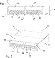
- a concrete wooden ceiling element 20 consisting of horizontally spaced support beams 22 and a bottom 24 arranged therebetween is shown.
- the bottom 24 is in the illustrated embodiment of board stacks, but it can also be formed by a solid wood panel or several adjacent wooden boards. Also conceivable is the use of plastic or wood-plastic mixed materials.
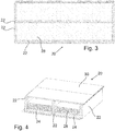
- FIG. 3 shows the concrete wooden ceiling element 20 from above. This makes it clear that 20 support bars 22 are also provided on the front sides of the elongated concrete wooden ceiling element. In the example shown, these have the same width as the longitudinal support bars 22, but they may also have a smaller diameter.
- FIGS. 1 to 4 and 9 are provided as the bottom 24 plates, which are provided on a bottom 23 of the concrete wooden ceiling element 20 between the support beam 22. They may be connected to the support bars 22 in a suitable manner, for example glued, screwed, dowelled, nailed and / or riveted.
- the support bars 22 have a vertical height H, which exceeds the height of the connecting elements 24. This results in between the support free spaces 26, which are filled as needed.
- concrete material 28, represented by hatching is located in the free spaces.
- cover elements 30 are shown, which limit and close the concrete wood ceiling element 20 or the free spaces 26 upwards or on the upper side.
- cover for example, screed can be applied, but it is also conceivable direct application of, for example, laminate or carpet.
- a further cover 34 is provided.
- This non-load-bearing cover 34 may be provided for visual reasons and / or for reasons of fire safety. It offers, for example, a cover 34 made of plasterboard, Fermacell® or equivalent material.
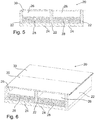
- FIGS. 5 to 8 show a second embodiment of the invention in which the bottom 24 do not extend in the sense between the support beam 22 that they have contact with each other in shock, but form a continuous layer on which the support bars 22 are arranged.
- the support bars 22 are, so to speak, on the floor 24. This may be formed as a continuous plate, as shown, or from a plurality of individual juxtaposed boards.
- a cover member 30 may also be provided.
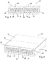
- FIGS. 7 and 8 show a variant in which additionally an insulating layer 36 is disposed within the spaces 26.
- the insulation layer 36 is located directly on the floor 24, that is to say between the floor 24 and the concrete material 28.
- the insulation layer 36 can also be arranged laterally along the support beams 22 be to also decouple the support bars 22 from the concrete material 28.
- the insulating layer 36 may be thermally and / or acoustically optimized, that is, consist of a suitably suitable material.
- FIG. 9 illustrates that the concrete wood ceiling element 20 according to the invention can have different dimensions.
- four free spaces 26 are provided, that is corresponding to five support beams 22nd
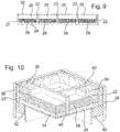
- FIG. 10 and 11 show the attachment of a concrete wooden ceiling element 20 according to the invention in the corner region of two walls 38. Visible are stitch bars 40 which extend at right angles to each other.
- the concrete wooden ceiling element 20 is mounted on each of the walls 38 fixed supports 42.
- the use of Spax screws 44 per ceiling / stitch beam 40 is indicated.
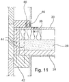
- FIG. 11 shows the use of a wall anchor 46, which is connected by means of nails 48 with the wall 38 and the concrete wooden ceiling element 20 according to the invention.
- the attachment / assembly of the concrete wooden ceiling element 20 according to the invention does not differ substantially from the installation of a conventional wooden floor tile element according to the prior art.
- the use of the concrete wood ceiling element 20 according to the invention is not a serious problem, an adaptation of the assembly steps is not or only to a small extent necessary.
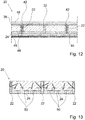
- Fig. 12 shows a particularly advantageous embodiment of the invention. It can be seen that the concrete wooden ceiling element 20 is executed in cross-section double U-shaped, consisting of three support beams 22 and interposed shelves 24.
- the respective outer support bars 22 are made a little less wide and abut the outer support beam 22 of the adjacent concrete wood ceiling element 20. Die between the support beam 22 arranged bottoms 24 are each glued to the support beam 22 and / or nailed or pegged.
- the outer support bars 22 are slightly less high than the central support bar 22 executed so that on its free top a board 42 can be arranged, which then adjusts the same height H as the central support beam 22. Between the outer support beams a joint tape 44 is still recognizable.
- an insulating layer 36 is provided, on which in turn cement screed 46 is arranged.
- a suspended ceiling 48 can be seen.
- Fig. 13 shows a particularly advantageous embodiment of the concrete wood ceiling element 20.
- the bottom 24 has a profile which counteracts lateral thrust forces and / or movements of the concrete material 28.
- the profile is formed by depressions 50 in the bottom 24, which can be performed at gradual grooves.
- the concrete material 28 is introduced into the free space sixth 20 and hardens in the recesses 50, so that it is held in a form-fitting manner, in particular in the horizontal direction.
- retaining elements 52 projecting from the base 24 and / or from the support beams 22 can also be provided, which likewise counteract pushing forces and / or movements of the concrete material 28. Even with these offers themselves that these are first introduced into the bottom 24 and / or the support beams 22, and only then the free spaces 26 are filled with concrete material. Alternatively, however, the holding elements 52 can also be subsequently introduced into the already hardened concrete material 28.
- the concrete concrete ceiling elements 20 shown are only to be seen as exemplary embodiments, in particular, for example, the bottom 24 may be designed differently, it may also be used other filling materials or it may be dispensed with the cover 30.
- the free spaces 26 shown in the embodiments may be completely filled.
- an acoustic drum effect is avoided and / or the thermal insulation is improved.
Abstract
Die Erfindung betrifft ein Betonholzdeckenelement (20), bestehend aus beabstandeten Tragebalken (22) mit dazwischen angeordneten und befestigten Verbindungselementen (24). Die Höhe der Tragebalken (22) übersteigt die Höhe (H) der Verbindungselemente (24), so dass zwischen den Tragebalken (22) Freiräume (26) ausgebildet sind, die zumindest zum Teil mit Betonmaterial (28) gefüllt sind.The invention relates to a concrete wooden ceiling element (20), consisting of spaced support beams (22) with arranged and fastened connecting elements (24). The height of the support bar (22) exceeds the height (H) of the connecting elements (24), so that between the support bar (22) free spaces (26) are formed which are at least partially filled with concrete material (28).
Description
Die Erfindung betrifft eine Holzdecke bzw. ein Betonholzdeckenelement, das insbesondere für Geschossdecken geeignet ist.The invention relates to a wooden ceiling or a concrete wooden ceiling element, which is particularly suitable for floor slabs.
Es sind Balkendecken bekannt, die im Wesentlichen aus Holz bestehen, aber akustisch sehr nachteilig sind. Auch sind Geschossdecken aus Brettstapelelementen verbreitet, die aus massiven, flächigen Bauteilen bestehen. Sie werden aus nebeneinander angeordneten Brettern mit Nägeln oder Hartholzstabdübeln zusammengefügt. Alternativ können diese auch verklebt werden. Die Nachteile der Brettstapelbauweise sind außerdem in eine schlechte Schallschutzdämmung im Rohzustand sowie eine problematische Auflagerausbildung bei Decken. Insbesondere weisen derartige Geschossdecken auch ein ungünstiges Schwingverhalten auf.There are known beam ceilings, which consist essentially of wood, but acoustically very disadvantageous. Also, floor slabs are made of board stack elements, which consist of solid, flat components. They are assembled from boards arranged side by side with nails or hardwood dowels. Alternatively, these can also be glued. The disadvantages of the Brettstapelbauweise are also in a poor sound insulation in the raw state and a problem Auflagerausbildung at ceilings. In particular, such floor slabs also have an unfavorable vibration behavior.
Die Aufgabe der Erfindung besteht darin, eine verbesserte Deckenkonstruktion, insbesondere ein verbessertes Deckenelement zu schaffen. Die Nachteile des Stands der Technik sollen hierbei vermieden werden, insbesondere soll die Deckenkonstruktion möglichst schwingungsfrei sein.The object of the invention is to provide an improved ceiling construction, in particular an improved ceiling element. The disadvantages of the prior art should be avoided, in particular the ceiling construction should be as free of vibration as possible.
Die Aufgabe wird durch ein Betonholzdeckenelement mit den Merkmalen des unabhängigen Patentanspruchs 1 gelöst.The object is achieved by a concrete wooden ceiling element with the features of independent claim 1.
Demnach besteht ein erfindungsgemäßes Betonholzdeckenelement aus voneinander beabstandeten Tragebalken und einem Boden, vorzugsweise gebildet aus Brettern. Der Boden ist vorzugsweise als Brettstapel ausgebildet, wie sie auch bei einer Brettstapeldecke verwendet werden. Die Formulierung, dass sich die Verbindungselemente zwischen den Tragebalken befinden ist dabei aber derart zu verstehen, dass die Verbindungselemente von einem Tragebalken bis zum benachbarten Tragebalken erreichen, sodass aushärtbares Betonmaterial zwischen die Tragebalken einfüllbar ist. Die Bretter des Bodens können auch derartige Dimensionen aufweisen bzw. derart lang sein, dass sie mehrere Tragebalken, wie weiter unten beschrieben, verbinden oder abdecken.Accordingly, a concrete wood ceiling element according to the invention consists of spaced support beams and a floor, preferably formed of boards. The floor is preferably formed as a stack of boards, as they are used in a board pile ceiling. However, the wording that the connecting elements are located between the support beams is understood to mean that the connecting elements reach from one support beam to the adjacent support beam, so that hardenable concrete material can be filled in between the support beams. The boards of the floor may also have such dimensions or be so long that they connect or cover a plurality of support beams, as described below.
Ein besonderer Vorteil der erfindungsgemäßen Betonholzdeckenelemente besteht darin, dass diese im Gegensatz zu herkömmlichen Betondecken eine deutlich höhere Tragfähigkeit aufweisen. Aufgrund der Tragebalkenkonstruktion ergeben sich günstigere Kraftlinien, die dazu führen, dass beim Einbau der Geschossdecken auf sonst übliche Stützen gänzlich verzichtet werden kann. Solche Stützen werden ansonsten während des Befüllens mit Beton und während der Aushärtphase des Betons gesetzt, bis dieser selbst tragen kann.A particular advantage of the concrete wood ceiling elements according to the invention is that they have a significantly higher load capacity in contrast to conventional concrete ceilings. Due to the support beam construction results in more favorable lines of force, which mean that when installing the floor slabs on otherwise common supports can be completely dispensed with. Such supports are otherwise set during filling with concrete and during the curing phase of the concrete until it can carry itself.
Die erfindungsgemäßen Betonholzdeckenelemente sind stirnseitig durch quer verlaufende Tragebalken verschlossen. Somit ergibt sich eine Art Rahmen, gebildet durch zumindest zwei längs und zwei quer verlaufende Tragebalken. Die quer verlaufenden Tragebalken können tragend oder nichttragend ausgeführt sein. Je nach späterer örtlicher Verwendung des Betonholzdeckenelements kann also auch die Nutzung eines Abschlussbretts mit geringerem Durchmesser ausreichen.The concrete wooden ceiling elements according to the invention are closed at the ends by transversely extending support beams. This results in a kind of frame formed by at least two longitudinal and two transverse support beams. The transverse support beams can be designed to be load-bearing or non-load-bearing. Depending on the later local use of the concrete wood ceiling element, therefore, the use of a cover board with a smaller diameter can be sufficient.
In den Freiräumen zwischen den Tragebalken ist Betonmaterial und/oder spezielles thermisches und/oder akustisches Isoliermaterial oder ähnliches angeordnet.In the spaces between the support beams concrete material and / or special thermal and / or acoustic insulating material or the like is arranged.
Beispielsweise kann zunächst eine Schicht aus thermisch und/oder akustisch isolierendem Material wie Glaswolle oder ähnliches in den Freiraum eingebracht werden, die dann mit dem Betonmaterial abgedeckt wird. Denkbar ist auch, dass zunächst Betonmaterial in den Freiraum eingebracht und ein verbleibender Raum anschließend mit isolierendem Material gefüllt wird.For example, first a layer of thermally and / or acoustically insulating material such as glass wool or the like can be introduced into the free space, which is then covered with the concrete material. It is also conceivable that initially introduced concrete material in the free space and a remaining space is then filled with insulating material.
Die gefüllten Freiräume sind vorzugsweise durch Abdeckelemente verschlossen. Wird aus den Betonholzdeckenelementen eine Geschossdecke gebildet, können die Abdeckelemente hochwertig ausgeführt sein, beispielsweise mit Parkett oder Laminat und somit unmittelbar als Fußboden für das obere Geschoss dienen. Die Abdeckelemente können vorzugsweise also ebenfalls aus Holz gefertigt sein, sie können aber auch als Konstruktionsfläche für den weiteren Fußbodenaufbau, beispielsweise Estrich oder Trockenestrich dienen.The filled free spaces are preferably closed by cover elements. If a floor slab is formed from the concrete wood ceiling elements, the cover elements can be made of high quality, for example with parquet or laminate and thus serve directly as a floor for the upper floor. The cover elements may therefore preferably also be made of wood, but they can also serve as a construction surface for the further floor structure, such as screed or dry screed.
Durch die Füllung der Freiräume können die Eigenschaften des Betonholzdeckenelements nahezu nach Belieben eingestellt werden. Insbesondere ist es möglich, die Masse einer Holzdecke wesentlich zu erhöhen, um auch die thermische oder akustische Isolierung zu verbessern. Die Freiräume können dabei vollständig mit Beton, beispielsweise auch in Verbindung mit einem geeigneten Schüttgut und ggfs. weiteren Materialien ausgefüllt werden, es kann aber ausreichen, diese nur zu 30 bis 90 %, vorzugsweise 50 bis 70 % zu befüllen.By filling the open spaces, the properties of the concrete wood ceiling element can be set almost as desired. In particular, it is possible to substantially increase the mass of a wooden ceiling in order to improve the thermal or acoustic insulation. The open spaces can be completely with it Concrete, for example, in conjunction with a suitable bulk material and, if necessary, other materials are filled, but it may be sufficient to fill them only to 30 to 90%, preferably 50 to 70%.
Das erfindungsgemäße Betonholzdeckenelement ist vorzugsweise ausschließlich aus Holz zuzüglich des entsprechenden Betonmaterials gefertigt. Denkbar ist aber auch, dass die Verbindungselemente oder sogar die Tragebalken aus Kunststoff oder anderen Materialen bestehen.The concrete wood ceiling element according to the invention is preferably made exclusively of wood plus the corresponding concrete material. It is also conceivable that the fasteners or even the support bars made of plastic or other materials.
Beispielsweise kann ein erfindungsgemäßes Betonholzdeckenelement doppel-U-förmig ausgeführt sein, bestehend aus drei Tragebalken und dazwischen angeordnetem. Beispielsweise hat sich eine Länge von 3 m und eine Breite von insgesamt 1,25 m als besonders vorteilhaft erwiesen. Es ist also aus drei horizontal beanstandeten Tragebalken gebildet, die eine Höhe von 0,17 m bis 0,36 m aufweisen. In Längsrichtung endseitig sind an den beiden Stirnseiten jeweils quer verlaufende Tragebalken vorgesehen, wodurch sich zwischen den Tragebalken in diesem Ausführungsbeispiel zwei Freiräume mit einem Gesamtvolumen von etwa 0,341 m3 ergeben, die mit Betonmaterial gefüllt sind. Die Breite, die Höhe und die Länge der Tragebalken und somit auch der Freiräume dazwischen sind durch die statischen Anforderungen des Baukörpers bestimmt und können an diesen angepasst werden, die oben genannten Dimensionen sind somit nur beispielhaft zu verstehen.For example, a concrete wood ceiling element according to the invention can be embodied as double-U-shaped, consisting of three supporting beams and arranged therebetween. For example, a length of 3 m and a width of 1.25 m in total has proven to be particularly advantageous. It is thus formed from three horizontally spaced support beams, which have a height of 0.17 m to 0.36 m. In the longitudinal direction end, respectively transverse support beams are provided at the two end faces, resulting in two clearances between the support beams in this embodiment with a total volume of about 0.341 m 3 , which are filled with concrete material. The width, the height and the length of the support beams and thus also of the free spaces in between are determined by the static requirements of the building and can be adapted to these, the above dimensions are thus to be understood as exemplary only.
Oberseitig kann das erfindungsgemäße Betonholzdeckenelement in dieser Variante mithilfe eines Abdeckelements, beispielsweise einer Grobspanplatte (OSB-Platte) oder andere Werkstoffe abgedeckt bzw. verschlossen. Insgesamt weist ein solches Deckenelement in Abhängigkeit der Rohdichte des Holzes und der Masse des Schüttguts etwa 200 bis 350 kg/m2, vorzugsweise 250 bis 300 kg/m2 flächenbezogene Masse auf.On the upper side, the concrete wood ceiling element according to the invention can be covered or closed in this variant by means of a cover element, for example a coarse chipboard (OSB board) or other materials. Overall, such a ceiling element depending on the density of the wood and the bulk of the bulk material about 200 to 350 kg / m 2 , preferably 250 to 300 kg / m 2 basis weight.
In einer besonders vorteilhaften Ausführungsvariante kann aber auf die Grobspanplatte (OSB-Platte) sogar vollständig verzichtet werden, das Betonholzdeckenelement ist sozusagen abdeckplattenfrei ausgeführt.In a particularly advantageous embodiment, however, the coarse chipboard (OSB board) can even be completely dispensed with, the concrete wood ceiling element being executed, so to speak, without a cover plate.
Messungen haben ergeben, dass der bewertete Norm-Trittschallpegel des erfindungsgemäßen Betonholzdeckenelements weniger als 50 dB beträgt, er lässt sich je nach Ausführungsvariante bis auf etwa 30 dB reduzieren, beispielsweise durch Nutzung eines zusätzlichen Trockenestrichs, der auf das Betonholzdeckenelement aufgetragen wird und/oder durch Verwendung einer zusätzlichen Trittschalldämmplatte. Erfindungsgemäß kann auch eine abgehängte Decke, die an das Betonholzdeckenelement anschließt, in die akustischen Überlegungen einbezogen werden. Es ist möglich, die den Trittschallpegel auch durch die abgehängte Decke weiter zu reduzieren.Measurements have shown that the evaluated standard impact sound level of the concrete wood ceiling element according to the invention is less than 50 dB, it can be depending on the variant, reduce to about 30 dB, for example by using an additional dry screed, which is applied to the concrete wood ceiling element and / or by using an additional impact sound insulation board. According to the invention, a suspended ceiling adjoining the concrete wooden ceiling element can also be included in the acoustic considerations. It is possible to further reduce the impact sound level through the suspended ceiling.
Eine Deckenkonstruktion basierend auf erfindungsgemäßen Betonholzdeckenelement hat das Potenzial, in Kombination mit schwimmenden Trockenestrichen die verschärften Anforderungen der DIN 4109 für Mehrfamilienhäuser zuverlässig einzuhalten. Es ist sogar wahrscheinlich, dass bei weiterer Optimierung der Konstruktion auch die Anforderungen an Einfamilien-, Reihen-und Doppelhäusern eingehalten werden.A ceiling construction based on concrete wood ceiling element according to the invention has the potential, in combination with floating dry screeds, to reliably comply with the stricter requirements of DIN 4109 for multi-family dwellings. It is even likely that as the design progresses, the requirements for single-family, terraced and semi-detached houses will be met.
Das Betonholzdeckenelement kann im Querschnitt L-förmig ausgeführt sein, bestehend aus einem Tragebalken und dem sich daran anschließenden Boden. Das freie Ende des Bodens wird bei Bildung einer durchgehenden Holzdecke mit Tragebalken des benachbarten L-förmigen Betonholzdeckenelements verbunden, beispielsweise verleimt, vernagelt oder verschraubt. Auch ist eine Schraub-Leim oder Nagel-Leim-Verbindung möglich. Durch die Verbindung zweier Betonholzdeckenelemente bzw. deren Tragebalken ergibt sich statisch eine Scheibenwirkung, die für die Gebäudestatik besonders vorteilhaft ist.The concrete wooden ceiling element can be designed in cross-section L-shaped, consisting of a support beam and the adjoining floor. The free end of the floor is connected with the formation of a continuous wooden ceiling with support beams of the adjacent L-shaped concrete wood ceiling element, for example, glued, nailed or screwed. Also, a screw glue or nail glue connection is possible. The combination of two concrete wood ceiling elements or their support bars results statically a disk effect, which is particularly advantageous for building statics.
Erfindungsgemäß können die Tragebalken durch den Boden bzw. die Bretter miteinander verbunden sein, die jeweils zwischen zwei Tragebalken angeordnet sind. Von unten sind dann jeweils die Tragebalken und die dazwischen angeordneten Verbindungselemente sichtbar. Alternativ kann vorgesehen sein, dass die Verbindungselemente nicht nur die Last tragen, sondern auch als eine Art Sichtblende dienen. Die Tragebalken setzen dann beispielsweise auf ein einziges flächiges Verbindungselement auf und sind mit diesem fest verbunden, beispielsweise verklebt, verschraubt, verdübelt oder vernagelt. In diesem Fall ist von unten nur das Verbindungselement, beispielsweise ausgeführt als sichtbare Trägerplatte sichtbar.According to the invention, the support beams can be connected to each other by the floor or the boards, which are each arranged between two supporting beams. From below each of the support beams and the interposed connecting elements are visible. Alternatively it can be provided that the connecting elements not only carry the load, but also serve as a kind of screen. The support beams then set, for example, on a single planar connecting element and are firmly connected to this, for example glued, screwed, dowelled or nailed. In this case, only the connecting element, for example embodied as a visible carrier plate, is visible from below.
Das erfindungsgemäße Betonholzdeckenelement kann Brandschutzvorgaben wie F30B, F60B oder F90B erfüllen. Die Feuerschutzklasse der Betonholzdeckenelemente ergibt sich dabei in erster Linie aus der Bodenhöhe des Betonholzdeckenelements. Zusätzlich kann eine nichttragende Abdeckung auf der Unterseite vorgesehen sein, beispielsweise gebildet durch eine Gipskarton- bzw. Gipsfaserplatte oder andere feuerhemmenden Bekleidungen, wodurch der Brandschutz zusätzlich erhöht werden kann. Die Unterseite kann nach dem Einbau auch verputzt werden. Um die Feuerfestigkeit weiter zu erhöhen können die Tragebalken alternativ auch aus Stahl gebildet sein, die beispielsweise mit Gipskartonplatten abgedeckt sind. Dadurch lassen sich Brandschutzvorgaben wie beispielsweise F30A, F60A oder F90A erreichen.The concrete wooden ceiling element according to the invention can fulfill fire protection requirements such as F30B, F60B or F90B. The fire protection class of the concrete wood ceiling elements results primarily from the floor height of the concrete wood ceiling element. In addition, a non-load-bearing cover may be provided on the underside, for example formed by a plasterboard or gypsum fiber board or other fire-retardant clothing, whereby the fire protection can be additionally increased. The underside can also be plastered after installation. In order to further increase the fire resistance, the support beams may alternatively also be made of steel, which are covered, for example, with plasterboard. As a result, fire protection requirements such as F30A, F60A or F90A can be achieved.
Grundsätzlich gilt für sämtliche Ausführungen des erfindungsgemäßen Betonholzdeckenelements, dass diese mit sichtbarer Unterseite (SI) oder nicht sichtbarer Unterseite (NSI) ausgeführt sein können. Die Ausführung mit sichtbarer Unterseite bedeutet, dass das Betonholzdeckenelement nach der Montage als Geschossdecke unverändert von unten sichtbar bleibt.Basically applies to all versions of the concrete wood ceiling element according to the invention that they can be designed with visible bottom (SI) or non-visible bottom (NSI). The version with visible underside means that the concrete wooden ceiling element remains visible from below as a floor slab after installation.
Grundsätzlich ist das erfindungsgemäße Betonholzdeckenelement für jede Geschossdecke geeignet, aber auch als Dachelement zur Errichtung von Dächern. Dabei kann anstelle des Schüttguts vorzugsweise ein Isolationsmaterial wie beispielsweise Glaswolle eingebracht sein. Insbesondere eignet sich das erfindungsgemäße Betonholzdeckenelement als Sparrenelement.In principle, the concrete wood ceiling element according to the invention is suitable for every floor slab, but also as a roof element for the construction of roofs. In this case, instead of the bulk material preferably an insulating material such as glass wool may be introduced. In particular, the concrete wood ceiling element according to the invention is suitable as a rafter element.
Denkbar ist auch die Verwendung als Flachdachabdeckung für Massivhäuser, auch dabei können die Vorzüge der erfindungsgemäßen Betonholzdeckenelemente genutzt werden.It is also conceivable use as a flat roof cover for solid houses, also the advantages of the concrete wood ceiling elements according to the invention can be used.
Schließlich ist auch die Verwendung als Geschossdecke in einem Massivhaus vorteilhaft, da die Fertigung und Montage schnell und einfach erfolgen kann und keine Feuchtigkeit in den Rohbau eingebracht wird. Das erfindungsgemäße Betonholzdeckenelement kann insbesondere auch als Trenndecke zwischen Wohneinheiten bei mehrgeschossiger Bauweise eingesetzt werden.Finally, the use as a floor slab in a solid house is advantageous because the production and installation can be done quickly and easily and no moisture is introduced into the shell. The concrete wood ceiling element according to the invention can be used in particular as a partition between housing units in multi-storey construction.
Ein wesentlicher Vorteil der Füllung des Betonholzdeckenelements mit Betonmaterial besteht auch in der hohen Wärmespeicherkapazität des Betons. Gerade in Heizperioden ist dies sehr vorteilhaft.A significant advantage of filling the concrete wood ceiling element with concrete material is also the high heat storage capacity of the concrete. Especially in heating periods, this is very advantageous.
In einer besonders vorteilhaften Ausführungsvariante ist zwischen dem Abdeckelement und den Tragebalken eine akustische Entkopplung vorgesehen. Beispielsweise kann eine Lage aus einem elastomeren Material auf den Tragebalken aufgebracht werden, auf das dann wiederum das Abdeckelement befestigt wird. Auch ist es möglich, dass Betonholzdeckenelement oberseitig mit einer Lattung aus beanstandeten einzelnen Brettern oder Balken vorzusehen, wobei das Abdeckelement auf diese Lattung aufgebracht wird. Auch dadurch wird die Übertragung des Körperschalls zwischen den Tragebalken und dem Abdeckelement reduziert. Auch eine Kombination einer zusätzlichen Materiallage zur akustischen Entkopplung und der Verwendung der Lattung ist denkbar, nämlich durch Anordnung einer Lattung, die unterseitig, also in Richtung der Tragebalken, eine zusätzliche Lage aus akustisch dämmendem Material, beispielsweise einem Elastomer aufweist. Ein akustischer Trommeleffekt, der sich möglicherweise durch einen Freiraum unterhalb des Abdeckelements ergibt, kann erfindungsgemäß auch durch Einbringen eines zusätzlichen akustisch dämmenden Materials aufgehoben oder zumindest reduziert werden. Erfindungsgemäß können Abdeckelemente auch unterseitig, also in Richtung des Hohlraums mit einem akustisch dämmenden, vorzugsweise elastomeren oder weichen Material beschichtet sein.In a particularly advantageous embodiment, an acoustic decoupling is provided between the cover member and the support beam. For example, a layer of an elastomeric material can be applied to the support beam, on which in turn the cover is attached. It is also possible that concrete wooden ceiling element provided on the top side with a battens of offending individual boards or beams, wherein the cover is applied to this battens. This also reduces the transmission of structure-borne noise between the support beam and the cover. A combination of an additional material layer for acoustic decoupling and the use of the battens is also conceivable, namely by arranging a battens which has an additional layer of acoustically insulating material, for example an elastomer, on the underside, ie in the direction of the support beams. An acoustic drum effect, which possibly results from a free space below the cover element, can also be canceled or at least reduced according to the invention by introducing an additional acoustically insulating material. According to the invention, cover elements can also be coated on the underside, that is to say in the direction of the cavity, with an acoustically insulating, preferably elastomeric or soft material.
Erfindungsgemäß können über das Füllmaterial die Eigenschaften des Betonholzdeckenelements beeinflusst werden. Neben Betonmaterial mit hoher Masse ist erfindungsgemäß auch die Verwendung beispielsweise Leichtbeton möglich. Auch kann aufgemahlener Recyclingbeton als Füllmaterial für den Freiraum verwendet werden. Es ist sogar möglich, bereits ausgehärtetes Betonmaterial, beispielsweise in Form von Betonplatten in den Freiraum einzubringen.According to the invention, the properties of the concrete wood ceiling element can be influenced via the filling material. In addition to concrete material with high mass according to the invention, the use of lightweight concrete, for example, is possible. Also, ground recycled concrete can be used as filler for the clearance. It is even possible to introduce already hardened concrete material, for example in the form of concrete slabs in the free space.
Das erfindungsgemäße Betonholzdeckenelement hat weiterhin den Vorteil, dass Installationen, wie beispielsweise elektrische Leitungen, Gas-, Wasser- oder Abwasserleitungen problemlos vor Einbringen des Betons innenliegend angeordnet werden können. Insbesondere können sie nach Art eines Baukastenprinzips ab Werk vormontiert sein, sodass die einzelnen Betonholzdeckenelement bzw. die integrierten Installationen vor Ort lediglich miteinander verbunden werden müssen. Betonmaterial kann sowohl ab Werk als auch vor Ort eingebracht werden, was ebenfalls vorteilhaft ist. Wird das Betonmaterial ab Werk eingefüllt, kann das Betonholzdeckenelement mit ausgehärtetem Betonmaterial vor Ort eingebaut werden. Alternativ ist es möglich, zunächst lediglich die Holzkonstruktion einzubauen, ggfs. Installationen zu verlegen, um dann das Betonmaterial oder anderes Füllmaterial vor Ort einzufüllen.The concrete wood ceiling element according to the invention has the further advantage that installations such as electrical lines, gas, water or sewage pipes can be easily placed inside before introducing the concrete. In particular, they can be pre-assembled in the manner of a modular principle from the factory, so that the individual concrete wood ceiling element or the integrated installations on site only need to be connected to each other. Concrete material can be introduced both ex works and on site, which is also advantageous. If the concrete material is filled at the factory, the concrete wood ceiling element with hardened concrete material can be installed on site. Alternatively, it is possible to initially install only the wooden structure, if necessary. To lay installations, then to fill the concrete or other filling material on site.
In einer besonders fordert Ausführungsvariante ist der Boden des Betonholzdeckenelements profiliert ausgeführt, sodass Schubkräfte in horizontaler Richtung aufgenommen werden können. Hierfür kann der Boden beispielsweise Vertiefungen in Form von Nuten aufweisen, in die das flüssige Betonmaterial vor dem Aushärten eingefüllt wird. Nach dem Aushärten ergibt sich so eine Fixierung des Betonmaterials durch Formschluss in horizontaler Richtung. Alternativ oder zusätzlich ist es auch möglich, dass vom Boden und/oder von den Tragebalken Elemente, wie beispielsweise Nägel oder Schrauben in die Freiräume hineinragen. Auch in diesem Fall umschließt das ausgehärtete Betonmaterial diese Halteelemente und ist im ausgehärteten Zustand durch diese gehalten.In a particularly demanding embodiment, the bottom of the concrete wood ceiling element is profiled, so that thrust forces can be absorbed in the horizontal direction. For this purpose, the soil may, for example, have recesses in the form of grooves, into which the liquid concrete material is filled before hardening. After curing, this results in a fixation of the concrete material by positive locking in the horizontal direction. Alternatively or additionally, it is also possible for elements such as nails or screws to protrude into the free spaces from the floor and / or from the support beams. Also in this case encloses the cured concrete material, these holding elements and is held in the cured state by this.
Die Erfindung wird anhand der nachfolgenden Figuren näher erläutert diese sind nur beispielhaft zu verstehen und sollen die Erfindung nicht auf die gezeigten Ausführungsbeispiele beschränken. Es zeigen:
- Fig. 1:
- eine erste Ausführungsvariante eines erfindungsgemäßen Betonholzdeckenelements im Querschnitt,
- Fig. 2:
- das Betonholzdeckenelement aus
Fig. 1 in perspektivischer Darstellung, im Querschnitt, - Fig. 3:
- das Betonholzdeckenelement aus
Fig. 1 von oben, - Fig. 4:
- das Betonholzdeckenelement aus
Fig. 1 mit zusätzlicher nicht-tragender Abdeckschicht auf der Unterseite, - Fig. 5:
- eine zweite Ausführungsvariante eines erfindungsgemäßen Betonholzdeckenelements im Querschnitt,
- Fig. 6:
- das Betonholzdeckenelement aus
Fig. 5 in perspektivischer Darstellung, im Querschnitt, - Fig. 7:
- eine dritte Ausführungsvariante eines erfindungsgemäßen Betonholzdeckenelements im Querschnitt,
- Fig. 8:
- das Betonholzdeckenelement aus
Fig. 7 in perspektivischer Darstellung, im Querschnitt, - Fig. 9:
- eine weitere Ausführungsvariante eines erfindungsgemäßen Betonholzdeckenelements im Querschnitt,
- Fig. 10:
- perspektivische Darstellung eines Bereichs eines Betonholzdeckenelements auf einem Auflager, teilweise geschnitten,
- Fig. 11:
- Schnittdarstelllung eines Bereichs eines Betonholzdeckenelements auf einem Auflager.
- Fig. 12:
- Schnittdarstelllung eines Bereichs eines Betonholzdeckenelements gemäß einer weiteren Ausführungsvariante der Erfindung,
- Fig. 13:
- Schnittdarstellung einer weiteren vorteilhaften Ausführungsvariante der Erfindung.
- Fig. 1:
- a first embodiment of a concrete wood ceiling element according to the invention in cross-section,
- Fig. 2:
- the concrete wooden ceiling element
Fig. 1 in perspective, in cross section, - 3:
- the concrete wooden ceiling element
Fig. 1 from above, - 4:
- the concrete wooden ceiling element
Fig. 1 with additional non-wearing cover layer on the underside, - Fig. 5:
- A second embodiment of a concrete wood ceiling element according to the invention in cross section,
- Fig. 6:
- the concrete wooden ceiling element
Fig. 5 in perspective, in cross section, - Fig. 7:
- a third embodiment of a concrete wood ceiling element according to the invention in cross-section,
- Fig. 8:
- the concrete wooden ceiling element
Fig. 7 in perspective, in cross section, - Fig. 9:
- a further embodiment of a concrete wood ceiling element according to the invention in cross section,
- Fig. 10:
- perspective view of a section of a concrete wooden ceiling element on a support, partially cut,
- Fig. 11:
- Sectional view of a section of a concrete wooden ceiling element on a support.
- Fig. 12:
- Sectional view of a portion of a concrete wood ceiling element according to another embodiment of the invention,
- Fig. 13:
- Sectional view of a further advantageous embodiment of the invention.
In allen Figuren ist ein Betonholzdeckenelement 20, bestehend aus horizontal beabstandeten Tragebalken 22 und einem dazwischen angeordneten Boden 24, gezeigt. Der Boden 24 besteht in dem gezeigten Ausführungsbeispiel aus Brettstapeln, er kann aber auch durch eine massive Holzplatte bzw. mehrere benachbarte Holzbretter gebildet sein. Denkbar ist auch die Verwendung von Kunststoff- oder Holz-Kunststoff-Mischmaterialien.In all figures, a concrete
In den
Weiterhin ist sind Abdeckelemente 30 gezeigt, welches das Betonholzdeckenelement 20 bzw. die Freiräume 26 nach oben bzw. oberseitig begrenzen und abschließen. Auf das Abdeckelement kann beispielsweise Estrich aufgebracht werden, denkbar ist aber auch das unmittelbare Aufbringen von beispielsweise Laminat oder Teppich.Furthermore, cover
Bei der Ausführungsvariante gemäß
Die
Die
Die Ausführungsvariante gemäß
Die
Auf den Tragebalken 22 ist eine Isolationsschicht 36 vorgesehen, auf der wiederum Zementestrich 46 angeordnet ist. Unterhalb des Bodens 24 ist eine abgehängte Unterdecke 48 erkennbar.On the
Zusätzlich oder alternativ können auch vom Boden 24 und/der von den Tragebalken 22 abstehende Halteelemente 52 vorgesehen sein, die ebenfalls Schubkräften und/oder -bewegungen des Betonmaterials 28 entgegenwirken. Auch bei diesen bietet sich an, dass diese zunächst in den Boden 24 und/oder die Tragebalken 22 eingebracht werden, und erst danach die Freiräume 26 mit Betonmaterial gefüllt werden. Alternativ können die Halteelemente 52 aber auch nachträglich in das bereits ausgehärtete Betonmaterial 28 eingebracht werden.In addition or as an alternative, retaining elements 52 projecting from the
Die gezeigten Betonholzdeckenelemente 20 sind nur als beispielhafte Ausführungsvarianten zu sehen, insbesondere kann beispielsweise der Boden 24 andersartig ausgeführt sein, es können auch andere Füllmaterialien verwendet oder es kann auf das Abdeckelement 30 verzichtet werden.The concrete
Für alle Ausführungsbeispiele gilt, dass insbesondere die in den Ausführungsbeispielen gezeigten Freiräume 26 vollständig befüllt sein können. Dadurch wird insbesondere ein akustischer Trommeleffekt vermieden und/oder die thermische Isolation verbessert.For all embodiments, in particular, the
Claims (15)
Applications Claiming Priority (1)
| Application Number | Priority Date | Filing Date | Title |
|---|---|---|---|
| DE102018106890.5A DE102018106890A1 (en) | 2018-03-22 | 2018-03-22 | Concrete wood ceiling element |
Publications (3)
| Publication Number | Publication Date |
|---|---|
| EP3543416A1 true EP3543416A1 (en) | 2019-09-25 |
| EP3543416C0 EP3543416C0 (en) | 2023-06-07 |
| EP3543416B1 EP3543416B1 (en) | 2023-06-07 |
Family
ID=65598435
Family Applications (1)
| Application Number | Title | Priority Date | Filing Date |
|---|---|---|---|
| EP19158855.7A Active EP3543416B1 (en) | 2018-03-22 | 2019-02-22 | Reinforced wooden covering element |
Country Status (2)
| Country | Link |
|---|---|
| EP (1) | EP3543416B1 (en) |
| DE (1) | DE102018106890A1 (en) |
Cited By (2)
| Publication number | Priority date | Publication date | Assignee | Title |
|---|---|---|---|---|
| EP4043659A1 (en) * | 2021-02-12 | 2022-08-17 | MMK Holz-Beton-Fertigteile GmbH | Composite panel |
| WO2023111558A1 (en) | 2021-12-17 | 2023-06-22 | Thornton Tomasetti Limited | Floor structure |
Citations (5)
| Publication number | Priority date | Publication date | Assignee | Title |
|---|---|---|---|---|
| DE29603415U1 (en) * | 1996-01-24 | 1996-07-11 | Meyer Georg Dipl Ing Fh | Panel element |
| DE19801370A1 (en) * | 1997-02-27 | 1998-10-29 | Georg Meyer | Wall, ceiling, roof or other supporting component for building |
| DE29824534U1 (en) * | 1998-04-24 | 2001-08-02 | Bauer Werner | Wood-concrete composite element |
| DE10227099A1 (en) * | 2002-06-18 | 2004-01-15 | Weinmann Holzbausystemtechnik Gmbh | Construction element e.g. ceiling board comprises concrete layer on wooden board which comprises planks of different width in alternation with interposed cavities bridged by nails which connect wooden and concrete layers |
| DE202017104297U1 (en) * | 2016-07-19 | 2017-09-29 | Martin Opitz | Wooden ceiling element |
-
2018
- 2018-03-22 DE DE102018106890.5A patent/DE102018106890A1/en not_active Withdrawn
-
2019
- 2019-02-22 EP EP19158855.7A patent/EP3543416B1/en active Active
Patent Citations (5)
| Publication number | Priority date | Publication date | Assignee | Title |
|---|---|---|---|---|
| DE29603415U1 (en) * | 1996-01-24 | 1996-07-11 | Meyer Georg Dipl Ing Fh | Panel element |
| DE19801370A1 (en) * | 1997-02-27 | 1998-10-29 | Georg Meyer | Wall, ceiling, roof or other supporting component for building |
| DE29824534U1 (en) * | 1998-04-24 | 2001-08-02 | Bauer Werner | Wood-concrete composite element |
| DE10227099A1 (en) * | 2002-06-18 | 2004-01-15 | Weinmann Holzbausystemtechnik Gmbh | Construction element e.g. ceiling board comprises concrete layer on wooden board which comprises planks of different width in alternation with interposed cavities bridged by nails which connect wooden and concrete layers |
| DE202017104297U1 (en) * | 2016-07-19 | 2017-09-29 | Martin Opitz | Wooden ceiling element |
Cited By (2)
| Publication number | Priority date | Publication date | Assignee | Title |
|---|---|---|---|---|
| EP4043659A1 (en) * | 2021-02-12 | 2022-08-17 | MMK Holz-Beton-Fertigteile GmbH | Composite panel |
| WO2023111558A1 (en) | 2021-12-17 | 2023-06-22 | Thornton Tomasetti Limited | Floor structure |
Also Published As
| Publication number | Publication date |
|---|---|
| EP3543416C0 (en) | 2023-06-07 |
| EP3543416B1 (en) | 2023-06-07 |
| DE102018106890A1 (en) | 2019-09-26 |
Similar Documents
| Publication | Publication Date | Title |
|---|---|---|
| EP1861553B1 (en) | Self-supporting module comprising non-load bearing external walls that are pre-mounted on said module | |
| DE202017104297U1 (en) | Wooden ceiling element | |
| EP1808538A2 (en) | Construction made with individual parts | |
| EP2181227B1 (en) | Prefabricated transportable composite wall element composed of shuttering blocks | |
| EP3543416B1 (en) | Reinforced wooden covering element | |
| EP3287570A1 (en) | Wood-concrete composite element for use as ceiling, floor or wall in a building | |
| AT522516B1 (en) | Room module, building made from room modules, as well as a manufacturing process for this in each case | |
| DE102020120983B4 (en) | Room part module, in particular commercial module building made therefrom, and a manufacturing method for each | |
| EP3971361A1 (en) | Loam panel | |
| DE202007001983U1 (en) | Building wall has wood fiber insulating layer which has at least one groove or channel in which at least one installation element is located, wherein a continuous layer is located in front of slot or channel | |
| EP3015614B1 (en) | Wall panel for dry construction consisting of a wooden material and wall structure and method of manufacturing the wall structure with the wall panel | |
| EP1596017B1 (en) | Method for increasing the load capacity, the stiffness and the damping of vibrations of a wooden joist ceiling arrangement and wooden joist ceiling arrangement with increased load capacity, stiffness and damping of vibrations. | |
| DE102017118004A1 (en) | Drywall partitioning system and method of assembling such a drywall partitioning system | |
| DE19950356C2 (en) | Multi-layer building board, as well as processes for their production | |
| EP2080845A1 (en) | Prefabricated wood element | |
| EP1422356B1 (en) | Prefabricated insulated panel with heating pipes embedded in concrete and method of manufacturing | |
| DE102005040388A1 (en) | Wood and/or concrete carrying parts connection for e.g. timber panel construction, has dimensionally stable connection base inserted into sealing compound e.g. concrete, where base is made from wood, plastic and/or metal | |
| WO1997013043A1 (en) | Prefabricated solid-construction modular house | |
| DE10030729A1 (en) | Plate element for construction of walls, ceilings or roofs of buildings comprises a concrete and wooden structure provided with an inner layer which consists of a mechanically stable, self-supporting material | |
| DE102015220431A1 (en) | Concrete precast ceiling slab for use in wooden structures | |
| DE10006492A1 (en) | Prefabricated house walls has a wall section with grooved edges to fit at vertical and spaced pillars to be coupled to them in position for rapid and easy erection | |
| DE102004003366B4 (en) | Method for producing a single-family or multi-family house, precast concrete trough plate for a building ceiling and prefabricated house | |
| AT15320U1 (en) | Composite precast | |
| EP2479358B1 (en) | Method for producing a pre-fabricated floor | |
| DE202019103003U1 (en) | Room module and a building made of room modules |
Legal Events
| Date | Code | Title | Description |
|---|---|---|---|
| PUAI | Public reference made under article 153(3) epc to a published international application that has entered the european phase |
Free format text: ORIGINAL CODE: 0009012 |
|
| STAA | Information on the status of an ep patent application or granted ep patent |
Free format text: STATUS: THE APPLICATION HAS BEEN PUBLISHED |
|
| AK | Designated contracting states |
Kind code of ref document: A1 Designated state(s): AL AT BE BG CH CY CZ DE DK EE ES FI FR GB GR HR HU IE IS IT LI LT LU LV MC MK MT NL NO PL PT RO RS SE SI SK SM TR |
|
| AX | Request for extension of the european patent |
Extension state: BA ME |
|
| STAA | Information on the status of an ep patent application or granted ep patent |
Free format text: STATUS: REQUEST FOR EXAMINATION WAS MADE |
|
| 17P | Request for examination filed |
Effective date: 20200320 |
|
| RBV | Designated contracting states (corrected) |
Designated state(s): AL AT BE BG CH CY CZ DE DK EE ES FI FR GB GR HR HU IE IS IT LI LT LU LV MC MK MT NL NO PL PT RO RS SE SI SK SM TR |
|
| STAA | Information on the status of an ep patent application or granted ep patent |
Free format text: STATUS: EXAMINATION IS IN PROGRESS |
|
| 17Q | First examination report despatched |
Effective date: 20200602 |
|
| STAA | Information on the status of an ep patent application or granted ep patent |
Free format text: STATUS: EXAMINATION IS IN PROGRESS |
|
| GRAP | Despatch of communication of intention to grant a patent |
Free format text: ORIGINAL CODE: EPIDOSNIGR1 |
|
| STAA | Information on the status of an ep patent application or granted ep patent |
Free format text: STATUS: GRANT OF PATENT IS INTENDED |
|
| INTG | Intention to grant announced |
Effective date: 20220708 |
|
| GRAJ | Information related to disapproval of communication of intention to grant by the applicant or resumption of examination proceedings by the epo deleted |
Free format text: ORIGINAL CODE: EPIDOSDIGR1 |
|
| STAA | Information on the status of an ep patent application or granted ep patent |
Free format text: STATUS: EXAMINATION IS IN PROGRESS |
|
| GRAP | Despatch of communication of intention to grant a patent |
Free format text: ORIGINAL CODE: EPIDOSNIGR1 |
|
| STAA | Information on the status of an ep patent application or granted ep patent |
Free format text: STATUS: GRANT OF PATENT IS INTENDED |
|
| INTC | Intention to grant announced (deleted) | ||
| INTG | Intention to grant announced |
Effective date: 20221206 |
|
| GRAS | Grant fee paid |
Free format text: ORIGINAL CODE: EPIDOSNIGR3 |
|
| GRAA | (expected) grant |
Free format text: ORIGINAL CODE: 0009210 |
|
| STAA | Information on the status of an ep patent application or granted ep patent |
Free format text: STATUS: THE PATENT HAS BEEN GRANTED |
|
| AK | Designated contracting states |
Kind code of ref document: B1 Designated state(s): AL AT BE BG CH CY CZ DE DK EE ES FI FR GB GR HR HU IE IS IT LI LT LU LV MC MK MT NL NO PL PT RO RS SE SI SK SM TR |
|
| REG | Reference to a national code |
Ref country code: GB Ref legal event code: FG4D Free format text: NOT ENGLISH |
|
| REG | Reference to a national code |
Ref country code: CH Ref legal event code: EP Ref country code: AT Ref legal event code: REF Ref document number: 1575458 Country of ref document: AT Kind code of ref document: T Effective date: 20230615 |
|
| REG | Reference to a national code |
Ref country code: DE Ref legal event code: R096 Ref document number: 502019007848 Country of ref document: DE |
|
| U01 | Request for unitary effect filed |
Effective date: 20230707 |
|
| RAP4 | Party data changed (patent owner data changed or rights of a patent transferred) |
Owner name: MARTIN OPITZ WOHNUNGSBAU UND VERWALTUNGS GMBH UND CO. KG |
|
| U07 | Unitary effect registered |
Designated state(s): AT BE BG DE DK EE FI FR IT LT LU LV MT NL PT SE SI Effective date: 20230807 |
|
| REG | Reference to a national code |
Ref country code: LT Ref legal event code: MG9D |
|
| PG25 | Lapsed in a contracting state [announced via postgrant information from national office to epo] |
Ref country code: NO Free format text: LAPSE BECAUSE OF FAILURE TO SUBMIT A TRANSLATION OF THE DESCRIPTION OR TO PAY THE FEE WITHIN THE PRESCRIBED TIME-LIMIT Effective date: 20230907 Ref country code: ES Free format text: LAPSE BECAUSE OF FAILURE TO SUBMIT A TRANSLATION OF THE DESCRIPTION OR TO PAY THE FEE WITHIN THE PRESCRIBED TIME-LIMIT Effective date: 20230607 |
|
| PG25 | Lapsed in a contracting state [announced via postgrant information from national office to epo] |
Ref country code: RS Free format text: LAPSE BECAUSE OF FAILURE TO SUBMIT A TRANSLATION OF THE DESCRIPTION OR TO PAY THE FEE WITHIN THE PRESCRIBED TIME-LIMIT Effective date: 20230607 Ref country code: HR Free format text: LAPSE BECAUSE OF FAILURE TO SUBMIT A TRANSLATION OF THE DESCRIPTION OR TO PAY THE FEE WITHIN THE PRESCRIBED TIME-LIMIT Effective date: 20230607 Ref country code: GR Free format text: LAPSE BECAUSE OF FAILURE TO SUBMIT A TRANSLATION OF THE DESCRIPTION OR TO PAY THE FEE WITHIN THE PRESCRIBED TIME-LIMIT Effective date: 20230908 |
|
| PG25 | Lapsed in a contracting state [announced via postgrant information from national office to epo] |
Ref country code: SK Free format text: LAPSE BECAUSE OF FAILURE TO SUBMIT A TRANSLATION OF THE DESCRIPTION OR TO PAY THE FEE WITHIN THE PRESCRIBED TIME-LIMIT Effective date: 20230607 |
|
| PG25 | Lapsed in a contracting state [announced via postgrant information from national office to epo] |
Ref country code: IS Free format text: LAPSE BECAUSE OF FAILURE TO SUBMIT A TRANSLATION OF THE DESCRIPTION OR TO PAY THE FEE WITHIN THE PRESCRIBED TIME-LIMIT Effective date: 20231007 |
|
| PG25 | Lapsed in a contracting state [announced via postgrant information from national office to epo] |
Ref country code: SM Free format text: LAPSE BECAUSE OF FAILURE TO SUBMIT A TRANSLATION OF THE DESCRIPTION OR TO PAY THE FEE WITHIN THE PRESCRIBED TIME-LIMIT Effective date: 20230607 Ref country code: SK Free format text: LAPSE BECAUSE OF FAILURE TO SUBMIT A TRANSLATION OF THE DESCRIPTION OR TO PAY THE FEE WITHIN THE PRESCRIBED TIME-LIMIT Effective date: 20230607 Ref country code: RO Free format text: LAPSE BECAUSE OF FAILURE TO SUBMIT A TRANSLATION OF THE DESCRIPTION OR TO PAY THE FEE WITHIN THE PRESCRIBED TIME-LIMIT Effective date: 20230607 Ref country code: IS Free format text: LAPSE BECAUSE OF FAILURE TO SUBMIT A TRANSLATION OF THE DESCRIPTION OR TO PAY THE FEE WITHIN THE PRESCRIBED TIME-LIMIT Effective date: 20231007 Ref country code: CZ Free format text: LAPSE BECAUSE OF FAILURE TO SUBMIT A TRANSLATION OF THE DESCRIPTION OR TO PAY THE FEE WITHIN THE PRESCRIBED TIME-LIMIT Effective date: 20230607 |
|
| PG25 | Lapsed in a contracting state [announced via postgrant information from national office to epo] |
Ref country code: PL Free format text: LAPSE BECAUSE OF FAILURE TO SUBMIT A TRANSLATION OF THE DESCRIPTION OR TO PAY THE FEE WITHIN THE PRESCRIBED TIME-LIMIT Effective date: 20230607 |
|
| U20 | Renewal fee paid [unitary effect] |
Year of fee payment: 6 Effective date: 20240215 |