EP3543067A1 - Structure porteuse pour un dossier, siège et procédé de fabrication d'un siège - Google Patents
Structure porteuse pour un dossier, siège et procédé de fabrication d'un siège Download PDFInfo
- Publication number
- EP3543067A1 EP3543067A1 EP19163990.5A EP19163990A EP3543067A1 EP 3543067 A1 EP3543067 A1 EP 3543067A1 EP 19163990 A EP19163990 A EP 19163990A EP 3543067 A1 EP3543067 A1 EP 3543067A1
- Authority
- EP
- European Patent Office
- Prior art keywords
- mounting plate
- seat
- embossing
- frame
- abheftungsprägung
- Prior art date
- Legal status (The legal status is an assumption and is not a legal conclusion. Google has not performed a legal analysis and makes no representation as to the accuracy of the status listed.)
- Withdrawn
Links
Images


Classifications
-
- B—PERFORMING OPERATIONS; TRANSPORTING
- B60—VEHICLES IN GENERAL
- B60N—SEATS SPECIALLY ADAPTED FOR VEHICLES; VEHICLE PASSENGER ACCOMMODATION NOT OTHERWISE PROVIDED FOR
- B60N2/00—Seats specially adapted for vehicles; Arrangement or mounting of seats in vehicles
- B60N2/68—Seat frames
- B60N2/686—Panel like structures
-
- B—PERFORMING OPERATIONS; TRANSPORTING
- B60—VEHICLES IN GENERAL
- B60N—SEATS SPECIALLY ADAPTED FOR VEHICLES; VEHICLE PASSENGER ACCOMMODATION NOT OTHERWISE PROVIDED FOR
- B60N2/00—Seats specially adapted for vehicles; Arrangement or mounting of seats in vehicles
- B60N2/58—Seat coverings
- B60N2/5816—Seat coverings attachments thereof
- B60N2/5825—Seat coverings attachments thereof by hooks, staples, clips, snap fasteners or the like
Definitions
- the invention relates to a support structure for a seat back of a vehicle seat.
- the invention further relates to a seat with such a support structure and a method for manufacturing the seat.
- the invention is based on the object to provide an improved support structure with an improved reference holder.
- the invention is further based on the object to provide an improved seat and a suitable method for producing such a seat.
- the object is achieved according to the invention with the features specified in claim 1.
- the object is achieved according to the invention with the features specified in claim 13.
- the object is achieved according to the invention with the features specified in claim 15.
- a support structure according to the invention for a seat or backrest of a seat comprises a frame, for. B. a back frame, with at least two vertical frame elements and at least one Crossmember.
- the support structure further comprises a mounting plate, z. B. a back plate, which has at least one connection embossing for fixed connection of the frame to the mounting plate and at least one Abheftungsyogown for attaching a reference element on the mounting plate, the at least one connecting embossing and the at least one Abheftungs ceremonies overlap partially.
- planar surface Due to the region-wise overlap of Abheftungs tenugung and connecting embossing a planar surface of the mounting plate is increased.
- the planar surface is intended in particular for the arrangement of a reference element, such as a carpet, a fabric or a natural material, such as leather.
- the at least one Abheftungsconcegung is introduced as a longitudinal recess in the mounting plate.
- the Abheftungsconcegung is introduced in the form of an elongated bead or groove in the mounting plate, in particular molded, as pressed.
- a reference element can be arranged and fixed.
- the at least one connecting embossing can be introduced as a punctiform or stepped depression in the mounting plate and is located to increase the planar surface of the mounting plate partially in the Abheftungsconcegung.
- the connection embossing can also be introduced as a bead or groove in the mounting plate, in particular molded, as pressed.
- the fastening plate has a plurality of connection embossings, wherein the at least one embossing embossing overlaps in some areas with one of the connection embossings.
- a stamping area of the supporting structure is significantly reduced.
- the frame may comprise at least two substantially vertical frame members and at least one associated cross member.
- the frame elements and / or the cross member each have, for example, a hollow profile, in particular a round profile element and / or a square profile.
- the vertical frame members from round profile elements, in particular tubes are formed.
- the cross member may be formed of a square profile.
- the frame members and cross members can also be made of similar profile elements, for. B. square profiles may be formed.
- the frame elements are each connected to the cross member by means of a plug connection in a form-fitting or positive and non-positive manner at the end.
- the frame members and the cross member are inserted into each other in corner areas.
- additional fastening means for. As screws, be provided for a frictional connection of the frame members with the cross member.
- an overlapping region of the at least one embossing embossing and the at least one connecting embossing is arranged in the region of the crossmember.
- At least one component for receiving a headrest of the seat can be arranged on the cross member.
- the component has a hollow profile for receiving headrest mounts. This allows the adjustment of an optimal headrest position.
- the support structure comprises a ver Weggungsshake support surface on which the reference element is arranged or can be arranged.
- the support surface is increased compared to the prior art due to the partially overlapping arranged connection embossing and Abheftungsconce.
- an improved arrangement of the reference element, in particular a seat cover is possible.
- the reference element is for example a carpet, a fabric and / or a natural material, such. B. leather.
- the reference element comprises two reference parts, which are sewn together.
- the reference element is sewn in the region of the Abheftungsyogettigung with the mounting plate.
- reference marginal edges are arranged in the Abprftungsgargung and sewn there with the mounting plate. This allows a visually appealing stitching of the reference element.
- the binding of the reference element with such a stitching is overall stable and resistant.
- a seat which comprises the support structure according to the invention.
- the support structure may be part of a seat part, a seat or backrest adjustable relative to the seat part, and / or a headrest.
- the seat has by means of the support structure on a comparison with the prior art improved reference bracket.
- a method for producing a seat in which - the at least one connection embossing and the at least one Abheftungsyogown are partially overlapping introduced into the mounting plate, wherein the mounting plate is attached to the frame, wherein for fastening the mounting plate on the frame at least a clamping element is positioned on the mounting plate, by means of which the frame and the mounting plate are clamped at least in sections, wherein at least in an overlap region of connection embossing and Abheftungsconce a welding tool is arranged engaging, by means of which the at least partially tensioned mounting plate is welded to the frame and wherein the reference element arranged on a ver rempligungsELI support surface of the mounting plate and is secured in the at least one Abheftungsconce.
- connection embossing and embossing embossing can be made stiff enough to arrange the at least one clamping element there and thus to significantly reduce the embossing area of the supporting structure.
- connection embossing can for example be formed so large in the mounting or backing plate that above and below the welding tool in each case a clamping element can be arranged.
- Figures 9A and 9B schematic sectional views of a hooking profile.
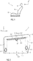
- FIG. 1 schematically shows a side view of a seat S, which is described below in a Cartesian coordinate system with three mutually perpendicular spatial directions X, Y, Z.
- the seat S is for example a vehicle seat, in particular a rear seat of a second row of seats, and comprises a seat part ST, a relative to Seat part ST in its inclination adjustable seat or backrest RL and a headrest K.
- FIG. 2 schematically shows a perspective view of a front view of a support structure 1 for in FIG. 1 shown seat or backrest RL of the seat S.
- the support structure 1 has as large a surface as possible planar or even, especially non-embossing support surface 1.1 for a reference to be arranged on this element BZ (see FIG. 9 ), such as a carpet, a woven fabric or a natural material such as leather.
- the support structure 1 further comprises a frame 2 and a mounting plate 3, which are fixedly connected to each other, in particular welded together.
- the frame 2 is in particular a back frame and the mounting plate 3 is a back plate.
- the frame 2 comprises at least two substantially vertical frame elements 2.1 and at least one cross member 2.2 connected thereto on the upper side.
- the frame 2 is essentially formed from hollow profiles, in particular round profile elements and / or square profile elements.
- the vertical frame elements 2.1 are formed from round profile elements, in particular tubes.
- the cross member 2.2 is formed in particular of a square profile.
- frame members 2.1 and cross member 2.2 may be formed of similar profile elements, in particular square profiles.
- connection embossing 3.1 which are designed in particular as punctiform depressions or step-shaped recesses.
- connection embossings 3.1 can also be introduced as a bead and / or groove in the mounting plate 3.
- the introduction of the connection embossings 3.1 can in particular by molding, such. B. impressions done.
- three connection embossings 3.1 are shown.
- the mounting plate 3 for fastening, in particular for stapling a reference element BZ (shown in the FIGS. 7 . 8th ) on the mounting plate 3 at least one Abheftungsconcegung 3.2.
- the Abheftungsgargung 3.2 is introduced, for example in the form of an elongated bead or groove in the mounting plate 3, in particular molded, such as. B. pressed. In the exemplary embodiment shown, a back of the Abheftungsconcegung 3.2 is shown so that it protrudes from the image plane.
- the reference element BZ for example, a seat cover of two reference parts, which are sewn together to form a seam tab.
- the reference element BZ further has reference marginal edges, which are lined, for example, and with which the reference element BZ is introduced in the Abheftungsyoggung 3.2.
- An attachment of the reference element BZ in the Abheftungsyoggung 3.2, for example, by the reference edge edges are sewn in the Abheftungsyoggung 3.2 with the mounting plate 3.
- the mounting plate 3 to this in Abfeftungsgargung 3.2 suitable for sewing profile, z. B. a profile strip have.
- the Abheftungsconcegung 3.2 in the FIGS. 7 to 9B have shown as an example Einitatiprofil P to which the reference element BZ form, force and / or cohesively fastened.
- the at least one Abheftungsconcegung 3.2 partially overlaps with at least one of the connection embossings 3.1.
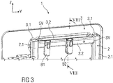
- FIG. 3 schematically shows a perspective view of the support structure 1 in plan view of the frame 2.
- the overlap region B of Abfeftungsgargung 3.2 and 3.1 connecting embossment is provided in the region of the cross member 2.2 and is covered.
- the frame 2 is formed of square profiles, which are inserted into each other in corner areas and thus at least positively connected to each other by means of a connector SV.
- components B1, B2 are further arranged, which form receptacles for headrest mounts, not shown.
- the components B1, B2 have in particular hollow profiles.
- the component B2 is exemplified in FIG. 8 shown.
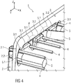
- FIG. 4 schematically shows a perspective view of the support structure 1 during a connection process with arranged in this clamping elements 4 and in the region of some connecting embossments 3.1 engaging welding tool 5 with welding pins 5.1 for spacing.
- the mounting plate 3 to the frame 2 When connecting, in particular welding, the mounting plate 3 to the frame 2 usually clamping elements 4, such as pins or pins, used for compressing mounting plate 3 and frame 2. As a result, a distance between to be welded surfaces of Fastening plate 3 and frame 2 set and maintained in the region of the connection embossings 3.1, so that they can be welded together by means of the welding tool 5.
- clamping elements 4 such as pins or pins
- connection embossing 3.1 Due to the overlapping regions of connection embossing 3.1 and Abheftungsggigung 3.2, the local area in addition to the actual attachment, in particular weld stiff enough to arrange the one or more clamping elements 4 there and thus significantly reduce a required for mounting embossing area.
- the connection embossing 3.1 is formed so large in the mounting plate 3 that above and below the welding pin 5.1 each one clamping element 4 can be arranged.
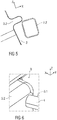
- FIG. 5 schematically shows an enlarged sectional view in the field of Abheftungsggigung 3.2 and with the arranged below this cross member 2.2.
- FIG. 6 schematically shows a perspective view of an enlarged detail in an overlap region B of a connection embossing 3.1 and a Abheftungsggigung 3.2 and with a arranged in this overlap region B clamping element 4 as a spacer.
- FIG. 7 schematically shows an enlarged sectional view in the region of a connection stamping 3.1 for attachment of the frame 2, in particular of the cross member 2.2, to the mounting plate.
- FIG. 8 schematically shows an enlarged sectional view in the region of a Abheftungsgargung 3.2 for fastening the reference element BZ to the mounting plate 3 partially in its Abheftungsconcegung 3.2.
- the frame 2 below the Abheftungsggigung 3.2 extends the frame 2, in particular the cross member 2.2.
- the mounting plate 3 has a region circumferential and slightly curved or angled sheet edge 3.3, followed by a substantially flat surface adjoins, which forms the support surface 1.1.
- the mounting plate 3 and the frame 2 are arranged on or in a pad 6, as in both FIGS. 7 and 8th is shown.
- the Abheftungsconcegung 3.2 projects into a recess of the pad 6 inside.
- the frame 2, in particular the cross member 2.2 can, as in FIG. 8 shown, partially completely surrounded by the pad 6.
- FIG. 7 a portion of the cross member 2.2 is arranged in one of the vertical frame members 2.1.
- the pad 6 is at least partially covered with the reference element BZ, which in turn is attached and held by means of the hooking profile P in the Abheftungsconcegung 3.2.
- the reference element BZ in the region of a substantially flat support surface 1.1 of the support structure 1, in particular a flat region of the mounting plate 3 can be arranged flat on this and rest.
- the suspension profile P is attached to a free end of the reference element BZ and designed such that it positively or non-positively on the mounting plate 3, in particular in its Abheftungsoniagung 3.2, engages and is fixed there, for example, clipped, plugged or latched is held.
- the mounting plate 3 can also be provided in regions with a lining 7, for example, a panel or a carpet.
- FIGS. 9A and 9B show schematically sectional views, in particular cross sections, two different embodiments of a Hooking profile P for fastening the reference element BZ in the stitching embossing 3.2.
- suspension profile P has a J-shaped cross-section.
- FIG. 9B shown suspension profile P has a cross section with a hook-shaped end, wherein the opposite end has an upside-down T-shape.
- Conceivable are other cross sections that allow attachment of the reference element BZ.
- the angled end of the J-shaped cross section or the protruding hooks of the hook-shaped end of the respective hooking profile P are used for fastening the hooking profile P in the stitching embossing 3.2, in particular by hooking, by snapping or by plugging.
Landscapes
- Engineering & Computer Science (AREA)
- Aviation & Aerospace Engineering (AREA)
- Transportation (AREA)
- Mechanical Engineering (AREA)
- Seats For Vehicles (AREA)
Applications Claiming Priority (1)
| Application Number | Priority Date | Filing Date | Title |
|---|---|---|---|
| DE102018204276 | 2018-03-20 |
Publications (1)
| Publication Number | Publication Date |
|---|---|
| EP3543067A1 true EP3543067A1 (fr) | 2019-09-25 |
Family
ID=65904070
Family Applications (1)
| Application Number | Title | Priority Date | Filing Date |
|---|---|---|---|
| EP19163990.5A Withdrawn EP3543067A1 (fr) | 2018-03-20 | 2019-03-20 | Structure porteuse pour un dossier, siège et procédé de fabrication d'un siège |
Country Status (1)
| Country | Link |
|---|---|
| EP (1) | EP3543067A1 (fr) |
Citations (7)
| Publication number | Priority date | Publication date | Assignee | Title |
|---|---|---|---|---|
| EP0606179A1 (fr) * | 1993-01-07 | 1994-07-13 | Bertrand Faure Automobile "B.F.A." | Dispositif d'accrochage des bords des coiffes de coussins de sièges |
| DE102006004531B3 (de) * | 2005-03-22 | 2007-08-16 | Faurecia Autositze Gmbh | Rückenlehne für einen Fahrzeugsitz |
| WO2008061233A2 (fr) * | 2006-11-16 | 2008-05-22 | Johnson Controls Technology Company | Châssis de dossier de siège de véhicule et procédé |
| FR2911096A1 (fr) * | 2007-01-09 | 2008-07-11 | Faurecia Sieges Automobile | Structure de siege de vehicule et siege comportant une telle structure |
| DE202013100620U1 (de) * | 2012-11-16 | 2013-04-08 | Prevent Twb Gmbh & Co. Kg | Rückenlehne für einen Fahrzeugsitz |
| DE102013218096B4 (de) | 2013-02-27 | 2014-12-24 | Johnson Controls Components Gmbh & Co. Kg | Rückenlehne für einen Sitz, insbesondere einen Fahrzeugsitz |
| EP2867062A1 (fr) | 2012-06-29 | 2015-05-06 | Peugeot Citroën Automobiles SA | Elément de siège pour véhicule automobile |
-
2019
- 2019-03-20 EP EP19163990.5A patent/EP3543067A1/fr not_active Withdrawn
Patent Citations (7)
| Publication number | Priority date | Publication date | Assignee | Title |
|---|---|---|---|---|
| EP0606179A1 (fr) * | 1993-01-07 | 1994-07-13 | Bertrand Faure Automobile "B.F.A." | Dispositif d'accrochage des bords des coiffes de coussins de sièges |
| DE102006004531B3 (de) * | 2005-03-22 | 2007-08-16 | Faurecia Autositze Gmbh | Rückenlehne für einen Fahrzeugsitz |
| WO2008061233A2 (fr) * | 2006-11-16 | 2008-05-22 | Johnson Controls Technology Company | Châssis de dossier de siège de véhicule et procédé |
| FR2911096A1 (fr) * | 2007-01-09 | 2008-07-11 | Faurecia Sieges Automobile | Structure de siege de vehicule et siege comportant une telle structure |
| EP2867062A1 (fr) | 2012-06-29 | 2015-05-06 | Peugeot Citroën Automobiles SA | Elément de siège pour véhicule automobile |
| DE202013100620U1 (de) * | 2012-11-16 | 2013-04-08 | Prevent Twb Gmbh & Co. Kg | Rückenlehne für einen Fahrzeugsitz |
| DE102013218096B4 (de) | 2013-02-27 | 2014-12-24 | Johnson Controls Components Gmbh & Co. Kg | Rückenlehne für einen Sitz, insbesondere einen Fahrzeugsitz |
Similar Documents
| Publication | Publication Date | Title |
|---|---|---|
| DE102008053138B4 (de) | Hakenelement und Haltestruktur für Bezugsmaterial | |
| DE102011053354B4 (de) | Kombinierte Struktur einer äußeren oberen Mittelsäulenverstärkung und eines Sicherheitsgurthalters und Schweißverfahren unter Verwendung dieser Struktur | |
| DE10158401B4 (de) | Moduldach für ein Kraftfahrzeug und Verfahren zu seiner Montage | |
| DE102015207480B4 (de) | Clipanbringaufbau für einen fahrzeugsitz | |
| DE102010062445A1 (de) | Sitzverkleidungsanordnung | |
| DE102005013613A1 (de) | Kraftfahrzeugsitz | |
| DE19825225A1 (de) | Wölbungsverstellbare Stütze, insbesondere Lordosenstütze, für Sitze und Liegen aller Art | |
| DE102013213995B4 (de) | Rückenlehne für einen Fahrzeugsitz und Fahrzeugsitz | |
| DE102005060446A1 (de) | Fahrzeugsitz, insbesondere Kraftfahrzeugsitz | |
| DE102019200576A1 (de) | Fahrzeugsitz | |
| DE102018117118A1 (de) | Schiene für Fahrzeugsitz und Fahrzeugsitz umfassend eine solche Schiene | |
| DE3013568A1 (de) | Fahrzeugsitz | |
| DE102019114909A1 (de) | Abdeckung zur Auskleidung einer Durchgangsöffnung in einem Polsterteil eines Fahrzeugsitzes, Verfahren zur Montage einer Abdeckung an ein Sitzteil eines Fahrzeugsitzes, sowie Fahrzeugsitz | |
| DE102014219173B4 (de) | Verkehrsmittelsitz | |
| DE102008061738A1 (de) | Kopfstütze, insbesondere für Fahrzeugsitz | |
| DE102013218096A1 (de) | Lehnensitzrahmen für einen Sitz, insbesondere einen Fahrzeugsitz und Fahrzeugsitz | |
| WO2020173884A1 (fr) | Revêtement pour une pièce de rembourrage d'un siège de véhicule, pièce de rembourrage pour un siège de véhicule et siège de véhicule | |
| EP3931042A1 (fr) | Revêtement pour une pièce de rembourrage d'un siège de véhicule, pièce de rembourrage pour un siège de véhicule et siège de véhicule | |
| DE10104007C2 (de) | Fahrzeugsitz, insbesondere Sportwagensitz | |
| DE102017200946A1 (de) | Befestigungsvorrichtung zur Befestigung eines Sitzbezugs | |
| DE102017209583B4 (de) | Kopfstützenanordnung für ein Fahrzeug | |
| EP3543067A1 (fr) | Structure porteuse pour un dossier, siège et procédé de fabrication d'un siège | |
| DE8120010U1 (de) | Vorrichtung zum steppen von polsterungen, insbesondere fuer sitze u.dgl. | |
| DE102017222015A1 (de) | Verkleidungselement zur Verkleidung einer Seitenfläche eines Fahrzeuginnenraums | |
| DE102022103219A1 (de) | Fahrzeugsitz |
Legal Events
| Date | Code | Title | Description |
|---|---|---|---|
| PUAI | Public reference made under article 153(3) epc to a published international application that has entered the european phase |
Free format text: ORIGINAL CODE: 0009012 |
|
| STAA | Information on the status of an ep patent application or granted ep patent |
Free format text: STATUS: THE APPLICATION HAS BEEN PUBLISHED |
|
| AK | Designated contracting states |
Kind code of ref document: A1 Designated state(s): AL AT BE BG CH CY CZ DE DK EE ES FI FR GB GR HR HU IE IS IT LI LT LU LV MC MK MT NL NO PL PT RO RS SE SI SK SM TR |
|
| AX | Request for extension of the european patent |
Extension state: BA ME |
|
| STAA | Information on the status of an ep patent application or granted ep patent |
Free format text: STATUS: REQUEST FOR EXAMINATION WAS MADE |
|
| 17P | Request for examination filed |
Effective date: 20200325 |
|
| RBV | Designated contracting states (corrected) |
Designated state(s): AL AT BE BG CH CY CZ DE DK EE ES FI FR GB GR HR HU IE IS IT LI LT LU LV MC MK MT NL NO PL PT RO RS SE SI SK SM TR |
|
| GRAP | Despatch of communication of intention to grant a patent |
Free format text: ORIGINAL CODE: EPIDOSNIGR1 |
|
| STAA | Information on the status of an ep patent application or granted ep patent |
Free format text: STATUS: GRANT OF PATENT IS INTENDED |
|
| INTG | Intention to grant announced |
Effective date: 20210118 |
|
| STAA | Information on the status of an ep patent application or granted ep patent |
Free format text: STATUS: THE APPLICATION IS DEEMED TO BE WITHDRAWN |
|
| 18D | Application deemed to be withdrawn |
Effective date: 20210529 |