EP3543067A1 - Supporting structure for a seat back, seat and method for producing a seat - Google Patents
Supporting structure for a seat back, seat and method for producing a seat Download PDFInfo
- Publication number
- EP3543067A1 EP3543067A1 EP19163990.5A EP19163990A EP3543067A1 EP 3543067 A1 EP3543067 A1 EP 3543067A1 EP 19163990 A EP19163990 A EP 19163990A EP 3543067 A1 EP3543067 A1 EP 3543067A1
- Authority
- EP
- European Patent Office
- Prior art keywords
- mounting plate
- seat
- embossing
- frame
- abheftungsprägung
- Prior art date
- Legal status (The legal status is an assumption and is not a legal conclusion. Google has not performed a legal analysis and makes no representation as to the accuracy of the status listed.)
- Withdrawn
Links
Images


Classifications
-
- B—PERFORMING OPERATIONS; TRANSPORTING
- B60—VEHICLES IN GENERAL
- B60N—SEATS SPECIALLY ADAPTED FOR VEHICLES; VEHICLE PASSENGER ACCOMMODATION NOT OTHERWISE PROVIDED FOR
- B60N2/00—Seats specially adapted for vehicles; Arrangement or mounting of seats in vehicles
- B60N2/68—Seat frames
- B60N2/686—Panel like structures
-
- B—PERFORMING OPERATIONS; TRANSPORTING
- B60—VEHICLES IN GENERAL
- B60N—SEATS SPECIALLY ADAPTED FOR VEHICLES; VEHICLE PASSENGER ACCOMMODATION NOT OTHERWISE PROVIDED FOR
- B60N2/00—Seats specially adapted for vehicles; Arrangement or mounting of seats in vehicles
- B60N2/58—Seat coverings
- B60N2/5816—Seat coverings attachments thereof
- B60N2/5825—Seat coverings attachments thereof by hooks, staples, clips, snap fasteners or the like
Definitions
- the invention relates to a support structure for a seat back of a vehicle seat.
- the invention further relates to a seat with such a support structure and a method for manufacturing the seat.
- the invention is based on the object to provide an improved support structure with an improved reference holder.
- the invention is further based on the object to provide an improved seat and a suitable method for producing such a seat.
- the object is achieved according to the invention with the features specified in claim 1.
- the object is achieved according to the invention with the features specified in claim 13.
- the object is achieved according to the invention with the features specified in claim 15.
- a support structure according to the invention for a seat or backrest of a seat comprises a frame, for. B. a back frame, with at least two vertical frame elements and at least one Crossmember.
- the support structure further comprises a mounting plate, z. B. a back plate, which has at least one connection embossing for fixed connection of the frame to the mounting plate and at least one Abheftungsyogown for attaching a reference element on the mounting plate, the at least one connecting embossing and the at least one Abheftungs ceremonies overlap partially.
- planar surface Due to the region-wise overlap of Abheftungs tenugung and connecting embossing a planar surface of the mounting plate is increased.
- the planar surface is intended in particular for the arrangement of a reference element, such as a carpet, a fabric or a natural material, such as leather.
- the at least one Abheftungsconcegung is introduced as a longitudinal recess in the mounting plate.
- the Abheftungsconcegung is introduced in the form of an elongated bead or groove in the mounting plate, in particular molded, as pressed.
- a reference element can be arranged and fixed.
- the at least one connecting embossing can be introduced as a punctiform or stepped depression in the mounting plate and is located to increase the planar surface of the mounting plate partially in the Abheftungsconcegung.
- the connection embossing can also be introduced as a bead or groove in the mounting plate, in particular molded, as pressed.
- the fastening plate has a plurality of connection embossings, wherein the at least one embossing embossing overlaps in some areas with one of the connection embossings.
- a stamping area of the supporting structure is significantly reduced.
- the frame may comprise at least two substantially vertical frame members and at least one associated cross member.
- the frame elements and / or the cross member each have, for example, a hollow profile, in particular a round profile element and / or a square profile.
- the vertical frame members from round profile elements, in particular tubes are formed.
- the cross member may be formed of a square profile.
- the frame members and cross members can also be made of similar profile elements, for. B. square profiles may be formed.
- the frame elements are each connected to the cross member by means of a plug connection in a form-fitting or positive and non-positive manner at the end.
- the frame members and the cross member are inserted into each other in corner areas.
- additional fastening means for. As screws, be provided for a frictional connection of the frame members with the cross member.
- an overlapping region of the at least one embossing embossing and the at least one connecting embossing is arranged in the region of the crossmember.
- At least one component for receiving a headrest of the seat can be arranged on the cross member.
- the component has a hollow profile for receiving headrest mounts. This allows the adjustment of an optimal headrest position.
- the support structure comprises a ver Weggungsshake support surface on which the reference element is arranged or can be arranged.
- the support surface is increased compared to the prior art due to the partially overlapping arranged connection embossing and Abheftungsconce.
- an improved arrangement of the reference element, in particular a seat cover is possible.
- the reference element is for example a carpet, a fabric and / or a natural material, such. B. leather.
- the reference element comprises two reference parts, which are sewn together.
- the reference element is sewn in the region of the Abheftungsyogettigung with the mounting plate.
- reference marginal edges are arranged in the Abprftungsgargung and sewn there with the mounting plate. This allows a visually appealing stitching of the reference element.
- the binding of the reference element with such a stitching is overall stable and resistant.
- a seat which comprises the support structure according to the invention.
- the support structure may be part of a seat part, a seat or backrest adjustable relative to the seat part, and / or a headrest.
- the seat has by means of the support structure on a comparison with the prior art improved reference bracket.
- a method for producing a seat in which - the at least one connection embossing and the at least one Abheftungsyogown are partially overlapping introduced into the mounting plate, wherein the mounting plate is attached to the frame, wherein for fastening the mounting plate on the frame at least a clamping element is positioned on the mounting plate, by means of which the frame and the mounting plate are clamped at least in sections, wherein at least in an overlap region of connection embossing and Abheftungsconce a welding tool is arranged engaging, by means of which the at least partially tensioned mounting plate is welded to the frame and wherein the reference element arranged on a ver rempligungsELI support surface of the mounting plate and is secured in the at least one Abheftungsconce.
- connection embossing and embossing embossing can be made stiff enough to arrange the at least one clamping element there and thus to significantly reduce the embossing area of the supporting structure.
- connection embossing can for example be formed so large in the mounting or backing plate that above and below the welding tool in each case a clamping element can be arranged.
- Figures 9A and 9B schematic sectional views of a hooking profile.
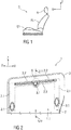
- FIG. 1 schematically shows a side view of a seat S, which is described below in a Cartesian coordinate system with three mutually perpendicular spatial directions X, Y, Z.
- the seat S is for example a vehicle seat, in particular a rear seat of a second row of seats, and comprises a seat part ST, a relative to Seat part ST in its inclination adjustable seat or backrest RL and a headrest K.
- FIG. 2 schematically shows a perspective view of a front view of a support structure 1 for in FIG. 1 shown seat or backrest RL of the seat S.
- the support structure 1 has as large a surface as possible planar or even, especially non-embossing support surface 1.1 for a reference to be arranged on this element BZ (see FIG. 9 ), such as a carpet, a woven fabric or a natural material such as leather.
- the support structure 1 further comprises a frame 2 and a mounting plate 3, which are fixedly connected to each other, in particular welded together.
- the frame 2 is in particular a back frame and the mounting plate 3 is a back plate.
- the frame 2 comprises at least two substantially vertical frame elements 2.1 and at least one cross member 2.2 connected thereto on the upper side.
- the frame 2 is essentially formed from hollow profiles, in particular round profile elements and / or square profile elements.
- the vertical frame elements 2.1 are formed from round profile elements, in particular tubes.
- the cross member 2.2 is formed in particular of a square profile.
- frame members 2.1 and cross member 2.2 may be formed of similar profile elements, in particular square profiles.
- connection embossing 3.1 which are designed in particular as punctiform depressions or step-shaped recesses.
- connection embossings 3.1 can also be introduced as a bead and / or groove in the mounting plate 3.
- the introduction of the connection embossings 3.1 can in particular by molding, such. B. impressions done.
- three connection embossings 3.1 are shown.
- the mounting plate 3 for fastening, in particular for stapling a reference element BZ (shown in the FIGS. 7 . 8th ) on the mounting plate 3 at least one Abheftungsconcegung 3.2.
- the Abheftungsgargung 3.2 is introduced, for example in the form of an elongated bead or groove in the mounting plate 3, in particular molded, such as. B. pressed. In the exemplary embodiment shown, a back of the Abheftungsconcegung 3.2 is shown so that it protrudes from the image plane.
- the reference element BZ for example, a seat cover of two reference parts, which are sewn together to form a seam tab.
- the reference element BZ further has reference marginal edges, which are lined, for example, and with which the reference element BZ is introduced in the Abheftungsyoggung 3.2.
- An attachment of the reference element BZ in the Abheftungsyoggung 3.2, for example, by the reference edge edges are sewn in the Abheftungsyoggung 3.2 with the mounting plate 3.
- the mounting plate 3 to this in Abfeftungsgargung 3.2 suitable for sewing profile, z. B. a profile strip have.
- the Abheftungsconcegung 3.2 in the FIGS. 7 to 9B have shown as an example Einitatiprofil P to which the reference element BZ form, force and / or cohesively fastened.
- the at least one Abheftungsconcegung 3.2 partially overlaps with at least one of the connection embossings 3.1.
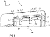
- FIG. 3 schematically shows a perspective view of the support structure 1 in plan view of the frame 2.
- the overlap region B of Abfeftungsgargung 3.2 and 3.1 connecting embossment is provided in the region of the cross member 2.2 and is covered.
- the frame 2 is formed of square profiles, which are inserted into each other in corner areas and thus at least positively connected to each other by means of a connector SV.
- components B1, B2 are further arranged, which form receptacles for headrest mounts, not shown.
- the components B1, B2 have in particular hollow profiles.
- the component B2 is exemplified in FIG. 8 shown.
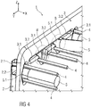
- FIG. 4 schematically shows a perspective view of the support structure 1 during a connection process with arranged in this clamping elements 4 and in the region of some connecting embossments 3.1 engaging welding tool 5 with welding pins 5.1 for spacing.
- the mounting plate 3 to the frame 2 When connecting, in particular welding, the mounting plate 3 to the frame 2 usually clamping elements 4, such as pins or pins, used for compressing mounting plate 3 and frame 2. As a result, a distance between to be welded surfaces of Fastening plate 3 and frame 2 set and maintained in the region of the connection embossings 3.1, so that they can be welded together by means of the welding tool 5.
- clamping elements 4 such as pins or pins
- connection embossing 3.1 Due to the overlapping regions of connection embossing 3.1 and Abheftungsggigung 3.2, the local area in addition to the actual attachment, in particular weld stiff enough to arrange the one or more clamping elements 4 there and thus significantly reduce a required for mounting embossing area.
- the connection embossing 3.1 is formed so large in the mounting plate 3 that above and below the welding pin 5.1 each one clamping element 4 can be arranged.
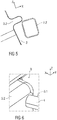
- FIG. 5 schematically shows an enlarged sectional view in the field of Abheftungsggigung 3.2 and with the arranged below this cross member 2.2.
- FIG. 6 schematically shows a perspective view of an enlarged detail in an overlap region B of a connection embossing 3.1 and a Abheftungsggigung 3.2 and with a arranged in this overlap region B clamping element 4 as a spacer.
- FIG. 7 schematically shows an enlarged sectional view in the region of a connection stamping 3.1 for attachment of the frame 2, in particular of the cross member 2.2, to the mounting plate.
- FIG. 8 schematically shows an enlarged sectional view in the region of a Abheftungsgargung 3.2 for fastening the reference element BZ to the mounting plate 3 partially in its Abheftungsconcegung 3.2.
- the frame 2 below the Abheftungsggigung 3.2 extends the frame 2, in particular the cross member 2.2.
- the mounting plate 3 has a region circumferential and slightly curved or angled sheet edge 3.3, followed by a substantially flat surface adjoins, which forms the support surface 1.1.
- the mounting plate 3 and the frame 2 are arranged on or in a pad 6, as in both FIGS. 7 and 8th is shown.
- the Abheftungsconcegung 3.2 projects into a recess of the pad 6 inside.
- the frame 2, in particular the cross member 2.2 can, as in FIG. 8 shown, partially completely surrounded by the pad 6.
- FIG. 7 a portion of the cross member 2.2 is arranged in one of the vertical frame members 2.1.
- the pad 6 is at least partially covered with the reference element BZ, which in turn is attached and held by means of the hooking profile P in the Abheftungsconcegung 3.2.
- the reference element BZ in the region of a substantially flat support surface 1.1 of the support structure 1, in particular a flat region of the mounting plate 3 can be arranged flat on this and rest.
- the suspension profile P is attached to a free end of the reference element BZ and designed such that it positively or non-positively on the mounting plate 3, in particular in its Abheftungsoniagung 3.2, engages and is fixed there, for example, clipped, plugged or latched is held.
- the mounting plate 3 can also be provided in regions with a lining 7, for example, a panel or a carpet.
- FIGS. 9A and 9B show schematically sectional views, in particular cross sections, two different embodiments of a Hooking profile P for fastening the reference element BZ in the stitching embossing 3.2.
- suspension profile P has a J-shaped cross-section.
- FIG. 9B shown suspension profile P has a cross section with a hook-shaped end, wherein the opposite end has an upside-down T-shape.
- Conceivable are other cross sections that allow attachment of the reference element BZ.
- the angled end of the J-shaped cross section or the protruding hooks of the hook-shaped end of the respective hooking profile P are used for fastening the hooking profile P in the stitching embossing 3.2, in particular by hooking, by snapping or by plugging.
Abstract
Die Erfindung betrifft eine Tragkonstruktion (1) für eine Sitz- oder Rückenlehne (RL) eines Sitzes (S), umfassend- einen Rahmen (2) mit zumindest zwei vertikalen Rahmenelementen (2.1) und mindestens einem Querträger (2.2) und- ein Befestigungsblech (3), welchesmindestens eine Verbindungsprägung (3.1) zur festen Verbindung des Rahmens (2) mit dem Befestigungsblech (3) und zumindest eine Abheftungsprägung (3.2) zur Befestigung eines Bezugselements (BZ) am Befestigungsblech (3) aufweist,- wobei die mindestens eine Verbindungsprägung (3.1) und die zumindest eine Abheftungsprägung (3.2) bereichsweise überlappen.Die Erfindung betrifft weiterhin einen Sitz (S) mit einer solchen Tragkonstruktion (1) sowie ein Verfahren zur Herstellung eines solchen Sitzes (S).The invention relates to a supporting structure (1) for a seat or backrest (RL) of a seat (S) comprising a frame (2) with at least two vertical frame elements (2.1) and at least one cross member (2.2) and a mounting plate (2). 3), which has at least one connecting embossing (3.1) for the fixed connection of the frame (2) to the fastening plate (3) and at least one embossing embossing (3.2) for fastening a reference element (BZ) to the fastening plate (3), wherein the at least one connecting embossing The invention further relates to a seat (S) with such a support structure (1) and to a method for producing such a seat (S).
Description
Die Erfindung betrifft eine Tragkonstruktion für eine Sitzlehne eines Fahrzeugsitzes. Die Erfindung betrifft weiterhin einen Sitz mit einer solchen Tragkonstruktion sowie ein Verfahren zur Herstellung des Sitzes.The invention relates to a support structure for a seat back of a vehicle seat. The invention further relates to a seat with such a support structure and a method for manufacturing the seat.
Aus dem Stand der Technik ist aus
Der Erfindung liegt die Aufgabe zu Grunde, eine verbesserte Tragkonstruktion mit einer verbesserten Bezugshalterung anzugeben. Der Erfindung liegt weiterhin die Aufgabe zu Grunde, einen verbesserten Sitz sowie ein geeignetes Verfahren zur Herstellung eines solchen Sitzes anzugeben.The invention is based on the object to provide an improved support structure with an improved reference holder. The invention is further based on the object to provide an improved seat and a suitable method for producing such a seat.
Hinsichtlich der Tragkonstruktion wird die Aufgabe erfindungsgemäß mit den in Anspruch 1 angegebenen Merkmalen gelöst. Hinsichtlich des Sitzes wird die Aufgabe erfindungsgemäß mit den in Anspruch 13 angegebenen Merkmalen gelöst. Hinsichtlich des Verfahrens wird die Aufgabe erfindungsgemäß mit den in Anspruch 15 angegebenen Merkmalen gelöst.With regard to the support structure, the object is achieved according to the invention with the features specified in
Eine erfindungsgemäße Tragkonstruktion für eine Sitz- oder Rückenlehne eines Sitzes umfasst einen Rahmen, z. B. einen Lehnenrahmen, mit zumindest zwei vertikalen Rahmenelementen und mindestens einem Querträger. Die Tragkonstruktion umfasst weiterhin ein Befestigungsblech, z. B. ein Rückenblech, welches mindestens eine Verbindungsprägung zur festen Verbindung des Rahmens mit dem Befestigungsblech und zumindest eine Abheftungsprägung zur Befestigung eines Bezugselements am Befestigungsblech aufweist, wobei die mindestens eine Verbindungsprägung und die zumindest eine Abheftungsprägung bereichsweise überlappen.A support structure according to the invention for a seat or backrest of a seat comprises a frame, for. B. a back frame, with at least two vertical frame elements and at least one Crossmember. The support structure further comprises a mounting plate, z. B. a back plate, which has at least one connection embossing for fixed connection of the frame to the mounting plate and at least one Abheftungsprägung for attaching a reference element on the mounting plate, the at least one connecting embossing and the at least one Abheftungsprägung overlap partially.
Aufgrund der bereichsweisen Überlappung von Abheftungsprägung und Verbindungsprägung ist eine planare Fläche des Befestigungsbleches vergrößert. Die planare Fläche ist insbesondere zur Anordnung eines Bezugselements, wie zum Beispiel eines Teppichs, eines Gewebes oder eines Naturmaterials, wie Leder, vorgesehen.Due to the region-wise overlap of Abheftungsprägung and connecting embossing a planar surface of the mounting plate is increased. The planar surface is intended in particular for the arrangement of a reference element, such as a carpet, a fabric or a natural material, such as leather.
Gemäß einem Ausführungsbeispiel ist die zumindest eine Abheftungsprägung als eine längs verlaufende Vertiefung in das Befestigungsblech eingebracht. Insbesondere ist die Abheftungsprägung in Form einer länglichen Sicke oder Nut in das Befestigungsblech eingebracht, insbesondere eingeformt, wie eingedrückt. In der Abheftungsprägung kann ein Bezugselement angeordnet und befestigt werden.According to one embodiment, the at least one Abheftungsprägung is introduced as a longitudinal recess in the mounting plate. In particular, the Abheftungsprägung is introduced in the form of an elongated bead or groove in the mounting plate, in particular molded, as pressed. In Abfeftungsprägung a reference element can be arranged and fixed.
Die mindestens eine Verbindungsprägung kann als eine punktuelle oder stufenförmige Vertiefung in das Befestigungsblech eingebracht sein und befindet sich zur Vergrößerung der planaren Fläche des Befestigungsblechs bereichsweise in der Abheftungsprägung. Die Verbindungsprägung kann weiterhin auch als Sicke oder Nut in das Befestigungsblech eingebracht, insbesondere eingeformt, wie eingedrückt sein.The at least one connecting embossing can be introduced as a punctiform or stepped depression in the mounting plate and is located to increase the planar surface of the mounting plate partially in the Abheftungsprägung. The connection embossing can also be introduced as a bead or groove in the mounting plate, in particular molded, as pressed.
Gemäß einem weiteren Ausführungsbeispiel weist das Befestigungsblech mehrere Verbindungsprägungen auf, wobei die zumindest eine Abheftungsprägung mit einer der Verbindungsprägungen bereichsweise überlappt. Dadurch, dass eine der Verbindungsprägungen und die Abheftungsprägung bereichsweise überlappen, ist ein Prägungsbereich der Tragkonstruktion signifikant verkleinert.According to a further exemplary embodiment, the fastening plate has a plurality of connection embossings, wherein the at least one embossing embossing overlaps in some areas with one of the connection embossings. In that one of the connection impressions and the Overlapping embossing stamping area by area, a stamping area of the supporting structure is significantly reduced.
Des Weiteren kann der Rahmen zumindest zwei im Wesentlichen vertikale Rahmenelemente und mindestens einen damit verbundenen Querträger umfassen. Die Rahmenelemente und/oder der Querträger weisen beispielsweise jeweils ein Hohlprofil, insbesondere ein Rundprofilelement und/oder ein Vierkantprofil auf. Beispielsweise sind die vertikalen Rahmenelemente aus Rundprofilelementen, insbesondere Rohren gebildet. Der Querträger kann aus einem Vierkantprofil gebildet sein. Des Weiteren können die Rahmenelemente und Querträger auch aus gleichartigen Profilelementen, z. B. Vierkantprofilen gebildet sein.Furthermore, the frame may comprise at least two substantially vertical frame members and at least one associated cross member. The frame elements and / or the cross member each have, for example, a hollow profile, in particular a round profile element and / or a square profile. For example, the vertical frame members from round profile elements, in particular tubes are formed. The cross member may be formed of a square profile. Furthermore, the frame members and cross members can also be made of similar profile elements, for. B. square profiles may be formed.
Gemäß einem weiteren Ausführungsbeispiel sind die Rahmenelemente jeweils endseitig mit dem Querträger mittels einer Steckverbindung formschlüssig oder form- und kraftschlüssig miteinander verbunden. Insbesondere sind die Rahmenelemente und der Querträger in Eckbereichen ineinander gesteckt. Dabei können zusätzliche Befestigungsmittel, z. B. Schrauben, für eine kraftschlüssige Verbindung der Rahmenelemente mit dem Querträger vorgesehen sein.According to a further exemplary embodiment, the frame elements are each connected to the cross member by means of a plug connection in a form-fitting or positive and non-positive manner at the end. In particular, the frame members and the cross member are inserted into each other in corner areas. In this case, additional fastening means, for. As screws, be provided for a frictional connection of the frame members with the cross member.
Gemäß einem Ausführungsbeispiel ist ein Überlappungsbereich der zumindest einen Abheftungsprägung und der mindestens einen Verbindungsprägung im Bereich des Querträgers angeordnet. Dadurch kann die Tragkonstruktion besonders stabil ausgeführt werden.According to one exemplary embodiment, an overlapping region of the at least one embossing embossing and the at least one connecting embossing is arranged in the region of the crossmember. As a result, the support structure can be made particularly stable.
Ferner kann am Querträger mindestens ein Bauteil zur Aufnahme einer Kopfstütze des Sitzes angeordnet sein. Insbesondere weist das Bauteil ein Hohlprofil zur Aufnahme von Kopfstützenhalterungen auf. Dies ermöglicht die Einstellung einer optimalen Kopfstützenposition.Further, at least one component for receiving a headrest of the seat can be arranged on the cross member. In particular, the component has a hollow profile for receiving headrest mounts. This allows the adjustment of an optimal headrest position.
Gemäß einem weiteren Ausführungsbeispiel umfasst die Tragkonstruktion eine verprägungsfreie Stützfläche, auf welcher das Bezugselement angeordnet oder anordenbar ist. Die Stützfläche ist aufgrund der bereichsweise überlappend angeordneten Verbindungsprägung und Abheftungsprägung gegenüber dem Stand der Technik vergrößert. Dadurch ist eine verbesserte Anordnung des Bezugselements, insbesondere eines Sitzbezuges, möglich.According to a further embodiment, the support structure comprises a verprägungsfreie support surface on which the reference element is arranged or can be arranged. The support surface is increased compared to the prior art due to the partially overlapping arranged connection embossing and Abheftungsprägung. As a result, an improved arrangement of the reference element, in particular a seat cover, is possible.
Das Bezugselement ist beispielsweise ein Teppich, ein Gewebe und/oder ein Naturmaterial, wie z. B. Leder. Insbesondere umfasst das Bezugselement zwei Bezugsteile, die miteinander vernäht sind.The reference element is for example a carpet, a fabric and / or a natural material, such. B. leather. In particular, the reference element comprises two reference parts, which are sewn together.
Gemäß einem weiteren Ausführungsbeispiel ist das Bezugselement im Bereich der Abheftungsprägung mit dem Befestigungsblech vernäht. Dazu werden beispielsweise Bezugs-Randkanten in der Abheftungsprägung angeordnet und dort mit dem Befestigungsblech vernäht. Dies ermöglicht eine optisch ansprechende Abheftung des Bezugselements. Zudem ist die Abheftung des Bezugselements mit einer derartigen Vernähung insgesamt stabil und beständig ausgebildet.According to a further embodiment, the reference element is sewn in the region of the Abheftungsprägung with the mounting plate. For this purpose, for example, reference marginal edges are arranged in the Abprftungsprägung and sewn there with the mounting plate. This allows a visually appealing stitching of the reference element. In addition, the binding of the reference element with such a stitching is overall stable and resistant.
Es ist weiterhin ein Sitz vorgesehen, welcher die erfindungsgemäße Tragkonstruktion umfasst. Die Tragkonstruktion kann dabei Teil ein Sitzteils, einer relativ zum Sitzteil verstellbaren Sitz- oder Rückenlehne und/oder einer Kopfstütze sein. Der Sitz weist mittels der Tragkonstruktion eine gegenüber dem Stand der Technik verbesserte Bezugshalterung auf.It is further provided a seat which comprises the support structure according to the invention. The support structure may be part of a seat part, a seat or backrest adjustable relative to the seat part, and / or a headrest. The seat has by means of the support structure on a comparison with the prior art improved reference bracket.
Ferner ist ein Verfahren zur Herstellung eines Sitzes vorgesehen, bei dem - die mindestens eine Verbindungsprägung und die zumindest eine Abheftungsprägung bereichsweise überlappend in das Befestigungsblech eingebracht werden, wobei das Befestigungsblech am Rahmen befestigt wird, wobei zur Befestigung des Befestigungsblechs am Rahmen mindestens ein Spannelement am Befestigungsblech positioniert wird, mittels welchem der Rahmen und das Befestigungsblech wenigstens abschnittsweise gespannt werden, wobei zumindest in einem Überlappungsbereich von Verbindungsprägung und Abheftungsprägung ein Schweißwerkzeug eingreifend angeordnet wird, mittels welchem das wenigstens abschnittsweise gespannte Befestigungsblech an den Rahmen angeschweißt wird und wobei das Bezugselement auf einer verprägungsfreien Stützfläche des Befestigungsblechs angeordnet und in der mindestens einen Abheftungsprägung befestigt wird.Furthermore, a method for producing a seat is provided, in which - the at least one connection embossing and the at least one Abheftungsprägung are partially overlapping introduced into the mounting plate, wherein the mounting plate is attached to the frame, wherein for fastening the mounting plate on the frame at least a clamping element is positioned on the mounting plate, by means of which the frame and the mounting plate are clamped at least in sections, wherein at least in an overlap region of connection embossing and Abheftungsprägung a welding tool is arranged engaging, by means of which the at least partially tensioned mounting plate is welded to the frame and wherein the reference element arranged on a verprägungsfreien support surface of the mounting plate and is secured in the at least one Abheftungsprägung.
Durch die überlappenden Bereiche von Verbindungsprägung und Abheftungsprägung kann ein lokaler Bereich neben einer Schweißstelle steif genug ausgeführt werden, um das mindestens eine Spannelemente dort anzuordnen und damit den Prägebereich der Tragkonstruktion signifikant zu verkleinern. Des Weiteren kann die Verbindungsprägung beispielsweise derart groß in das Befestigungs- oder Rückenblech eingeformt sein, dass ober- und unterhalb des Schweißwerkzeugs jeweils ein Spannelement anordenbar ist.As a result of the overlapping regions of connection embossing and embossing embossing, a local area next to a welding point can be made stiff enough to arrange the at least one clamping element there and thus to significantly reduce the embossing area of the supporting structure. Furthermore, the connection embossing can for example be formed so large in the mounting or backing plate that above and below the welding tool in each case a clamping element can be arranged.
Ausführungsbeispiele der Erfindung werden anhand von Zeichnungen näher erläutert. Dabei zeigen:
Figur 1- schematisch eine Seitenansicht eines Sitzes mit einer Sitzlehne,
Figur 2- schematisch in perspektivischer Darstellung eine Tragkonstruktion für eine Sitzlehne in Draufsicht auf ein Befestigungsblech,
Figur 3- schematisch in perspektivischer Darstellung eine Tragkonstruktion für eine Sitzlehne in Draufsicht auf einen Rahmen,
Figur 4- schematisch in perspektivischer Darstellung eine Tragkonstruktion für eine Sitzlehne,
Figur 5- schematisch eine vergrößerte Schnittdarstellung im Bereich einer Abheftungsprägung der Tragkonstruktion,
Figur 6- schematisch in perspektivischer Darstellung einen vergrößerten Ausschnitt im Bereich einer Verbindungsprägung mit Abstandshalter,
Figuren 7 und 8- schematisch verschiedene vergrößerte Schnittdarstellungen im Bereich einer Abheftungsprägung und einer Verbindungsprägung der Tragkonstruktion und
- FIG. 1
- schematically a side view of a seat with a seat back,
- FIG. 2
- schematically a perspective view of a support structure for a seat back in plan view of a mounting plate,
- FIG. 3
- schematically a perspective view of a support structure for a seat back in plan view of a frame,
- FIG. 4
- schematically a perspective view of a support structure for a seat back,
- FIG. 5
- schematically an enlarged sectional view in the region of a Abheftungsprägung the support structure,
- FIG. 6
- schematically in perspective an enlarged section in the region of a connection stamping with spacers,
- FIGS. 7 and 8
- schematically different enlarged sectional views in the area of a Abheftungsprägung and a connecting embossing of the support structure and
Einander entsprechende Teile sind in allen Figuren mit den gleichen Bezugszeichen versehen.Corresponding parts are provided in all figures with the same reference numerals.
Der Sitz S ist beispielsweise ein Fahrzeugsitz, insbesondere ein Fondsitz einer zweiten Sitzreihe, und umfasst ein Sitzteil ST, eine relativ zum Sitzteil ST in ihrer Neigung einstellbare Sitz- oder Rückenlehne RL und eine Kopfstütze K.The seat S is for example a vehicle seat, in particular a rear seat of a second row of seats, and comprises a seat part ST, a relative to Seat part ST in its inclination adjustable seat or backrest RL and a headrest K.
Die Tragkonstruktion 1 weist eine möglichst großflächige planare oder ebene, insbesondere verprägungsfreie Stützfläche 1.1 für ein auf diesem anzuordnendes Bezugselement BZ (siehe
Die Tragkonstruktion 1 umfasst weiterhin einen Rahmen 2 und ein Befestigungsblech 3, die miteinander fest verbunden, insbesondere miteinander verschweißt sind. Im vorliegenden Ausführungsbeispiel ist der Rahmen 2 insbesondere ein Lehnenrahmen und das Befestigungsblech 3 ein Rückenblech.The
Der Rahmen 2 umfasst zumindest zwei im Wesentlichen vertikale Rahmenelemente 2.1 und mindestens einen oberseitig damit verbundenen Querträger 2.2. Der Rahmen 2 ist im Wesentlichen aus Hohlprofilen, insbesondere Rundprofilelementen und/oder Vierkantprofilelementen gebildet. Beispielsweise sind die vertikalen Rahmenelemente 2.1 aus Rundprofilelementen, insbesondere Rohren gebildet. Der Querträger 2.2 ist insbesondere aus einem Vierkantprofil gebildet. Auch können Rahmenelemente 2.1 und Querträger 2.2 aus gleichartigen Profilelementen, insbesondere Vierkantprofilen gebildet sein.The
Zum Verbinden des Rahmens 2 mit dem Befestigungsblech 3 umfasst das Befestigungsblech 3 Verbindungsprägungen 3.1, welche insbesondere als punktuelle Vertiefungen oder stufenförmige Ausnehmungen ausgebildet sind.For connecting the
Alternativ können die Verbindungsprägungen 3.1 auch als Sicke und/oder Nut in das Befestigungsblech 3 eingebracht sein. Das Einbringen der Verbindungsprägungen 3.1 kann insbesondere durch Einformen, wie z. B. Eindrücken, erfolgen. Im vorliegenden Ausführungsbeispiel sind drei Verbindungsprägungen 3.1 gezeigt.Alternatively, the connection embossings 3.1 can also be introduced as a bead and / or groove in the mounting
Darüber hinaus umfasst das Befestigungsblech 3 zum Befestigen, insbesondere zur Abheftung eines Bezugselements BZ (gezeigt in den
Das Bezugselement BZ ist beispielsweise ein Sitzbezug aus zwei Bezugsteilen, die miteinander unter Bildung einer Nahtfahne miteinander vernäht sind. Das Bezugselement BZ weist weiterhin Bezugs-Randkanten auf, die beispielsweise gesäumt sind und mit denen das Bezugselement BZ in der Abheftungsprägung 3.2 eingeführt wird. Eine Befestigung des Bezugselements BZ in der Abheftungsprägung 3.2 erfolgt beispielsweise, indem die Bezugsrandkanten in der Abheftungsprägung 3.2 mit dem Befestigungsblech 3 vernäht werden. Beispielsweise kann das Befestigungsblech 3 dazu in der Abheftungsprägung 3.2 ein zum Vernähen geeignetes Profil, z. B. eine Profilleiste, aufweisen. Insbesondere kann die Abheftungsprägung 3.2 ein in den
Weiterhin ist vorgesehen, dass die zumindest eine Abheftungsprägung 3.2 mit zumindest einer der Verbindungsprägungen 3.1 bereichsweise überlappt.It is further provided that the at least one Abheftungsprägung 3.2 partially overlaps with at least one of the connection embossings 3.1.
Durch die insbesondere bereichsweise Überlappung von Abheftungsprägung 3.2 und Verbindungsprägung 3.1 in einem Überlappungsbereich B ist die planare oder ebene, insbesondere verprägungsfreie, Stützfläche 1.1 des Befestigungsbleches 3 vergrößert.Due to the particular region overlap of Abheftungsprägung 3.2 and 3.1 connecting embossing in an overlap region B, the planar or even, in particular verprägungsfreie support surface 1.1 of the mounting
Am Querträger 2.2 sind weiterhin Bauteile B1, B2 angeordnet, welche Aufnahmen für nicht gezeigte Kopfstützenhalterungen bilden. Die Bauteile B1, B2 weisen insbesondere Hohlprofile auf. Das Bauteil B2 ist beispielhaft in
Beim Verbinden, insbesondere Anschweißen, des Befestigungsbleches 3 an den Rahmen 2 werden üblicherweise Spannelemente 4, wie Stifte oder Pins, zum Zusammendrücken von Befestigungsblech 3 und Rahmen 2 verwendet. Hierdurch wird ein Abstand zwischen zu verschweißenden Flächen von Befestigungsblech 3 und Rahmen 2 im Bereich der Verbindungsprägungen 3.1 eingestellt und eingehalten, so dass diese mittels des Schweißwerkzeuges 5 miteinander verschweißt werden können.When connecting, in particular welding, the mounting
Durch die überlappenden Bereiche von Verbindungsprägung 3.1 und Abheftungsprägung 3.2 ist der lokale Bereich neben der eigentlichen Befestigungs-, insbesondere Schweißstelle steif genug, um das oder die Spannelemente 4 dort anzuordnen und damit einen zur Befestigung benötigten Prägebereich signifikant zu verkleinern. Beispielsweise ist die Verbindungsprägung 3.1 derart groß in das Befestigungsblech 3 eingeformt, dass ober- und unterhalb des Schweißpins 5.1 jeweils ein Spannelement 4 angeordnet werden kann.Due to the overlapping regions of connection embossing 3.1 and Abheftungsprägung 3.2, the local area in addition to the actual attachment, in particular weld stiff enough to arrange the one or
Das Befestigungsblech 3 und der Rahmen 2 sind an bzw. in einem Polster 6 angeordnet, wie dies in beiden
Das Polster 6 ist zumindest bereichsweise mit dem Bezugselement BZ überzogen, das wiederum mittels des Einhängeprofils P in der Abheftungsprägung 3.2 befestigt und gehalten ist. Dabei kann das Bezugselement BZ im Bereich einer weitgehend ebenen Stützfläche 1.1 der Tragkonstruktion 1, insbesondere einem ebenen Bereich des Befestigungsbleches 3 plan auf diesem angeordnet sein und aufliegen.The
Zur Befestigung des Bezugselements BZ am Befestigungsblech 3 ist das Einhängeprofil P an einem freien Ende des Bezugselements BZ befestigt und derart ausgebildet, dass es form- oder kraftschlüssig am Befestigungsblech 3, insbesondere in dessen Abheftungsprägung 3.2, eingreift und dort fixiert ist, zum Beispiel geklipst, gesteckt oder einrastend gehalten ist.For attachment of the reference element BZ on the mounting
Das Befestigungsblech 3 kann darüber hinaus bereichsweise mit einer Kaschierung 7, beispielsweise eine Blende oder ein Teppich, versehen sein.The mounting
Die
Das in
Das abgewinkelte Ende vom J-förmigen Querschnitt oder der abstehende Haken des hakenförmigen Ende des jeweiligen Einhängeprofils P dienen der Befestigung des Einhängeprofils P in der Abheftungsprägung 3.2, insbesondere durch Einhaken, durch Einrasten oder durch Einstecken.The angled end of the J-shaped cross section or the protruding hooks of the hook-shaped end of the respective hooking profile P are used for fastening the hooking profile P in the stitching embossing 3.2, in particular by hooking, by snapping or by plugging.
- 11
- Tragkonstruktionsupporting structure
- 1.11.1
- Stützflächesupport surface
- 22
- Rahmenframe
- 2.12.1
- vertikale Rahmenelementevertical frame elements
- 2.22.2
- Querträgercrossbeam
- 33
- Befestigungsblechmounting plate
- 3.13.1
- Verbindungsprägungconnection imprint
- 3.23.2
- AbheftungsprägungAbheftungsprägung
- 3.33.3
- Blechrandsheet metal edge
- 44
- Spannelementclamping element
- 55
- Schweißwerkzeugwelding tool
- 5.15.1
- SchweißpinSchweißpin
- 66
- Polsterpad
- 77
- Kaschierunglamination
- BB
- Überlappungsbereichoverlap area
- B1, B2B1, B2
- Bauteilcomponent
- BZBZ
- Bezugselementreference element
- KK
- Kopfstützeheadrest
- PP
- EinhängeprofilHook-
- RLRL
- Sitz- oder RückenlehneSeat or backrest
- SS
- SitzSeat
- STST
- Sitzteilseat part
- SVSV
- Steckverbindungconnector
- X, Y, ZX, Y, Z
- Raumrichtungspatial direction
Claims (15)
mindestens eine Verbindungsprägung (3.1) zur festen Verbindung des Rahmens (2) mit dem Befestigungsblech (3) und zumindest eine Abheftungsprägung (3.2) zur Befestigung eines Bezugselements (BZ) am Befestigungsblech (3) aufweist,
at least one connecting embossing (3.1) for fixed connection of the frame (2) with the mounting plate (3) and at least one Abheftungsprägung (3.2) for attachment of a reference element (BZ) on the mounting plate (3),
wobei das Befestigungsblech (3) mehrere Verbindungsprägungen (3.1) aufweist und
wobei die zumindest eine Abheftungsprägung (3.2) mit einer der Verbindungsprägungen (3.1) bereichsweise überlappt.Supporting structure (1) according to one of the preceding claims,
wherein the mounting plate (3) has a plurality of connection embossings (3.1) and
wherein the at least one Abheftungsprägung (3.2) overlaps with one of the connection embossings (3.1) partially.
wobei der Rahmen (2) zumindest zwei im Wesentlichen vertikale Rahmenelemente (2.1) und mindestens einen damit verbundenen Querträger (2.2) umfasst.Supporting structure (1) according to one of the preceding claims,
wherein the frame (2) at least two substantially vertical Frame elements (2.1) and at least one associated cross member (2.2).
wobei die Rahmenelemente (2.1) und/oder der Querträger (2.2) jeweils ein Hohlprofil aufweisen.Supporting structure (1) according to one of the preceding claims,
wherein the frame members (2.1) and / or the cross member (2.2) each have a hollow profile.
wobei die Rahmenelemente (2.1) jeweils endseitig mit dem Querträger (2.2) mittels einer Steckverbindung (SV) formschlüssig oder form- und kraftschlüssig miteinander verbunden sind, insbesondere ineinander gesteckt sind.Supporting structure (1) according to one of the preceding claims,
wherein the frame members (2.1) are connected to each other end-to-end with the cross member (2.2) by means of a plug connection (SV) in a form-fitting or positive and non-positive manner, in particular are inserted into one another.
wobei ein Überlappungsbereich (B) der zumindest einen Abheftungsprägung (3.2) und der mindestens einen Verbindungsprägung (3.1) im Bereich des Querträgers (2.2) ausgebildet ist.Supporting structure (1) according to one of the preceding claims,
wherein an overlapping region (B) of the at least one embossing embossing (3.2) and the at least one connecting embossing (3.1) in the region of the cross member (2.2) is formed.
wobei am Querträger (2.2) mindestens ein Bauteil (B1, B2) zur Aufnahme einer Kopfstütze (K) des Sitzes (S) angeordnet ist.Supporting structure (1) according to one of the preceding claims,
wherein on the cross member (2.2) at least one component (B1, B2) for receiving a headrest (K) of the seat (S) is arranged.
wobei das Bezugselement (BZ) ein Teppich, ein Gewebe und/oder ein Naturmaterial ist.Supporting structure (1) according to one of the preceding claims,
wherein the reference element (BZ) is a carpet, a fabric and / or a natural material.
wobei das Bezugselement (BZ) im Bereich der Abheftungsprägung (3.2) an dem Befestigungsblech (3) befestigt ist.Supporting structure (1) according to one of the preceding claims,
wherein the reference element (BZ) in the region of Abheftungsprägung (3.2) is attached to the mounting plate (3).
Applications Claiming Priority (1)
| Application Number | Priority Date | Filing Date | Title |
|---|---|---|---|
| DE102018204276 | 2018-03-20 |
Publications (1)
| Publication Number | Publication Date |
|---|---|
| EP3543067A1 true EP3543067A1 (en) | 2019-09-25 |
Family
ID=65904070
Family Applications (1)
| Application Number | Title | Priority Date | Filing Date |
|---|---|---|---|
| EP19163990.5A Withdrawn EP3543067A1 (en) | 2018-03-20 | 2019-03-20 | Supporting structure for a seat back, seat and method for producing a seat |
Country Status (1)
| Country | Link |
|---|---|
| EP (1) | EP3543067A1 (en) |
Citations (7)
| Publication number | Priority date | Publication date | Assignee | Title |
|---|---|---|---|---|
| EP0606179A1 (en) * | 1993-01-07 | 1994-07-13 | Bertrand Faure Automobile "B.F.A." | Fastening device for the edges of the cover of a seat cushion |
| DE102006004531B3 (en) * | 2005-03-22 | 2007-08-16 | Faurecia Autositze Gmbh | Back rest for vehicle seat, has crash locking device with fixed catch element having longish engagement opening protruding backwards at back part of seat |
| WO2008061233A2 (en) * | 2006-11-16 | 2008-05-22 | Johnson Controls Technology Company | Vehicle seat back frame and method |
| FR2911096A1 (en) * | 2007-01-09 | 2008-07-11 | Faurecia Sieges Automobile | VEHICLE SEAT STRUCTURE AND SEAT COMPRISING SUCH A STRUCTURE |
| DE202013100620U1 (en) * | 2012-11-16 | 2013-04-08 | Prevent Twb Gmbh & Co. Kg | Backrest for a vehicle seat |
| DE102013218096B4 (en) | 2013-02-27 | 2014-12-24 | Johnson Controls Components Gmbh & Co. Kg | Backrest for a seat, in particular a vehicle seat |
| EP2867062A1 (en) | 2012-06-29 | 2015-05-06 | Peugeot Citroën Automobiles SA | Seat element for a motor vehicle |
-
2019
- 2019-03-20 EP EP19163990.5A patent/EP3543067A1/en not_active Withdrawn
Patent Citations (7)
| Publication number | Priority date | Publication date | Assignee | Title |
|---|---|---|---|---|
| EP0606179A1 (en) * | 1993-01-07 | 1994-07-13 | Bertrand Faure Automobile "B.F.A." | Fastening device for the edges of the cover of a seat cushion |
| DE102006004531B3 (en) * | 2005-03-22 | 2007-08-16 | Faurecia Autositze Gmbh | Back rest for vehicle seat, has crash locking device with fixed catch element having longish engagement opening protruding backwards at back part of seat |
| WO2008061233A2 (en) * | 2006-11-16 | 2008-05-22 | Johnson Controls Technology Company | Vehicle seat back frame and method |
| FR2911096A1 (en) * | 2007-01-09 | 2008-07-11 | Faurecia Sieges Automobile | VEHICLE SEAT STRUCTURE AND SEAT COMPRISING SUCH A STRUCTURE |
| EP2867062A1 (en) | 2012-06-29 | 2015-05-06 | Peugeot Citroën Automobiles SA | Seat element for a motor vehicle |
| DE202013100620U1 (en) * | 2012-11-16 | 2013-04-08 | Prevent Twb Gmbh & Co. Kg | Backrest for a vehicle seat |
| DE102013218096B4 (en) | 2013-02-27 | 2014-12-24 | Johnson Controls Components Gmbh & Co. Kg | Backrest for a seat, in particular a vehicle seat |
Similar Documents
| Publication | Publication Date | Title |
|---|---|---|
| DE102008053138B4 (en) | Hook element and support structure for cover material | |
| DE102011053354B4 (en) | Combined structure of an outer upper center pillar reinforcement and a seat belt holder and welding method using this structure | |
| DE10158401B4 (en) | Moduldach for a motor vehicle and method for its assembly | |
| DE102015207480B4 (en) | CLIP ATTACHMENT ASSEMBLY FOR A VEHICLE SEAT | |
| DE102010062445A1 (en) | Seat trim assembly | |
| DE102005013613A1 (en) | Automotive seat | |
| DE19825225A1 (en) | Buckle-adjustable support, especially lumbar support, for all types of seats and loungers | |
| DE102013213995B4 (en) | Backrest for a vehicle seat and vehicle seat | |
| DE102005060446A1 (en) | Vehicle seat, in particular motor vehicle seat | |
| DE102019200576A1 (en) | VEHICLE SEAT | |
| DE102018117118A1 (en) | Rail for vehicle seat and vehicle seat comprising such a rail | |
| DE3013568A1 (en) | VEHICLE SEAT | |
| DE102019114909A1 (en) | Cover for lining a through opening in an upholstery part of a vehicle seat, method for mounting a cover on a seat part of a vehicle seat, and vehicle seat | |
| DE102014219173B4 (en) | TRANSPORT SEAT | |
| DE102008061738A1 (en) | Headrest, in particular for vehicle seat | |
| DE102013218096A1 (en) | Backrest seat frame for a seat, in particular a vehicle seat and vehicle seat | |
| WO2020173884A1 (en) | Cover for an upholstered part of a vehicle seat, upholstered part for a vehicle seat, and vehicle seat | |
| EP3931042A1 (en) | Cover for an upholstered part of a vehicle seat, upholstered part for a vehicle seat, and vehicle seat | |
| DE10104007C2 (en) | Vehicle seat, in particular sports car seat | |
| DE102017200946A1 (en) | Fastening device for fastening a seat cover | |
| DE102017209583B4 (en) | Headrest assembly for a vehicle | |
| EP3543067A1 (en) | Supporting structure for a seat back, seat and method for producing a seat | |
| DE8120010U1 (en) | DEVICE FOR STEPPING UPHOLSTERY, ESPECIALLY FOR SEATS AND THE LIKE | |
| DE102017222015A1 (en) | Cladding element for covering a side surface of a vehicle interior | |
| DE102022103219A1 (en) | vehicle seat |
Legal Events
| Date | Code | Title | Description |
|---|---|---|---|
| PUAI | Public reference made under article 153(3) epc to a published international application that has entered the european phase |
Free format text: ORIGINAL CODE: 0009012 |
|
| STAA | Information on the status of an ep patent application or granted ep patent |
Free format text: STATUS: THE APPLICATION HAS BEEN PUBLISHED |
|
| AK | Designated contracting states |
Kind code of ref document: A1 Designated state(s): AL AT BE BG CH CY CZ DE DK EE ES FI FR GB GR HR HU IE IS IT LI LT LU LV MC MK MT NL NO PL PT RO RS SE SI SK SM TR |
|
| AX | Request for extension of the european patent |
Extension state: BA ME |
|
| STAA | Information on the status of an ep patent application or granted ep patent |
Free format text: STATUS: REQUEST FOR EXAMINATION WAS MADE |
|
| 17P | Request for examination filed |
Effective date: 20200325 |
|
| RBV | Designated contracting states (corrected) |
Designated state(s): AL AT BE BG CH CY CZ DE DK EE ES FI FR GB GR HR HU IE IS IT LI LT LU LV MC MK MT NL NO PL PT RO RS SE SI SK SM TR |
|
| GRAP | Despatch of communication of intention to grant a patent |
Free format text: ORIGINAL CODE: EPIDOSNIGR1 |
|
| STAA | Information on the status of an ep patent application or granted ep patent |
Free format text: STATUS: GRANT OF PATENT IS INTENDED |
|
| INTG | Intention to grant announced |
Effective date: 20210118 |
|
| STAA | Information on the status of an ep patent application or granted ep patent |
Free format text: STATUS: THE APPLICATION IS DEEMED TO BE WITHDRAWN |
|
| 18D | Application deemed to be withdrawn |
Effective date: 20210529 |