EP3540839B1 - Separatoranordnung für brennstoffzelle und verfahren zur herstellung einer separatoranordnung für brennstoffzelle - Google Patents
Separatoranordnung für brennstoffzelle und verfahren zur herstellung einer separatoranordnung für brennstoffzelle Download PDFInfo
- Publication number
- EP3540839B1 EP3540839B1 EP19160471.9A EP19160471A EP3540839B1 EP 3540839 B1 EP3540839 B1 EP 3540839B1 EP 19160471 A EP19160471 A EP 19160471A EP 3540839 B1 EP3540839 B1 EP 3540839B1
- Authority
- EP
- European Patent Office
- Prior art keywords
- separator
- membrane electrode
- electrode assembly
- recesses
- fuel cell
- Prior art date
- Legal status (The legal status is an assumption and is not a legal conclusion. Google has not performed a legal analysis and makes no representation as to the accuracy of the status listed.)
- Active
Links
Images

Classifications
-
- H—ELECTRICITY
- H01—ELECTRIC ELEMENTS
- H01M—PROCESSES OR MEANS, e.g. BATTERIES, FOR THE DIRECT CONVERSION OF CHEMICAL ENERGY INTO ELECTRICAL ENERGY
- H01M8/00—Fuel cells; Manufacture thereof
- H01M8/02—Details
- H01M8/0202—Collectors; Separators, e.g. bipolar separators; Interconnectors
- H01M8/0204—Non-porous and characterised by the material
- H01M8/0223—Composites
- H01M8/0228—Composites in the form of layered or coated products
-
- H—ELECTRICITY
- H01—ELECTRIC ELEMENTS
- H01M—PROCESSES OR MEANS, e.g. BATTERIES, FOR THE DIRECT CONVERSION OF CHEMICAL ENERGY INTO ELECTRICAL ENERGY
- H01M8/00—Fuel cells; Manufacture thereof
- H01M8/02—Details
- H01M8/0202—Collectors; Separators, e.g. bipolar separators; Interconnectors
- H01M8/0204—Non-porous and characterised by the material
- H01M8/0206—Metals or alloys
-
- H—ELECTRICITY
- H01—ELECTRIC ELEMENTS
- H01M—PROCESSES OR MEANS, e.g. BATTERIES, FOR THE DIRECT CONVERSION OF CHEMICAL ENERGY INTO ELECTRICAL ENERGY
- H01M8/00—Fuel cells; Manufacture thereof
- H01M8/02—Details
- H01M8/0202—Collectors; Separators, e.g. bipolar separators; Interconnectors
- H01M8/0247—Collectors; Separators, e.g. bipolar separators; Interconnectors characterised by the form
- H01M8/0254—Collectors; Separators, e.g. bipolar separators; Interconnectors characterised by the form corrugated or undulated
-
- H—ELECTRICITY
- H01—ELECTRIC ELEMENTS
- H01M—PROCESSES OR MEANS, e.g. BATTERIES, FOR THE DIRECT CONVERSION OF CHEMICAL ENERGY INTO ELECTRICAL ENERGY
- H01M8/00—Fuel cells; Manufacture thereof
- H01M8/02—Details
- H01M8/0297—Arrangements for joining electrodes, reservoir layers, heat exchange units or bipolar separators to each other
-
- B—PERFORMING OPERATIONS; TRANSPORTING
- B23—MACHINE TOOLS; METAL-WORKING NOT OTHERWISE PROVIDED FOR
- B23K—SOLDERING OR UNSOLDERING; WELDING; CLADDING OR PLATING BY SOLDERING OR WELDING; CUTTING BY APPLYING HEAT LOCALLY, e.g. FLAME CUTTING; WORKING BY LASER BEAM
- B23K26/00—Working by laser beam, e.g. welding, cutting or boring
- B23K26/20—Bonding
- B23K26/21—Bonding by welding
-
- H—ELECTRICITY
- H01—ELECTRIC ELEMENTS
- H01M—PROCESSES OR MEANS, e.g. BATTERIES, FOR THE DIRECT CONVERSION OF CHEMICAL ENERGY INTO ELECTRICAL ENERGY
- H01M8/00—Fuel cells; Manufacture thereof
- H01M8/10—Fuel cells with solid electrolytes
- H01M2008/1095—Fuel cells with polymeric electrolytes
-
- Y—GENERAL TAGGING OF NEW TECHNOLOGICAL DEVELOPMENTS; GENERAL TAGGING OF CROSS-SECTIONAL TECHNOLOGIES SPANNING OVER SEVERAL SECTIONS OF THE IPC; TECHNICAL SUBJECTS COVERED BY FORMER USPC CROSS-REFERENCE ART COLLECTIONS [XRACs] AND DIGESTS
- Y02—TECHNOLOGIES OR APPLICATIONS FOR MITIGATION OR ADAPTATION AGAINST CLIMATE CHANGE
- Y02E—REDUCTION OF GREENHOUSE GAS [GHG] EMISSIONS, RELATED TO ENERGY GENERATION, TRANSMISSION OR DISTRIBUTION
- Y02E60/00—Enabling technologies; Technologies with a potential or indirect contribution to GHG emissions mitigation
- Y02E60/30—Hydrogen technology
- Y02E60/50—Fuel cells
-
- Y—GENERAL TAGGING OF NEW TECHNOLOGICAL DEVELOPMENTS; GENERAL TAGGING OF CROSS-SECTIONAL TECHNOLOGIES SPANNING OVER SEVERAL SECTIONS OF THE IPC; TECHNICAL SUBJECTS COVERED BY FORMER USPC CROSS-REFERENCE ART COLLECTIONS [XRACs] AND DIGESTS
- Y02—TECHNOLOGIES OR APPLICATIONS FOR MITIGATION OR ADAPTATION AGAINST CLIMATE CHANGE
- Y02P—CLIMATE CHANGE MITIGATION TECHNOLOGIES IN THE PRODUCTION OR PROCESSING OF GOODS
- Y02P70/00—Climate change mitigation technologies in the production process for final industrial or consumer products
- Y02P70/50—Manufacturing or production processes characterised by the final manufactured product
Definitions
- the present invention relates to a separator assembly for a fuel cell and a method for manufacturing a separator assembly for a fuel cell.
- a polymer electrolyte fuel cell includes a fuel cell stack configured by single cells laminated with one another. Each single cell includes a membrane electrode assembly and two separators that hold the membrane electrode assembly in between.
- a fuel gas passage through which fuel gas is supplied is defined between the separator (hereinafter referred to as first separator) located on the anode side of the membrane electrode assembly and the membrane electrode assembly.
- An oxide gas passage through which oxidizing gas is supplied is defined between the separator (hereinafter referred to as second separator) located on the cathode side of the membrane electrode assembly and the membrane electrode assembly.
- the separators each include a base made of a metal plate such as a stainless steel plate.
- the fuel cell stack described in the document includes a separator assembly where the first separator and the second separator, which are adjacent to each other in the laminating direction of the single cells, are joined to each other through laser welding in order to reduce the contact resistance between the first separator and the second separator.
- the present invention is defined by the present independent claim 1, directed to a separator assembly for a fuel cell, as well as by the present independent claim 2, directed to a method for manufacturing a separator assembly for a fuel cell.
- a separator assembly for a fuel cell that solves the above-described problem is applied to a fuel cell stack configured by single cells laminated in a laminating direction.
- Each of the single cells includes a membrane electrode assembly, a first separator having a base made of a metal plate and arranged on an anode side of the membrane electrode assembly, and a second separator having a base made of a metal plate and arranged on a cathode side of the membrane electrode assembly.
- the separator assembly includes the first separator and the second separator. The first separator and the second separator are adjacent to each other in the laminating direction.
- the separator assembly also includes a joined portion where the first separator and the second separator are joined to each other through laser welding.
- the first separator includes a first surface that is intended to be opposed to the membrane electrode assembly.
- the first surface of the first separator includes an exposed portion where the base of the first separator is exposed.
- the second separator includes a second surface that is intended to be opposed to the membrane electrode assembly.
- a film including conductive particles is arranged on the entire second surface of the second separator. The joined portion is formed by irradiating the exposed portion of the first separator with laser.
- a method for manufacturing a separator assembly for a fuel cell that solves the above-described problem is provided.
- the separator assembly is applied to a fuel cell stack configured by single cells laminated in a laminating direction.
- Each of the single cells includes a membrane electrode assembly, a first separator having a base made of a metal plate and arranged on an anode side of the membrane electrode assembly, and a second separator having a base made of a metal plate and arranged on a cathode side of the membrane electrode assembly.
- the first separator and the second separator, which are adjacent to each other in the laminating direction, are joined to each other through laser welding.
- the method includes a step of forming a film including conductive particles on an entire surface of the second separator that is intended to be opposed to the membrane electrode assembly and a step of laser-welding the first separator and the second separator to each other by irradiating, with laser, an exposed portion of the first separator where the base of the first separator is exposed.
- the fuel cell stack of a polymer electrolyte fuel cell includes single cells 10 laminated in a laminating direction L (vertical direction in Fig. 1 ).
- Each single cell 10 includes a membrane electrode assembly 11, a first separator 30, and a second separator 40.
- the first separator 30 and the second separator 40 hold the membrane electrode assembly 11 in between.
- the membrane electrode assembly 11 includes an electrolyte membrane 12 made of a polymer electrolyte film and two electrode catalyst layers 13 that hold the electrolyte membrane 12 in between.
- a gas diffusion layer 14 made of carbon fiber is arranged between the membrane electrode assembly 11 and the first separator 30.
- a gas diffusion layer 15 made of carbon fiber is arranged between the membrane electrode assembly 11 and the second separator 40.
- the first separator 30 includes a base 30a made of a metal plate such as a stainless steel plate and is located on the anode side of the membrane electrode assembly 11.
- the first separator 30 includes first projections 31 and first recesses 32, both of which extend.
- the first projections 31 and the first recesses 32 are alternately arranged.
- the top surface (upper surface in Fig. 1 ) of each first projection 31 of the first separator 30 abuts the gas diffusion layer 14, which is located on the anode side.
- the space defined by each first recess 32 of the first separator 30 and the gas diffusion layer 14 defines a gas passage through which fuel gas such as hydrogen gas flows.
- the second separator 40 includes a base 40a made of a metal plate such as a stainless steel plate and is located on the cathode side of the membrane electrode assembly 11.
- the second separator 40 includes second projections 41 and second recesses 42, both of which extend.
- the second projections 41 and the second recesses 42 are alternately arranged.
- the top surface (lower surface in Fig. 1 ) of each second projection 41 of the second separator 40 abuts the gas diffusion layer 15, which is located on the cathode side.
- the space defined by each second recess 42 of the second separator 40 and the gas diffusion layer 15 defines a gas passage through which fuel gas such as oxidant gas flows.
- each first projection 31 of the first separator 30 and the back surface of each second projection 41 of the second separator 40 configures a cooling passage through which coolant flows.
- the surface (upper surface in Figs. 1 and 2 ) of the first separator 30 opposed to the membrane electrode assembly 11 defines a first surface 35.
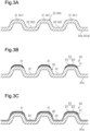
- a film 50 is arranged on the part of the first surface 35 corresponding to the top surface of each first projection 31 that abuts the membrane electrode assembly 11.
- the film 50 includes a first layer 51 applied to the top surface of the first projection 31 and a second layer 52 applied to the upper surface of the first layer 51.
- the film 50 is not arranged on a portion of the first surface 35 of the first separator 30 other than the part corresponding to the top surface of the first projection 31. Instead, the base 30a is exposed at the part on which the film 50 is not arranged.
- the portion where the base 30a is exposed is hereinafter referred to as an exposed portion 36.
- the surface (lower surface in Figs. 1 and 2 ) of the second separator 40 opposed to the membrane electrode assembly 11 defines a second surface 45.
- a film 60 is arranged on the second surface 45.
- the film 60 includes a first layer 61 applied to the entire second surface 45 and a second layer 62 applied to the upper surface of the first layer 61.
- the first layers 51 and 61 include conductive particles made of titanium nitride and binder made of epoxy plastic.
- the second layers 52 and 62 include graphite particles and binder made of polyvinylidene difluoride (PVDF) plastic.
- PVDF polyvinylidene difluoride
- Polyvinylidene difluoride is a thermoplastic
- epoxy plastic is a thermosetting plastic. The thermosetting temperature of epoxy plastic is lower than the melting point of a polyvinylidene difluoride plastic.
- the first separator 30 and the second separator 40 which are adjacent to each other in the laminating direction L of the single cells 10, are joined to each other through laser welding.
- the unit of the first separator 30 and the second separator 40 joined to each other is hereinafter referred to as a separator assembly 20.
- the separator assembly 20 includes a joined portion 21 formed by joining the bottom of each first recess 32 of the first separator 30 and the bottom of each second recess 42 of the second separator 40 to each other through laser welding.
- the joined portion 21 is formed by irradiating, with laser, a part of the exposed portion 36 of the first separator 30 corresponding to the bottom of each first recess 32.
- the joined portion 21, which is a nugget, does not reach the second surface 45 of the second separator 40.
- a press die (not shown) is used to press the base 30a of the first separator 30 to form the first projections 31 and the first recesses 32 on the base 30a.
- the second projections 41 and the second recesses 42 are formed on the base 40a of the second separator 40.
- the first layer 51 is applied to the part of the first surface 35 of the base 30a that abuts the membrane electrode assembly 11, that is, the top surface of each first projection 31.
- the second layer 52 is applied to the upper surface of the first layer 51.
- the first layer 51 and the second layer 52 are thermocompression-bonded to the base 30a. In this manner, the first separator 30 is manufactured.
- the first layer 61 is applied to the entire second surface 45 of the base 40a.
- the second layer 62 is applied to the upper surface of the part of the first layer 61 corresponding to the top surface of each second projection 41.
- the first layer 61 and the second layer 62 are thermocompression-bonded to the base 40a. In this manner, the second separator 40 is manufactured.
- the back surface of the first separator 30 located on the opposite side from the first surface 35 and the back surface of the second separator 40 located on the opposite side from the second surface 45 are abutted against each other.
- the exposed portion 36 is irradiated with laser from the first separator 30 to perform welding.
- the separator assembly 20 is manufactured by joining the first separator 30 to the second separator 40.
- the cathode side of the membrane electrode assembly 11 When the fuel cell is running, the cathode side of the membrane electrode assembly 11 has a higher potential than the anode side. Thus, corrosion resulting from potential difference tends to occur in the second separator 40 located on the cathode side of the membrane electrode assembly 11.
- the film 60 is formed on the entire second surface 45 of the second separator 40. This limits corrosion of the second surface 45 resulting from potential difference.
- the joined portion 21, where the first separator 30 and the second separator 40 are joined to each other, is formed by irradiating the exposed portion 36 of the first separator 30 with laser. This prevents the films 50 and 60 from being irradiated with laser and thus limits the occurrence of weld failure resulting from laser irradiation on the films 50 and 60.
- the film 50 which includes conductive particles, is arranged on the part of the first surface 35 of the first separator 30 configured to abut the membrane electrode assembly 11.
- This structure limits increases in the contact resistance between the membrane electrode assembly 11 and the first separator 30.
- the method for manufacturing the separator assembly 20 for a fuel cell includes a step of forming the film 60, which includes conductive particles, on the entire second surface 45 of the second separator 40, which is intended to be opposed to the membrane electrode assembly 11. This method also includes a step of laser-welding the first separator 30 and the second separator 40 to each other by irradiating the exposed portion 36 of the first separator 30, where the base 30a of the first separator 30 is exposed, with laser.
- titanium nitride of which the first layers 51 and 61 are made instead of titanium nitride of which the first layers 51 and 61 are made, other conductive particles such as titanium carbide or titanium boride may be used.
- the entire first surface 35 may be configured by the exposed portion 36.
- the exposed portion 36 may configure only the part of the first surface 35 of the first separator 30 corresponding to the joined portion 21, and the film 50 may be arranged on a portion other than the exposed portion 36.
- the first surface 35 of the first separator 30 is coated by the film 50 over a broader range. This effectively limits corrosion.
- the material of the base of the first separator and the material of the base of the second separator may be changed to different metal materials other than stainless steel.
- the metal materials include, for example, pure titanium, titanium alloy, aluminum alloy, and magnesium alloy.
Landscapes
- Chemical & Material Sciences (AREA)
- Life Sciences & Earth Sciences (AREA)
- Engineering & Computer Science (AREA)
- Manufacturing & Machinery (AREA)
- Sustainable Development (AREA)
- Sustainable Energy (AREA)
- Chemical Kinetics & Catalysis (AREA)
- Electrochemistry (AREA)
- General Chemical & Material Sciences (AREA)
- Composite Materials (AREA)
- Fuel Cell (AREA)
Claims (2)
- Separatoranordnung (20) für eine Brennstoffzelle, die auf einen Brennstoffzellenstapel appliziert wird, der durch einzelne Zellen (10) gebildet ist, die in einer Laminierrichtung (L) laminiert sind, wobei jede der einzelnen Zellen (10) eine Membranelektrodenanordnung (11), einen ersten Separator (30) mit einer Basis (30a), die aus einer Metallplatte hergestellt und auf einer Anodenseite der Membranelektrodenanordnung (11) angeordnet ist, und einen zweiten Separator (40) mit einer Basis (40a), die aus einer Metallplatte hergestellt ist und auf einer Kathodenseite der Membranelektrodenanordnung (11) angeordnet ist, enthält, wobei die Separatoranordnung umfasst:den ersten Separator (30),den zweiten Separator (40), wobei der erste Separator (30) und der zweite Separator (40) in der Laminierrichtung (L) benachbart sind, undeinen verbundenen Teil (21), wo der erste Separator (30) und der zweite Separator (40) durch Laserschweißen miteinander verbunden sind, wobeider erste Separator (30) erste Vorsprünge (31) und erste Aussparungen (32) enthält, die sich beide erstrecken, wobei die ersten Vorsprünge (31) und die ersten Aussparungen (32) abwechselnd angeordnet sind,der zweite Separator (40) zweite Vorsprünge (41) und zweite Aussparungen (42) enthält, die sich beide erstrecken, wobei die zweiten Vorsprünge (41) und die zweiten Aussparungen (42) abwechselnd angeordnet sind,der erste Separator (30) eine erste Oberfläche (35) und eine Rückseitenoberfläche, die sich auf der entgegengesetzten Seite von der ersten Oberfläche (35) befindet, enthält, wobei die erste Oberfläche (35) dazu bestimmt ist, der Membranelektrodenanordnung (11) gegenüberzuliegen,ein Film (50), der leitende Teilchen enthält, auf einem Teil der ersten Oberfläche (35) des ersten Separators (30) angeordnet ist, der einer oberen Oberfläche eines jeden ersten Vorsprungs (31) entspricht, wobeider Teil der ersten Oberfläche (35), der der oberen Oberfläche eines jeden ersten Vorsprungs (31) entspricht, dazu ausgebildet ist, an der Membranelektrodenanordnung (11) anzuliegen, undein anderer Teil der ersten Oberfläche (35) als der Teil, der der oberen Oberfläche eines jeden ersten Vorsprungs (31) entspricht, ein freiliegender Teil (36) ist, in dem der Film (50) nicht angeordnet ist und die Basis (30a) des ersten Separators (30) freiliegt,der zweite Separator (40) eine zweite Oberfläche (45) und eine Rückseitenoberfläche, die sich auf der entgegengesetzten Seite von der zweiten Oberfläche (45) befindet, enthält, wobei die zweite Oberfläche (45) dazu bestimmt ist, der Membranelektrodenanordnung (11) gegenüberzuliegen,ein Film (60), der leitende Partikel enthält, auf der gesamten zweiten Oberfläche (45) des zweiten Separators (40) angeordnet ist,der erste Separator (30) und der zweite Separator (40) so angeordnet sind, dass Teile der Rückseitenoberfläche des ersten Separators (30), die den Böden der ersten Aussparungen (32) entsprechen, und Teile der Rückseitenoberfläche des zweiten Separators (40), die den Böden der zweiten Aussparungen (42) entsprechen, aneinander anliegen, undder verbundene Teil (21) gebildet wird, indem ein Teil des freiliegenden Teils (36) der ersten Oberfläche (35) des ersten Separators (30), der dem Boden einer jeden ersten Aussparung (32) entspricht, mit Laser bestrahlt wird.
- Verfahren zur Herstellung einer Separatoranordnung (20) für eine Brennstoffzelle, die auf einen Brennstoffzellenstapel appliziert wird, der durch einzelne Zellen (10), die in einer Laminierungsrichtung (L) laminiert sind, gebildet wird, wobei jede der einzelnen Zellen (10) eine Membranelektrodenanordnung (11), einen ersten Separator (30), der eine Basis (30a) aus einer Metallplatte aufweist und auf einer Anodenseite der Membranelektrodenanordnung (11) angeordnet ist, und einen zweiten Separator (40), der mit eine Basis (40a) aus einer Metallplatte aufweist und auf einer Kathodenseite der Membranelektrodenanordnung (11) angeordnet ist, enthält, wobei der erste Separator (30) und der zweite Separator (40), die in der Laminierrichtung (L) zueinander benachbart sind, durch Laserschweißen miteinander verbunden werden, wobei das Verfahren aufweist:einen Schritt des Bildens erste Vorsprünge (31) und erster Aussparungen (32) auf der Basis (30a) des ersten Separators (30) derart, dass sich sowohl die ersten Vorsprünge (31) als auch die ersten Aussparungen (32) erstrecken und die ersten Vorsprünge (31) und die ersten Aussparungen (32) abwechselnd angeordnet sind, wobeider erste Separator (30) eine erste Oberfläche (35) und eine Rückseitenoberfläche, die sich auf der gegenüberliegenden Seite der ersten Oberfläche (35) befindet, enthält, wobei die erste Oberfläche (35) dazu bestimmt ist, der Membranelektrodenanordnung (11) gegenüberzuliegen,einen Schritt des Bildens zweiter Vorsprünge (41) und zweiter Aussparungen (42) auf der Basis (40a) des zweiten Separators (40), so dass sich sowohl die zweiten Vorsprünge (41) als auch die zweiten Aussparungen (42) erstrecken und die zweiten Vorsprünge (41) und die zweiten Aussparungen (42) abwechselnd angeordnet sind, wobeider zweite Separator (40) eine zweite Oberfläche (45) und eine Rückseitenoberfläche, die sich auf der gegenüberliegenden Seite der zweiten Oberfläche (45) befindet, enthält, wobei die zweite Oberfläche (45) dazu bestimmt ist, der Membranelektrodenanordnung (11) gegenüberzuliegen,einen Schritt des Bildens eines Films (50), der leitende Teilchen enthält, auf einem Teil der ersten Oberfläche (35) des ersten Separators (30), der einer oberen Oberfläche eines jeden ersten Vorsprungs (31) entspricht, wobeider Teil der ersten Oberfläche (35), der der oberen Oberfläche jedes ersten Vorsprungs (31) entspricht, dazu ausgebildet ist, an der Membranelektrodenanordnung (11) anzuliegen, undein anderer Teil der ersten Oberfläche (35) als der Teil, der der oberen Oberfläche eines jeden ersten Vorsprungs (31) entspricht, ein freiliegender Teil (36) ist, wo der Film (50) nicht angeordnet ist und die Basis (30a) des ersten Separators (30) freiliegt,einen Schritt des Bildens eines Films (60), der leitende Partikel enthält, auf der gesamten zweiten Oberfläche (45) des zweiten Separators (40), undeinen Schritt des Laserschweißens des ersten Separators (30) und des zweiten Separators (40) aneinander durch Bestrahlen eines Teils des freiliegenden Abschnitts (36) der ersten Oberfläche (35) des ersten Separators (30), der einem Boden einer jeden ersten Aussparung (32) entspricht, mit einem Laser in einem Zustand, in dem Teile der Rückseitenoberfläche des ersten Separators (30), die den Böden der ersten Aussparungen (32) entsprechen, und Teile der Rückseitenoberfläche des zweiten Separators (40), die den Böden der zweiten Aussparungen (42) entsprechen, aneinander anliegen.
Applications Claiming Priority (1)
| Application Number | Priority Date | Filing Date | Title |
|---|---|---|---|
| JP2018045720A JP7010077B2 (ja) | 2018-03-13 | 2018-03-13 | 燃料電池のセパレータ接合体及び燃料電池のセパレータ接合体の製造方法 |
Publications (2)
| Publication Number | Publication Date |
|---|---|
| EP3540839A1 EP3540839A1 (de) | 2019-09-18 |
| EP3540839B1 true EP3540839B1 (de) | 2023-08-30 |
Family
ID=65685225
Family Applications (1)
| Application Number | Title | Priority Date | Filing Date |
|---|---|---|---|
| EP19160471.9A Active EP3540839B1 (de) | 2018-03-13 | 2019-03-04 | Separatoranordnung für brennstoffzelle und verfahren zur herstellung einer separatoranordnung für brennstoffzelle |
Country Status (4)
| Country | Link |
|---|---|
| US (1) | US10897049B2 (de) |
| EP (1) | EP3540839B1 (de) |
| JP (1) | JP7010077B2 (de) |
| CN (1) | CN110277566B (de) |
Families Citing this family (4)
| Publication number | Priority date | Publication date | Assignee | Title |
|---|---|---|---|---|
| JP7247864B2 (ja) * | 2019-11-11 | 2023-03-29 | トヨタ車体株式会社 | 燃料電池用セパレータ、燃料電池用セパレータの製造方法、及び熱転写用シートの製造方法 |
| DE102019135785A1 (de) * | 2019-12-23 | 2021-06-24 | Elringklinger Ag | Verfahren zum Herstellen einer mehrlagigen Bipolarplatte für eine elektrochemische Vorrichtung und Bipolarplatte für eine elektrochemische Vorrichtung |
| WO2022219791A1 (ja) * | 2021-04-15 | 2022-10-20 | 日産自動車株式会社 | 燃料電池および燃料電池の製造方法 |
| JP7613315B2 (ja) * | 2021-08-10 | 2025-01-15 | トヨタ紡織株式会社 | 燃料電池用のセパレータ及び燃料電池の単セル |
Citations (1)
| Publication number | Priority date | Publication date | Assignee | Title |
|---|---|---|---|---|
| US20090117431A1 (en) * | 2006-05-16 | 2009-05-07 | Nissan Motor Co., Ltd. | Fuel cell, fuel cell stack and method of manufacturing the same |
Family Cites Families (9)
| Publication number | Priority date | Publication date | Assignee | Title |
|---|---|---|---|---|
| JP2000106215A (ja) | 1998-09-30 | 2000-04-11 | Japan Storage Battery Co Ltd | 非水電解質電池 |
| US7009136B2 (en) * | 2002-10-09 | 2006-03-07 | General Motors Corporation | Method of fabricating a bipolar plate assembly |
| JP2005285465A (ja) | 2004-03-29 | 2005-10-13 | Nissan Motor Co Ltd | 燃料電池用セパレータ、燃料電池スタック、燃料電池車両、及び燃料電池用セパレータの製造方法 |
| US8089027B2 (en) * | 2004-05-11 | 2012-01-03 | GM Global Technology Operations LLC | Laser welding of conductive coated metallic bipolar plates |
| JP2007073422A (ja) * | 2005-09-08 | 2007-03-22 | Nissan Motor Co Ltd | 燃料電池スタック、及び燃料電池用セパレータの製造方法 |
| JP5343307B2 (ja) | 2006-05-16 | 2013-11-13 | 日産自動車株式会社 | 燃料電池スタックおよび燃料電池セパレータ並びにその製造方法 |
| US8835079B2 (en) * | 2007-06-08 | 2014-09-16 | GM Global Technology Operations LLC | Fuel cell separator plate surface treatment by laser ablation |
| EP3096381B1 (de) * | 2014-01-15 | 2018-10-24 | NGK Spark Plug Co., Ltd. | Brennstoffzellenkassette und brennstoffzellenstapel |
| DE102016208579B3 (de) | 2016-05-19 | 2017-08-31 | Zf Friedrichshafen Ag | Verfahren zur Herstellung eines Fahrzeugbauteils |
-
2018
- 2018-03-13 JP JP2018045720A patent/JP7010077B2/ja active Active
-
2019
- 2019-03-04 EP EP19160471.9A patent/EP3540839B1/de active Active
- 2019-03-07 CN CN201910173340.7A patent/CN110277566B/zh active Active
- 2019-03-07 US US16/296,184 patent/US10897049B2/en active Active
Patent Citations (1)
| Publication number | Priority date | Publication date | Assignee | Title |
|---|---|---|---|---|
| US20090117431A1 (en) * | 2006-05-16 | 2009-05-07 | Nissan Motor Co., Ltd. | Fuel cell, fuel cell stack and method of manufacturing the same |
Also Published As
| Publication number | Publication date |
|---|---|
| CN110277566B (zh) | 2023-08-22 |
| EP3540839A1 (de) | 2019-09-18 |
| CN110277566A (zh) | 2019-09-24 |
| JP2019160558A (ja) | 2019-09-19 |
| JP7010077B2 (ja) | 2022-02-10 |
| US10897049B2 (en) | 2021-01-19 |
| US20190288299A1 (en) | 2019-09-19 |
Similar Documents
| Publication | Publication Date | Title |
|---|---|---|
| EP3540839B1 (de) | Separatoranordnung für brennstoffzelle und verfahren zur herstellung einer separatoranordnung für brennstoffzelle | |
| US11133514B2 (en) | Resin frame equipped membrane electrode assembly and method of producing the same | |
| JPWO2006016441A1 (ja) | 異金属薄板の溶接方法、異金属薄板接合体、電気デバイスおよび電気デバイス集合体 | |
| US20190273268A1 (en) | Frame equipped membrane electrode assembly, method of producing the frame equipped membrane electrode assembly, and fuel cell | |
| JP2023538306A5 (de) | ||
| US12424608B2 (en) | Method and device for producing a component for a battery cell and such a component | |
| EP3799174B1 (de) | Brennstoffzellenseparator und verfahren zur herstellung des brennstoffzellenseparators | |
| US11374240B2 (en) | Fuel-cell unit cell | |
| EP3075020B1 (de) | Verfahren zur herstellung einer membranelektrodenanordnung mit verstärkungen | |
| US11648625B2 (en) | Method using a laser for welding between two metallic materials or for sintering of powder(s), application for making bipolar plates for PEM fuel cells | |
| JP5012395B2 (ja) | 燃料電池用セパレータ及び燃料電池用セパレータの製造方法 | |
| US7335434B2 (en) | Fuel cell separator assembly with diffusion layer, manufacturing method therefor, fuel cell unit, and fuel cell stack | |
| US20210091356A1 (en) | Manufacturing method of fuel cell | |
| JP4073750B2 (ja) | 拡散層セパレータ接合体の製造方法 | |
| JP2004139827A (ja) | 拡散層セパレータ接合体とその製造方法、および燃料電池、燃料電池スタック | |
| JP2021118101A (ja) | 燃料電池スタックの単セルの接着構造、及び燃料電池スタックの単セル用の接着シート | |
| JP2009064734A (ja) | 燃料電池用金属セパレータ、燃料電池スタック、および燃料電池用金属セパレータの製造方法 | |
| EP4456208A1 (de) | Festoxidbrennstoffbatterie | |
| US12431512B2 (en) | Fuel cell separator | |
| JP4880995B2 (ja) | 燃料電池モジュール及び燃料電池スタック | |
| JP2021136205A (ja) | 燃料電池の製造方法 | |
| US20210083312A1 (en) | Fuel cell stack, terminal structure for fuel cell stack, and method of producing terminal structure for fuel cell stack | |
| JP2007115445A (ja) | 燃料電池 | |
| JP2008142722A (ja) | 金属薄板と金属箔の抵抗溶接方法およびこれを用いた非水系二次電池の製造方法 | |
| JP2020068140A (ja) | 燃料電池用セパレータの製造方法 |
Legal Events
| Date | Code | Title | Description |
|---|---|---|---|
| PUAI | Public reference made under article 153(3) epc to a published international application that has entered the european phase |
Free format text: ORIGINAL CODE: 0009012 |
|
| STAA | Information on the status of an ep patent application or granted ep patent |
Free format text: STATUS: REQUEST FOR EXAMINATION WAS MADE |
|
| 17P | Request for examination filed |
Effective date: 20190307 |
|
| AK | Designated contracting states |
Kind code of ref document: A1 Designated state(s): AL AT BE BG CH CY CZ DE DK EE ES FI FR GB GR HR HU IE IS IT LI LT LU LV MC MK MT NL NO PL PT RO RS SE SI SK SM TR |
|
| AX | Request for extension of the european patent |
Extension state: BA ME |
|
| RIC1 | Information provided on ipc code assigned before grant |
Ipc: H01M 8/10 20160101ALI20220502BHEP Ipc: H01M 8/0206 20160101ALI20220502BHEP Ipc: H01M 8/0297 20160101ALI20220502BHEP Ipc: H01M 8/0254 20160101ALI20220502BHEP Ipc: H01M 8/0228 20160101AFI20220502BHEP |
|
| GRAP | Despatch of communication of intention to grant a patent |
Free format text: ORIGINAL CODE: EPIDOSNIGR1 |
|
| STAA | Information on the status of an ep patent application or granted ep patent |
Free format text: STATUS: GRANT OF PATENT IS INTENDED |
|
| INTG | Intention to grant announced |
Effective date: 20220711 |
|
| GRAJ | Information related to disapproval of communication of intention to grant by the applicant or resumption of examination proceedings by the epo deleted |
Free format text: ORIGINAL CODE: EPIDOSDIGR1 |
|
| STAA | Information on the status of an ep patent application or granted ep patent |
Free format text: STATUS: REQUEST FOR EXAMINATION WAS MADE |
|
| INTC | Intention to grant announced (deleted) | ||
| GRAP | Despatch of communication of intention to grant a patent |
Free format text: ORIGINAL CODE: EPIDOSNIGR1 |
|
| STAA | Information on the status of an ep patent application or granted ep patent |
Free format text: STATUS: GRANT OF PATENT IS INTENDED |
|
| INTG | Intention to grant announced |
Effective date: 20230404 |
|
| GRAS | Grant fee paid |
Free format text: ORIGINAL CODE: EPIDOSNIGR3 |
|
| GRAA | (expected) grant |
Free format text: ORIGINAL CODE: 0009210 |
|
| STAA | Information on the status of an ep patent application or granted ep patent |
Free format text: STATUS: THE PATENT HAS BEEN GRANTED |
|
| AK | Designated contracting states |
Kind code of ref document: B1 Designated state(s): AL AT BE BG CH CY CZ DE DK EE ES FI FR GB GR HR HU IE IS IT LI LT LU LV MC MK MT NL NO PL PT RO RS SE SI SK SM TR |
|
| REG | Reference to a national code |
Ref country code: GB Ref legal event code: FG4D |
|
| REG | Reference to a national code |
Ref country code: CH Ref legal event code: EP |
|
| REG | Reference to a national code |
Ref country code: DE Ref legal event code: R096 Ref document number: 602019035923 Country of ref document: DE |
|
| REG | Reference to a national code |
Ref country code: IE Ref legal event code: FG4D |
|
| REG | Reference to a national code |
Ref country code: LT Ref legal event code: MG9D |
|
| REG | Reference to a national code |
Ref country code: NL Ref legal event code: MP Effective date: 20230830 |
|
| REG | Reference to a national code |
Ref country code: AT Ref legal event code: MK05 Ref document number: 1606590 Country of ref document: AT Kind code of ref document: T Effective date: 20230830 |
|
| PG25 | Lapsed in a contracting state [announced via postgrant information from national office to epo] |
Ref country code: GR Free format text: LAPSE BECAUSE OF FAILURE TO SUBMIT A TRANSLATION OF THE DESCRIPTION OR TO PAY THE FEE WITHIN THE PRESCRIBED TIME-LIMIT Effective date: 20231201 |
|
| PG25 | Lapsed in a contracting state [announced via postgrant information from national office to epo] |
Ref country code: IS Free format text: LAPSE BECAUSE OF FAILURE TO SUBMIT A TRANSLATION OF THE DESCRIPTION OR TO PAY THE FEE WITHIN THE PRESCRIBED TIME-LIMIT Effective date: 20231230 |
|
| PG25 | Lapsed in a contracting state [announced via postgrant information from national office to epo] |
Ref country code: SE Free format text: LAPSE BECAUSE OF FAILURE TO SUBMIT A TRANSLATION OF THE DESCRIPTION OR TO PAY THE FEE WITHIN THE PRESCRIBED TIME-LIMIT Effective date: 20230830 Ref country code: RS Free format text: LAPSE BECAUSE OF FAILURE TO SUBMIT A TRANSLATION OF THE DESCRIPTION OR TO PAY THE FEE WITHIN THE PRESCRIBED TIME-LIMIT Effective date: 20230830 Ref country code: NO Free format text: LAPSE BECAUSE OF FAILURE TO SUBMIT A TRANSLATION OF THE DESCRIPTION OR TO PAY THE FEE WITHIN THE PRESCRIBED TIME-LIMIT Effective date: 20231130 Ref country code: LV Free format text: LAPSE BECAUSE OF FAILURE TO SUBMIT A TRANSLATION OF THE DESCRIPTION OR TO PAY THE FEE WITHIN THE PRESCRIBED TIME-LIMIT Effective date: 20230830 Ref country code: LT Free format text: LAPSE BECAUSE OF FAILURE TO SUBMIT A TRANSLATION OF THE DESCRIPTION OR TO PAY THE FEE WITHIN THE PRESCRIBED TIME-LIMIT Effective date: 20230830 Ref country code: IS Free format text: LAPSE BECAUSE OF FAILURE TO SUBMIT A TRANSLATION OF THE DESCRIPTION OR TO PAY THE FEE WITHIN THE PRESCRIBED TIME-LIMIT Effective date: 20231230 Ref country code: HR Free format text: LAPSE BECAUSE OF FAILURE TO SUBMIT A TRANSLATION OF THE DESCRIPTION OR TO PAY THE FEE WITHIN THE PRESCRIBED TIME-LIMIT Effective date: 20230830 Ref country code: GR Free format text: LAPSE BECAUSE OF FAILURE TO SUBMIT A TRANSLATION OF THE DESCRIPTION OR TO PAY THE FEE WITHIN THE PRESCRIBED TIME-LIMIT Effective date: 20231201 Ref country code: FI Free format text: LAPSE BECAUSE OF FAILURE TO SUBMIT A TRANSLATION OF THE DESCRIPTION OR TO PAY THE FEE WITHIN THE PRESCRIBED TIME-LIMIT Effective date: 20230830 Ref country code: AT Free format text: LAPSE BECAUSE OF FAILURE TO SUBMIT A TRANSLATION OF THE DESCRIPTION OR TO PAY THE FEE WITHIN THE PRESCRIBED TIME-LIMIT Effective date: 20230830 |
|
| PG25 | Lapsed in a contracting state [announced via postgrant information from national office to epo] |
Ref country code: PL Free format text: LAPSE BECAUSE OF FAILURE TO SUBMIT A TRANSLATION OF THE DESCRIPTION OR TO PAY THE FEE WITHIN THE PRESCRIBED TIME-LIMIT Effective date: 20230830 Ref country code: NL Free format text: LAPSE BECAUSE OF FAILURE TO SUBMIT A TRANSLATION OF THE DESCRIPTION OR TO PAY THE FEE WITHIN THE PRESCRIBED TIME-LIMIT Effective date: 20230830 |
|
| PG25 | Lapsed in a contracting state [announced via postgrant information from national office to epo] |
Ref country code: ES Free format text: LAPSE BECAUSE OF FAILURE TO SUBMIT A TRANSLATION OF THE DESCRIPTION OR TO PAY THE FEE WITHIN THE PRESCRIBED TIME-LIMIT Effective date: 20230830 |
|
| PG25 | Lapsed in a contracting state [announced via postgrant information from national office to epo] |
Ref country code: SM Free format text: LAPSE BECAUSE OF FAILURE TO SUBMIT A TRANSLATION OF THE DESCRIPTION OR TO PAY THE FEE WITHIN THE PRESCRIBED TIME-LIMIT Effective date: 20230830 Ref country code: RO Free format text: LAPSE BECAUSE OF FAILURE TO SUBMIT A TRANSLATION OF THE DESCRIPTION OR TO PAY THE FEE WITHIN THE PRESCRIBED TIME-LIMIT Effective date: 20230830 Ref country code: ES Free format text: LAPSE BECAUSE OF FAILURE TO SUBMIT A TRANSLATION OF THE DESCRIPTION OR TO PAY THE FEE WITHIN THE PRESCRIBED TIME-LIMIT Effective date: 20230830 Ref country code: EE Free format text: LAPSE BECAUSE OF FAILURE TO SUBMIT A TRANSLATION OF THE DESCRIPTION OR TO PAY THE FEE WITHIN THE PRESCRIBED TIME-LIMIT Effective date: 20230830 Ref country code: DK Free format text: LAPSE BECAUSE OF FAILURE TO SUBMIT A TRANSLATION OF THE DESCRIPTION OR TO PAY THE FEE WITHIN THE PRESCRIBED TIME-LIMIT Effective date: 20230830 Ref country code: CZ Free format text: LAPSE BECAUSE OF FAILURE TO SUBMIT A TRANSLATION OF THE DESCRIPTION OR TO PAY THE FEE WITHIN THE PRESCRIBED TIME-LIMIT Effective date: 20230830 Ref country code: SK Free format text: LAPSE BECAUSE OF FAILURE TO SUBMIT A TRANSLATION OF THE DESCRIPTION OR TO PAY THE FEE WITHIN THE PRESCRIBED TIME-LIMIT Effective date: 20230830 Ref country code: PT Free format text: LAPSE BECAUSE OF FAILURE TO SUBMIT A TRANSLATION OF THE DESCRIPTION OR TO PAY THE FEE WITHIN THE PRESCRIBED TIME-LIMIT Effective date: 20240102 |
|
| PG25 | Lapsed in a contracting state [announced via postgrant information from national office to epo] |
Ref country code: IT Free format text: LAPSE BECAUSE OF FAILURE TO SUBMIT A TRANSLATION OF THE DESCRIPTION OR TO PAY THE FEE WITHIN THE PRESCRIBED TIME-LIMIT Effective date: 20230830 |
|
| REG | Reference to a national code |
Ref country code: DE Ref legal event code: R097 Ref document number: 602019035923 Country of ref document: DE |
|
| PLBE | No opposition filed within time limit |
Free format text: ORIGINAL CODE: 0009261 |
|
| STAA | Information on the status of an ep patent application or granted ep patent |
Free format text: STATUS: NO OPPOSITION FILED WITHIN TIME LIMIT |
|
| PG25 | Lapsed in a contracting state [announced via postgrant information from national office to epo] |
Ref country code: SI Free format text: LAPSE BECAUSE OF FAILURE TO SUBMIT A TRANSLATION OF THE DESCRIPTION OR TO PAY THE FEE WITHIN THE PRESCRIBED TIME-LIMIT Effective date: 20230830 |
|
| 26N | No opposition filed |
Effective date: 20240603 |
|
| REG | Reference to a national code |
Ref country code: CH Ref legal event code: PL |
|
| PG25 | Lapsed in a contracting state [announced via postgrant information from national office to epo] |
Ref country code: BG Free format text: LAPSE BECAUSE OF FAILURE TO SUBMIT A TRANSLATION OF THE DESCRIPTION OR TO PAY THE FEE WITHIN THE PRESCRIBED TIME-LIMIT Effective date: 20230830 |
|
| PG25 | Lapsed in a contracting state [announced via postgrant information from national office to epo] |
Ref country code: LU Free format text: LAPSE BECAUSE OF NON-PAYMENT OF DUE FEES Effective date: 20240304 |
|
| PG25 | Lapsed in a contracting state [announced via postgrant information from national office to epo] |
Ref country code: MC Free format text: LAPSE BECAUSE OF FAILURE TO SUBMIT A TRANSLATION OF THE DESCRIPTION OR TO PAY THE FEE WITHIN THE PRESCRIBED TIME-LIMIT Effective date: 20230830 |
|
| GBPC | Gb: european patent ceased through non-payment of renewal fee |
Effective date: 20240304 |
|
| PG25 | Lapsed in a contracting state [announced via postgrant information from national office to epo] |
Ref country code: MC Free format text: LAPSE BECAUSE OF FAILURE TO SUBMIT A TRANSLATION OF THE DESCRIPTION OR TO PAY THE FEE WITHIN THE PRESCRIBED TIME-LIMIT Effective date: 20230830 Ref country code: LU Free format text: LAPSE BECAUSE OF NON-PAYMENT OF DUE FEES Effective date: 20240304 Ref country code: BG Free format text: LAPSE BECAUSE OF FAILURE TO SUBMIT A TRANSLATION OF THE DESCRIPTION OR TO PAY THE FEE WITHIN THE PRESCRIBED TIME-LIMIT Effective date: 20230830 |
|
| REG | Reference to a national code |
Ref country code: BE Ref legal event code: MM Effective date: 20240331 |
|
| PG25 | Lapsed in a contracting state [announced via postgrant information from national office to epo] |
Ref country code: BE Free format text: LAPSE BECAUSE OF NON-PAYMENT OF DUE FEES Effective date: 20240331 |
|
| PG25 | Lapsed in a contracting state [announced via postgrant information from national office to epo] |
Ref country code: GB Free format text: LAPSE BECAUSE OF NON-PAYMENT OF DUE FEES Effective date: 20240304 |
|
| PG25 | Lapsed in a contracting state [announced via postgrant information from national office to epo] |
Ref country code: IE Free format text: LAPSE BECAUSE OF NON-PAYMENT OF DUE FEES Effective date: 20240304 |
|
| PG25 | Lapsed in a contracting state [announced via postgrant information from national office to epo] |
Ref country code: IE Free format text: LAPSE BECAUSE OF NON-PAYMENT OF DUE FEES Effective date: 20240304 Ref country code: GB Free format text: LAPSE BECAUSE OF NON-PAYMENT OF DUE FEES Effective date: 20240304 Ref country code: BE Free format text: LAPSE BECAUSE OF NON-PAYMENT OF DUE FEES Effective date: 20240331 Ref country code: CH Free format text: LAPSE BECAUSE OF NON-PAYMENT OF DUE FEES Effective date: 20240331 |
|
| PG25 | Lapsed in a contracting state [announced via postgrant information from national office to epo] |
Ref country code: CY Free format text: LAPSE BECAUSE OF FAILURE TO SUBMIT A TRANSLATION OF THE DESCRIPTION OR TO PAY THE FEE WITHIN THE PRESCRIBED TIME-LIMIT; INVALID AB INITIO Effective date: 20190304 |
|
| PG25 | Lapsed in a contracting state [announced via postgrant information from national office to epo] |
Ref country code: HU Free format text: LAPSE BECAUSE OF FAILURE TO SUBMIT A TRANSLATION OF THE DESCRIPTION OR TO PAY THE FEE WITHIN THE PRESCRIBED TIME-LIMIT; INVALID AB INITIO Effective date: 20190304 |
|
| PG25 | Lapsed in a contracting state [announced via postgrant information from national office to epo] |
Ref country code: TR Free format text: LAPSE BECAUSE OF FAILURE TO SUBMIT A TRANSLATION OF THE DESCRIPTION OR TO PAY THE FEE WITHIN THE PRESCRIBED TIME-LIMIT Effective date: 20230830 |
|
| PGFP | Annual fee paid to national office [announced via postgrant information from national office to epo] |
Ref country code: DE Payment date: 20260128 Year of fee payment: 8 |
|
| PGFP | Annual fee paid to national office [announced via postgrant information from national office to epo] |
Ref country code: FR Payment date: 20260209 Year of fee payment: 8 |