EP3540747B1 - Bistabiles elektromagnet mit einem zwischenzustand - Google Patents
Bistabiles elektromagnet mit einem zwischenzustand Download PDFInfo
- Publication number
- EP3540747B1 EP3540747B1 EP19275029.7A EP19275029A EP3540747B1 EP 3540747 B1 EP3540747 B1 EP 3540747B1 EP 19275029 A EP19275029 A EP 19275029A EP 3540747 B1 EP3540747 B1 EP 3540747B1
- Authority
- EP
- European Patent Office
- Prior art keywords
- armature
- pin
- pole piece
- housing
- spring
- Prior art date
- Legal status (The legal status is an assumption and is not a legal conclusion. Google has not performed a legal analysis and makes no representation as to the accuracy of the status listed.)
- Active
Links
- XEEYBQQBJWHFJM-UHFFFAOYSA-N Iron Chemical compound [Fe] XEEYBQQBJWHFJM-UHFFFAOYSA-N 0.000 description 6
- PXHVJJICTQNCMI-UHFFFAOYSA-N Nickel Chemical compound [Ni] PXHVJJICTQNCMI-UHFFFAOYSA-N 0.000 description 6
- 229910000831 Steel Inorganic materials 0.000 description 3
- 229910052742 iron Inorganic materials 0.000 description 3
- 239000000696 magnetic material Substances 0.000 description 3
- 229910052759 nickel Inorganic materials 0.000 description 3
- 239000010959 steel Substances 0.000 description 3
- 230000004907 flux Effects 0.000 description 2
- 230000005540 biological transmission Effects 0.000 description 1
- 230000006835 compression Effects 0.000 description 1
- 238000007906 compression Methods 0.000 description 1
- 238000006073 displacement reaction Methods 0.000 description 1
- 230000003993 interaction Effects 0.000 description 1
Images


Classifications
-
- H—ELECTRICITY
- H01—ELECTRIC ELEMENTS
- H01F—MAGNETS; INDUCTANCES; TRANSFORMERS; SELECTION OF MATERIALS FOR THEIR MAGNETIC PROPERTIES
- H01F7/00—Magnets
- H01F7/06—Electromagnets; Actuators including electromagnets
- H01F7/08—Electromagnets; Actuators including electromagnets with armatures
- H01F7/121—Guiding or setting position of armatures, e.g. retaining armatures in their end position
- H01F7/122—Guiding or setting position of armatures, e.g. retaining armatures in their end position by permanent magnets
-
- H—ELECTRICITY
- H01—ELECTRIC ELEMENTS
- H01F—MAGNETS; INDUCTANCES; TRANSFORMERS; SELECTION OF MATERIALS FOR THEIR MAGNETIC PROPERTIES
- H01F7/00—Magnets
- H01F7/06—Electromagnets; Actuators including electromagnets
- H01F7/08—Electromagnets; Actuators including electromagnets with armatures
- H01F7/16—Rectilinearly-movable armatures
- H01F7/1607—Armatures entering the winding
- H01F7/1615—Armatures or stationary parts of magnetic circuit having permanent magnet
-
- F—MECHANICAL ENGINEERING; LIGHTING; HEATING; WEAPONS; BLASTING
- F16—ENGINEERING ELEMENTS AND UNITS; GENERAL MEASURES FOR PRODUCING AND MAINTAINING EFFECTIVE FUNCTIONING OF MACHINES OR INSTALLATIONS; THERMAL INSULATION IN GENERAL
- F16H—GEARING
- F16H61/00—Control functions within control units of change-speed- or reversing-gearings for conveying rotary motion ; Control of exclusively fluid gearing, friction gearing, gearings with endless flexible members or other particular types of gearing
- F16H61/22—Locking of the control input devices
-
- H—ELECTRICITY
- H01—ELECTRIC ELEMENTS
- H01F—MAGNETS; INDUCTANCES; TRANSFORMERS; SELECTION OF MATERIALS FOR THEIR MAGNETIC PROPERTIES
- H01F7/00—Magnets
- H01F7/02—Permanent magnets [PM]
- H01F7/0205—Magnetic circuits with PM in general
-
- H—ELECTRICITY
- H01—ELECTRIC ELEMENTS
- H01F—MAGNETS; INDUCTANCES; TRANSFORMERS; SELECTION OF MATERIALS FOR THEIR MAGNETIC PROPERTIES
- H01F7/00—Magnets
- H01F7/06—Electromagnets; Actuators including electromagnets
- H01F7/08—Electromagnets; Actuators including electromagnets with armatures
- H01F7/081—Magnetic constructions
-
- H—ELECTRICITY
- H01—ELECTRIC ELEMENTS
- H01F—MAGNETS; INDUCTANCES; TRANSFORMERS; SELECTION OF MATERIALS FOR THEIR MAGNETIC PROPERTIES
- H01F7/00—Magnets
- H01F7/06—Electromagnets; Actuators including electromagnets
- H01F7/08—Electromagnets; Actuators including electromagnets with armatures
- H01F7/16—Rectilinearly-movable armatures
-
- F—MECHANICAL ENGINEERING; LIGHTING; HEATING; WEAPONS; BLASTING
- F16—ENGINEERING ELEMENTS AND UNITS; GENERAL MEASURES FOR PRODUCING AND MAINTAINING EFFECTIVE FUNCTIONING OF MACHINES OR INSTALLATIONS; THERMAL INSULATION IN GENERAL
- F16H—GEARING
- F16H63/00—Control outputs from the control unit to change-speed- or reversing-gearings for conveying rotary motion or to other devices than the final output mechanism
- F16H63/02—Final output mechanisms therefor; Actuating means for the final output mechanisms
- F16H63/30—Constructional features of the final output mechanisms
- F16H63/34—Locking or disabling mechanisms
- F16H63/3416—Parking lock mechanisms or brakes in the transmission
- F16H63/3458—Parking lock mechanisms or brakes in the transmission with electric actuating means, e.g. shift by wire
- F16H63/3475—Parking lock mechanisms or brakes in the transmission with electric actuating means, e.g. shift by wire using solenoids
-
- H—ELECTRICITY
- H01—ELECTRIC ELEMENTS
- H01F—MAGNETS; INDUCTANCES; TRANSFORMERS; SELECTION OF MATERIALS FOR THEIR MAGNETIC PROPERTIES
- H01F7/00—Magnets
- H01F7/06—Electromagnets; Actuators including electromagnets
- H01F7/08—Electromagnets; Actuators including electromagnets with armatures
- H01F7/16—Rectilinearly-movable armatures
- H01F2007/1669—Armatures actuated by current pulse, e.g. bistable actuators
-
- H—ELECTRICITY
- H01—ELECTRIC ELEMENTS
- H01F—MAGNETS; INDUCTANCES; TRANSFORMERS; SELECTION OF MATERIALS FOR THEIR MAGNETIC PROPERTIES
- H01F7/00—Magnets
- H01F7/06—Electromagnets; Actuators including electromagnets
- H01F7/08—Electromagnets; Actuators including electromagnets with armatures
- H01F7/16—Rectilinearly-movable armatures
- H01F2007/1692—Electromagnets or actuators with two coils
-
- H—ELECTRICITY
- H01—ELECTRIC ELEMENTS
- H01F—MAGNETS; INDUCTANCES; TRANSFORMERS; SELECTION OF MATERIALS FOR THEIR MAGNETIC PROPERTIES
- H01F7/00—Magnets
- H01F7/06—Electromagnets; Actuators including electromagnets
- H01F7/08—Electromagnets; Actuators including electromagnets with armatures
- H01F7/127—Assembling
Definitions
- Bi-stable solenoids typically include a wire coil arranged around a moveable armature. When a current is applied to the wire coil, a magnetic field is generated that can then actuate (i.e., move) the moveable armature from a first position to a second position.
- an armature within a bi-stable solenoid is moveable between two stable positions. For example, a current may be applied to the wire coil in a first direction with a magnitude sufficient to actuate an armature from a first position to a second position. The armature may remain in the second position until a current is applied to the wire coil in a second direction with a magnitude sufficient to actuate the armature from the second position back to the first position. Again, the armature may remain in the first position until the current is applied to the wire coil in the first direction with a sufficient magnitude.
- GB1237706 discloses an electromagnet which may operate a small pneumatic valve, comprising a pot magnet with a remnant magnet gripped between a root portion of the core of the electromagnet and pole member, having a pole face and shoulders tapering toward the pole face arranged for co-operation with shoulders of a retaining member which may be part of a coil former.
- the former is held in the pot by a guide ring in an annular top wall of the magnet which has a raised portion surrounding the hollow armature which is biased away from the core by a spring.
- the armature contains one end of an actuating rod guided in the ring.
- a compression spring is biased between the end of the rod and a plug in the end of the armature to enable the armature to start to move downwards before the rod moves.
- US4072918 discloses an actuator having an armature plate urged to a stable position by a spring and which may be held in another stable position by a permanent magnet.
- the application of an appropriate current pulse to a coil within the actuator reduces the flux flow through and the magnetic force on the armature sufficiently to release the armature to the former stable position under the influence of the spring.
- Two magnetic circuits, one of which includes a non-working air gap are employed, the non-working air gap serving to maintain a flux path, of a predetermined maximum reluctance, for the permanent magnet when the armature plate is in the former stable position.
- a spring is biased between the armature and the actuating pin of the actuator in order to absorb impact forces trying to reset the armature.
- the present disclosure provides a bi-stable solenoid that includes an internally disposed spring as defined by independent claim 1, which allows for the bi-stable solenoid to enter a tooth butt, or intermediate position where a pin can engage a tooth of a gear, and remain biased toward an extended position.
- the present invention provides a bi-stable solenoid comprising a housing, a wire coil, a permanent magnet, an armature, a pin, and a spring.
- the wire coil and the permanent magnet are arranged within the housing.
- the armature is slidably arranged within the housing and is moveable between a first armature position and a second armature position.
- the pin at least partially extends out of the housing and is slidably engaged by the armature.
- the spring is biased between the armature and the pin. When the pin encounters an intermediate position between a retracted position and an extended position due to the pin engaging an obstruction, the spring is configured to maintain a biasing force on the pin until the obstruction is removed.
- the present invention provides a bi-stable solenoid comprising a housing, a wire coil arranged within the housing, a permanent magnet arranged within the housing, and an armature slidably arranged within the housing and moveable between a first armature position and a second armature position.
- the bi-stable solenoid further includes a pin at least partially extending out of the housing and slidably engaged by the armature. The pin is moveable between an extended position and a retracted position.
- the bi-stable solenoid further includes a spring that is biased between the armature and the pin.
- the spring When the armature is moved from the first armature position to the second armature position, the spring applies a force onto a pin, thereby biasing the pin toward the extended position, and when the armature is moved from the first armature position to the second armature position and the pin encounters an obstruction, the spring continues to bias the pin toward the extended position until the obstruction is removed and the pin is allowed to move to the extended position.
- Fig. 1 shows a gear system 10 according to one aspect of the present disclosure.
- the gear system 10 can include a housing 12 enveloping a gear 14, one or more of rocker arms 16, and one or more bi-stable solenoids 18.
- the gear system 10 includes a pair of rocker arms 16 and a corresponding pair of bi-stable solenoids 18 configured to actuate the rocker arms 16, as will be described.
- the gear system 10 may be arranged within a transmission on a vehicle.
- the gear system 10 may be arranged in an application requiring selective rotational control of a gear.
- the gear 14 can be rotatably mounted within the housing 12.
- the pair of rocker arms 16 can be rotatably mounted within the housing 12.
- the rocker arms 16 can be configured to engage and disengage the gear 14 to selectively prevent or allow rotation of the gear 14 in either of the clockwise or counter-clockwise directions.
- the pair of bi-stable solenoids 18 each include a pin 22 configured to interact with a corresponding one of the rocker arms 16.
- the pins 22 are each selectively moveable via energization of the corresponding bi-stable solenoid 18. Actuation of the pins 22 can correspondingly actuate the rocker arms 16 to selectively engage and disengage the gear 14.
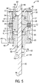
- the bi-stable solenoid 18 includes a housing 24 at least partially enveloping a first pole piece 26, a bobbin 27, a second pole piece 32, a permanent magnet 34, an armature 36, and a spring 37.
- the housing 24 defines a generally hollow cylindrical shape and includes a first surface 38 and a generally open second end 42.
- the housing 24 can be coupled to a mounting flange 44 proximate the open second end 42.
- the mounting flange 44 can at least partially cover the open second end 42, thereby creating an enclosed chamber within the housing 24.
- the mounting flange 44 can be coupled to the housing 12, for example, to fix the bi-stable solenoid 18 relative to the gear 14.
- the first pole piece 26 can be fabricated from a magnetic material (e.g., magnetic steel, iron, nickel, etc.). The first pole piece 26 is disposed at least partially within the housing 24 and extends at least partially through to the first surface 38.
- the first pole piece 26 includes a first armature-receiving portion 46 and a first pin-engaging aperture 48.
- the first armature-receiving portion 46 can be disposed at a first end 47 of the first pole piece 26, and can include a first armature-receiving recess 49 configured to receive the armature 36.
- the first pin-engaging aperture 48 can extend through a second end 50 of the first pole piece 26, and is configured to slidably receive the pin 22 therethrough.
- the bobbin 27 can define a first bobbin portion 28 that can be arranged adjacent to the first surface 38 of the housing 24.
- the first bobbin portion 28 can define a generally annular shape, and can surround at least a portion of the first pole piece 26.
- a first coil bay 54 of a wire coil 55 may be wound around the first bobbin portion 28.
- the second bobbin portion 30 can be arranged adjacent to the mounting flange 44 within the housing 24.
- the second bobbin portion 30 can define a generally annular shape, and can surround at least a portion of the second pole piece 32.
- a second coil bay 66 of the wire coil 55 may be wound around the second bobbin portion 30.
- the second pole piece 32 can be fabricated from a magnetic material (e.g., magnetic steel, iron, nickel, etc.).
- the second pole piece 32 can be disposed partially within the housing 24 and is spaced axially apart from the first pole piece 26.
- the second pole piece 32 can extend at least partially through and be coupled to the mounting flange 44.
- the second pole piece 32 includes a second armature-receiving portion 56, a second pin-engaging aperture 60, and a hollow cylindrical portion 62.
- the second armature-receiving portion 56 can be disposed at a first end 61 of the second pole piece 32, and can include a second armature-receiving recess 63 configured to receive the armature 36.
- the second pin-engaging aperture 60 can extend through a second end 64 of the second pole piece 32, and is configured to slidably receive the pin 22 therethrough.
- the hollow cylindrical portion 62 can extend between the second armature-receiving portion 56 and the second end 64 of the second pole piece 32.
- the permanent magnet 34 can define a generally annular shape and can be disposed within the housing 24 between the second bobbin portion 30 and the first bobbin portion 28.
- the annular shape of the permanent magnet 34 enables the armature 36 to extend therethrough.
- the armature 36 can be fabricated from a magnetic material (e.g., magnetic steel, iron, nickel, etc.).
- the armature 36 can include a first portion 68, a second portion 70, and a central aperture 72.
- the first portion 68 can be configured to engage the first armature-receiving recess 49 of the first pole piece 26, and the second portion 70 can be configured to engage the second armature-receiving recess 63 of the second pole piece 32.
- the second portion 70 of the armature 36 can additionally include a spring-receiving recess 74 configured to engage the spring 37.
- the central aperture 72 is configured to slidably receive the pin 22 therethrough, as will be described herein.
- the pin 22 extends slidably through the first pole piece 26, the armature 36, and the second pole piece 32.
- the pin 22 slidably engages the second pin-engaging aperture 60 of the second pole piece 32, the central aperture 72 of the armature 36, and the first pin-engaging aperture 48 of the first pole piece 26.
- the pin 22 can include a shoulder 76 and a snap ring recess 78 arranged on opposing sides of the armature 36.
- the shoulder 76 can extend radially outward from the pin 22 and can be sized such that an outer diameter of the shoulder 76 is larger than the inner diameter of the central aperture 72.
- the snap ring recess 78 can receive a snap ring 82, which can snap into the snap ring recess 78, thereby fixing the snap ring 82 relative to the pin 22.
- the snap ring 82 can be sized such that an outer diameter of the snap ring 82 is larger than a diameter of the spring 37.
- the snap ring recess 78 can be axially separated from the shoulder 76, such that the armature 36 is arranged between the shoulder 76 and the snap ring 82.
- the bi-stable solenoid 18 may include a second snap ring 80 coupled to the pin 22 on an axially opposing side of the armature 32 (see, e.g., Fig. 5 ) than the snap ring 82, rather than the shoulder 76.
- the bi-stable solenoid 18 may include another shoulder arranged on an axially opposing side of the armature 32 than shoulder 76, rather than the snap ring 82.
- the pin 22 is designed to include mechanical structures on axially opposing sides of the armature 32 to limit the axial displacement of the pin 22 and to provide a structure against which the spring 37 biases the pin 22 relative to the armature 32.
- the spring 37 envelops a portion of the pin 22 between the snap ring 82 and the spring receiving recess 74 of the armature 36.
- the spring 37 is biased between the spring receiving recess 74 and the first snap ring 82.
- the spring 37 biases the pin 22 in an axial direction away from the armature 36 (i.e., in an downward direction from the perspective of Fig. 2 ).
- the described operation of the bi-stable solenoid 18 can be adapted to any system that includes a suitable gear.
- the wire coil 55 of the bi-stable solenoid 18 may be selectively energized, i.e., supplied with a current in a desired direction at a predetermined magnitude.
- the armature 36 moves between two stable positions depending on the direction of the current applied to the wire coil 55.
- the armature 36 is moveable between a first armature position (see, e.g., Fig.
- the armature 36 may be in the first armature position and the wire coil 55 of the bi-stable solenoid 18 may be energized with a current in a first direction.
- the armature 36 may then fully shift (i.e., actuate) to the second armature position and the wire coil 55 may be de-energized (i.e., the current is removed).
- the armature 36 will remain in the second armature position until the wire coil 55 is energized with a current in a second direction opposite to the first direction.
- the armature 36 may then fully shift back to the first armature position and the wire coil 55 may be de-energized. In this way, the operation of the bi-stable solenoid 18 may require a reduced energy input because the wire coil 55 is not required to be continuously energized.
- the movement of the armature 36 may influence a position of the pin 22.
- the pin 22 may be moved between a retracted position (see, e.g., Fig. 2 ) and an extended position (see, e.g., Fig. 3 ), in response to movement of the armature 36 between the first armature position and the second armature position.
- the pin 22 may encounter an intermediate position (see, e.g., Fig. 4 ) where the pin 22 is temporarily prevented from fully extending from the retracted position to the extended position due to an obstruction.
- the design and properties of the bi-stable solenoid 18 enable the pin 22 to encounter the intermediate position and eventually reach the desired extended position without requiring energization of the wire coil 55.
- movement of the pin 22 between the extended position and the retracted position may inhibit or allow the gear 14 to rotate in a desired direction.
- current can be selectively applied to the wire coil 55 to move the pin 22 into the extended position (see, e.g., Fig. 3 ).
- a current in the first direction may be applied to the wire coil 55 to shift the armature 36 to the second armature position.
- the spring 37 is compressed and forces the snap ring 82, and thereby the pin 22, to displace in a first axial direction 98 (e.g., downward from the perspective of Figs. 2 and 3 ).
- the pin 22 can be allowed to displace in the first axial direction 98 until the shoulder 76 engages the armature 36.
- an actuation end 96 of the pin 22 engages the rocker arm 16 and displaces the rocker arm 16 into engagement with a portion of the gear 14. If the rocker arm 16 does not contact one of the gear teeth 86 as the pin 22 displaces to the extended position, the rocker arm 16 is displaced into contact with the gear 14 in a space between adjacent gear teeth 86.
- the rocker arm 16 is configured to prevent the gear 14 from rotating in a given direction. For example, in the illustrated non-limiting example of Fig. 3 , the gear 14 is prevented from rotating in a counter-clockwise direction.
- the rocker arms 16 can be arranged such that one rocker arm 16 selectively prevents rotation of the gear 14 in the clockwise direction (e.g., the rocker arm 16 on the right) and the other rocker arm 16 prevents rotation of the gear 14 in the counter-clockwise direction (e.g., the rocker arm 16 on the left).
- the gear 14 can be prevented rotation in both the clockwise and counter clockwise directions simultaneously.
- a current in the second direction may be applied to the wire coil 55 to shift the armature 36 to the first armature position.
- the armature 36 may displace the pin 22 therewith due to the engagement between the armature 36 and the shoulder 76. That is, the pin 22 can be displaced in a second axial direction 100 (e.g., upward from the perspective of Fig. 2 ) until the armature 36 reaches the second armature position.
- the actuation end 96 of the pin 22 can be displaced away from the gear 14, which allows a rocker arm spring 92 to bias the rocker arm 16 out of engagement with the gear 14 and permits the gear 14 to rotate.
- Fig. 4 in some instances during operation, as the pin 22 is displaced from the retracted position to the extended position, the rocker arm 16 can engage a gear tooth 86 rather than fully extend into the space between adjacent gear teeth 86.
- the rocker arm 16 engages a gear tooth 86
- the pin 22 is in an intermediate position, as illustrated in Fig. 4 .
- the pin 22 is inhibited from fully displacing to the extended position; however, the design of the bi-stable solenoid and, specifically, the use of the spring 37 allow the armature 36 to fully shift to the second armature position even through the pin 22 is prevented from fully displacing to the extended position.
- the spring 37 Since the armature 36 displaces to the second armature position, the spring 37 is compressed and applies a biasing force on the snap ring 82 and thereby onto the pin 22. As such, in the intermediate position, the spring 37 provides a biasing force on the pin 22 until the gear 14 rotates and the rocker arm 16 is allowed to displace into the space between adjacent gear teeth 86, which allows the pin 22 to displace to the extended position.
- the use of the spring 37 within the bi-stable solenoid 18 allows the pin 22 to encounter the intermediate position and ensure that the pin 22 inevitably reaches the extended position, without requiring the wire coil 55 to be energized.
- This functionality can allow the armature 36 to reach the second armature position even when the pin 22 encounters the intermediate position, which maintains the bi-stable functionality of the solenoid 18 and reduces the power consumption.
Landscapes
- Physics & Mathematics (AREA)
- Electromagnetism (AREA)
- Engineering & Computer Science (AREA)
- Power Engineering (AREA)
- General Engineering & Computer Science (AREA)
- Mechanical Engineering (AREA)
- Electromagnets (AREA)
- Reciprocating, Oscillating Or Vibrating Motors (AREA)
- Connection Of Motors, Electrical Generators, Mechanical Devices, And The Like (AREA)
Claims (8)
- Bistabiles Solenoid (18), umfassend:ein Gehäuse (24);eine Drahtspule (55), die innerhalb des Gehäuses angeordnet ist;einen Permanentmagneten (34), der innerhalb des Gehäuses angeordnet ist;einen Anker, der innerhalb des Gehäuses verschiebbar (36) angeordnet und zwischen einer ersten Ankerposition und einer zweiten Ankerposition beweglich ist;ein erstes Polstück (26) und ein zweites Polstück (32);einen Stift (22), der sich mindestens teilweise aus dem Gehäuse heraus erstreckt und durch den Anker, das erste Polstück und das zweite Polstück verschiebbar in Eingriff genommen ist; undeine Feder (37), die zwischen dem Anker und dem Stift vorgespannt ist, wobei der Stift angepasst ist, um bei einem Ineingriffnehmen eines Hindernisses auf eine Zwischenposition zwischen einer zurückgezogenen Position und einer erstreckten Position zu treffen, und wobei die Feder konfiguriert ist, um eine Vorspannkraft auf den Stift aufrechtzuerhalten, bis das Hindernis entfernt wirdund wobei,wenn sich der Anker in der ersten Ankerposition befindet, der Anker mit dem ersten Polstück in Eingriff steht und wobei das zweite Polstück einen hohlen zylindrischen Abschnitt beinhaltet und wobei die Feder um den Stift herum eingerichtet ist, undwobei das Gehäuse eine erste Oberfläche (38) und ein offenes zweites Ende (42) beinhaltet, und das erste Polstück mindestens teilweise innerhalb des Gehäuses eingerichtet ist, und dadurch gekennzeichnet, dass sich das erste Polstück mindestens teilweise durch die erste Oberfläche erstreckt, und wobei, wenn sich der Anker in der zweiten Ankerposition befindet, der Anker mit dem zweiten Polstück in Eingriff steht, und wobei die Feder mindestens teilweise innerhalb des hohlen zylindrischen Abschnitts des zweiten Polstücks eingerichtet ist.
- Bistabiles Solenoid nach Anspruch 1, wobei der Anker angeordnet ist, um die Feder zusammenzudrücken, um den Stift zu der erstreckten Position hin zu erstrecken, wenn der Anker von der ersten Position in die zweite Position bewegt wird.
- Bistabiles Solenoid nach Anspruch 1, wobei das zweite Polstück mindestens teilweise innerhalb des offenen zweiten Endes des Gehäuses eingerichtet ist.
- Bistabiles Solenoid nach Anspruch 1, wobei der Anker angeordnet ist, um zwischen der ersten Ankerposition und der zweiten Ankerposition durch Zuführen eines Stroms an die Drahtspule in einer gewünschten Richtung in einer zuvor bestimmten Größe betätigt zu werden.
- Bistabiles Solenoid nach Anspruch 1, wobei der Anker angeordnet ist, um sich von der ersten Position in die zweite Position zu bewegen, die Feder angeordnet ist, um den Stift zu der erstreckten Position hin vorzuspannen, und eine Struktur auf dem Stift konfiguriert ist, um die axiale Bewegung des Stifts zu begrenzen.
- Bistabiles Solenoid nach Anspruch 5, wobei die Struktur eine Schulter (76) ist, die sich radial nach außen erstreckt.
- Bistabiles Solenoid nach Anspruch 1, wobei der Anker angeordnet ist, um sich von der zweiten Position in die erste Position zu bewegen und eine Struktur auf dem Stift in Eingriff zu nehmen, um den Stift von der erstreckten Position zu der zurückgezogenen Position hin zu bewegen.
- Bistabiles Solenoid nach Anspruch 7, wobei die Struktur eine Schulter (76) ist, die sich radial nach außen erstreckt.
Priority Applications (1)
| Application Number | Priority Date | Filing Date | Title |
|---|---|---|---|
| EP22186357.4A EP4099345A1 (de) | 2018-03-13 | 2019-03-13 | Bistabiles elektromagnet mit einem zwischenzustand |
Applications Claiming Priority (1)
| Application Number | Priority Date | Filing Date | Title |
|---|---|---|---|
| US201862642212P | 2018-03-13 | 2018-03-13 |
Related Child Applications (2)
| Application Number | Title | Priority Date | Filing Date |
|---|---|---|---|
| EP22186357.4A Division-Into EP4099345A1 (de) | 2018-03-13 | 2019-03-13 | Bistabiles elektromagnet mit einem zwischenzustand |
| EP22186357.4A Division EP4099345A1 (de) | 2018-03-13 | 2019-03-13 | Bistabiles elektromagnet mit einem zwischenzustand |
Publications (2)
| Publication Number | Publication Date |
|---|---|
| EP3540747A1 EP3540747A1 (de) | 2019-09-18 |
| EP3540747B1 true EP3540747B1 (de) | 2022-09-07 |
Family
ID=65812249
Family Applications (2)
| Application Number | Title | Priority Date | Filing Date |
|---|---|---|---|
| EP22186357.4A Pending EP4099345A1 (de) | 2018-03-13 | 2019-03-13 | Bistabiles elektromagnet mit einem zwischenzustand |
| EP19275029.7A Active EP3540747B1 (de) | 2018-03-13 | 2019-03-13 | Bistabiles elektromagnet mit einem zwischenzustand |
Family Applications Before (1)
| Application Number | Title | Priority Date | Filing Date |
|---|---|---|---|
| EP22186357.4A Pending EP4099345A1 (de) | 2018-03-13 | 2019-03-13 | Bistabiles elektromagnet mit einem zwischenzustand |
Country Status (4)
| Country | Link |
|---|---|
| US (2) | US11361894B2 (de) |
| EP (2) | EP4099345A1 (de) |
| JP (1) | JP7393125B2 (de) |
| CN (2) | CN116206850A (de) |
Families Citing this family (3)
| Publication number | Priority date | Publication date | Assignee | Title |
|---|---|---|---|---|
| KR102001939B1 (ko) * | 2017-12-28 | 2019-10-01 | 효성중공업 주식회사 | 고속 솔레노이드 |
| CN113931764A (zh) * | 2020-06-29 | 2022-01-14 | 帕德米尼威恩维机械电子私人有限公司 | 具有单个密封件、改进的轴对准和闩锁螺线管的燃料箱隔离阀 |
| EP4204722A1 (de) * | 2020-08-28 | 2023-07-05 | HUSCO Automotive Holdings LLC | Systeme und verfahren für einen selbstkürzenden bistabilen elektromagneten |
Family Cites Families (103)
| Publication number | Priority date | Publication date | Assignee | Title |
|---|---|---|---|---|
| US3022450A (en) * | 1958-09-15 | 1962-02-20 | Bendix Corp | Dual position latching solenoid |
| US3040217A (en) * | 1959-08-10 | 1962-06-19 | Clary Corp | Electromagnetic actuator |
| US3070730A (en) * | 1960-08-22 | 1962-12-25 | Bendix Corp | Three-position latching solenoid actuator |
| US3202886A (en) * | 1962-01-11 | 1965-08-24 | Bulova Watch Co Inc | Bistable solenoid |
| US3178151A (en) * | 1963-01-23 | 1965-04-13 | Marquardt Corp | Linear displacement electromagnetic actuator |
| US3420492A (en) * | 1965-10-06 | 1969-01-07 | Itt | Bistable valve mechanism or the like |
| US3460081A (en) * | 1967-05-31 | 1969-08-05 | Marotta Valve Corp | Electromagnetic actuator with permanent magnets |
| GB1237706A (en) * | 1968-05-01 | 1971-06-30 | Hymatic Eng Co Ltd | Improvements relating to electromagnets |
| US3634735A (en) * | 1969-04-03 | 1972-01-11 | Mikio Komatsu | Self-holding electromagnetically driven device |
| US3728654A (en) * | 1970-09-26 | 1973-04-17 | Hosiden Electronics Co | Solenoid operated plunger device |
| US3814376A (en) | 1972-08-09 | 1974-06-04 | Parker Hannifin Corp | Solenoid operated valve with magnetic latch |
| US3870931A (en) * | 1974-02-04 | 1975-03-11 | Sun Chemical Corp | Solenoid servomechanism |
| US4001844A (en) * | 1974-08-12 | 1977-01-04 | Mcclintock Richard D | Exposure control system |
| US4004258A (en) * | 1974-11-20 | 1977-01-18 | Valcor Engineering Corporation | Position indicating pulse latching solenoid |
| US4046244A (en) * | 1975-08-06 | 1977-09-06 | Sycor, Inc. | Impact matrix print head solenoid assembly |
| FR2372501A1 (fr) * | 1976-11-30 | 1978-06-23 | Saunier Duval | Montage de l'armature d'un mecanisme de securite electromagnetique |
| US4072918A (en) | 1976-12-01 | 1978-02-07 | Regdon Corporation | Bistable electromagnetic actuator |
| JPS5565407A (en) * | 1978-11-10 | 1980-05-16 | Minolta Camera Co Ltd | Electromagnetic mechanism |
| US4243899A (en) * | 1979-03-08 | 1981-01-06 | The Singer Company | Linear motor with ring magnet and non-magnetizable end caps |
| JPS5923371Y2 (ja) * | 1979-12-28 | 1984-07-12 | 神谷電子工業株式会社 | 直流ソレノイド |
| JPS5829754U (ja) * | 1981-08-21 | 1983-02-26 | 日立金属株式会社 | ドアロツク用アクチユエ−タ |
| US4479162A (en) * | 1982-08-09 | 1984-10-23 | Eaton Corporation | High speed reciprocal electromagnetic actuator with cancelled retarding-flux |
| US4486728A (en) * | 1982-08-09 | 1984-12-04 | Eaton Corporation | Shared flux reciprocal electromagnetic actuator |
| JPS59126608A (ja) * | 1983-01-07 | 1984-07-21 | Aisin Seiki Co Ltd | ソレノイド装置 |
| US4845392A (en) * | 1983-03-10 | 1989-07-04 | Eaton Corporation | Hybrid linear actuator |
| US4533890A (en) * | 1984-12-24 | 1985-08-06 | General Motors Corporation | Permanent magnet bistable solenoid actuator |
| JPS61229309A (ja) * | 1985-04-03 | 1986-10-13 | Teijin Seiki Co Ltd | 電磁駆動装置 |
| US4690371A (en) * | 1985-10-22 | 1987-09-01 | Innovus | Electromagnetic valve with permanent magnet armature |
| US4858452A (en) * | 1986-12-22 | 1989-08-22 | United Technologies Electro Systems, Inc. | Non-commutated linear motor |
| US4751487A (en) * | 1987-03-16 | 1988-06-14 | Deltrol Corp. | Double acting permanent magnet latching solenoid |
| US4829947A (en) * | 1987-08-12 | 1989-05-16 | General Motors Corporation | Variable lift operation of bistable electromechanical poppet valve actuator |
| US4883025A (en) * | 1988-02-08 | 1989-11-28 | Magnavox Government And Industrial Electronics Company | Potential-magnetic energy driven valve mechanism |
| DE3825135A1 (de) * | 1988-07-23 | 1990-01-25 | Bosch Gmbh Robert | Elektromagnetisch betaetigbares ventil |
| IT1230561B (it) * | 1988-10-14 | 1991-10-28 | Roy Electrotex Spa | Unita' elettromagnetica di arresto del filo di trama in porgitrama mi-suratori per telai tessili a getto |
| US4928028A (en) * | 1989-02-23 | 1990-05-22 | Hydraulic Units, Inc. | Proportional permanent magnet force actuator |
| US4994776A (en) * | 1989-07-12 | 1991-02-19 | Babcock, Inc. | Magnetic latching solenoid |
| US5149996A (en) * | 1990-02-05 | 1992-09-22 | United Technologies Corporation | Magnetic gain adjustment for axially magnetized linear force motor with outwardly surfaced armature |
| JPH03278206A (ja) * | 1990-03-28 | 1991-12-09 | Mitsubishi Electric Corp | 電磁流量制御装置 |
| JPH0461305A (ja) * | 1990-06-29 | 1992-02-27 | Shima Seiki Mfg Ltd | 双安定ソレノイド,およびそれを用いた編機 |
| US5300908A (en) * | 1990-10-10 | 1994-04-05 | Brady Usa, Inc. | High speed solenoid |
| JP2521625Y2 (ja) * | 1991-08-01 | 1996-12-25 | 新電元工業株式会社 | ソレノイド |
| US5389910A (en) * | 1992-12-08 | 1995-02-14 | Alliedsignal Inc. | Solenoid encasement with variable reluctance |
| US5351934A (en) * | 1992-12-15 | 1994-10-04 | Alliedsignal, Inc. | Proportional solenoid valve |
| US5365210A (en) * | 1993-09-21 | 1994-11-15 | Alliedsignal Inc. | Latching solenoid with manual override |
| US6040752A (en) * | 1997-04-22 | 2000-03-21 | Fisher; Jack E. | Fail-safe actuator with two permanent magnets |
| US5814907A (en) * | 1997-05-05 | 1998-09-29 | Moog Inc. | Electromagnetic force motor with internal eddy current damping |
| US5903203A (en) * | 1997-08-06 | 1999-05-11 | Elenbaas; George H. | Electromechanical switch |
| US5896076A (en) * | 1997-12-29 | 1999-04-20 | Motran Ind Inc | Force actuator with dual magnetic operation |
| US7021603B2 (en) * | 1998-10-08 | 2006-04-04 | Wladyslaw Wygnaski | Electromagnetic actuator and integrated actuator and fluid flow control valve |
| US6422533B1 (en) * | 1999-07-09 | 2002-07-23 | Parker-Hannifin Corporation | High force solenoid valve and method of improved solenoid valve performance |
| US6265956B1 (en) * | 1999-12-22 | 2001-07-24 | Magnet-Schultz Of America, Inc. | Permanent magnet latching solenoid |
| JP2003222172A (ja) | 2002-01-31 | 2003-08-08 | Tokico Ltd | 電動ブレーキ装置 |
| DE10233673A1 (de) * | 2001-07-31 | 2003-03-20 | Tokico Ltd | Elektrische Bremsvorrichtung |
| ATE397278T1 (de) * | 2003-09-05 | 2008-06-15 | Abb Technology Ag | Elektromagnetisches stellglied mit verbesserten anfangs- und verriegelungskräften |
| US6870454B1 (en) * | 2003-09-08 | 2005-03-22 | Com Dev Ltd. | Linear switch actuator |
| US6791442B1 (en) * | 2003-11-21 | 2004-09-14 | Trombetta, Llc | Magnetic latching solenoid |
| US20070194872A1 (en) * | 2005-12-01 | 2007-08-23 | Pfister Andrew D | Electromagnetic actuator |
| US7481415B2 (en) * | 2006-07-07 | 2009-01-27 | Stanford Mu Corporation | Multi-force actuator valve with multiple operating modes |
| DE102007005434A1 (de) * | 2007-01-30 | 2008-07-31 | Svm Schultz Verwaltungs-Gmbh & Co. Kg | Doppeltwirkender elektromagnetischer Aktor |
| US8053691B2 (en) * | 2007-12-21 | 2011-11-08 | GM Global Technology Operations LLC | Park inhibition solenoid assembly |
| US8635985B2 (en) | 2008-01-07 | 2014-01-28 | Mcalister Technologies, Llc | Integrated fuel injectors and igniters and associated methods of use and manufacture |
| DE102008000534A1 (de) * | 2008-03-06 | 2009-09-10 | Zf Friedrichshafen Ag | Elektromagnetische Stellvorrichtung |
| GB0822760D0 (en) * | 2008-12-13 | 2009-01-21 | Camcon Ltd | Bistable electromagnetic actuator |
| CN201382195Y (zh) | 2009-01-13 | 2010-01-13 | 深圳市轻松科技股份有限公司 | 一种双稳态三通电磁阀 |
| WO2010088109A2 (en) * | 2009-01-27 | 2010-08-05 | Borgwarner Inc. | Solenoid arrangement with segmented armature member for reducing radial force |
| DE102009026543A1 (de) * | 2009-05-28 | 2010-12-02 | Zf Friedrichshafen Ag | Automatisiertes Motorradgetriebe |
| CN102630283B (zh) * | 2009-11-23 | 2014-05-14 | 北京京西重工有限公司 | 双弹簧可变阀系统 |
| WO2011105986A1 (en) | 2010-02-26 | 2011-09-01 | Lee S Peter | Brushless a-c motor |
| DE102010010187B4 (de) | 2010-03-03 | 2012-07-26 | Pierburg Gmbh | Elektromagnetventil |
| DE202010010093U1 (de) | 2010-07-10 | 2010-09-16 | Kuhnke Automation Gmbh & Co. Kg | Magnetsystem |
| JP5659936B2 (ja) | 2011-04-15 | 2015-01-28 | 株式会社デンソー | スタータ |
| GB201207289D0 (en) | 2011-06-14 | 2012-06-06 | Sentec Ltd | Flux switch actuator |
| CN102996543B (zh) | 2011-09-13 | 2017-03-01 | 胡斯可汽车控股有限公司 | 具有由螺旋弹簧固定的环形过滤元件的液压阀 |
| CN202301976U (zh) | 2011-10-25 | 2012-07-04 | 应俊 | 一体结构的双稳态电磁阀 |
| JP5641031B2 (ja) * | 2012-01-16 | 2014-12-17 | 株式会社デンソー | 電磁アクチュエータ |
| JP6093781B2 (ja) * | 2012-01-30 | 2017-03-08 | ボーグワーナー インコーポレーテッド | 単軸受のワンピースコアソレノイド |
| US9183976B2 (en) | 2012-03-19 | 2015-11-10 | Hanchett Entry Systems, Inc. | Springless electromagnet actuator having a mode selectable magnetic armature |
| US9136052B2 (en) * | 2012-06-06 | 2015-09-15 | Glen A Robertson | Divergent flux path magnetic actuator and devices incorporating the same |
| DE102012210104A1 (de) * | 2012-06-15 | 2013-12-19 | Hilti Aktiengesellschaft | Werkzeugmaschine |
| DE102012223430A1 (de) | 2012-12-17 | 2014-06-18 | Robert Bosch Gmbh | Elektromagnetisches Stellglied |
| DE102013102400B4 (de) | 2013-03-11 | 2021-08-26 | Alfred Jäger GmbH | Elektromagnetische Stellvorrichtung und Kombination von elektromagnetischer Stellvorrichtung und Motorspindel |
| CA2922819C (en) | 2013-08-30 | 2020-09-08 | David Seid | Control solenoid with improved magnetic circuit |
| CN105706192A (zh) * | 2013-08-30 | 2016-06-22 | 伟创力加拿大国际服务公司 | 具有改进的磁路的控制螺线管 |
| US9343216B2 (en) * | 2013-09-02 | 2016-05-17 | Glen A. Robertson | Energy efficient bi-stable permanent magnet actuation system |
| US10181373B2 (en) * | 2013-10-23 | 2019-01-15 | Rhefor Gbr | Reversing linear solenoid |
| FR3013396A1 (fr) | 2013-11-21 | 2015-05-22 | Valeo Equip Electr Moteur | Lanceur de demarreur de moteur thermique a couronne dentee de demarrage et demarreur comportant un tel lanceur |
| JP6122972B2 (ja) * | 2014-01-21 | 2017-04-26 | 本田技研工業株式会社 | 電磁アクチュエータ及び電磁弁装置 |
| US9562574B2 (en) | 2014-02-19 | 2017-02-07 | Means Industries, Inc. | Controllable coupling assembly and coupling member for use in the assembly |
| JP6328461B2 (ja) * | 2014-03-28 | 2018-05-23 | 株式会社Soken | ソレノイド |
| US9659698B2 (en) | 2014-05-22 | 2017-05-23 | Husco Automotive Holdings Llc | Electromechanical solenoid having a pole piece alignment member |
| CN103982693B (zh) * | 2014-06-03 | 2016-04-27 | 哈尔滨工业大学 | 大功率双向无返簧的含永磁电磁阀 |
| DE102014117702A1 (de) | 2014-12-02 | 2016-06-02 | Bernd Hopke | Elektro-Aktuator |
| EP3034853B1 (de) * | 2014-12-15 | 2018-05-23 | Continental Automotive GmbH | Spulenanordnung und Einspritzventil für Flüssigkeit |
| US9478339B2 (en) * | 2015-01-27 | 2016-10-25 | American Axle & Manufacturing, Inc. | Magnetically latching two position actuator and a clutched device having a magnetically latching two position actuator |
| US20160265608A1 (en) | 2015-03-12 | 2016-09-15 | GM Global Technology Operations LLC | Low-Cost Discrete Position Sensing For A Dual-Solenoid Transmission Actuator |
| US9741482B2 (en) * | 2015-05-01 | 2017-08-22 | Cooper Technologies Company | Electromagnetic actuator with reduced performance variation |
| US20170133138A1 (en) * | 2015-11-09 | 2017-05-11 | Pontiac Coil, Inc. | Solenoid system with an armature position sensor |
| DE102015121739A1 (de) | 2015-12-14 | 2017-06-14 | Svm Schultz Verwaltungs-Gmbh & Co. Kg | Elektromagnet |
| GB201615379D0 (en) * | 2016-09-09 | 2016-10-26 | Camcon Medical Ltd | Electromagnetic actuator |
| DE102017000907A1 (de) * | 2017-02-01 | 2018-08-02 | Rhefor Gbr (Vertretungsberechtigter Gesellschafter: Arno Mecklenburg, 10999 Berlin) | Elektromagnetischer Stopper für eine Stückgut-Förderanlage |
| CN106847465B (zh) | 2017-03-24 | 2019-05-31 | 南京理工大学 | 一种低功耗快响应电磁铁 |
| US10297376B2 (en) * | 2017-09-25 | 2019-05-21 | The United States Of America As Represented By The Administrator Of Nasa | Bi-stable pin actuator |
| US10760702B2 (en) * | 2018-02-19 | 2020-09-01 | Dunan Microstaq, Inc. | Bi-stable two-port valve |
-
2019
- 2019-03-12 JP JP2019044840A patent/JP7393125B2/ja active Active
- 2019-03-13 CN CN202310275739.2A patent/CN116206850A/zh active Pending
- 2019-03-13 EP EP22186357.4A patent/EP4099345A1/de active Pending
- 2019-03-13 CN CN201910188879.XA patent/CN110277215B/zh active Active
- 2019-03-13 US US16/352,005 patent/US11361894B2/en active Active
- 2019-03-13 EP EP19275029.7A patent/EP3540747B1/de active Active
-
2022
- 2022-06-13 US US17/838,583 patent/US11901120B2/en active Active
Also Published As
| Publication number | Publication date |
|---|---|
| JP2019162026A (ja) | 2019-09-19 |
| US20220375672A1 (en) | 2022-11-24 |
| CN110277215B (zh) | 2023-04-07 |
| US11901120B2 (en) | 2024-02-13 |
| US20190287705A1 (en) | 2019-09-19 |
| EP3540747A1 (de) | 2019-09-18 |
| JP2024020500A (ja) | 2024-02-14 |
| CN110277215A (zh) | 2019-09-24 |
| EP4099345A1 (de) | 2022-12-07 |
| JP7393125B2 (ja) | 2023-12-06 |
| CN116206850A (zh) | 2023-06-02 |
| US11361894B2 (en) | 2022-06-14 |
Similar Documents
| Publication | Publication Date | Title |
|---|---|---|
| EP3540747B1 (de) | Bistabiles elektromagnet mit einem zwischenzustand | |
| US20120268225A1 (en) | Solenoid actuator with surface features on the poles | |
| KR20170009983A (ko) | 폴 피스와 플럭스 슬리브의 정렬불량에 강한 솔레노이드 | |
| US10832845B2 (en) | Electromagnetic actuating device which is monostable in the currentless state and use of such an actuating device | |
| EP3425648B1 (de) | Magnetspule | |
| JP5124048B2 (ja) | 釈放形電磁石装置 | |
| KR102700831B1 (ko) | 포지셔닝 구를 포함하는 쌍안정 기계식 래치 | |
| JP5659625B2 (ja) | ソレノイド装置 | |
| EP3817012B1 (de) | Elektromagnet mit einem permanentmagneten | |
| JPH01248410A (ja) | 磁気操作機構 | |
| JP7557036B2 (ja) | 中間状態を有する双安定ソレノイド | |
| JP6541000B2 (ja) | ソレノイド | |
| JP7161095B2 (ja) | 永久磁石内蔵型ソレノイド | |
| EP3297004B1 (de) | Elektromagnetischer aktuator mit schaukelnder armatur | |
| EP2197012B1 (de) | Elektromagnet für ein Schaltschütz | |
| JP2014199098A (ja) | リニアソレノイドバルブ | |
| EP4044204A1 (de) | Multistabiler elektromagnet mit einem zwischenpolstück | |
| EP4283170A1 (de) | Magnetventil | |
| JPH05266779A (ja) | 回路遮断器の引外し装置 | |
| JP3663529B2 (ja) | 電磁石 | |
| JP2010098037A (ja) | 双方向ラッチングソレノイド | |
| JP2009275899A (ja) | 電磁弁 |
Legal Events
| Date | Code | Title | Description |
|---|---|---|---|
| PUAI | Public reference made under article 153(3) epc to a published international application that has entered the european phase |
Free format text: ORIGINAL CODE: 0009012 |
|
| STAA | Information on the status of an ep patent application or granted ep patent |
Free format text: STATUS: THE APPLICATION HAS BEEN PUBLISHED |
|
| AK | Designated contracting states |
Kind code of ref document: A1 Designated state(s): AL AT BE BG CH CY CZ DE DK EE ES FI FR GB GR HR HU IE IS IT LI LT LU LV MC MK MT NL NO PL PT RO RS SE SI SK SM TR |
|
| AX | Request for extension of the european patent |
Extension state: BA ME |
|
| STAA | Information on the status of an ep patent application or granted ep patent |
Free format text: STATUS: REQUEST FOR EXAMINATION WAS MADE |
|
| 17P | Request for examination filed |
Effective date: 20200317 |
|
| RBV | Designated contracting states (corrected) |
Designated state(s): AL AT BE BG CH CY CZ DE DK EE ES FI FR GB GR HR HU IE IS IT LI LT LU LV MC MK MT NL NO PL PT RO RS SE SI SK SM TR |
|
| STAA | Information on the status of an ep patent application or granted ep patent |
Free format text: STATUS: EXAMINATION IS IN PROGRESS |
|
| 17Q | First examination report despatched |
Effective date: 20200716 |
|
| STAA | Information on the status of an ep patent application or granted ep patent |
Free format text: STATUS: EXAMINATION IS IN PROGRESS |
|
| GRAP | Despatch of communication of intention to grant a patent |
Free format text: ORIGINAL CODE: EPIDOSNIGR1 |
|
| STAA | Information on the status of an ep patent application or granted ep patent |
Free format text: STATUS: GRANT OF PATENT IS INTENDED |
|
| INTG | Intention to grant announced |
Effective date: 20220321 |
|
| GRAS | Grant fee paid |
Free format text: ORIGINAL CODE: EPIDOSNIGR3 |
|
| GRAA | (expected) grant |
Free format text: ORIGINAL CODE: 0009210 |
|
| STAA | Information on the status of an ep patent application or granted ep patent |
Free format text: STATUS: THE PATENT HAS BEEN GRANTED |
|
| AK | Designated contracting states |
Kind code of ref document: B1 Designated state(s): AL AT BE BG CH CY CZ DE DK EE ES FI FR GB GR HR HU IE IS IT LI LT LU LV MC MK MT NL NO PL PT RO RS SE SI SK SM TR |
|
| REG | Reference to a national code |
Ref country code: GB Ref legal event code: FG4D |
|
| REG | Reference to a national code |
Ref country code: CH Ref legal event code: EP Ref country code: AT Ref legal event code: REF Ref document number: 1517749 Country of ref document: AT Kind code of ref document: T Effective date: 20220915 |
|
| REG | Reference to a national code |
Ref country code: DE Ref legal event code: R096 Ref document number: 602019019229 Country of ref document: DE |
|
| REG | Reference to a national code |
Ref country code: IE Ref legal event code: FG4D |
|
| REG | Reference to a national code |
Ref country code: LT Ref legal event code: MG9D |
|
| REG | Reference to a national code |
Ref country code: NL Ref legal event code: MP Effective date: 20220907 |
|
| PG25 | Lapsed in a contracting state [announced via postgrant information from national office to epo] |
Ref country code: SE Free format text: LAPSE BECAUSE OF FAILURE TO SUBMIT A TRANSLATION OF THE DESCRIPTION OR TO PAY THE FEE WITHIN THE PRESCRIBED TIME-LIMIT Effective date: 20220907 Ref country code: RS Free format text: LAPSE BECAUSE OF FAILURE TO SUBMIT A TRANSLATION OF THE DESCRIPTION OR TO PAY THE FEE WITHIN THE PRESCRIBED TIME-LIMIT Effective date: 20220907 Ref country code: NO Free format text: LAPSE BECAUSE OF FAILURE TO SUBMIT A TRANSLATION OF THE DESCRIPTION OR TO PAY THE FEE WITHIN THE PRESCRIBED TIME-LIMIT Effective date: 20221207 Ref country code: LV Free format text: LAPSE BECAUSE OF FAILURE TO SUBMIT A TRANSLATION OF THE DESCRIPTION OR TO PAY THE FEE WITHIN THE PRESCRIBED TIME-LIMIT Effective date: 20220907 Ref country code: LT Free format text: LAPSE BECAUSE OF FAILURE TO SUBMIT A TRANSLATION OF THE DESCRIPTION OR TO PAY THE FEE WITHIN THE PRESCRIBED TIME-LIMIT Effective date: 20220907 Ref country code: FI Free format text: LAPSE BECAUSE OF FAILURE TO SUBMIT A TRANSLATION OF THE DESCRIPTION OR TO PAY THE FEE WITHIN THE PRESCRIBED TIME-LIMIT Effective date: 20220907 |
|
| REG | Reference to a national code |
Ref country code: AT Ref legal event code: MK05 Ref document number: 1517749 Country of ref document: AT Kind code of ref document: T Effective date: 20220907 |
|
| PG25 | Lapsed in a contracting state [announced via postgrant information from national office to epo] |
Ref country code: HR Free format text: LAPSE BECAUSE OF FAILURE TO SUBMIT A TRANSLATION OF THE DESCRIPTION OR TO PAY THE FEE WITHIN THE PRESCRIBED TIME-LIMIT Effective date: 20220907 Ref country code: GR Free format text: LAPSE BECAUSE OF FAILURE TO SUBMIT A TRANSLATION OF THE DESCRIPTION OR TO PAY THE FEE WITHIN THE PRESCRIBED TIME-LIMIT Effective date: 20221208 |
|
| PG25 | Lapsed in a contracting state [announced via postgrant information from national office to epo] |
Ref country code: SM Free format text: LAPSE BECAUSE OF FAILURE TO SUBMIT A TRANSLATION OF THE DESCRIPTION OR TO PAY THE FEE WITHIN THE PRESCRIBED TIME-LIMIT Effective date: 20220907 Ref country code: RO Free format text: LAPSE BECAUSE OF FAILURE TO SUBMIT A TRANSLATION OF THE DESCRIPTION OR TO PAY THE FEE WITHIN THE PRESCRIBED TIME-LIMIT Effective date: 20220907 Ref country code: PT Free format text: LAPSE BECAUSE OF FAILURE TO SUBMIT A TRANSLATION OF THE DESCRIPTION OR TO PAY THE FEE WITHIN THE PRESCRIBED TIME-LIMIT Effective date: 20230109 Ref country code: ES Free format text: LAPSE BECAUSE OF FAILURE TO SUBMIT A TRANSLATION OF THE DESCRIPTION OR TO PAY THE FEE WITHIN THE PRESCRIBED TIME-LIMIT Effective date: 20220907 Ref country code: CZ Free format text: LAPSE BECAUSE OF FAILURE TO SUBMIT A TRANSLATION OF THE DESCRIPTION OR TO PAY THE FEE WITHIN THE PRESCRIBED TIME-LIMIT Effective date: 20220907 Ref country code: AT Free format text: LAPSE BECAUSE OF FAILURE TO SUBMIT A TRANSLATION OF THE DESCRIPTION OR TO PAY THE FEE WITHIN THE PRESCRIBED TIME-LIMIT Effective date: 20220907 |
|
| PG25 | Lapsed in a contracting state [announced via postgrant information from national office to epo] |
Ref country code: SK Free format text: LAPSE BECAUSE OF FAILURE TO SUBMIT A TRANSLATION OF THE DESCRIPTION OR TO PAY THE FEE WITHIN THE PRESCRIBED TIME-LIMIT Effective date: 20220907 Ref country code: PL Free format text: LAPSE BECAUSE OF FAILURE TO SUBMIT A TRANSLATION OF THE DESCRIPTION OR TO PAY THE FEE WITHIN THE PRESCRIBED TIME-LIMIT Effective date: 20220907 Ref country code: IS Free format text: LAPSE BECAUSE OF FAILURE TO SUBMIT A TRANSLATION OF THE DESCRIPTION OR TO PAY THE FEE WITHIN THE PRESCRIBED TIME-LIMIT Effective date: 20230107 Ref country code: EE Free format text: LAPSE BECAUSE OF FAILURE TO SUBMIT A TRANSLATION OF THE DESCRIPTION OR TO PAY THE FEE WITHIN THE PRESCRIBED TIME-LIMIT Effective date: 20220907 |
|
| REG | Reference to a national code |
Ref country code: DE Ref legal event code: R097 Ref document number: 602019019229 Country of ref document: DE |
|
| PG25 | Lapsed in a contracting state [announced via postgrant information from national office to epo] |
Ref country code: NL Free format text: LAPSE BECAUSE OF FAILURE TO SUBMIT A TRANSLATION OF THE DESCRIPTION OR TO PAY THE FEE WITHIN THE PRESCRIBED TIME-LIMIT Effective date: 20220907 Ref country code: AL Free format text: LAPSE BECAUSE OF FAILURE TO SUBMIT A TRANSLATION OF THE DESCRIPTION OR TO PAY THE FEE WITHIN THE PRESCRIBED TIME-LIMIT Effective date: 20220907 |
|
| PLBE | No opposition filed within time limit |
Free format text: ORIGINAL CODE: 0009261 |
|
| STAA | Information on the status of an ep patent application or granted ep patent |
Free format text: STATUS: NO OPPOSITION FILED WITHIN TIME LIMIT |
|
| PG25 | Lapsed in a contracting state [announced via postgrant information from national office to epo] |
Ref country code: DK Free format text: LAPSE BECAUSE OF FAILURE TO SUBMIT A TRANSLATION OF THE DESCRIPTION OR TO PAY THE FEE WITHIN THE PRESCRIBED TIME-LIMIT Effective date: 20220907 |
|
| 26N | No opposition filed |
Effective date: 20230608 |
|
| PG25 | Lapsed in a contracting state [announced via postgrant information from national office to epo] |
Ref country code: SI Free format text: LAPSE BECAUSE OF FAILURE TO SUBMIT A TRANSLATION OF THE DESCRIPTION OR TO PAY THE FEE WITHIN THE PRESCRIBED TIME-LIMIT Effective date: 20220907 |
|
| PG25 | Lapsed in a contracting state [announced via postgrant information from national office to epo] |
Ref country code: MC Free format text: LAPSE BECAUSE OF FAILURE TO SUBMIT A TRANSLATION OF THE DESCRIPTION OR TO PAY THE FEE WITHIN THE PRESCRIBED TIME-LIMIT Effective date: 20220907 |
|
| REG | Reference to a national code |
Ref country code: CH Ref legal event code: PL |
|
| REG | Reference to a national code |
Ref country code: DE Ref legal event code: R082 Ref document number: 602019019229 Country of ref document: DE Representative=s name: KANDLBINDER, MARKUS, DIPL.-PHYS., DE |
|
| REG | Reference to a national code |
Ref country code: BE Ref legal event code: MM Effective date: 20230331 |
|
| PG25 | Lapsed in a contracting state [announced via postgrant information from national office to epo] |
Ref country code: LU Free format text: LAPSE BECAUSE OF NON-PAYMENT OF DUE FEES Effective date: 20230313 |
|
| REG | Reference to a national code |
Ref country code: IE Ref legal event code: MM4A |
|
| PG25 | Lapsed in a contracting state [announced via postgrant information from national office to epo] |
Ref country code: LI Free format text: LAPSE BECAUSE OF NON-PAYMENT OF DUE FEES Effective date: 20230331 Ref country code: IE Free format text: LAPSE BECAUSE OF NON-PAYMENT OF DUE FEES Effective date: 20230313 Ref country code: CH Free format text: LAPSE BECAUSE OF NON-PAYMENT OF DUE FEES Effective date: 20230331 |
|
| PG25 | Lapsed in a contracting state [announced via postgrant information from national office to epo] |
Ref country code: BE Free format text: LAPSE BECAUSE OF NON-PAYMENT OF DUE FEES Effective date: 20230331 |
|
| PGFP | Annual fee paid to national office [announced via postgrant information from national office to epo] |
Ref country code: DE Payment date: 20240327 Year of fee payment: 6 Ref country code: GB Payment date: 20240327 Year of fee payment: 6 |
|
| PG25 | Lapsed in a contracting state [announced via postgrant information from national office to epo] |
Ref country code: IT Free format text: LAPSE BECAUSE OF FAILURE TO SUBMIT A TRANSLATION OF THE DESCRIPTION OR TO PAY THE FEE WITHIN THE PRESCRIBED TIME-LIMIT Effective date: 20220907 |
|
| PGFP | Annual fee paid to national office [announced via postgrant information from national office to epo] |
Ref country code: FR Payment date: 20240325 Year of fee payment: 6 |