EP3536666B1 - Schichtsilikat und gerüstsilikat - Google Patents
Schichtsilikat und gerüstsilikat Download PDFInfo
- Publication number
- EP3536666B1 EP3536666B1 EP19164236.2A EP19164236A EP3536666B1 EP 3536666 B1 EP3536666 B1 EP 3536666B1 EP 19164236 A EP19164236 A EP 19164236A EP 3536666 B1 EP3536666 B1 EP 3536666B1
- Authority
- EP
- European Patent Office
- Prior art keywords
- sheet silicate
- silicate
- range
- silicon dioxide
- tectosilicate
- Prior art date
- Legal status (The legal status is an assumption and is not a legal conclusion. Google has not performed a legal analysis and makes no representation as to the accuracy of the status listed.)
- Active
Links
Images


Classifications
-
- C—CHEMISTRY; METALLURGY
- C01—INORGANIC CHEMISTRY
- C01B—NON-METALLIC ELEMENTS; COMPOUNDS THEREOF; METALLOIDS OR COMPOUNDS THEREOF NOT COVERED BY SUBCLASS C01C
- C01B37/00—Compounds having molecular sieve properties but not having base-exchange properties
- C01B37/02—Crystalline silica-polymorphs, e.g. silicalites dealuminated aluminosilicate zeolites
-
- Y—GENERAL TAGGING OF NEW TECHNOLOGICAL DEVELOPMENTS; GENERAL TAGGING OF CROSS-SECTIONAL TECHNOLOGIES SPANNING OVER SEVERAL SECTIONS OF THE IPC; TECHNICAL SUBJECTS COVERED BY FORMER USPC CROSS-REFERENCE ART COLLECTIONS [XRACs] AND DIGESTS
- Y02—TECHNOLOGIES OR APPLICATIONS FOR MITIGATION OR ADAPTATION AGAINST CLIMATE CHANGE
- Y02P—CLIMATE CHANGE MITIGATION TECHNOLOGIES IN THE PRODUCTION OR PROCESSING OF GOODS
- Y02P20/00—Technologies relating to chemical industry
- Y02P20/50—Improvements relating to the production of bulk chemicals
- Y02P20/582—Recycling of unreacted starting or intermediate materials
Definitions
- the present invention relates to the phyllosilicates and tectosilicates obtainable by a specific process.
- the present invention further relates to their use, in particular their use as molecular sieves for separating and/or separating mixtures of substances, in particular for separating alkane and/or alkene gas mixtures.
- a further object on which the present invention is based was to provide new silicates, in particular zeolites, by means of a specific process which, on the one hand, can be used for the applications described above, but also for any other conceivable purpose such as, for example, as catalysts or in other technical fields can be used advantageously.
- the at least one R 1 R 2 R 3 R 4 N + comprising tetraalkylammonium compound a base different from this compound can be used according to the invention.
- ammonium hydroxide NH 4 OH alkali metal hydroxides or alkaline earth metal hydroxides such as sodium hydroxide or potassium hydroxide or mixtures of two or more of these compounds should be mentioned.
- the at least one tetraalkylammonium compound comprising R 1 R 2 R 3 R 4 N + contains one or more suitable anions such as halogen anions such as fluoride or chloride or bromide or iodide.
- the at least one R 1 R 2 R 3 R 4 N + comprising tetraalkylammonium compound also contains the base used according to (1) as anion.
- basic anions which may be mentioned include hydroxide ion or aluminates.
- the hydroxide ion is particularly preferred as the basic anion.
- the present invention also relates to a layered silicate as described above which is produced by means of a specific process which is characterized in that the at least one tetraalkylammonium compound comprising R 1 R 2 R 3 R 4 N + contains a basic anion, preferably a hydroxide ion.
- the present invention therefore also relates to a phyllosilicate as described above that is produced by means of a specific method, which is characterized in that according to. (1) the aqueous solution used contains dimethyldipropylammonium hydroxide (DMDPAH).
- DMDPAH dimethyldipropylammonium hydroxide
- the molar ratios of silicon dioxide and/or silicon dioxide resulting from the precursor compound, tetraalkylammonium compound, in particular tetraalkylammonium hydroxide compound, and water can essentially be adjusted as desired, as long as it is ensured that according to (2) at least one silicate is obtained by crystallization.
- the amounts of silicon dioxide used and/or silicon dioxide resulting from the precursor, tetraalkylammonium hydroxide compound and water are chosen such that the colloidal solution obtained according to (1) contains silicon dioxide, tetraalkylammonium hydroxide compound and water in weight ratios in the range of 1:( 0.4-10) : (4-12) contains.
- water contents of up to 15 are possible, with 3, for example, being mentioned as the lower limit.
- the colloidal solution obtained in (1) may contain silica, tetraalkylammonium hydroxide compound and water in weight ratios ranging from 1:(0.4-10):(3-15).
- the water content can be in the range from 4 to 15 or from 5 to 15 or from 6 to 15 or from 7 to 15 or from 8 to 15 or from 9 to 15 or from 10 to 15 or from 11 to 15 or from 12 to 15 or from 13 to 15 or from 14 to 15 or from 3 to 14 or from 3 to 13 or from 3 to 12 or from 3 to 11 or from 3 to 10 or from 3 to 9 or from 3 to 8 or from 3 to 7 or from 3 to 6 or from 3 to 5 or from 3 to 4.
- Further preferred ranges are, for example, from 4 to 14.5 or from 5 to 14 or from 6 to 13.5 or from 7 to 13 or from 7.5 to 12.5.
- the content of tetraalkylammonium hydroxide compound can be, for example, in the range from 0.5 to 9 or from 0.6 to 8 or from 0.7 to 7 or from 0.8 to 6 or from 0.9 to 5 or from 1.0 to 4 or from 1.1 to 3 or from 1.2 to 2.
- the colloidal solution obtained according to (1) contains SiO 2 , DMDPAH and water in the weight ratios SiO 2 :DMDPAH:water equal to 1:(0.4-2):(4-8), further preferably 1:(0.5-1.9):(4-8), more preferably 1:(0.6-1.8):(4-8), more preferably 1:(0.7 -1.7):(4-8), more preferably equal to 1:(0.8-1.6):(4-8), more preferably equal to 1:(0.9-1.5):(4 -8), more preferably equal to 1:(1.0-1.4):(4-8), more preferably equal to 1:(1.1-1.3):(4-8), the proportion of water in each case more preferably in the range of 5 to 7.
- the colloidal solution obtained according to (1) contains SiO 2 , DMDPAH and water in the weight ratios SiO 2 :DMDPAH:water of 1:(0.45-0.55):(8-12), more preferably from 1:(0.46-0.54):(8-12), more preferably from 1:(0.47-0.53):(8-12), more preferably from 1:(0, 48-0.52) : (8-12) and more preferably 1 : (0.49-0.51) : (8-12).
- the water content is more preferably in the range from 8 to 11 or from 8 to 10 or from 8 to 9 or from 9 to 12 or from 9 to 11 or from 9 to 10 or from 10 to 12 or from 10 to 11 or from 11 to 12
- the present invention therefore also relates to the use of dimethyldipropylammonium hydroxide, preferably as a structure-forming agent, in the synthesis of a phyllosilicate or tectosilicate, preferably the hydrothermal synthesis of one , wherein the framework silicate is more preferably a zeolite-type silicate.
- the layered silicate obtained according to the invention is characterized in that at least the following reflections occur in the corresponding X-ray diffraction pattern by Cu K alpha 1 radiation: Intensity (%) Diffraction angle 2 ⁇ / ° [Cu K(alpha 1)] 100 8.0 - 8.4 11 - 21 11.0 - 11.4 13 - 23 13.2 - 13.6 5 - 15 18.0 - 18.4 7 - 17 18.4 - 18.8 19 - 29 19.9 - 20.0 where the specification 100% refers to the intensity of the highest peak in the X-ray diffractogram.
- the tectosilicate obtained according to the invention is characterized in that at least the following reflections occur in the corresponding X-ray diffraction pattern by Cu K alpha 1 radiation: Intensity / % Diffraction angle 2 ⁇ / ° [Cu K(alpha 1)] 100 9.8 - 10.2 24 - 34 11.0 - 11.4 9 - 19 15.5 - 15.9 12 - 22 19.4 - 19.6 19 - 29 19.6 - 19.8 where the specification 100% refers to the intensity of the highest peak in the X-ray diffractogram.
- the layered silicate as mentioned above and described in detail below is used as a crystallization aid.
- the layered silicate used as a crystallization aid is the one that results after separation from the suspension obtained according to (2), with possible separation processes as step (3) below in are described in detail.
- the sheet silicate resulting after separation from the suspension obtained according to (2) can additionally either be suitably washed according to (4) and/or suitably dried according to (5), with (4) and (5) are described in detail below.
- the suspension obtained from (2) at least in part as a crystallization aid without separating off the phyllosilicate present in the suspension.
- a mixture of phyllosilicate and tectosilicate can also be used as a crystallization aid.
- the layered silicate obtained according to (2) and optionally separated off according to (3) and optionally washed according to (4) and/or dried according to (5) is particularly preferably used as the crystallization auxiliary.
- the layered silicate is preferably produced by means of the specific process for the production of layered or tectosilicates according to the invention in a batch process.
- the layered silicate obtained according to (2) this includes embodiments according to which the layered silicate is prepared and part of it is used as a crystallization aid in a subsequent reaction mixture in the same batch reactor. It is also possible to use at least some of the layered silicate in a stage (1) which is carried out in a different batch reactor than stage (1) from which the layered silicate was ultimately obtained.
- the layered silicate in (1) is more preferably in an amount of from 0.2 to 4.5% by weight, more preferably from 0.5 to 4.0% by weight, more preferably from 0.75 to 3.5% % by weight, more preferably from 1.0 to 3.0% by weight, more preferably from 1.5 to 2.5% by weight.
- the layered silicate is added as a crystallization aid to the mixture that is formed by mixing silicon dioxide and/or silicon dioxide precursor.
- the colloidal solution obtained in this way according to (1) can be heated according to (2) without a further intermediate step. It is also possible, if necessary, to store the colloidal solution obtained in accordance with (1) in this way prior to heating according to (2) in a suitable manner for a period of, for example, up to 12 hours, preferably from 0.5 to 6 hours and particularly preferably from 1 to stir up to 3 h.
- the colloidal solution obtained according to (1) and optionally stirred can be concentrated in a suitable manner before heating according to (2). This concentration is described below as step (ii).
- the colloidal solution obtained according to (1) optionally suitably stirred and/or optionally suitably concentrated, according to (2) under any suitable pressure at any suitable temperature, as long as it is ensured that in the colloidal solution at least one layer - or tectosilicate crystallizes.
- the crystallization according to (2) is carried out in an autoclave.
- the present invention also relates to a layered silicate as described above, which is produced by a specific method, which is characterized in that the hydrothermal crystallization in (2) is carried out in an autoclave.
- normal pressure designates a pressure of ideally 101,325 Pa, which, however, can be subject to fluctuations within the limits known to those skilled in the art.
- the pressure may range from 95,000 to 106,000, or from 96,000 to 105,000, or from 97,000 to 104,000, or from 98,000 to 103,000, or from 99,000 to 102,000 Pa.
- the temperature used according to (2) in the autoclave is preferably in the range from 100 to 180° C., more preferably in the range from 110 to 175° C., more preferably in the range from 120 to 170° C., more preferably in the range from 130 to 165 °C and particularly preferably in the range from 140 to 160 °C.
- the present invention also relates to a layered silicate as described above, which is prepared by a specific method, which is characterized in that the colloidal solution obtained according to (1), optionally after concentration as described above, according to (2) in an autoclave to a Temperature in the range of 100 to 180 ° C is heated.
- This temperature, to which the colloidal solution obtained according to (1) is heated according to (2), can in principle be maintained until crystallization has taken place to the desired extent.
- the method according to the invention was able to significantly shorten the crystallization time to less than 15 days, for example to 11 d or even down to 5 days or less.
- the present invention relates to a layered silicate as described above, which is produced by a specific method, which is characterized in that the colloidal solution obtained according to (1), optionally after concentration as described above, according to (2) for a period in the range is heated from 12 h to 260 h.
- any suitable compound can be used as the silicon dioxide or precursor thereof.
- colloidal silicon dioxide and so-called “wet process” silicon dioxide as well as so-called “dry process” silicon dioxide can be used.
- it is very particularly preferably amorphous silicon dioxide, the size of the silicon dioxide particles being, for example, in the range from 5 to 100 nm and the surface area of the silicon dioxide particles being in the range from 50 to 500 m 2 /g.
- Colloidal silicon dioxide is, inter alia, commercially available as Ludox® , Syton® , Nalco® or Snowtex® .
- “Wet process” silicon dioxide is commercially available, inter alia, as Hi- Sil® , Ultrasil® , Vulcasil® , Santocel® , Valron- Estersil® , Tokusil® or Nipsil® .
- “Dry process” silicon dioxide is, inter alia, commercially available as Aerosil® , Reolosil® , Cab-O- Sil® , Fransil® or ArcSilica® .
- precursor compounds to be mentioned are tetraalkoxysilanes such as tetraethoxysilane or tetrapropoxysilane.
- Particular preference is given to using silicon dioxide as such rather than a silicon dioxide precursor in the process according to the invention. Again, preference is given to amorphous silicon dioxide.
- the present invention also relates to a layered silicate as described above, which is produced by a specific method, which is characterized in that according to (1) amorphous silicon dioxide is used.
- any suitable amorphous silicon dioxide can be used here.
- amorphous silicon dioxide with a specific surface area BET, Brunauer - Emmet - Teller; determined according to DIN 66131 by nitrogen adsorption at 77 K
- BET Brunauer - Emmet - Teller
- Further preferred ranges are 50 to 100 m 2 /g or 100 to 300 m 2 /g or 300 to 400 m 2 /g.
- DMDPAH is very particularly preferably used in addition to silicon dioxide.
- DMDPAH is obtained by reacting dipropylamine and methyl iodide and subsequent anion exchange.
- dipropylamine and methyl iodide are reacted with one another in a suitable solvent or solvent mixture, preferably in ethanol.
- the temperature at which this reaction takes place is preferably in the range from 20 to 75.degree. C., more preferably in the range from 30 to 60.degree. C. and particularly preferably in the range from 40 to 50.degree.
- DMDPAH can be prepared in the process for preparing inventive phyllosilicates or tectosilicates starting from dimethylamine and propyl bromide in a suitable solvent, for example preferably ethanol, at a suitable temperature, for example preferably from 40 to 50.degree.
- a suitable solvent for example preferably ethanol
- a suitable temperature for example preferably from 40 to 50.degree.
- the anion exchange according to the invention is preferably carried out after separation, such as by filtration, centrifugation or another solid-liquid separation process, for example preferably by filtration, and washing the respective ammonium hydroxide, for example preferably with a suitable alcohol such as ethanol, through a suitable ion exchange resin such as a Amber-Iyst TM resin or an AG1-X8 type resin (BioRad). Ion exchange using Ag 2 O is also possible.
- DMDPAH can be used in the process for the production of phyllosilicates or tectosilicates according to the invention, such as, for example, an aqueous DMDPAH solution from Sachem.
- DMDPAH is preferably used in (1) as a solution, particularly preferably as an aqueous solution, the concentration of the aqueous solution, based on DMDPAH, being for example in the range from 10 to 20% by weight.
- the temperature during the preparation of the colloidal solution according to (1) is preferably in the range from 10 to 40°C, more preferably in the range from 15 to 35°C and particularly preferably in the range from 20 to 30°C.
- a colloidal solution is produced which contains tetraalkylammonium hydroxide, silicon dioxide, water and crystallization aids.
- the water content of the solution obtained in the first step is then adjusted using a suitable method so that it is within the preferred limits specified above.
- the water content is adjusted by water removal in at least one suitable device.
- the water is removed at a temperature in the range of preferably from 60 to 85°C, more preferably from 65 to 80°C and most preferably from 65 to 75°C. This step is described above as concentration.
- Rotary evaporators or ovens may be mentioned as at least one suitable device.
- An oven is particularly preferred.
- preference is given, inter alia, to devices which allow water to be removed at reduced pressure and thus at low temperatures, such as rotary evaporators operated under vacuum. shift or
- the heating and the subsequent production of the at least one phyllosilicate or tectosilicate can be carried out in any suitable device.
- (2) takes place in an autoclave.
- the colloidal solution is preferably appropriately stirred for crystallization according to (2). It is also possible to rotate the reaction vessel in which the crystallization is carried out.
- the at least one layered or tectosilicate according to the invention is suitably separated off in at least one step in one embodiment of the process.
- This separation can take place, for example, via filtration, ultrafiltration, diafiltration, centrifugation processes or, for example, spray drying and spray granulation processes. Removal via spray drying or filtration is preferred.
- the removal can start, for example via spraying processes, from the suspension obtained in accordance with (2) as such or from a suspension which results from a concentration of the suspension obtained in accordance with (2). This concentration can be done, for example, by evaporation, such as evaporation under reduced pressure, or by cross-flow filtration.
- the spray material obtained via the separation and drying processes of spray drying and spray granulation drying can contain solid and/or hollow spheres or essentially consist of spheres which, for example, have a diameter in the range from 5 to 500 ⁇ m or even 5 to 300 microns may have.
- Single-component or multi-component nozzles for example, can be used as atomizer nozzles during spraying.
- inlet temperatures of the carrier gas used are, for example, in the range from 200 to 600.degree. C., preferably in the range from 225 to 550.degree. C. and more preferably in the range from 300 to 500.degree.
- the outlet temperature of the carrier gas is, for example, in the range from 50 to 200.degree.
- carrier gases are air, lean air, or oxygen-nitrogen mixtures with an oxygen content of up to 10% by volume, preferably up to 5% by volume, more preferably less than 5% by volume, such as up to 2 % by volume.
- the spraying processes can be carried out countercurrently or cocurrently.
- the present invention also relates to a phyllosilicate or tectosilicate as described above, the production process additionally comprising (3) separating off the at least one silicate from the suspension obtained according to (2).
- the crystallization according to (2) can be terminated by suitable quenching. It is particularly preferred here to add water to the suspension which has a temperature which is suitable for stopping the crystallization.
- the at least one layered or tectosilicate separated off as described above is washed and/or dried.
- the present invention also relates to the phyllosilicate or tectosilicate as described above, the production process additionally comprising (4) washing and/or (5) drying the layered tectosilicate obtained according to (3).
- the production process additionally comprises >>
- the separation can be followed by at least one washing step and/or at least one drying step, wherein the same or different detergents or detergent mixtures can be used in at least two washing steps and the same or different drying temperatures can be used in at least two drying steps.
- the drying temperatures are preferably in the range from room temperature to 150.degree. C., more preferably from 60 to 140.degree. C., more preferably from 80 to 130.degree. C. and more preferably in the range from 100 to 120.degree.
- the drying times are preferably in the range from 6 to 48 hours, more preferably from 12 to 36 hours.
- the present invention also relates to the phyllosilicate or tectosilicate as described above, wherein the phyllosilicate or tectosilicate is washed with water according to (4) and/or dried according to (5) at a temperature in the range from room temperature to 150°C.
- water, alcohols such as methanol, ethanol or propanol, or mixtures of two or more of these can be used as detergents.
- Mixtures are, for example, mixtures of two or more alcohols such as methanol and ethanol or methanol and propanol or ethanol and propanol or methanol and ethanol and propanol, or mixtures of water and at least one alcohol such as water and methanol or water and ethanol or water and called propanol or water and methanol and ethanol or water and methanol and propanol or water and ethanol and propanol or water and methanol and ethanol and propanol.
- Preference is given to water or a mixture of water and at least one alcohol, preferably water and ethanol, water being very particularly preferred as the sole detergent.
- the mother liquor obtained from the separation of the at least one layered or tectosilicate according to (3) and which may contain unreacted starting materials can be used in step (1) of the process to be led back.
- the separation described above for example by a spray drying or spray granulation process, has the advantage that the separation of the phyllosilicate or tectosilicate from the suspension obtained according to (2) and the drying of the phyllosilicate or tectosilicate can be carried out in a single step.
- the present invention relates to a layered silicate which is characterized in that at least the following reflections occur in the X-ray diffraction pattern due to Cu K alpha 1 radiation (structure RUB-39): Intensity (%) Diffraction angle 2 ⁇ / ° [Cu K(alpha 1)] 100 8.0 - 8.4 11 - 21 11.0 - 11.4 13 - 23 13.2 - 13.6 5-15 18.0 - 18.4 7 - 17 18.4 - 18.8 19-29 19.9 - 20.0 where the specification 100% refers to the intensity of the highest peak in the X-ray diffractogram.
- the present invention preferably relates to a layered silicate which is characterized in that at least the following reflections occur in the X-ray diffraction pattern due to Cu K alpha 1 radiation (structure RUB-39): Intensity (%) Diffraction angle 2 ⁇ / ° [Cu K(alpha 1)] 100 8.0 - 8.4 11 - 21 11.0 - 11.4 13 - 23 13.2 - 13.6 5-15 18.0 - 18.4 7 - 17 18.4 - 18.8 19 - 29 19.8 - 20.2 20 - 30 22.0 - 22.35 6 - 16 22:36 - 22:7 23 - 33 23.3 - 23.59 22 - 32 23.60 - 23.8 where the specification 100% refers to the intensity of the highest peak in the X-ray diffractogram.
- the layered silicates according to the invention have a downfield signal at approximately 104 ppm, which is characteristic of a silanol group typical of layered silicates.
- the layered silicates according to the invention have a downfield signal at approximately 16.4 ppm, which is characteristic of a silanol group typical of layered silicates.
- the layered silicate obtained according to (2) is calcined in at least one additional step.
- the suspension containing the at least one sheet silicate directly to the calcination.
- the layered silicate is preferably removed from the suspension before the calcination, as described above, according to (3).
- the phyllosilicate separated from the suspension can be subjected to at least one washing step (4) as described above and/or at least one drying step (5) as described above.
- the layered silicate separated off from the suspension is preferably dried and fed to the calcination without a washing step.
- the calcination according to (6) of the layered silicate obtained according to (2) and/or (3) and/or (4) and/or (5) is preferably carried out at a temperature in the range of up to 600° C. to give a tectosilicate.
- the layered silicate is heated from room temperature to a temperature of up to 600° C., the heating rate more preferably being in the range from 0.1 to 12° C./h, more preferably from 1 to 11° C/h and more preferably in the range of 5 to 10 °C/h.
- this temperature is preferably in the range from 200 to 600.degree.
- Calcination temperatures in the range from 300 to 600° C. are particularly preferred.
- Calcination temperatures in the range from 400 to 575° C. are more preferred, particularly preferably in the range from 450 to 550° C.
- the calcination is carried out at different temperatures.
- temperature graded refers to a calcination in which the layered silicate to be calcined is heated to a specific temperature, is held at this temperature for a specific time, and from this temperature to at least one further temperature is heated and is held there again for a certain time.
- the layered silicate to be calcined is preferably kept at up to 4 temperatures, more preferably at up to 3 temperatures and particularly preferably at 2 temperatures.
- the first temperature is preferably in the range of 500 to 540°C, more preferably in the range of 505 to 535°C, more preferably in the range of 510 to 530°C and most preferably in the range of 515 to 525°C.
- This temperature is preferably maintained for a time in the range 8 to 24 hours, more preferably 9 to 18 hours and especially 10 to 14 hours.
- the second temperature is preferably in the range from greater than 540 to 600°C, more preferably in the range from 550 to 580°C and particularly preferably in the range from 555 to 570°C. This temperature is preferably maintained for a time in the range from 0.5 to 6 hours, more preferably from 1 to 4 hours and especially from 1 to 3 hours.
- the present invention also relates to a tectosilicate produced by a process as described above, which is characterized in that the calcination takes place at different temperatures in the range of up to 600.degree. C., preferably from 300 to 600.degree.
- the calcination can be carried out in any suitable atmosphere such as air, lean air, nitrogen, steam, synthetic air, carbon dioxide.
- the calcination preferably takes place in air.
- the calcination can be carried out in any device suitable for this purpose.
- the calcination preferably takes place in a rotary kiln, in a belt calciner, in a muffle furnace, in situ in a device in which the silicate is later used as intended, for example as a molecular sieve, catalyst or for another application described below.
- Rotary kilns and belt calciners are particularly preferred here.
- the conditions under which the separation is carried out are chosen so that during the separation at least one Part of the phyllosilicate is converted to tectosilicate. Temperatures of at least 225° C. are preferably chosen during the separation.
- the present invention also relates to a framework silicate obtainable by the process described above, comprising the calcination according to (6), obtainable using DMDPAH.
- the present invention relates to a tectosilicate, which is characterized in that at least the following reflections occur in the X-ray diffraction pattern by Cu K alpha 1 radiation (structure RUB-41): Intensity / % Diffraction angle 2 ⁇ /° [Cu K(alpha 1)] 100 9.8 - 10.2 24-34 11.0 - 11.4 9-19 15.5 - 15.9 12 - 22 19.4 - 19.6 19-29 19.6 - 19.8 where the specification 100% refers to the intensity of the highest peak in the X-ray diffractogram.
- the present invention preferably relates to a tectosilicate which is characterized in that at least the following reflections occur in the X-ray diffraction pattern due to Cu K alpha 1 radiation (structure RUB-41): Intensity / % Diffraction angle 2 ⁇ /° [Cu K(alpha 1)] 100 9.8 - 10.2 24 - 34 11.0 - 11.4 9 - 19 15.5 - 15.9 12 - 22 19.4 - 19.6 19 - 29 19.6 - 19.8 8 - 18 26.2 - ⁇ 26.3 8 - 18 26.3 - ⁇ 26.4 13 - 23 26.4 - 26.6 where the specification 100% refers to the intensity of the highest peak in the X-ray diffractogram.
- the tectosilicates according to the invention lack what was found in the layered silicates according to the invention described above downfield signal at about 104 ppm, which is characteristic of a silanol group typical of layered silicates.
- the tectosilicates according to the invention preferably have 8 MR and 10 MR channels, with the 8 MR channels particularly preferably parallel to c of the unit cell, as indicated above, and the 10 MR channels particularly preferably parallel to a of the unit cell, as indicated above , get lost.
- 8MR and 10MR channels see Ch. Baerlocher, WM Meier, DH Olson, Atlas of Zeolite Framework Types, 5th edition, 2001, Elsevier, pages 10 - 15 referred.
- the tectosilicates according to the invention are distinguished by an essentially monomodal distribution with regard to the two-dimensional 8 MR and 10 MR channel pore structure.
- the pore openings of both the 8 MR channels and the 10 MR channels each have an area preferably in the range of (5.70-6.00) ⁇ (4.00-4.20) ⁇ 2 , particularly preferably of ( 5.80 - 5.90) x (4.05 - 4.15) ⁇ 2 on.
- the tectosilicates according to the invention preferably have micropores with a specific surface area in the range greater than 200 m 2 /g, more preferably greater than 200 to 800 m 2 /g, more preferably 300 to 700 m 2 /g and particularly preferably 400 to 600 m 2 /g, each determined according to DIN 66135 (Langmuir).
- the tectosilicates according to the invention preferably have pores with a pore volume in the range from 0.15 to 0.21 ml/g, more preferably from 0.16 to 0.20 ml/g and particularly preferably from 0.17 to 0.19 ml/g on, each determined according to DIN 66134.
- the tectosilicates according to the invention are silicates of a microporous zeolitic type.
- the thermal stability of the tectosilicates according to the invention is preferably at least 600.degree. C., more preferably more than 600.degree.
- thermal stability denotes that temperature at which the specific lattice structure of the tectosilicate is retained under normal pressure.
- the phyllosilicates or tectosilicates produced according to the invention to contain at least one atom of at least one other element in addition to silicon and oxygen. It is thus possible to incorporate at least one atom of at least one of the elements aluminum, boron, iron, titanium, tin, germanium, zirconium, vanadium or niobium into the silicate structure.
- heteroatoms which are different from one another.
- the combinations are aluminum and boron, aluminum and tin, aluminum and titanium, aluminum and germanium, aluminum and vanadium, aluminum and zirconium, boron and tin, boron and titanium, boron and germanium, boron and vanadium, boron and zirconium or to mention combinations of, for example, 3 different heteroatoms.
- metallic aluminum such as aluminum powder or suitable aluminates such as alkali metal aluminates and/or aluminum alcoholates such as aluminum triisopropylate can be used as starting materials.
- the aluminum source is more preferably used in such an amount that the molar ratio of Al:Si in the layered or tectosilicate according to the invention, in particular in the tectosilicate according to the invention, is in the range from 1:15 to 1:80, more preferably in the range from 1:20 to 1:70 and more preferably in the range of 1:25 to 1:60.
- Al is incorporated, particular preference is given to adding alkali or alkaline earth metal ions, more preferably alkali metal ions and particularly preferably sodium ions. Surprisingly, it was found that the temperature during hydrothermal crystallization can be lowered when these ions are added.
- the conventional temperature of the hydrothermal synthesis is about 150° C.
- a temperature reduction of about 10° C. can be achieved by the addition of sodium ions according to the invention, which leads to a more economical process.
- the short crystallization time according to the invention is retained.
- boron is incorporated, for example, free boric acid and/or borates and/or boric acid esters such as triethyl borate or trimethyl borate can be used as starting materials in addition to the tetraalkylammonium compound and the silicon dioxide and/or silicon dioxide precursor.
- free boric acid and/or borates and/or boric acid esters such as triethyl borate or trimethyl borate can be used as starting materials in addition to the tetraalkylammonium compound and the silicon dioxide and/or silicon dioxide precursor.
- boric acid for example, is preferably used as the boron source.
- the boron source is more preferably used in such an amount that the molar ratio of B:Si in the layered or tectosilicate according to the invention, in particular in the tectosilicate according to the invention, is in the range from 1:5 to 1:50, more preferably in the range from 1:10 to 1:45 and more preferably in the range of 1:15 to 1:40.
- the water content of the mixture to be hydrothermally crystallized is preferably in the range from approximately 0.1 to approximately 1.0, expressed as the Si:water molar ratio.
- the DMDPAH contents of the mixture to be hydrothermally crystallized are preferably in the range from about 1.5 to about 2.5, expressed as the Si:DMDPAH molar ratio.
- titanium alcoholates such as titanium ethoxide or titanium propylate, for example, can be used as educts.
- tin chlorides and/or organometallic tin compounds such as tin alcoholates or chelates such as tin acetylacetonates can be used as starting materials in addition to the tetraalkylammonium compound and the silicon dioxide and/or silicon dioxide precursor.
- zirconium chloride and/or zirconium alcoholates can be used as starting materials in addition to the tetraalkylammonium compound and the silicon dioxide and/or silicon dioxide precursor.
- vanadium or germanium or niobium is incorporated, then, in addition to the tetraalkylammonium compound and the silicon dioxide and/or silicon dioxide precursor, vanadium chloride or germanium chloride or niobium chloride, for example, can be used as starting materials.
- the present invention also relates to the layered and/or framework silicates as described above, in particular the framework silicates as described above, the silicates, in addition to Si and O, also containing at least one of the elements Al, B, Fe, Ti, Sn, Ge , Zr, V or Nb.
- a negatively charged framework can arise, which makes it possible, for example, to load the silicate with cations.
- molybdenum, tungsten, rhenium or silver should also be mentioned.
- the silicates of the structure RUB-39 and/or RUB-41 which are produced according to the invention and contain only silicon can be loaded, and on the other hand the silicates described above which contain at least one heteroatom can also be loaded.
- Shaped bodies was processed. Such shaped bodies are necessary in many large-scale industrial processes, for example, in order to be able to meaningfully operate the separation of substances from mixtures of substances in tubular reactors, for example.
- the present invention also relates to a shaped body containing the crystalline, microporous tectosilicate described above.
- the present invention also includes shaped bodies comprising the layered silicate described above.
- the shaped body can comprise all other conceivable compounds as long as it is ensured that the resulting shaped body is suitable for the desired application.
- the shaped body according to the invention is produced without using a binder by one of the shaping processes described below.
- binder designates a binder which remains in the shaped body either in its original form or in a converted form after the calcination of the shaped body described below.
- At least one suitable binder is used in the production of the shaped body.
- a mixture of tectosilicate and the at least one binder is more preferably produced.
- Suitable binders are generally all compounds which impart adhesion and/or cohesion between the particles of the tectosilicate to be bound, going beyond the physisorption that may be present without a binder.
- binders are metal oxides such as SiO 2 , Al 2 O 3 , TiO 2 , ZrO 2 or MgO or clays or mixtures of two or more of these compounds.
- binders are in particular clay minerals and naturally occurring or artificially produced aluminum oxides such as alpha, beta, gamma, delta, eta, kappa, chi or theta aluminum oxide and their inorganic or organometallic precursor compounds such as for example gibbsite, bayerite, boehmite, pseudoboehmite or trialkoxyaluminates such as aluminum triisopropylate are preferred.
- Other preferred binders are amphiphilic compounds with a polar and a non-polar portion, and graphite.
- Other binders include clays such as montmorillonite, kaolin, metakaolin, hectorite, bentonite, halloysite, dickite, nacrite or anaxite.
- binder precursors are tetraalkoxysilanes, tetraalkoxytitanates, tetraalkoxyzirconates or a mixture of two or more different tetraalkoxysilanes or a mixture of two or more different tetraalkoxytitanates or a mixture of two or more different tetraalkoxyzirconates or a mixture of at least one tetraalkoxysilane and at least one tetraalkoxytitanate or of at least one tetraalkoxysilane and at least one tetraalkoxy zirconate or of at least one tetraalkoxy titanate and at least one tetraalkoxy zirconate or a mixture of at least one tetraalk
- binders which either consist entirely or partially of SiO 2 or represent a precursor to SiO 2 from which the shaped bodies SiO 2 are formed in at least one further step in the production.
- colloidal silicon dioxide and so-called “wet process” silicon dioxide as well as so-called “dry process” silicon dioxide can be used.
- it is very particularly preferably amorphous silicon dioxide, the size of the silicon dioxide particles being, for example, in the range from 5 to 100 nm and the surface area of the silicon dioxide particles being in the range from 50 to 500 m 2 /g.
- Colloidal silicon dioxide preferably as an alkaline and/or ammoniacal solution, more preferably as an ammoniacal solution, is commercially available, inter alia, as Ludox® , Syton® , Nalco® or Snowtex® .
- “Wet process” silicon dioxide is commercially available, inter alia, as Hi- Sil® , Ultrasil® , Vulcasil® , Santocel® , Valron- Estersil® , Tokusil® or Nipsil® .
- “Dry process” silicon dioxide is, inter alia, commercially available as Aerosil® , Reolosil® , Cab-O- Sil® , Fransil® or ArcSilica® .
- an ammoniacal solution of colloidal silicon dioxide is preferred within the scope of the present invention.
- the present invention also describes a shaped body, as described above, additionally containing SiO 2 as a binder.
- the present invention also relates to a method as described above, in which the binder used in accordance with (I) is a binder containing or forming SiO 2 .
- the present invention also describes a method as described above, wherein the binder is a colloidal silica.
- the binders are preferably used in an amount that leads to the resulting moldings whose binder content is in the range of up to 80% by weight, more preferably in the range from 5 to 80% by weight, more preferably in the range from 10 to 70% by weight, more preferably in the range from 10 to 60% by weight, more preferably in the range from 15 to 50% by weight, more preferably in the range from 15 to 45% by weight and particularly preferably in the range of 15 to 40% by weight, based in each case on the total weight of the ultimately resulting molding.
- the term "ultimately resulting shaped body” as used in the context of the present invention denotes a shaped body as obtained from the drying and calcination stages (IV) and/or (V), preferably (IV) and (V ) and particularly preferably (V) is obtained.
- At least one other compound can be added to the mixture of binder or precursor to a binder and the zeolitic material for further processing and for the formation of a plastic mass.
- pore formers are preferred here.
- All compounds which provide a certain pore size and/or a certain pore size distribution and/or certain pore volumes in relation to the finished shaped body can be used as pore formers in the process according to the invention.
- the pore formers used in the process according to the invention are preferably polymers which can be dispersed, suspended or suspended in water or in aqueous solvent mixtures. or are emulsifiable.
- Preferred polymers here are polymeric vinyl compounds such as polyalkylene oxides such as polyethylene oxides, polystyrene, polyacrylates, polymethacrylates, polyolefins, polyamides and polyesters, carbohydrates such as cellulose or cellulose derivatives such as methyl cellulose, or sugar or natural fibers.
- Other suitable pore formers are, for example, pulp or graphite.
- the content of pore formers, preferably polymer, in the mixture according to (I) is preferably in the range from 5 to 90% by weight, preferably in the range from 15 to 75% by weight. % and particularly preferably in the range from 25 to 55% by weight, based in each case on the amount of tectosilicate according to the invention in the mixture according to (I).
- a mixture of two or more pore formers can also be used.
- the pore formers are removed in a step (V) by calcination to obtain the porous shaped body.
- moldings are obtained which have pores, determined according to DIN 66134, in the range of at least 0.6 ml/g, preferably in the range from 0.6 to 0.8 ml/g and particularly preferably in the range from more than 0.6 ml/g to 0.8 ml/g.
- the specific surface area of the molding according to the invention is generally at least 350 m 2 /g, preferably at least 400 m 2 /g and particularly preferably at least 425 m 2 /g.
- the specific surface area can be in the range of 350 to 500 m 2 /g or 400 to 500 m 2 /g or 425 to 500 m 2 /g.
- the present invention also describes a shaped body, as described above, with a specific surface area of at least 350 m 2 /g, containing pores with a pore volume of at least 0.6 ml/g.
- At least one pasting agent is added in a likewise preferred embodiment of the process according to the invention.
- All compounds suitable for this purpose can be used as pasting agents.
- These are preferably organic, in particular hydrophilic, polymers such as cellulose, cellulose derivatives such as methyl cellulose, starch such as Potato starch, wallpaper patches, polyacrylates, polymethacrylates, polyvinyl alcohol, polyvinylpyrrolidone, polyisobutene or polytetrahydrofuran.
- compounds which also act as pore-forming agents can accordingly be used as pasting agents.
- these pasting agents are removed in a step (V) by calcination to obtain the porous shaped body.
- At least one acidic additive is added in the preparation of the mixture according to (I).
- organic acidic compounds which can be removed by calcination in preferred step (V) as described below.
- Carboxylic acids such as formic acid, oxalic acid and/or citric acid are particularly preferred. It is also possible to use two or more of these acidic compounds.
- the order in which the components of the mixture containing the tectosilicate according to (I) are added is not critical. It is possible to first add the at least one binder, then the at least one pore former, the at least one acidic compound and finally the at least one pasting agent, as well as the order in terms of the at least one binder, the at least one pore former, the at least one acidic compound To swap connection and the at least one pasting agent.
- the mixture according to (I) is generally homogenized for 10 to 180 minutes. Kneaders, mullers or extruders, inter alia, are particularly preferably used for the homogenization.
- the mixture is preferably kneaded. On an industrial scale, panning is preferred for homogenization.
- the homogenization is generally carried out at temperatures in the range from about 10° C. to the boiling point of the pasting agent and normal pressure or slightly above atmospheric pressure. Thereafter, if appropriate, at least one of the compounds described above can be added. The mixture obtained in this way is homogenized, preferably kneaded, until an extrudable plastic mass has formed.
- the homogenized mixture is shaped according to a further preferred embodiment of the present invention.
- those processes are preferred for the processes within the scope of shaping, in which the shaping takes place by extrusion in conventional extruders, for example into strands with a diameter of preferably 1 to 10 mm and particularly preferably 2 to 5 mm.
- extrusion devices are, for example, in Ullmann's Encyclopedia of Technical Chemistry, 4th edition, Vol. 2, p. 295 ff., 1972 described.
- an extruder is also preferably used for shaping.
- the shaping can be selected from the following group, the combination of at least two of these methods being explicitly included: briquetting by stamp pressing, roller pressing, ring roller pressing, briquetting without binder; pelletizing, melting, spinning techniques, separation, foaming, spray drying; Firing in a shaft kiln, convection kiln, traveling grate, rotary kiln, mulling.
- the compacting can take place at ambient pressure or at a pressure which is higher than ambient pressure, for example in a pressure range from 1 bar to to several hundred bars. Furthermore, the compacting can take place at ambient temperature or at a temperature which is higher than ambient temperature, for example in a temperature range from 20 to 300.degree. If drying and/or firing is part of the shaping step, temperatures of up to 600 °C are conceivable. Finally, the compaction can take place in the ambient atmosphere or in a controlled atmosphere. Controlled atmospheres are, for example, protective gas atmospheres, reducing and/or oxidizing atmospheres.
- the shape of the moldings produced according to the invention can be chosen as desired. In particular, spheres, oval shapes, cylinders or tablets, among others, are possible. Hollow structures such as hollow cylinders or honeycomb structures or star-shaped geometries should also be mentioned.
- the molding is particularly preferably carried out by extrusion of the kneaded mixture obtained according to (II), the extrudates more preferably being essentially cylindrical strands with a diameter in the range from 1 to 20 mm, preferably in the range from 1 to 10 mm , more preferably in the range of 2 to 10 mm and more preferably in the range of 2 to 5 mm.
- step (III) is preferably followed by at least one drying step.
- This at least one drying step takes place at temperatures in the range of generally 80 to 160 ° C, preferably from 90 to 145 ° C and particularly preferably from 100 to 130 ° C, the drying time is generally 6 h or more, for example in the range from 6 to 24 hours. However, depending on the moisture content of the material to be dried, shorter drying times such as approximately 1, 2, 3, 4 or 5 hours are also possible.
- the extrudate that is preferably obtained can be comminuted, for example. This preferably gives granules or grit with a particle diameter of 0.1 to 5 mm, in particular 0.5 to 2 mm.
- step (IV) is preferably followed by at least one calcination step.
- the calcination is carried out at temperatures ranging generally from 350 to 750°C and preferably from 450 to 600°C.
- the calcination can be carried out under any suitable gaseous atmosphere, with air and/or lean air being preferred. Furthermore, the calcination is preferably carried out in a muffle furnace, a rotary kiln and/or a belt calcination furnace, the calcination time generally being 1 h or more, for example in the range from 1 to 24 h or in the range from 3 to 12 h. Accordingly, it is possible in the process according to the invention, for example, to calcine the shaped body once, twice or more often for at least 1 hour each, for example in the range from 3 to 12 hours, with the temperatures remaining the same during a calcination step or being changed continuously or discontinuously . If calcination is carried out twice or more, the calcination temperatures in the individual steps can differ or be the same.
- the calcined material can be crushed, for example. This preferably gives granules or grit with a particle diameter of 0.1 to 5 mm, in particular 0.5 to 2 mm.
- the at least one shaped body can optionally be treated with a concentrated or diluted Broensted acid or a mixture of two or more Broensted acids.
- Suitable acids are, for example, hydrochloric acid, sulfuric acid, phosphoric acid, nitric acid or carboxylic acids, dicarboxylic acids or oligo- or polycarboxylic acids such as nitrilotriacetic acid, sulfosalicylic acid or ethylenediaminotetraacetic acid.
- this at least one treatment with at least one Broensted acid is followed by at least one drying step and/or at least one calcination step, each of which is carried out under the conditions described above.
- the moldings obtained according to the invention can be subjected to a steam treatment for better hardening, after which drying and/or calcination is preferably carried out at least once again.
- drying and/or calcination is preferably carried out at least once again.
- the calcined shaped body is subjected to the steam treatment and then dried again at least once and/or calcined at least once.
- the moldings obtained according to the invention have hardnesses which are generally in the range from 1 to 20N, for example from 2 to 15N, preferably in the range from 5 to 15N and particularly preferably in the range from 10 to 15N.
- the present invention also relates to a shaped body, as described above, with a cutting hardness in the range from 2 to 15 N.
- the hardness described above was measured using an apparatus from Zwick, type BZ2.5/TS1S, with a preload of 0.5 N, a preload feed speed of 10 mm/min and a subsequent test speed of 1.6 mm/min definitely.
- the device had a fixed turntable and a freely movable punch with a built-in blade 0.3 mm thick.
- the movable stamp with the cutting edge was connected to a load cell to record the force and, during the measurement, moved towards the stationary turntable on which the shaped catalyst body to be examined lay.
- the test device was controlled by a computer, which registered and evaluated the measurement results. The values obtained represent the mean value from the measurements for 10 shaped catalyst bodies in each case.
- the shaped catalyst bodies had a cylindrical geometry, with their average length corresponding to approximately two to three times the diameter, and were cut with the cutting edge of 0.3 mm thickness loaded with increasing force until the molding was severed.
- the cutting edge was applied to the shaped body perpendicularly to the longitudinal axis of the shaped body. The force required for this is the cutting hardness (unit N).
- the present invention and also relates to the use of the phyllosilicates and tectosilicates according to the invention, in particular the tectosilicates according to the invention and/or the shaped bodies according to the invention, as molecular sieves, catalysts, catalyst supports or their binders, as adsorbents, pigments, additives in detergents, additives to building materials, for Thixotroping in color pastes and paints, as well as applications as lubricants, flame retardants, auxiliaries and fillers in paper products, in bactericidal and/or fungicidal and/or herbicidal compositions, for ion exchange, for the production of ceramics, in polymers, in electrical , optical or electro-optical components and switching elements or sensors.
- Examples of reactions which can be catalyzed by the phyllosilicates and tectosilicates according to the invention are hydrogenations, dehydrogenations, oxydehydrogenations, oxidations, epoxidations, polymerization reactions, aminations, hydrations and dehydrations, nucleophilic and electrophilic substitution reactions, addition and elimination reactions, double bond and skeletal isomerizations, dehydrocyclizations , Hydroxylation of heteroaromatics, epoxide-aldehyde rearrangements, metathesis, olefin production from methanol, Diels-Alder reactions, formation of carbon-carbon bonds such as olefin dimerization or olefin trimerization, and condensation reactions of the aldol condensation type.
- the catalytic reactions can be carried out in the gas or liquid phase or in the supercritical phase.
- the phyllosilicates and tectosilicates according to the invention are also suitable as molecular sieves.
- the high internal surface area of the material according to the invention can be used here in order to also separate molecules from one another on the basis of their difference in molecular size.
- the respective adsorption can take place in the gas phase or the liquid phase or in the supercritical phase.
- the phyllosilicates and tectosilicates according to the invention are suitable for separating constitutional isomers, for example for separating n- and iso-isomers of small molecules.
- small molecule is understood to mean molecules with a kinetic diameter in the range from 3.5 to 5.5 ⁇ .
- DW Breck Zeolite Molecular Sieves, 1974, J. Wiley, pp. 634-641 referred.
- the phyllosilicates and tectosilicates according to the invention are suitable for separating configurational isomers, for example for separating cis-butene and trans-butene.
- the phyllosilicates and tectosilicates according to the invention are suitable for separating olefins in the liquid phase.
- the tectosilicates and more particularly the tectosilicates containing no heteroatom are suitable for separating olefins in the liquid phase.
- the separation of pentenes and the separation of butenes are to be mentioned as particularly preferred separations, it being surprisingly found that the separation of butenes in the liquid phase in cyclohexane as solvent is preferred over the resolution of pentenes.
- the separation of trans-2-butene/1-butene and the separation of trans-2-butene/isobutene are particularly preferred, as is the separation of trans-2-pentene from 1-pentene.
- the present invention therefore relates to the use of a phyllosilicate or tectosilicate according to the invention, preferably a tectosilicate of the structure RUB-41 produced according to the invention, in particular a heteroatom-free tectosilicate of the structure RUB-41 produced according to the invention, for the separation of olefins, preferably for the separation of trans-2- Olefins and 1-olefins, more preferably for the separation of trans-2-butene and 1-butene or trans-2-pentene and 1-pentene, in particular trans-2-butene and 1-butene, the separation of the olefins as pure substances takes place in the gas phase or in the liquid phase using at least one solvent, and where at least one solvent is used, alkanes and in particular cyclohexane are preferred.
- tectosilicates according to the invention is as an additive to catalysts, for example USY zeolites, which are used in cracking processes, in particular in cracking processes in the liquid phase.
- catalysts for example USY zeolites
- the present invention describes not only the use of heteroatom-free tectosilicates, but also the use of phyllosilicates or tectosilicates which contain at least one heteroatom as described above.
- AI-RUB-41, B-RUB-41, AI/B-RUB-41 should be mentioned here.
- the present invention also includes the partial or complete replacement of the ZSM-5 zeolites or Al and/or B-ZSM-5 zeolites customarily used as additives in cracking processes, in particular in cracking processes in the liquid phase, by the layered or tectosilicates according to the invention .
- the production of lower olefins by catalytic cracking should be mentioned in connection with the cracking processes.
- a washcoat which is applied to monoliths and then, optionally further loaded with at least one noble metal, is used as a catalyst, with particular preference being given to, for example, automobile catalysts are mentioned, which are used for the reduction of nitrogen oxides NO x , carbon monoxide and / or hydrocarbons.
- automobile catalysts which are used for the reduction of nitrogen oxides NO x , carbon monoxide and / or hydrocarbons.
- the present invention relates to the use of the phyllosilicates or tectosilicates according to the invention, in particular the tectosilicates, for separating at least one alkane and/or at least one alkene and/or at least one alkyne from a mixture of substances containing at least two alkanes or at least two alkenes or at least two alkynes or at least one alkane and at least one alkene or at least one alkane and at least one alkyne or at least one alkene and at least one alkyne or at least one alkene and at least one alkyne or at least one alkane and at least one alkene and at least one alkyne, in particular for the separation of constitutional isomers and/or configurational isomers, wherein the at least one alkane and/or at least one alkene and/or at least one alkyne has up to 10 carbon atoms, such as 1 carbon atom in the case of methane, or 2, 3,
- the present invention preferably relates to the use of the phyllosilicates or tectosilicates according to the invention, in particular the tectosilicates, for separating at least one alkane and/or at least one alkene and/or at least one alkyne from a gas mixture containing at least two alkanes or at least two alkenes or at least two Alkynes or at least one alkane and at least one alkene or at least one alkane and at least one alkyne or at least one alkene and at least one alkyne or at least one alkene and at least one alkyne or at least one alkane and at least one alkene and at least one alkyne, in particular for the separation of constitutional isomers and/or configurational isomers.
- Particularly preferred areas of use here are the separation of methane and ethane or the separation of ethene, propene and butene, in particular trans-2-butene, or the separation of butane and butene or the separation of n-butane and isobutane or the separation of 1-butene and trans-2-butene.
- the phyllosilicates or tectosilicates according to the invention thus enable a simple separation of narrow-boiling mixtures of substances, which is not possible by means of distillation processes without large apparatuses or without the aid of additives. This allows costs to be reduced in chemical production processes.
- the tectosilicate according to the invention is used as such or preferably as a shaped body in at least one suitable device such as a tubular reactor, through which the mixture of substances to be separated is passed continuously or discontinuously, preferably continuously.
- the present invention also relates to a device, in particular a tubular reactor, containing at least one tectosilicate as described above and/or a shaped body as described above for separating a mixture of substances, in particular for separating off at least one alkane and/or at least one alkene and/or at least an alkyne from a gas mixture containing at least two alkanes or at least two alkenes or at least two alkynes or at least one alkanes and at least one alkene or at least one alkanes and at least one alkyne or at least one alkene and at least one alkyne or at least one alkene and at least one alkyne or at least one alkanes and at least one alkene and at least one alkyne.
- such a tubular reactor has a length:width ratio of greater than or equal to, preferably greater than 3:1.
- the desorption of the adsorbed compound or compounds can be achieved either by a suitable reduction in pressure and/or a suitable temperature change, particularly preferably by a suitable temperature increase and/or by bringing the tectosilicate or the shaped body containing this tectosilicate into contact with at least one compound which adsorbs more strongly than the compound or compounds to be desorbed.
- the tectosilicate according to the invention it may be necessary to regenerate the tectosilicate or the shaped body containing the tectosilicate after a certain period of use.
- the tectosilicate and/or the shaped bodies are regenerated after their use in the respective technical field by a method in which the regeneration takes place by targeted burning off of the deposits responsible for the declining performance. It is preferred to work in an inert gas atmosphere containing precisely defined amounts of oxygen-supplying substances.
- a regeneration process is, inter alia, in WO 98/55228 and the DE 197 23 949 A1 , particularly in column 2, lines 33 to 54 of DE 197 23 949 A1 , described, the relevant disclosure of which is hereby fully incorporated by reference into the subject matter of the present application.
- the tectosilicate to be regenerated and/or the shaped bodies are either in the device, for example the tubular reactor, or in an external furnace in an atmosphere containing 0.1 to about 20 parts by volume of oxygen-supplying substances, particularly preferably 0.1 to 20 Volume fractions of oxygen, heated to a temperature in the range from 250 °C to 600 °C, preferably from 400 °C to 550 °C and in particular from 450 °C to 500 °C.
- the heating is preferred at a heating rate of 0.1 °C/min to 20 °C/min, preferably from 0.3 °C/min to 15 °C/min and in particular from 0.5 °C/min to 10 °C/min .
- the temperature is reached at which most organic deposits begin to decompose, while at the same time the temperature is regulated via the oxygen content and thus does not rise to such an extent that the tectosilicate and/or molded body structure is damaged.
- slowly increasing the temperature or staying at a low temperature by adjusting the appropriate oxygen content and the appropriate heating power is an essential step in preventing local overheating of the tectosilicate and/or the shaped bodies.
- the duration of each treatment is generally 1 to 30 hours, preferably about 2 to about 20 hours, and more preferably about 3 to about 10 hours.
- the subsequent cooling of the tectosilicate regenerated in this way and/or the shaped body is preferably carried out in such a way that the cooling does not take place too quickly, since otherwise the mechanical strength, for example of the shaped body, can be adversely affected.
- the tectosilicate that has been at least partially deactivated for the respective technical field of application and/or the shaped bodies can be washed with a solvent in the reaction reactor or in an external reactor before heating in accordance with the regeneration procedure in order to remove any product of value still adhering.
- the washing is carried out in such a way that although the valuable products adhering in each case can be removed, the temperature and pressure are not selected so high that the mostly organic deposits are also removed. Preference is given to merely rinsing with a suitable solvent. All solvents in which the respective product of value dissolves well are therefore suitable for this washing process.
- the amount of solvent used and the duration of the wash are not critical.
- washing process can be repeated several times and carried out at elevated temperature.
- supercritical pressure is preferred, otherwise the washing process can be carried out under normal pressure or elevated or supercritical pressure.
- drying is generally carried out.
- the drying temperature should not exceed the boiling point of the solvent used for washing too much in order to avoid sudden evaporation of the solvent in the pores, especially in the micropores, since this can also damage the lattice structure.
- At least two devices can be used to optimize the process, each containing the tectosilicate according to the invention and/or the shaped bodies, with at least one device being taken out of operation in the case of regeneration and at least one device remaining in operation, so that the process is never interrupted must become.
- Aerosil 200 (fumed silica, 1.22 mol, 97.7 g) was stirred with dimethyldipropylammonium hydroxide (716.9 g, 0.81 mol, 16.7% strength by weight aqueous solution, Sachem) in a beaker. Seed crystals of a silicate (zeolite with structure RUB-39; 2.0 g) were then added. The resulting sol was stirred for 1 h and then concentrated to 510 g in vacuo at 70° C. on a rotary evaporator. The sol was then divided into 3 autoclave beakers (LAB1 (166 g), LAB 2 (154 g) and LAB3 (154 g)).
- the crystallization was carried out in each case at 150° C., the crystallization time being 84 h in LAB 1, 180 h in LAB 2 and 252 h in LAB 3.
- a white suspension was obtained from LAB 1 to LAB 3 after dismantling.
- the respective white precipitate was separated from the suspensions by centrifugation and washed with water. This was followed by drying at 120° C. for 24 h in each case.
- a white powder was obtained in each case.
- the weight from LAB 1 was 19.9 g, corresponding to a yield of 48%, based on the SiO 2 used.
- the weight from LAB 2 was 26.4 g, corresponding to a yield of 69%, based on the SiO 2 used.
- the weight from LAB 3 was 30.2 g, corresponding to a yield of 79%, based on the SiO 2 used.
- Aerosil 200 (fumed silica, 0.34 mol, 20.4 g) was stirred with dimethyldipropylammonium hydroxide (149.6 g, 0.17 mol, 16.7% strength by weight aqueous solution, Sachem) in a beaker. Seed crystals of a silicate (zeolite with structure RUB-39; 0.4 g) were then added. The resulting sol was stirred for 2 hours and then placed in an autoclave beaker (LAB 1) without concentrations.
- LAB 1 autoclave beaker
- the crystallization was carried out at 150° C., the crystallization time being 120 h.
- a white suspension was obtained from LAB 1 after expansion.
- the white precipitate was separated from the suspension by centrifugation and washed with water. It was then dried at 120° C. for 24 h. A white powder was obtained.
- the weight from LAB 1 was 14.6 g, corresponding to a yield of 53%, based on the SiO 2 used.
- Aerosil 200 (fumed silica, 3.4 mol, 204 g) was stirred with dimethyldipropylammonium hydroxide (1496.0 g, 1.7 mol, 16.7% strength by weight aqueous solution, Sachem) in a beaker. Seed crystals of a silicate (zeolite with structure RUB-39; 4.0 g) were then added. The resulting sol was stirred for 2 hours and then placed in an autoclave beaker (LAB 1) without concentrations.
- LAB 1 autoclave beaker
- the crystallization was carried out at 150° C., the crystallization time being 192 h.
- a white suspension was obtained from LAB 1 after expansion.
- the white precipitate was separated from the suspension by centrifugation and washed with water. It was then dried at 120° C. for 24 h. A white powder was obtained.
- the weight from LAB 1 was 147.8 g, corresponding to a yield of 54%, based on the SiO 2 used.
- the crystallization was carried out at 175° C., the crystallization time being 720 h.
- a white suspension was obtained from LAB 1 and LAB 2 after dismantling.
- the white precipitate was separated from the respective suspension by centrifugation and washed with water. This was followed by drying at 120° C. for 24 h in each case.
- a white powder was obtained in each case.
- the weight from LAB 1 was 24.8 g, corresponding to a yield of 28%, based on the SiO 2 used.
- the weight from LAB 2 was 28.3 g, corresponding to a yield of 33%, based on the SiO 2 used.
- Silicate is pure RUB-39 silicate.
- Example 6 Production of a layered silicate of the structure type AI-RUB-39 and the corresponding tectosilicate of the structure type AI-RUB-41
- the mixture was then transferred to an autoclave and crystallized at 140°C for a period of 8 days, separated by filtration and dried at 110°C.
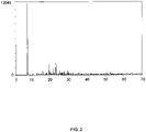
- a layered silicate of the type AI-RUB-39 was obtained, the X-ray diffractogram of which is shown in Figure 6 will be shown.
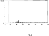
- the AI-RUB-39 type layered silicate produced using NaOH was calcined at 600° C. for 3 h, giving a framework silicate of the AI-RUB-41 structure type.
- the X-ray diffractogram of the framework silicate obtained in this way is Figure 7 shown.
- Example 8 Separation of olefins in the liquid phase using a heteroatom-free framework silicate of the structure RUB-41 ("allsilica RUB-41")
- RUB-41 according to example 5 as well as silicalite and ferrierite were added in about 1.1 ml cyclohexane solution containing trans-2-butene and 1-butene in a chromatographic vial. This solution contained approximately 0.5% by weight of each butene. To avoid escaping the butenes, the vial was filled completely. After overnight equilibration, the supernatant was injected into the GC. The analysis was compared to analysis of an identical solution in an identical vial containing no RUB-41 or silicalite or ferrierite.
- alpha m t ⁇ 2 ⁇ butene , zeolite / m 1 ⁇ butene , zeolite / m t ⁇ 2 ⁇ butene , liquid phase / m 1 ⁇ butene , liquid phase
Landscapes
- Chemical & Material Sciences (AREA)
- Organic Chemistry (AREA)
- Life Sciences & Earth Sciences (AREA)
- General Life Sciences & Earth Sciences (AREA)
- Geology (AREA)
- Inorganic Chemistry (AREA)
- Silicates, Zeolites, And Molecular Sieves (AREA)
Applications Claiming Priority (4)
| Application Number | Priority Date | Filing Date | Title |
|---|---|---|---|
| DE102005049362A DE102005049362A1 (de) | 2005-10-12 | 2005-10-12 | Verfahren zur Herstellung eines Silikates |
| EP13158384.1A EP2634145A3 (de) | 2005-10-12 | 2006-10-11 | Verfahren zur Herstellung eines Silikates |
| PCT/EP2006/067269 WO2007042531A2 (de) | 2005-10-12 | 2006-10-11 | Verfahren zur herstellung eines silikates |
| EP06794010.6A EP1937594B1 (de) | 2005-10-12 | 2006-10-11 | Verfahren zur herstellung eines silikates |
Related Parent Applications (2)
| Application Number | Title | Priority Date | Filing Date |
|---|---|---|---|
| EP06794010.6A Division EP1937594B1 (de) | 2005-10-12 | 2006-10-11 | Verfahren zur herstellung eines silikates |
| EP13158384.1A Division EP2634145A3 (de) | 2005-10-12 | 2006-10-11 | Verfahren zur Herstellung eines Silikates |
Publications (2)
| Publication Number | Publication Date |
|---|---|
| EP3536666A1 EP3536666A1 (de) | 2019-09-11 |
| EP3536666B1 true EP3536666B1 (de) | 2022-12-07 |
Family
ID=37896410
Family Applications (3)
| Application Number | Title | Priority Date | Filing Date |
|---|---|---|---|
| EP19164236.2A Active EP3536666B1 (de) | 2005-10-12 | 2006-10-11 | Schichtsilikat und gerüstsilikat |
| EP13158384.1A Ceased EP2634145A3 (de) | 2005-10-12 | 2006-10-11 | Verfahren zur Herstellung eines Silikates |
| EP06794010.6A Active EP1937594B1 (de) | 2005-10-12 | 2006-10-11 | Verfahren zur herstellung eines silikates |
Family Applications After (2)
| Application Number | Title | Priority Date | Filing Date |
|---|---|---|---|
| EP13158384.1A Ceased EP2634145A3 (de) | 2005-10-12 | 2006-10-11 | Verfahren zur Herstellung eines Silikates |
| EP06794010.6A Active EP1937594B1 (de) | 2005-10-12 | 2006-10-11 | Verfahren zur herstellung eines silikates |
Country Status (6)
| Country | Link |
|---|---|
| US (2) | US7947244B2 (https=) |
| EP (3) | EP3536666B1 (https=) |
| JP (2) | JP5383195B2 (https=) |
| CN (2) | CN101326121B (https=) |
| DE (1) | DE102005049362A1 (https=) |
| WO (1) | WO2007042531A2 (https=) |
Families Citing this family (15)
| Publication number | Priority date | Publication date | Assignee | Title |
|---|---|---|---|---|
| EP2160355B1 (de) * | 2007-04-04 | 2011-08-31 | Basf Se | Verfahren zur herstellung eines heteroatom enthaltenden silikates |
| CN102341350B (zh) * | 2009-03-03 | 2015-12-02 | 巴斯夫欧洲公司 | 同晶取代硅酸盐 |
| WO2010099651A1 (en) * | 2009-03-03 | 2010-09-10 | Basf Se | Process for preparation of isomorphously substituted layered silicate, silicate prepared by process, and uses thereof |
| WO2010099650A1 (en) * | 2009-03-03 | 2010-09-10 | Basf Se | Isomorphously substituted silicate |
| WO2010099649A1 (en) * | 2009-03-03 | 2010-09-10 | Basf Se | Process for preparation of pillared silicates |
| CN102355949B (zh) * | 2009-03-03 | 2014-07-16 | 巴斯夫欧洲公司 | 制备同晶取代硅酸盐的方法 |
| US8426332B2 (en) | 2010-07-02 | 2013-04-23 | Basf Se | Metal-bridged pillared silicate compounds and process for their production |
| US9028795B2 (en) * | 2011-09-09 | 2015-05-12 | Basf Se | Process for the organotemplate-free synthetic production of a zeolitic material using recycled mother liquor |
| JP6484894B2 (ja) * | 2014-03-28 | 2019-03-20 | 山口精研工業株式会社 | 研磨剤組成物、および磁気ディスク基板の研磨方法 |
| MY177370A (en) * | 2014-03-28 | 2020-09-14 | Yamaguchi Seiken Kogyo Co Ltd | Polishing composition and method for polishing magnetic disk substrate |
| JP2020055717A (ja) * | 2018-10-03 | 2020-04-09 | 石原産業株式会社 | アルミニウムケイ酸塩の製造方法 |
| CN113479897B (zh) * | 2021-07-16 | 2023-10-24 | 常州大学 | 利用凹凸棒石制备二维纳米片硅酸盐的方法及其应用 |
| KR102656777B1 (ko) | 2022-03-29 | 2024-04-11 | 닛산 가가쿠 가부시키가이샤 | 층상 규산염의 제조 방법, 및 실리카 나노 시트의 제조 등에 있어서의 그 응용 |
| EP4279454A4 (en) * | 2022-03-29 | 2024-04-03 | Nissan Chemical Corporation | Cage silicate and method for producing same |
| WO2025129604A1 (en) * | 2023-12-22 | 2025-06-26 | Rhodia Operations | A method for recovering a silicate from polymeric composition comprising silica |
Family Cites Families (30)
| Publication number | Priority date | Publication date | Assignee | Title |
|---|---|---|---|---|
| DE3274844D1 (en) * | 1981-04-14 | 1987-02-05 | Ici Plc | Zeolites |
| AU568400B2 (en) * | 1983-08-31 | 1987-12-24 | E.I. Du Pont De Nemours And Company | Preparation of silica polymorphs from silicon |
| ZA846795B (en) * | 1983-08-31 | 1986-04-30 | Du Pont | Process for the preparation of silica polymorphs from silicon |
| US4495303A (en) * | 1983-11-29 | 1985-01-22 | Mobil Oil Corporation | Process for making zeolite ZSM-45 with a dimethyldiethylammonium directing agent |
| AU571028B2 (en) * | 1983-12-09 | 1988-03-31 | Mobil Oil Corp. | Crystalline zeolite zsm 12 |
| DE3402842A1 (de) * | 1984-01-27 | 1985-08-08 | Süd-Chemie AG, 8000 München | Verfahren zur herstellung von kristallinen zeolithischen alumosilicaten |
| DE3669490D1 (de) * | 1985-06-13 | 1990-04-19 | Hoechst Ag | Verfahren zur herstellung von kristallinen alkalischichtsilikaten. |
| JPH07113484B2 (ja) | 1987-08-27 | 1995-12-06 | 松下電器産業株式会社 | 電気湯沸し器などの発熱体 |
| GB9122498D0 (en) * | 1991-10-23 | 1991-12-04 | Exxon Chemical Patents Inc | Process for preparing uniform mfitype zeolite crystals |
| US5139759A (en) * | 1991-12-19 | 1992-08-18 | Uop | Synthesis of zeolite beta |
| DE4200787A1 (de) * | 1992-01-15 | 1993-07-22 | Bayer Ag | Verfahren zur herstellung von si(pfeil abwaerts)3(pfeil abwaerts)(pfeil hoch)n(pfeil hoch)(pfeil abwaerts)4(pfeil abwaerts), neue ausgangsverbindung hierfuer sowie verfahren zu dessen herstellung |
| DE4308063A1 (de) * | 1993-03-13 | 1994-09-15 | Hoechst Ag | Verfahren zur Herstellung von Gemischen aus synthetischem, kristallinem Magadiit und sauerstoffabspaltenden Salzen sowie deren Verwendung |
| DE4308062A1 (de) * | 1993-03-13 | 1994-09-15 | Hoechst Ag | Verfahren zur Herstellung von Gemischen aus synthetischem, kristallinem Kenyait und sauerstoffabspaltenden Salzen sowie deren Verwendung |
| FR2727397B1 (fr) * | 1994-11-30 | 1997-01-24 | Inst Francais Du Petrole | Procede de synthese de zeolithes et de solides mesoporeux a partir d'une solution homogene en systeme semi-ouvert |
| US5885546A (en) * | 1994-12-09 | 1999-03-23 | Council Of Scientific & Industrial Research | Process for the preparation of titanium silicates |
| EP0731058B1 (de) * | 1995-03-06 | 2000-07-26 | Clariant GmbH | Kristallines Natriumschichtsilikat |
| GB9600082D0 (en) * | 1996-01-04 | 1996-03-06 | Exxon Chemical Patents Inc | Molecular sieves and processes for their manufacture |
| IT1284007B1 (it) * | 1996-06-13 | 1998-05-08 | Eniricerche Spa | Procedimento per la preparazione di un materiale micro-meso poroso ad alta area superficiale con distribuzione controllata della |
| JPH10310417A (ja) * | 1997-04-30 | 1998-11-24 | Lion Corp | 含水層状珪酸塩、その製造方法、水軟化剤および洗浄剤組成物 |
| DE19723949A1 (de) | 1997-06-06 | 1998-12-10 | Basf Ag | Verfahren zur Regenerierung eines Zeolith-Katalysators |
| DE10001831A1 (de) * | 2000-01-18 | 2001-08-16 | Keimfarben Gmbh & Co Kg | Silikatische Beschichtungsmasse mit verbesserter Stabilität |
| US6329062B1 (en) * | 2000-02-29 | 2001-12-11 | Novellus Systems, Inc. | Dielectric layer including silicalite crystals and binder and method for producing same for microelectronic circuits |
| JP4459369B2 (ja) * | 2000-03-02 | 2010-04-28 | 日本碍子株式会社 | 多孔質基体、ゼオライト複合膜及びその製造方法 |
| WO2001064583A1 (en) * | 2000-03-02 | 2001-09-07 | Ngk Insulators, Ltd. | Zeolite formed product, zeolite laminate intermediate, zeolite laminate composite and method for their preparation |
| CN1173395C (zh) * | 2001-01-05 | 2004-10-27 | 联华电子股份有限公司 | 以覆盖层制造铜内连线的方法 |
| WO2002062703A2 (en) * | 2001-02-02 | 2002-08-15 | The University Of Houston System | Microporous crystalline metal silicates and processes for their preparation |
| FR2840296B1 (fr) * | 2002-06-03 | 2004-08-20 | Inst Francais Du Petrole | Procede de preparation d'une membrane zeolithique de faible epaisseur |
| EP1688393B1 (en) * | 2003-11-17 | 2012-01-11 | National Institute of Advanced Industrial Science and Technology | High silica cds-1 zeolite |
| JP4348431B2 (ja) * | 2003-11-17 | 2009-10-21 | 独立行政法人産業技術総合研究所 | 高シリカ型cds−1ゼオライト膜及びその製造方法 |
| DE102004017915A1 (de) * | 2004-04-13 | 2005-11-03 | Basf Ag | Mikroporöses Gerüstsilikat und Verfahren zu seiner Herstellung |
-
2005
- 2005-10-12 DE DE102005049362A patent/DE102005049362A1/de not_active Withdrawn
-
2006
- 2006-10-11 JP JP2008535020A patent/JP5383195B2/ja not_active Expired - Fee Related
- 2006-10-11 EP EP19164236.2A patent/EP3536666B1/de active Active
- 2006-10-11 US US12/090,027 patent/US7947244B2/en active Active
- 2006-10-11 EP EP13158384.1A patent/EP2634145A3/de not_active Ceased
- 2006-10-11 WO PCT/EP2006/067269 patent/WO2007042531A2/de not_active Ceased
- 2006-10-11 EP EP06794010.6A patent/EP1937594B1/de active Active
- 2006-10-11 CN CN2006800459389A patent/CN101326121B/zh not_active Expired - Fee Related
- 2006-10-11 CN CN201210192525.0A patent/CN102745699B/zh not_active Expired - Fee Related
-
2011
- 2011-04-08 US US13/082,603 patent/US8372378B2/en not_active Expired - Fee Related
-
2013
- 2013-06-17 JP JP2013126885A patent/JP2013177312A/ja active Pending
Also Published As
| Publication number | Publication date |
|---|---|
| EP2634145A3 (de) | 2014-08-13 |
| US20110182793A1 (en) | 2011-07-28 |
| WO2007042531A2 (de) | 2007-04-19 |
| EP2634145A2 (de) | 2013-09-04 |
| JP5383195B2 (ja) | 2014-01-08 |
| CN101326121A (zh) | 2008-12-17 |
| US20080253953A1 (en) | 2008-10-16 |
| EP1937594A2 (de) | 2008-07-02 |
| CN102745699A (zh) | 2012-10-24 |
| EP3536666A1 (de) | 2019-09-11 |
| US8372378B2 (en) | 2013-02-12 |
| JP2009511409A (ja) | 2009-03-19 |
| WO2007042531A3 (de) | 2007-09-13 |
| JP2013177312A (ja) | 2013-09-09 |
| CN102745699B (zh) | 2016-01-06 |
| US7947244B2 (en) | 2011-05-24 |
| EP1937594B1 (de) | 2014-01-29 |
| DE102005049362A1 (de) | 2007-04-19 |
| CN101326121B (zh) | 2012-07-18 |
Similar Documents
| Publication | Publication Date | Title |
|---|---|---|
| EP2160355B1 (de) | Verfahren zur herstellung eines heteroatom enthaltenden silikates | |
| EP1737791B1 (de) | Mikroporöses gerüstsilikat und verfahren zu seiner herstellung | |
| EP3536666B1 (de) | Schichtsilikat und gerüstsilikat | |
| EP2490985B1 (en) | Method of preparing zsm-5 zeolite using nanocrystalline zsm-5 seeds | |
| DE60206914T2 (de) | Synthetisches poröses kristallines material itq-3 und synthese sowie verwendung davon | |
| DE60006771T2 (de) | Verfahren zur Herstellung eines Zeoliths des EUO-Typs unter Verwendung von zeolithischen Keimen | |
| EP1697043A1 (de) | Zeolithisches material vom pentasil-strukturtyp,seine herstellung und seine verwendung | |
| EP1809576B1 (de) | Verfahren zur synthese von zeolith beta mit diethylentriamin | |
| DE102010053054A1 (de) | Mechanochemische Herstellung von Zeolithen | |
| WO2009124902A1 (de) | Katalysator zur dehydroaromatisierung von aliphatischen kohlenwasserstoffen mit siliziumhaltigem bindemittel | |
| WO2004087315A1 (de) | Synthetischer zeolith, insbesondere für die katalytische hydroisomerisierung von höheren paraffinen | |
| EP2528684B1 (de) | Verbesserter katalysator auf zeolithbasis zur herstellung von olefinen und zur oligomerisierung von olefinen | |
| DE4424815A1 (de) | Kristalline Festkörper mit RUB-13 Struktur | |
| DE60123848T2 (de) | Synthetisches poröses kristallines material mcm-71, dessen synthese und verwendung | |
| DE69614701T2 (de) | Synthetisches, poröses, kristallines mcm 61, dessen synthese und verwendung | |
| DE3886952T2 (de) | Synthetisches, poröses, kristallines material sowie dessen synthese und verwendung. |
Legal Events
| Date | Code | Title | Description |
|---|---|---|---|
| PUAI | Public reference made under article 153(3) epc to a published international application that has entered the european phase |
Free format text: ORIGINAL CODE: 0009012 |
|
| STAA | Information on the status of an ep patent application or granted ep patent |
Free format text: STATUS: THE APPLICATION HAS BEEN PUBLISHED |
|
| AC | Divisional application: reference to earlier application |
Ref document number: 1937594 Country of ref document: EP Kind code of ref document: P Ref document number: 2634145 Country of ref document: EP Kind code of ref document: P |
|
| AK | Designated contracting states |
Kind code of ref document: A1 Designated state(s): AT BE BG CH CY CZ DE DK EE ES FI FR GB GR HU IE IS IT LI LT LU LV MC NL PL PT RO SE SI SK TR |
|
| STAA | Information on the status of an ep patent application or granted ep patent |
Free format text: STATUS: REQUEST FOR EXAMINATION WAS MADE |
|
| 17P | Request for examination filed |
Effective date: 20200311 |
|
| RBV | Designated contracting states (corrected) |
Designated state(s): AT BE BG CH CY CZ DE DK EE ES FI FR GB GR HU IE IS IT LI LT LU LV MC NL PL PT RO SE SI SK TR |
|
| STAA | Information on the status of an ep patent application or granted ep patent |
Free format text: STATUS: EXAMINATION IS IN PROGRESS |
|
| 17Q | First examination report despatched |
Effective date: 20210511 |
|
| GRAP | Despatch of communication of intention to grant a patent |
Free format text: ORIGINAL CODE: EPIDOSNIGR1 |
|
| STAA | Information on the status of an ep patent application or granted ep patent |
Free format text: STATUS: GRANT OF PATENT IS INTENDED |
|
| INTG | Intention to grant announced |
Effective date: 20220624 |
|
| GRAS | Grant fee paid |
Free format text: ORIGINAL CODE: EPIDOSNIGR3 |
|
| GRAA | (expected) grant |
Free format text: ORIGINAL CODE: 0009210 |
|
| STAA | Information on the status of an ep patent application or granted ep patent |
Free format text: STATUS: THE PATENT HAS BEEN GRANTED |
|
| AC | Divisional application: reference to earlier application |
Ref document number: 1937594 Country of ref document: EP Kind code of ref document: P Ref document number: 2634145 Country of ref document: EP Kind code of ref document: P |
|
| AK | Designated contracting states |
Kind code of ref document: B1 Designated state(s): AT BE BG CH CY CZ DE DK EE ES FI FR GB GR HU IE IS IT LI LT LU LV MC NL PL PT RO SE SI SK TR |
|
| REG | Reference to a national code |
Ref country code: GB Ref legal event code: FG4D Free format text: NOT ENGLISH |
|
| REG | Reference to a national code |
Ref country code: CH Ref legal event code: EP Ref country code: AT Ref legal event code: REF Ref document number: 1536226 Country of ref document: AT Kind code of ref document: T Effective date: 20221215 |
|
| REG | Reference to a national code |
Ref country code: DE Ref legal event code: R096 Ref document number: 502006016488 Country of ref document: DE |
|
| REG | Reference to a national code |
Ref country code: IE Ref legal event code: FG4D Free format text: LANGUAGE OF EP DOCUMENT: GERMAN |
|
| REG | Reference to a national code |
Ref country code: NL Ref legal event code: FP |
|
| REG | Reference to a national code |
Ref country code: LT Ref legal event code: MG9D |
|
| PG25 | Lapsed in a contracting state [announced via postgrant information from national office to epo] |
Ref country code: SE Free format text: LAPSE BECAUSE OF FAILURE TO SUBMIT A TRANSLATION OF THE DESCRIPTION OR TO PAY THE FEE WITHIN THE PRESCRIBED TIME-LIMIT Effective date: 20221207 Ref country code: LT Free format text: LAPSE BECAUSE OF FAILURE TO SUBMIT A TRANSLATION OF THE DESCRIPTION OR TO PAY THE FEE WITHIN THE PRESCRIBED TIME-LIMIT Effective date: 20221207 Ref country code: FI Free format text: LAPSE BECAUSE OF FAILURE TO SUBMIT A TRANSLATION OF THE DESCRIPTION OR TO PAY THE FEE WITHIN THE PRESCRIBED TIME-LIMIT Effective date: 20221207 Ref country code: ES Free format text: LAPSE BECAUSE OF FAILURE TO SUBMIT A TRANSLATION OF THE DESCRIPTION OR TO PAY THE FEE WITHIN THE PRESCRIBED TIME-LIMIT Effective date: 20221207 |
|
| PG25 | Lapsed in a contracting state [announced via postgrant information from national office to epo] |
Ref country code: PL Free format text: LAPSE BECAUSE OF FAILURE TO SUBMIT A TRANSLATION OF THE DESCRIPTION OR TO PAY THE FEE WITHIN THE PRESCRIBED TIME-LIMIT Effective date: 20221207 Ref country code: LV Free format text: LAPSE BECAUSE OF FAILURE TO SUBMIT A TRANSLATION OF THE DESCRIPTION OR TO PAY THE FEE WITHIN THE PRESCRIBED TIME-LIMIT Effective date: 20221207 Ref country code: GR Free format text: LAPSE BECAUSE OF FAILURE TO SUBMIT A TRANSLATION OF THE DESCRIPTION OR TO PAY THE FEE WITHIN THE PRESCRIBED TIME-LIMIT Effective date: 20230308 |
|
| PG25 | Lapsed in a contracting state [announced via postgrant information from national office to epo] |
Ref country code: RO Free format text: LAPSE BECAUSE OF FAILURE TO SUBMIT A TRANSLATION OF THE DESCRIPTION OR TO PAY THE FEE WITHIN THE PRESCRIBED TIME-LIMIT Effective date: 20221207 Ref country code: PT Free format text: LAPSE BECAUSE OF FAILURE TO SUBMIT A TRANSLATION OF THE DESCRIPTION OR TO PAY THE FEE WITHIN THE PRESCRIBED TIME-LIMIT Effective date: 20230410 Ref country code: EE Free format text: LAPSE BECAUSE OF FAILURE TO SUBMIT A TRANSLATION OF THE DESCRIPTION OR TO PAY THE FEE WITHIN THE PRESCRIBED TIME-LIMIT Effective date: 20221207 Ref country code: CZ Free format text: LAPSE BECAUSE OF FAILURE TO SUBMIT A TRANSLATION OF THE DESCRIPTION OR TO PAY THE FEE WITHIN THE PRESCRIBED TIME-LIMIT Effective date: 20221207 |
|
| PG25 | Lapsed in a contracting state [announced via postgrant information from national office to epo] |
Ref country code: SK Free format text: LAPSE BECAUSE OF FAILURE TO SUBMIT A TRANSLATION OF THE DESCRIPTION OR TO PAY THE FEE WITHIN THE PRESCRIBED TIME-LIMIT Effective date: 20221207 Ref country code: IS Free format text: LAPSE BECAUSE OF FAILURE TO SUBMIT A TRANSLATION OF THE DESCRIPTION OR TO PAY THE FEE WITHIN THE PRESCRIBED TIME-LIMIT Effective date: 20230407 |
|
| REG | Reference to a national code |
Ref country code: DE Ref legal event code: R097 Ref document number: 502006016488 Country of ref document: DE |
|
| PLBE | No opposition filed within time limit |
Free format text: ORIGINAL CODE: 0009261 |
|
| STAA | Information on the status of an ep patent application or granted ep patent |
Free format text: STATUS: NO OPPOSITION FILED WITHIN TIME LIMIT |
|
| PG25 | Lapsed in a contracting state [announced via postgrant information from national office to epo] |
Ref country code: DK Free format text: LAPSE BECAUSE OF FAILURE TO SUBMIT A TRANSLATION OF THE DESCRIPTION OR TO PAY THE FEE WITHIN THE PRESCRIBED TIME-LIMIT Effective date: 20221207 |
|
| 26N | No opposition filed |
Effective date: 20230908 |
|
| PG25 | Lapsed in a contracting state [announced via postgrant information from national office to epo] |
Ref country code: SI Free format text: LAPSE BECAUSE OF FAILURE TO SUBMIT A TRANSLATION OF THE DESCRIPTION OR TO PAY THE FEE WITHIN THE PRESCRIBED TIME-LIMIT Effective date: 20221207 |
|
| REG | Reference to a national code |
Ref country code: DE Ref legal event code: R119 Ref document number: 502006016488 Country of ref document: DE |
|
| PG25 | Lapsed in a contracting state [announced via postgrant information from national office to epo] |
Ref country code: MC Free format text: LAPSE BECAUSE OF FAILURE TO SUBMIT A TRANSLATION OF THE DESCRIPTION OR TO PAY THE FEE WITHIN THE PRESCRIBED TIME-LIMIT Effective date: 20221207 |
|
| REG | Reference to a national code |
Ref country code: CH Ref legal event code: PL |
|
| REG | Reference to a national code |
Ref country code: NL Ref legal event code: MM Effective date: 20231101 |
|
| REG | Reference to a national code |
Ref country code: BE Ref legal event code: MM Effective date: 20231031 |
|
| PG25 | Lapsed in a contracting state [announced via postgrant information from national office to epo] |
Ref country code: LU Free format text: LAPSE BECAUSE OF NON-PAYMENT OF DUE FEES Effective date: 20231011 |
|
| GBPC | Gb: european patent ceased through non-payment of renewal fee |
Effective date: 20231011 |
|
| PG25 | Lapsed in a contracting state [announced via postgrant information from national office to epo] |
Ref country code: LU Free format text: LAPSE BECAUSE OF NON-PAYMENT OF DUE FEES Effective date: 20231011 |
|
| PG25 | Lapsed in a contracting state [announced via postgrant information from national office to epo] |
Ref country code: GB Free format text: LAPSE BECAUSE OF NON-PAYMENT OF DUE FEES Effective date: 20231011 |
|
| PG25 | Lapsed in a contracting state [announced via postgrant information from national office to epo] |
Ref country code: CH Free format text: LAPSE BECAUSE OF NON-PAYMENT OF DUE FEES Effective date: 20231031 Ref country code: NL Free format text: LAPSE BECAUSE OF NON-PAYMENT OF DUE FEES Effective date: 20231101 |
|
| PG25 | Lapsed in a contracting state [announced via postgrant information from national office to epo] |
Ref country code: NL Free format text: LAPSE BECAUSE OF NON-PAYMENT OF DUE FEES Effective date: 20231101 Ref country code: GB Free format text: LAPSE BECAUSE OF NON-PAYMENT OF DUE FEES Effective date: 20231011 Ref country code: FR Free format text: LAPSE BECAUSE OF NON-PAYMENT OF DUE FEES Effective date: 20231031 Ref country code: DE Free format text: LAPSE BECAUSE OF NON-PAYMENT OF DUE FEES Effective date: 20240501 Ref country code: CH Free format text: LAPSE BECAUSE OF NON-PAYMENT OF DUE FEES Effective date: 20231031 |
|
| PG25 | Lapsed in a contracting state [announced via postgrant information from national office to epo] |
Ref country code: BE Free format text: LAPSE BECAUSE OF NON-PAYMENT OF DUE FEES Effective date: 20231031 |
|
| PG25 | Lapsed in a contracting state [announced via postgrant information from national office to epo] |
Ref country code: IE Free format text: LAPSE BECAUSE OF NON-PAYMENT OF DUE FEES Effective date: 20231011 |
|
| PG25 | Lapsed in a contracting state [announced via postgrant information from national office to epo] |
Ref country code: IE Free format text: LAPSE BECAUSE OF NON-PAYMENT OF DUE FEES Effective date: 20231011 |
|
| PG25 | Lapsed in a contracting state [announced via postgrant information from national office to epo] |
Ref country code: BG Free format text: LAPSE BECAUSE OF FAILURE TO SUBMIT A TRANSLATION OF THE DESCRIPTION OR TO PAY THE FEE WITHIN THE PRESCRIBED TIME-LIMIT Effective date: 20221207 |
|
| PG25 | Lapsed in a contracting state [announced via postgrant information from national office to epo] |
Ref country code: BG Free format text: LAPSE BECAUSE OF FAILURE TO SUBMIT A TRANSLATION OF THE DESCRIPTION OR TO PAY THE FEE WITHIN THE PRESCRIBED TIME-LIMIT Effective date: 20221207 |
|
| PG25 | Lapsed in a contracting state [announced via postgrant information from national office to epo] |
Ref country code: IT Free format text: LAPSE BECAUSE OF NON-PAYMENT OF DUE FEES Effective date: 20231011 |
|
| REG | Reference to a national code |
Ref country code: AT Ref legal event code: MM01 Ref document number: 1536226 Country of ref document: AT Kind code of ref document: T Effective date: 20231011 |
|
| PG25 | Lapsed in a contracting state [announced via postgrant information from national office to epo] |
Ref country code: IT Free format text: LAPSE BECAUSE OF NON-PAYMENT OF DUE FEES Effective date: 20231011 |
|
| PG25 | Lapsed in a contracting state [announced via postgrant information from national office to epo] |
Ref country code: AT Free format text: LAPSE BECAUSE OF NON-PAYMENT OF DUE FEES Effective date: 20231011 |
|
| PG25 | Lapsed in a contracting state [announced via postgrant information from national office to epo] |
Ref country code: AT Free format text: LAPSE BECAUSE OF NON-PAYMENT OF DUE FEES Effective date: 20231011 |
|
| PG25 | Lapsed in a contracting state [announced via postgrant information from national office to epo] |
Ref country code: CY Free format text: LAPSE BECAUSE OF FAILURE TO SUBMIT A TRANSLATION OF THE DESCRIPTION OR TO PAY THE FEE WITHIN THE PRESCRIBED TIME-LIMIT; INVALID AB INITIO Effective date: 20061011 |
|
| PG25 | Lapsed in a contracting state [announced via postgrant information from national office to epo] |
Ref country code: HU Free format text: LAPSE BECAUSE OF FAILURE TO SUBMIT A TRANSLATION OF THE DESCRIPTION OR TO PAY THE FEE WITHIN THE PRESCRIBED TIME-LIMIT; INVALID AB INITIO Effective date: 20061011 |
|
| PG25 | Lapsed in a contracting state [announced via postgrant information from national office to epo] |
Ref country code: TR Free format text: LAPSE BECAUSE OF FAILURE TO SUBMIT A TRANSLATION OF THE DESCRIPTION OR TO PAY THE FEE WITHIN THE PRESCRIBED TIME-LIMIT Effective date: 20221207 |