EP3536653B1 - Flurförderzeug mit einem hydraulikflüssigkeitstank - Google Patents
Flurförderzeug mit einem hydraulikflüssigkeitstank Download PDFInfo
- Publication number
- EP3536653B1 EP3536653B1 EP19159787.1A EP19159787A EP3536653B1 EP 3536653 B1 EP3536653 B1 EP 3536653B1 EP 19159787 A EP19159787 A EP 19159787A EP 3536653 B1 EP3536653 B1 EP 3536653B1
- Authority
- EP
- European Patent Office
- Prior art keywords
- hydraulic fluid
- fluid tank
- feet
- industrial truck
- truck according
- Prior art date
- Legal status (The legal status is an assumption and is not a legal conclusion. Google has not performed a legal analysis and makes no representation as to the accuracy of the status listed.)
- Active
Links
Images



Classifications
-
- B—PERFORMING OPERATIONS; TRANSPORTING
- B66—HOISTING; LIFTING; HAULING
- B66F—HOISTING, LIFTING, HAULING OR PUSHING, NOT OTHERWISE PROVIDED FOR, e.g. DEVICES WHICH APPLY A LIFTING OR PUSHING FORCE DIRECTLY TO THE SURFACE OF A LOAD
- B66F9/00—Devices for lifting or lowering bulky or heavy goods for loading or unloading purposes
- B66F9/06—Devices for lifting or lowering bulky or heavy goods for loading or unloading purposes movable, with their loads, on wheels or the like, e.g. fork-lift trucks
- B66F9/075—Constructional features or details
-
- B—PERFORMING OPERATIONS; TRANSPORTING
- B66—HOISTING; LIFTING; HAULING
- B66F—HOISTING, LIFTING, HAULING OR PUSHING, NOT OTHERWISE PROVIDED FOR, e.g. DEVICES WHICH APPLY A LIFTING OR PUSHING FORCE DIRECTLY TO THE SURFACE OF A LOAD
- B66F9/00—Devices for lifting or lowering bulky or heavy goods for loading or unloading purposes
- B66F9/06—Devices for lifting or lowering bulky or heavy goods for loading or unloading purposes movable, with their loads, on wheels or the like, e.g. fork-lift trucks
- B66F9/075—Constructional features or details
- B66F9/07504—Accessories, e.g. for towing, charging, locking
-
- B—PERFORMING OPERATIONS; TRANSPORTING
- B66—HOISTING; LIFTING; HAULING
- B66F—HOISTING, LIFTING, HAULING OR PUSHING, NOT OTHERWISE PROVIDED FOR, e.g. DEVICES WHICH APPLY A LIFTING OR PUSHING FORCE DIRECTLY TO THE SURFACE OF A LOAD
- B66F9/00—Devices for lifting or lowering bulky or heavy goods for loading or unloading purposes
- B66F9/06—Devices for lifting or lowering bulky or heavy goods for loading or unloading purposes movable, with their loads, on wheels or the like, e.g. fork-lift trucks
- B66F9/075—Constructional features or details
- B66F9/07513—Details concerning the chassis
-
- B—PERFORMING OPERATIONS; TRANSPORTING
- B66—HOISTING; LIFTING; HAULING
- B66F—HOISTING, LIFTING, HAULING OR PUSHING, NOT OTHERWISE PROVIDED FOR, e.g. DEVICES WHICH APPLY A LIFTING OR PUSHING FORCE DIRECTLY TO THE SURFACE OF A LOAD
- B66F9/00—Devices for lifting or lowering bulky or heavy goods for loading or unloading purposes
- B66F9/06—Devices for lifting or lowering bulky or heavy goods for loading or unloading purposes movable, with their loads, on wheels or the like, e.g. fork-lift trucks
- B66F9/075—Constructional features or details
- B66F9/07513—Details concerning the chassis
- B66F9/07518—Fuel or oil tank arrangements
-
- B—PERFORMING OPERATIONS; TRANSPORTING
- B66—HOISTING; LIFTING; HAULING
- B66F—HOISTING, LIFTING, HAULING OR PUSHING, NOT OTHERWISE PROVIDED FOR, e.g. DEVICES WHICH APPLY A LIFTING OR PUSHING FORCE DIRECTLY TO THE SURFACE OF A LOAD
- B66F9/00—Devices for lifting or lowering bulky or heavy goods for loading or unloading purposes
- B66F9/06—Devices for lifting or lowering bulky or heavy goods for loading or unloading purposes movable, with their loads, on wheels or the like, e.g. fork-lift trucks
- B66F9/075—Constructional features or details
- B66F9/20—Means for actuating or controlling masts, platforms, or forks
- B66F9/22—Hydraulic devices or systems
-
- B—PERFORMING OPERATIONS; TRANSPORTING
- B60—VEHICLES IN GENERAL
- B60Y—INDEXING SCHEME RELATING TO ASPECTS CROSS-CUTTING VEHICLE TECHNOLOGY
- B60Y2200/00—Type of vehicle
- B60Y2200/40—Special vehicles
-
- Y—GENERAL TAGGING OF NEW TECHNOLOGICAL DEVELOPMENTS; GENERAL TAGGING OF CROSS-SECTIONAL TECHNOLOGIES SPANNING OVER SEVERAL SECTIONS OF THE IPC; TECHNICAL SUBJECTS COVERED BY FORMER USPC CROSS-REFERENCE ART COLLECTIONS [XRACs] AND DIGESTS
- Y10—TECHNICAL SUBJECTS COVERED BY FORMER USPC
- Y10T—TECHNICAL SUBJECTS COVERED BY FORMER US CLASSIFICATION
- Y10T137/00—Fluid handling
- Y10T137/6851—With casing, support, protector or static constructional installations
- Y10T137/6855—Vehicle
Definitions
- the invention relates to an industrial truck with a hydraulic fluid tank.
- Such tanks hold hydraulic fluid for operating the hydraulic components of the industrial truck, in particular a hydraulically driven lifting device.
- the hydraulic fluid tank must offer a high level of security against unwanted leakage of the hydraulic fluid and, in view of the accelerations and vibrations that occur during operation of the vehicle, must be securely attached to the industrial truck and protected from external influences.
- the hydraulic fluid tank has a considerable volume that holds the hydraulic fluid and is usually surrounded by a relatively thin wall. Hydraulic lines connected to the hydraulic fluid tank are sealed against the wall.
- the hydraulic fluid tank is attached to a support of the industrial truck using a clamp or similar bracket.
- the clamp or other bracket encloses part of the hydraulic fluid tank and clamps the hydraulic fluid tank to the support. This fixes the hydraulic fluid tank relative to the support so that it cannot slip when the industrial truck is in operation.
- the hydraulic fluid tank is at least partially surrounded by a receiving space provided for this purpose in the industrial truck, with spacers, for example in the form of foam rubber plates, being arranged between the inner sides of the receiving space facing the hydraulic fluid tank and the hydraulic fluid tank. In this way, the hydraulic fluid tank is secured against slipping in the receiving space.
- a hydraulic tank of an industrial truck according to the preamble of claim 1 is known, which has support formations on both its underside and its upper side for storing and fastening the tank in an industrial truck.
- JP H 11 322 292 A describes an industrial truck with a carrier that has exactly one mount for holding a projection of a hydraulic tank. Spacers are also provided above and to the side of the tank to secure the hydraulic tank.
- the object of the invention is to provide an industrial truck in which the hydraulic fluid tank is attached in a particularly simple and yet safe manner.
- the industrial truck has a carrier and a hydraulic fluid tank, whereby the hydraulic fluid tank has several feet and the carrier has several receptacles into which one of the feet is inserted.
- the feet can be arranged on the underside of the hydraulic fluid tank. They can protrude downwards from a bottom surface of the hydraulic fluid tank. There can be at least three feet, but also four or more feet. Each foot can be assigned a correspondingly arranged holder of the carrier.
- the holders each have a free space, for example in the form of a recess or a hole, which accommodates one of the feet or part of it.
- the hydraulic fluid tank To install the hydraulic fluid tank, it is sufficient to arrange the hydraulic fluid tank with its feet in a designated space on the industrial truck and insert the feet into the holders. If the hydraulic fluid tank is to be removed again, for example as part of Maintenance work, it can be easily removed upwards by pulling the feet out of the holders. It has been found that the interaction of the feet with the holders alone provides sufficient fastening of the hydraulic fluid tank. The positive connection between each of the feet and the associated holder reliably prevents the hydraulic fluid tank from slipping in lateral direction. Additional fixation of the hydraulic fluid tank in the vertical direction has proven to be unnecessary. Even with strong acceleration or impacts, such as those that can occur when driving over a threshold, the hydraulic fluid tank remains in its installed position.
- the interaction of the feet with the mounts enables particularly precise positioning of the hydraulic fluid tank in the intended installation position.
- This helps to ensure that elements formed on the hydraulic fluid tank or connected to it, for example a filler neck for filling the hydraulic fluid tank, are also positioned precisely relative to the carrier.
- these elements interact with other components of the industrial truck, for example with an opening in a cover provided for the filler neck, the position of which is fixed relative to the carrier.
- the reason for the improved positioning accuracy is that the arrangement of the hydraulic fluid tank is independent of spacers or clamps/brackets that have to be mounted separately. Unlike these known fastening solutions, the hydraulic fluid tank is not deformed when it is mounted, which can counteract the exact arrangement of a filler neck, for example.
- the hydraulic fluid tank is made of plastic and is manufactured using an injection molding or rotational sintering process.
- a rotational sintering process which is also referred to as a rotational melting process
- a plastic granulate is melted in a counter mold and the counter mold is rotated, usually around different axes of rotation, until the plastic material has solidified after cooling.
- Both manufacturing processes enable the hydraulic fluid tank to be manufactured cost-effectively.
- these limitations are not relevant for the fastening using feet provided for in the invention.
- the receptacles in a horizontal cutting plane are completely filled by the feet. This prevents the foot from slipping sideways relative to the receptacle in a horizontal direction. This creates a positive connection that works in all directions in the horizontal plane.
- the hydraulic fluid tank is particularly well secured.
- the receptacles and/or the feet can basically have any shape in the horizontal cutting plane, for example square or rectangular. A circular cross-section is particularly advantageous.
- the mounts and/or the feet are cylindrical.
- they can be circular cylindrical, for example.
- a conical design is also possible.
- the feet protrude downwards from a base surface of the hydraulic fluid tank, with the base surface being arranged at a distance from the support everywhere.
- all other surfaces, in particular the side surfaces, of the hydraulic fluid tank can also maintain a distance from the adjacent components of the industrial truck. This avoids damage in the area of the aforementioned surfaces, which could otherwise occur, for example, in the event of vibrations, if one of the surfaces rubs against a weld bead of an adjacent sheet metal, for example.
- recesses are formed in a base surface of the hydraulic fluid tank, into which the feet are inserted. This makes it particularly easy to attach the feet to the hydraulic fluid tank by simply inserting them into the recesses.
- the dimensions of the recesses can be adapted to the feet so that the feet are securely fixed after being pressed into the recesses.
- Suitable recesses for example circular cylindrical depressions, can be easily produced by appropriately shaping the wall of the hydraulic fluid tank, in particular using the manufacturing processes already mentioned. Increasing the wall thickness is not absolutely necessary for this.
- threaded inserts are arranged in the base of the hydraulic fluid tank, to which the feet are screwed.
- threaded inserts made of metal can be used, which are already integrated into the wall of the hydraulic fluid tank during its manufacture. It is also possible to press the threaded inserts into suitable recesses or to glue them into them.
- the feet can be manufactured as a single piece with an external thread or provided with a separate threaded bolt that is screwed into the threaded insert to secure the foot.
- the feet are made of an elastic material.
- the elastic material allows the feet to be deformed. This makes it easy to insert the hydraulic fluid tank with all feet into the corresponding mounts, even with manufacturing tolerances. In addition, an additional force connection can be achieved if the feet are fitted into the mounts accordingly. Finally, sufficient elasticity of the feet allows the hydraulic fluid tank to be isolated from vibrations.
- a particularly suitable, elastic material for the feet is nitrile rubber, also known as NBR for nitrile butadiene rubber (acrylonitrile butadiene rubber).
- the feet are made in one piece with the hydraulic fluid tank.
- they are made of the same material as the hydraulic fluid tank, in particular a plastic material.
- corresponding feet can easily be molded onto it using one of the processes already explained.
- a downward-facing bulge with a drain hose is arranged on the underside of the hydraulic fluid tank, the bulge being arranged in a lateral direction between the feet and below a level in which the feet are located.
- the support is part of a vehicle base frame.
- the support can be any support structure for attaching the hydraulic fluid tank, for example an intermediate floor or a profile support bolted or welded to the vehicle base frame.
- the support can also be formed from several elements that are connected to one another and/or attached to another support structure of the industrial truck. A particularly simple structure results if the support is part of a vehicle base frame, i.e. no separate support is required for the hydraulic fluid tank.
- the support can be a vehicle base frame component made of cast iron.
- the industrial truck from Fig. 1 is a reach truck with two wheel arms 10, at the front ends of which a load wheel 12 is arranged. Between the two wheel arms 10 there is a movable lifting frame 14 with a load fork 16.
- the reach truck also has a driver's cabin 18 in which the driver's seat 20 is arranged. On the underside of the reach truck you can see a steerable drive wheel 22.
- the vehicle base frame of the reach truck includes a carrier 24, which is made of cast iron and also forms a counterweight.
- the Fig 1 The concealed hydraulic fluid tank 26 is located approximately below the driver's seat 20.
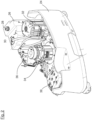
- the arrangement of the hydraulic fluid tank 26 on the carrier 24 is in Figure 2 shown.
- the hydraulic fluid tank 26 has a filling opening with a screw cap 28 on its top.
- a return line 30 also opens into the hydraulic fluid tank 26 on the top of the hydraulic fluid tank 26.
- the support 24 is shown without the components attached to it.
- the receptacles 40 are circular cylindrical recesses that were produced during the manufacture of the carrier 24 using a casting process.
- corresponding receptacles 40 can also be introduced, for example, by milling or drilling.
- the four receptacles 40 are located in a horizontally arranged plane.
- Three of the receptacles 40 are formed in a web 44 running around an outer edge of the carrier 24, a fourth of the receptacles 40 is located at a distance from the web 44 on a separate bulge 46 of the carrier 24.
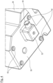
- Figure 4 shows a lower part of the hydraulic fluid tank 26 in a perspective view.
- a base surface 50 is formed on the underside of the hydraulic fluid tank 26, from which the four feet 42 protrude downwards.
- the feet 42 are circular cylindrical and consist of nitrile rubber.
- the hydraulic fluid tank 26 has a downward-facing, box-shaped bulge 52 with a nozzle 54 for attaching a drain hose on its underside.
- This bulge 52 with nozzle 54 and connected drain hose finds space in the free space 46 (see Figure 3 ).
- the feet 42 are dimensioned such that they essentially completely fill the receptacles 40 when they are inserted therein.
- Figure 5 shows the hydraulic fluid tank 26 in a vertical section plane that runs through the screw cap 28 and two of the feet 42. You can also see the carrier 24 with two of the receptacles 40, into each of which one of the feet 42 is inserted. Also clearly visible in Fig. 5 It can be seen that the bottom surface 50 as well as the side surfaces of the hydraulic fluid tank 26 have a distance of the adjacent elements of the industrial truck, in particular the carrier 24.
- the feet 42 are also inserted into recesses 56 in a base 58 of the hydraulic fluid tank 26 and are thus fastened to the hydraulic fluid tank 26.
- the wall of the hydraulic fluid tank 26 has a substantially uniform thickness.
Landscapes
- Engineering & Computer Science (AREA)
- Transportation (AREA)
- Structural Engineering (AREA)
- Civil Engineering (AREA)
- Life Sciences & Earth Sciences (AREA)
- Geology (AREA)
- Mechanical Engineering (AREA)
- Chemical & Material Sciences (AREA)
- Combustion & Propulsion (AREA)
- Supply Devices, Intensifiers, Converters, And Telemotors (AREA)
Description
- Die Erfindung betrifft ein Flurförderzeug mit einem Hydraulikflüssigkeitstank. Derartige Tanks nehmen eine Hydraulikflüssigkeit zum Betrieb der hydraulischen Komponenten des Flurförderzeugs auf, insbesondere einer hydraulisch angetriebenen Hubeinrichtung. Der Hydraulikflüssigkeitstank muss eine hohe Sicherheit gegen ein unerwünschtes Austreten der Hydraulikflüssigkeit bieten und, in Anbetracht der im Betrieb des Fahrzeugs auftretenden Beschleunigungen und Erschütterungen, sicher und vor äußeren Einwirkungen geschützt im Flurförderzeug befestigt sein.
- Der Hydraulikflüssigkeitstank weist ein erhebliches Volumen auf, das die Hydraulikflüssigkeit aufnimmt und das von einer zumeist relativ dünnen Wandung umschlossen ist. An den Hydraulikflüssigkeitstank angeschlossene Hydraulikleitungen sind gegenüber der Wandung abgedichtet.
- Zur Befestigung derartiger Hydraulikflüssigkeitstanks im Flurförderzeug sind zwei unterschiedliche Lösungen bekannt geworden. Bei einer ersten Lösung wird der Hydraulikflüssigkeitstank mit einer Schelle oder einer ähnlichen Halterung an einem Träger des Flurförderzeugs befestigt. Die Schelle oder sonstige Halterung umschließt einen Teil des Hydraulikflüssigkeitstanks und verspannt den Hydraulikflüssigkeitstank mit dem Träger. Dadurch wird der Hydraulikflüssigkeitstank relativ zu dem Träger fixiert, so dass er im Betrieb des Flurförderzeugs nicht verrutschen kann.
- Bei einer zweiten Lösung ist der Hydraulikflüssigkeitstank zumindest teilweise von einem hierfür vorgesehenen Aufnahmeraum des Flurförderzeugs umgeben, wobei zwischen den dem Hydraulikflüssigkeitstank zugewandten Innenseiten des Aufnahmeraums und dem Hydraulikflüssigkeitstank Abstandshalter, zum Beispiel in Form von Moosgummiplatten, angeordnet sind. Auf diese Weise wird der Hydraulikflüssigkeitstank in dem Aufnahmeraum gegen ein Verrutschen gesichert.
- Aus
DE 10 2011 004 596 A1 ist ein Hydrauliktank eines Flurförderzeugs gemäß dem Oberbegriff des Anspruchs 1 bekannt, der sowohl an seiner Unterseite wie auch an seiner Oberseite über Halterungsformationen zur Lagerung und Befestigung des Tanks in einem Flurförderzeug verfügt. -
JP H 11 322 292 A - Davon ausgehend ist es die Aufgabe der Erfindung, ein Flurförderzeug zur Verfügung zu stellen, bei dem der Hydraulikflüssigkeitstank auf besonders einfache und dennoch sichere Weise befestigt ist.
- Diese Aufgabe wird gelöst durch das Flurförderzeug mit den Merkmalen des Anspruchs 1. Vorteilhafte Ausgestaltungen sind in den Unteransprüchen angegeben.
- Das Flurförderzeug hat einen Träger und einen Hydraulikflüssigkeitstank, wobei der Hydraulikflüssigkeitstank mehrere Standfüße und der Träger mehrere Aufnahmen aufweist, in die jeweils einer der Standfüße eingesetzt ist.
- Die Standfüße können an der Unterseite des Hydraulikflüssigkeitstanks angeordnet sein. Sie können von einer Bodenfläche des Hydraulikflüssigkeitstanks nach unten vorstehen. Es können mindestens drei Standfüße, aber auch vier oder mehr Standfüße vorhanden sein. Jedem Standfuß kann eine korrespondierend angeordnete Aufnahme des Trägers zugeordnet sein. Die Aufnahmen weisen jeweils einen Freiraum auf, beispielsweise in Form einer Aussparung oder einer Bohrung, die einen der Standfüße bzw. einen Teil davon aufnimmt.
- Zum Einbau des Hydraulikflüssigkeitstanks ist es ausreichend, den Hydraulikflüssigkeitstank mit seinen Standfüßen in einem dafür vorgesehenen Freiraum des Flurförderzeugs anzuordnen und die Standfüße in die Aufnahmen einzusetzen. Soll der Hydraulikflüssigkeitstank wieder ausgebaut werden, beispielsweise im Rahmen von Wartungsarbeiten, kann er ganz einfach nach oben entnommen werden, wobei die Standfüße wieder aus den Aufnahmen herausgezogen werden. Es wurde festgestellt, dass allein durch das Zusammenwirken der Standfüße mit den Aufnahmen eine hinreichende Befestigung des Hydraulikflüssigkeitstanks erreicht wird. Der zwischen jedem der Standfüße und der zugehörigen Aufnahme zustandekommende Formschluss verhindert zuverlässig ein Verrutschen des Hydraulikflüssigkeitstanks in seitlicher Richtung. Eine zusätzliche Fixierung des Hydraulikflüssigkeitstanks in vertikaler Richtung hat sich als entbehrlich herausgestellt. Selbst bei stärkerer Beschleunigung oder bei Stößen, wie sie etwa beim Überfahren einer Schwelle auftreten können, verbleibt der Hydraulikflüssigkeitstank in seiner Einbauposition.
- Über die besondere Einfachheit der Befestigung in konstruktiver Hinsicht und mit Blick auf den Ein- oder Ausbau hinaus ermöglicht das Zusammenwirken der Standfüße mit den Aufnahmen eine besonders genaue Positionierung des Hydraulikflüssigkeitstanks an der vorgesehenen Einbauposition. Dies trägt dazu bei, dass am Hydraulikflüssigkeitstank ausgebildete oder damit verbundene Elemente, beispielsweise ein Einfüllstutzen für ein Auffüllen des Hydraulikflüssigkeitstanks, relativ zu dem Träger ebenfalls exakt positioniert sind. Dies ist von Vorteil, wenn diese Elemente mit weiteren Bauteilen des Flurförderzeugs zusammenwirken, etwa mit einer für den Einfüllstutzen vorgesehenen Öffnung in einer Abdeckung, deren Position relativ zu dem Träger fest vorgegeben ist. Grund für die verbesserte Positioniergenauigkeit ist, dass die Anordnung des Hydraulikflüssigkeitstanks unabhängig von gesondert zu montierenden Abstandshaltern oder Schellen/Halterungen ist. Anders als bei diesen bekannten Befestigungslösungen kommt es bei der Montage des Hydraulikflüssigkeitstanks auch nicht zu einer Verformung des Hydraulikflüssigkeitstanks, die einer exakten Anordnung beispielsweise eines Einfüllstutzens entgegenwirken kann.
- In einer Ausgestaltung besteht der Hydraulikflüssigkeitstank aus Kunststoff und ist in einem Spritzgieß- oder Rotationssinterverfahren hergestellt. Bei einem Rotationssinterverfahren, das auch als Rotationsschmelzverfahren bezeichnet wird, wird ein Kunststoffgranulat in einer Gegenform aufgeschmolzen und die Gegenform wird rotiert, zumeist um unterschiedliche Drehachsen, bis das Kunststoffmaterial nach Abkühlung erstarrt ist. Mit beiden Herstellungsverfahren ist eine kostengünstige Fertigung des Hydraulikflüssigkeitstanks möglich. Insbesondere hinsichtlich der möglichen Formgebung und Wandstärken gibt es jedoch Beschränkungen. Beispielsweise ist es im Rotationssinterverfahren nicht ohne weiteres möglich, Abschnitte der Wandung mit einer vergrößerten Wandstärke herzustellen. Daraus ergeben sich Einschränkungen hinsichtlich der Formstabilität des Hydraulikflüssigkeitstanks, die die Befestigung beispielsweise mit einer Schelle erschweren können. Für die bei der Erfindung vorgesehene Befestigung mithilfe von Standfüßen sind diese Beschränkungen jedoch nicht relevant.
- In einer Ausgestaltung sind die Aufnahmen in einer horizontalen Schnittebene vollständig von den Standfüßen ausgefüllt. Dadurch wird ein seitliches Verrutschen des Standfußes relativ zu der Aufnahme in horizontaler Richtung verhindert. Es entsteht eine in der horizontalen Ebene in allen Richtungen wirkende, formschlüssige Verbindung. Insgesamt gelingt eine besonders gute Fixierung des Hydraulikflüssigkeitstanks. Die Aufnahmen und/oder die Standfüße können in der horizontalen Schnittebene grundsätzlich eine beliebige Form aufweisen, beispielsweise quadratisch oder rechteckig. Vorteilhaft ist insbesondere ein kreisförmiger Querschnitt.
- In einer Ausgestaltung sind die Aufnahmen und/oder die Standfüße zylindrisch. Insbesondere können sie zum Beispiel kreiszylindrisch sein. Eine konische Ausbildung ist ebenfalls möglich.
- Bei der Erfindung stehen die Standfüße von einer Bodenfläche des Hydraulikflüssigkeitstanks nach unten vor, wobei die Bodenfläche überall in einem Abstand von dem Träger angeordnet ist. Wahlweise können auch alle sonstigen Flächen, insbesondere die Seitenflächen, des Hydraulikflüssigkeitstanks einen Abstand zu den benachbarten Komponenten des Flurförderzeugs einhalten. Dadurch werden Beschädigungen im Bereich der genannten Flächen vermieden, die anderenfalls beispielsweise bei Vibrationen auftreten können, wenn eine der Flächen sich zum Beispiel an einer Schweißperle eines benachbart angeordneten Blechs reibt.
- In einer Ausgestaltung sind in einer Bodenfläche des Hydraulikflüssigkeitstanks Aussparungen ausgebildet, in die die Standfüße eingesetzt sind. Dadurch können die Standfüße durch einfaches Einsetzen in die Aussparungen besonders einfach an dem Hydraulikflüssigkeitstank befestigt werden. Die Abmessungen der Aussparungen können so auf die Standfüße abgestimmt sein, dass die Standfüße nach dem Einpressen in die Aussparungen sicher fixiert sind. Geeignete Aussparungen, beispielsweise kreiszylindrische Vertiefungen, sind durch entsprechende Formgebung der Wandung des Hydraulikflüssigkeitstanks einfach herstellbar, insbesondere mit den bereits genannten Herstellungsverfahren. Eine Vergrößerung der Wandstärke ist hierfür nicht unbedingt erforderlich.
- In einer Ausgestaltung sind in einem Boden des Hydraulikflüssigkeitstanks Gewindeeinsätze angeordnet, mit denen die Standfüße verschraubt sind. Beispielsweise können Gewindeeinsätze aus Metall verwendet werden, die bereits bei der Herstellung des Hydraulikflüssigkeitstanks in dessen Wandung integriert werden. Ebenfalls möglich ist, die Gewindeeinsätze in geeignete Aussparungen einzupressen oder sie darin zu verkleben. Die Standfüße können einteilig mit einem Außengewinde gefertigt oder mit einem gesonderten Gewindebolzen versehen werden, der in den Gewindeeinsatz eingeschraubt wird, um den Standfuß zu befestigen.
- In einer Ausgestaltung bestehen die Standfüße aus einem elastischen Material. Das elastische Material erlaubt eine Verformung der Standfüße. Dadurch wird ein einfaches Einsetzen des Hydraulikflüssigkeitstanks mit sämtlichen Standfüßen in die korrespondierenden Aufnahmen auch bei Fertigungstoleranzen möglich. Außerdem kann bei entsprechender Einpassung der Standfüße in die Aufnahmen ein zusätzlicher Kraftschluss erzielt werden. Schließlich erlaubt eine hinreichende Elastizität der Standfüße eine Schwingungsisolation des Hydraulikflüssigkeitstanks. Ein besonders geeignetes, elastisches Material für die Standfüße ist Nitrilkautschuk, auch bezeichnet als NBR für nitrile butadiene rubber (Acrylnitril-Butadien-Kautschuk).
- In einer Ausgestaltung sind die Standfüße einteilig mit dem Hydraulikflüssigkeitstank hergestellt. Sie bestehen in diesem Fall also aus demselben Material wie der Hydraulikflüssigkeitstank, insbesondere aus einem Kunststoffmaterial. Beispielsweise können bei der Herstellung des Hydraulikflüssigkeitstanks in einem der bereits erläuterten Verfahren ohne weiteres entsprechende Standfüße angeformt werden.
- In einer Ausgestaltung ist an einer Unterseite des Hydraulikflüssigkeitstanks eine nach unten weisende Ausbuchtung mit einem Ablaufschlauch angeordnet, wobei die Ausbuchtung in seitlicher Richtung zwischen den Standfüßen und unterhalb einer Ebene angeordnet ist, in der sich die Standfüße befinden. Dadurch ergibt sich ein sicherer Stand des Hydraulikflüssigkeitstanks mit einer optimal positionierten Entnahmestelle an einem tiefstgelegenen Punkt etwa in einer Mitte des Hydraulikflüssigkeitstanks. Der Zugang zu der Entnahmestelle wird insbesondere nicht durch den Träger eingeschränkt.
- In einer Ausgestaltung ist der Träger Teil eines Fahrzeuggrundrahmens. Grundsätzlich kann der Träger eine beliebige Tragstruktur für die Befestigung des Hydraulikflüssigkeitstanks sein, beispielsweise ein Zwischenboden oder ein mit dem Fahrzeuggrundrahmen verschraubter oder verschweißter Profilträger. Der Träger kann auch von mehreren Elementen gebildet sein, die miteinander verbunden und/oder an einer sonstigen Tragstruktur des Flurförderzeugs befestigt sind. Ein besonders einfacher Aufbau ergibt sich, wenn der Träger Teil eines Fahrzeuggrundrahmens ist, also kein gesonderter Träger für den Hydraulikflüssigkeitstank erforderlich ist. Insbesondere kann es sich bei dem Träger um eine Fahrzeuggrundrahmenkomponente aus Gusseisen handeln.
- Nachfolgend wird die Erfindung anhand von Figuren näher erläutert. Es zeigen:
- Fig. 1
- ein Flurförderzeug in einer perspektivischen Ansicht,
- Fig. 2
- einen Träger des Flurförderzeugs aus
Figur 1 mit eingebautem Hydraulikflüssigkeitstank in einer perspektivischen Ansicht, - Fig. 3
- den Träger aus
Figur 2 in einer anderen perspektivischen Ansicht, - Fig. 4
- eine perspektivische Ansicht eines unteren Teils des Hydraulikflüssigkeitstanks aus
Figur 2 , - Fig. 5
- den Hydraulikflüssigkeitstank aus
Figur 2 in einer Schnittdarstellung. - Das Flurförderzeug aus
Fig. 1 ist ein Schubmaststapler mit zwei Radarmen 10, an deren vorderen Enden jeweils ein Lastrad 12 angeordnet ist. Zwischen den beiden Radarmen 10 befindet sich ein verschieblich angeordnetes Hubgerüst 14 mit einer Lastgabel 16. Außerdem hat der Schubmaststapler eine Fahrerkabine 18, in der Fahrersitz 20 angeordnet ist. An der Unterseite des Schubmaststaplers erkennt man ein lenkbares Antriebsrad 22. Der Fahrzeuggrundrahmen des Schubmaststaplers umfasst einen Träger 24, der aus Gusseisen hergestellt ist und zugleich ein Gegengewicht bildet. Der inFig 1 verdeckte Hydraulikflüssigkeitstank 26 ist etwa unterhalb des Fahrersitzes 20 angeordnet. - Die Anordnung des Hydraulikflüssigkeitstanks 26 an dem Träger 24 ist in
Figur 2 gezeigt. Der Hydraulikflüssigkeitstank 26 weist an seiner Oberseite eine Befüllöffnung mit einem Schraubverschluss 28 auf. Ebenfalls an der Oberseite des Hydraulikflüssigkeitstanks 26 mündet eine Rückführleitung 30 in den Hydraulikflüssigkeitstank 26. - Weitere Komponenten des Schubmaststaplers sind ebenfalls an dem Träger 24 befestigt. Hierzu zählen ein Hydraulikmotor 32, ein Fahrantriebsmotor 34 und ein Lenkmotor 36. Bei allen drei Motoren handelt es sich um Elektromotoren. Weiterhin ist in
Figur 2 eine elektronische Steuerung 38 des Schubmaststaplers erkennbar, die ebenfalls an dem Träger 24 befestigt ist. - In
Figur 3 ist der Träger 24 ohne die daran befestigten Komponenten dargestellt. Man erkennt dort vier an dem Träger ausgebildete Aufnahmen 40, in die die Stützfüße 42 (sieheFigur 4 ) des Hydraulikflüssigkeitstanks 26 eingesetzt werden. Im Beispiel handelt es sich bei den Aufnahmen 40 und kreiszylindrische Vertiefungen, die bei der Herstellung des Trägers 24 im Gießverfahren hergestellt worden sind. Alternativ können entsprechende Aufnahmen 40 auch zum Beispiel durch Fräsen oder Bohren eingebracht werden. Die vier Aufnahmen 40 liegen in einer horizontal angeordneten Ebene. Drei der Aufnahmen 40 sind in einem an einem äußeren Rand des Trägers 24 umlaufenden Steg 44 ausgebildet, eine vierte der Aufnahmen 40 befindet sich in einem Abstand von dem Steg 44 an einer gesonderten Ausbuchtung 46 des Trägers 24. Zwischen den vier Aufnahmen 40 und unterhalb der Ebene, in der die Aufnahmen 40 angeordnet sind, befindet sich ein Freiraum 48. -
Figur 4 zeigt einen unteren Teil des Hydraulikflüssigkeitstanks 26 in einer perspektivischen Ansicht. An der Unterseite des Hydraulikflüssigkeitstanks 26 ist eine Bodenfläche 50 ausgebildet, aus der die vier Standfüße 42 nach unten hervorstehen. Die Standfüße 42 sind kreiszylindrisch und bestehen aus Nitrilkautschuk. - Zwischen den Standfüßen 42 weist der Hydraulikflüssigkeitstank 26 an seiner Unterseite eine nach unten weisende, kastenförmige Ausbuchtung 52 mit einem Stutzen 54 zur Befestigung eines Ablaufschlauchs auf. Diese Ausbuchtung 52 mit Stutzen 54 und daran angeschlossenem Ablaufschlauch findet Platz in dem Freiraum 46 (siehe
Figur 3 ). Die Standfüße 42 sind so bemessen, dass sie die Aufnahmen 40 im Wesentlichen vollständig ausfüllen, wenn sie in diese eingesetzt sind. -
Figur 5 zeigt den Hydraulikflüssigkeitstank 26 in einer vertikalen Schnittebene, die durch den Schraubverschluss 28 und zwei der Standfüße 42 verläuft. Man erkennt außerdem den Träger 24 mit zwei der Aufnahmen 40, in die jeweils einer der Standfüße 42 eingesetzt ist. Ebenfalls gut inFig. 5 erkennbar ist, dass die Bodenfläche 50 ebenso wie seitliche Flächen des Hydraulikflüssigkeitstanks 26 einen Abstand von den benachbarten Elementen des Flurförderzeugs, insbesondere von dem Träger 24, einhalten. - Die Standfüße 42 sind außerdem in Aussparungen 56 in einem Boden 58 des Hydraulikflüssigkeitstanks 26 eingesetzt und auf diese Weise an dem Hydraulikflüssigkeitstank 26 befestigt. Die Wandung des Hydraulikflüssigkeitstanks 26 weist eine im Wesentlichen gleichmäßige Stärke auf.
-
- 10
- Radarm
- 12
- Lastrad
- 14
- Hubgerüst
- 16
- Lastgabel
- 18
- Fahrerkabine
- 20
- Fahrersitz
- 22
- Antriebsrad
- 24
- Träger
- 26
- Hydraulikflüssigkeitstank
- 28
- Schraubverschluss
- 30
- Rückführleitung
- 32
- Hydraulikmotor
- 34
- Fahrantriebsmotor
- 36
- Lenkmotor
- 38
- elektronische Steuerung
- 40
- Aufnahme
- 42
- Standfuß
- 44
- Steg
- 26
- Ausbuchtung
- 48
- Freiraum
- 50
- Bodenfläche
- 52
- Ausbuchtung
- 54
- Stutzen
- 56
- Aussparung
- 58
- Boden
Claims (10)
- Flurförderzeug mit einem Träger (24) und einem Hydraulikflüssigkeitstank (26), wobei der Hydraulikflüssigkeitstank (26) mehrere Standfüße (42) aufweist, dadurch gekennzeichnet, dass der Träger (24) mehrere Aufnahmen (40) aufweist, in die jeweils einer der Standfüße (42) eingesetzt ist, wobei die Standfüße (42) von einer Bodenfläche (50) des Hydraulikflüssigkeitstanks (26) nach unten vorstehen, die Bodenfläche (50) überall in einem Abstand von dem Träger (24) angeordnet ist und zwischen jedem der Standfüße (42) und der zugehörigen Aufnahme (40) ein Formschluss besteht.
- Flurförderzeug nach Anspruch 1, dadurch gekennzeichnet, dass der Hydraulikflüssigkeitstank (26) aus Kunststoff besteht und in einem Spritzgieß- oder Rotationssinterverfahren hergestellt ist.
- Flurförderzeug nach Anspruch 1 oder 2, dadurch gekennzeichnet, dass die Aufnahmen (40) in einer horizontalen Schnittebene vollständig von den Standfüßen (42) ausgefüllt sind.
- Flurförderzeug nach einem der Ansprüche 1 bis 3, dadurch gekennzeichnet, dass die Aufnahmen (40) und/oder die Standfüße (42) zylindrisch sind.
- Flurförderzeug nach einem der Ansprüche 1 bis 4, dadurch gekennzeichnet, dass in einer Bodenfläche (50) des Hydraulikflüssigkeitstanks (26) Aussparungen (56) ausgebildet sind, in die die Standfüße (42) eingesetzt sind.
- Flurförderzeug nach einem der Ansprüche 1 bis 5, dadurch gekennzeichnet, dass in einem Boden (58) des Hydraulikflüssigkeitstanks (26) Gewindeeinsätze angeordnet sind, mit denen die Standfüße (42) verschraubt sind.
- Flurförderzeug nach einem der Ansprüche 1 bis 6, dadurch gekennzeichnet, dass die Standfüße (42) aus einem elastischen Material bestehen.
- Flurförderzeug nach einem der Ansprüche 1 bis 4, dadurch gekennzeichnet, dass die Standfüße (42) einteilig mit dem Hydraulikflüssigkeitstank (26) hergestellt sind.
- Flurförderzeug nach einem der Ansprüche 1 bis 8, dadurch gekennzeichnet, dass an einer Unterseite des Hydraulikflüssigkeitstanks (26) eine nach unten weisende Ausbuchtung (52) mit einem Ablaufschlauch angeordnet ist, wobei die Ausbuchtung (52) in seitlicher Richtung zwischen den Standfüßen (42) und unterhalb einer Ebene angeordnet ist, in der sich die Standfüße (42) befinden.
- Flurförderzeug nach einem der Ansprüche 1 bis 9, dadurch gekennzeichnet, dass der Träger (24) Teil eines Fahrzeuggrundrahmens ist.
Applications Claiming Priority (1)
| Application Number | Priority Date | Filing Date | Title |
|---|---|---|---|
| DE102018105009.7A DE102018105009A1 (de) | 2018-03-05 | 2018-03-05 | Flurförderzeug mit einem Hydraulikflüssigkeitstank |
Publications (2)
| Publication Number | Publication Date |
|---|---|
| EP3536653A1 EP3536653A1 (de) | 2019-09-11 |
| EP3536653B1 true EP3536653B1 (de) | 2025-01-22 |
Family
ID=65628710
Family Applications (1)
| Application Number | Title | Priority Date | Filing Date |
|---|---|---|---|
| EP19159787.1A Active EP3536653B1 (de) | 2018-03-05 | 2019-02-27 | Flurförderzeug mit einem hydraulikflüssigkeitstank |
Country Status (4)
| Country | Link |
|---|---|
| US (1) | US11021354B2 (de) |
| EP (1) | EP3536653B1 (de) |
| CN (1) | CN110228771B (de) |
| DE (1) | DE102018105009A1 (de) |
Families Citing this family (1)
| Publication number | Priority date | Publication date | Assignee | Title |
|---|---|---|---|---|
| US20240240658A1 (en) * | 2023-01-17 | 2024-07-18 | Narendra Gupta | Hydraulic power pack module |
Family Cites Families (19)
| Publication number | Priority date | Publication date | Assignee | Title |
|---|---|---|---|---|
| US1039098A (en) * | 1911-08-14 | 1912-09-24 | Howard E Coffin | Tank for motor-vehicles. |
| US1611906A (en) * | 1925-05-27 | 1926-12-28 | Int Motor Co | Tank support |
| DE8608045U1 (de) * | 1986-03-22 | 1986-05-15 | Boese, Manfred, 5630 Remscheid | Hydraulikflüssigkeitsbehälter |
| JPH06191297A (ja) * | 1992-12-28 | 1994-07-12 | Toyota Autom Loom Works Ltd | 産業車両用オイルタンク及びオイルタンクの取付構造 |
| JPH11322292A (ja) * | 1998-05-20 | 1999-11-24 | Mitsubishi Heavy Ind Ltd | フォークリフトの油圧タンクの取付構造 |
| AT4282U1 (de) * | 2000-01-26 | 2001-05-25 | Tesma Motoren Getriebetechnik | Treibstoffbehälter für kraftfahrzeuge |
| US6886861B2 (en) * | 2003-02-19 | 2005-05-03 | General Motors Corporation | Trunk mounted fuel tank assembly |
| US6875258B2 (en) * | 2003-04-09 | 2005-04-05 | Ti Group Automotive Systems, L.L.C. | Fuel tank assembly |
| JP4681257B2 (ja) * | 2004-06-03 | 2011-05-11 | 株式会社ニフコ | 保護板取付構造 |
| US7497290B2 (en) * | 2006-07-21 | 2009-03-03 | Gm Global Technology Operations, Inc. | Fuel tank shield with cushion |
| JP4473902B2 (ja) * | 2007-09-10 | 2010-06-02 | 本田技研工業株式会社 | 防振部材の取付構造 |
| DE102011004596A1 (de) * | 2010-12-13 | 2012-06-21 | Jungheinrich Aktiengesellschaft | Hydrauliktank für ein Flurförderzeug |
| DE102011009636A1 (de) * | 2011-01-27 | 2012-08-02 | GM Global Technology Operations LLC (n. d. Ges. d. Staates Delaware) | Anordnung zur Befestigung eines Kraftstoffbehälters an einer Fahrzeugkarosserie |
| JP5331142B2 (ja) * | 2011-03-01 | 2013-10-30 | 八千代工業株式会社 | 燃料タンクにおける緩衝部材の取付構造 |
| JP5847769B2 (ja) * | 2012-12-18 | 2016-01-27 | 八千代工業株式会社 | 燃料タンク用緩衝部材 |
| JP2014148227A (ja) * | 2013-01-31 | 2014-08-21 | Yachiyo Industry Co Ltd | 燃料タンクの車体取付構造 |
| CN206035691U (zh) * | 2016-08-26 | 2017-03-22 | 盐城市建龙机电设备制造有限公司 | 防堵柴油机油箱 |
| CN206099105U (zh) * | 2016-08-31 | 2017-04-12 | 安徽宸瑞节能环保科技工程有限公司 | 一种用于户外配电箱的拼装式支撑底座 |
| CN106882497A (zh) * | 2017-04-10 | 2017-06-23 | 成都大漠石油技术有限公司 | 便于取样的石油储存装置 |
-
2018
- 2018-03-05 DE DE102018105009.7A patent/DE102018105009A1/de active Pending
-
2019
- 2019-02-27 EP EP19159787.1A patent/EP3536653B1/de active Active
- 2019-03-04 US US16/291,072 patent/US11021354B2/en active Active
- 2019-03-05 CN CN201910161897.9A patent/CN110228771B/zh active Active
Also Published As
| Publication number | Publication date |
|---|---|
| DE102018105009A1 (de) | 2019-09-05 |
| US11021354B2 (en) | 2021-06-01 |
| US20190270628A1 (en) | 2019-09-05 |
| CN110228771A (zh) | 2019-09-13 |
| EP3536653A1 (de) | 2019-09-11 |
| CN110228771B (zh) | 2023-03-28 |
Similar Documents
| Publication | Publication Date | Title |
|---|---|---|
| EP3710342B1 (de) | Seitenschwelleranordnung einer karosserie eines elektrisch betreibbaren kraftwagens | |
| DE602005004913T2 (de) | Anordnung für eine fahrzeugseitenverkleidung und fahrzeug mit einer solchen seitenverkleidung | |
| DE60105948T4 (de) | Trägerstruktur für Kfz-Kühleranordnung | |
| DE102017217931B4 (de) | Karosseriestruktur für ein zweispuriges Fahrzeug | |
| DE102008059680A1 (de) | Vorrichtung zur Halterung einer Batterie | |
| DE19603957C2 (de) | Oberer Querträger eines Fahrzeug-Frontendteiles | |
| DE102011081784A1 (de) | Energie absorbierende Windlaufstruktur | |
| DE19738803B4 (de) | Gehäuse für ein Gerät, insbesondere Sensor für Kraftfahrzeuge | |
| DE102009015637A1 (de) | Fahrzeug | |
| DE102010025260B4 (de) | Traggestell zur seitlichen Befestigung von Anbauteilen an einem Längsträger einer Nutzfahrzeug-Tragstruktur | |
| DE19714356C5 (de) | Einbau-Konstruktion für Airbags im Auto | |
| DE4424191B4 (de) | Abdeckung, insbesondere Modul- oder Bausteinabdeckung, für eine Luft- oder Gassackeinrichtung | |
| DE10316952A1 (de) | Sicherheitsvorrichtung für ein Kraftfahrzeug mit einer Vorbaustruktur | |
| DE102008057379A1 (de) | Anordnung einer Aufnahme für ein Abschleppmittel | |
| DE10324270A1 (de) | Sicherheitsvorrichtung für eine Kraftwagen-Rohbaustruktur | |
| EP3536653B1 (de) | Flurförderzeug mit einem hydraulikflüssigkeitstank | |
| DE19930700C2 (de) | Halterung für einen Kotflügel mit einem integrierten Stoßfänger an einem Befestigungsabschnitt einer Rohbaukarosserie | |
| EP1316479A2 (de) | Stossfängerhalter und Stossfänger für Kraftfahrzeuge | |
| EP3668776B1 (de) | Vorbaustrukturanordnung für einen kraftwagenrohbau sowie aggregateträger für eine derartige vorbaustrukturanordnung | |
| DE202020107582U1 (de) | Cockpitquerträgeranordnung | |
| EP1084935A2 (de) | Hilfsrahmenanordnung für einen Fahrzeugaufbau zur Aufnahme von Crashenergie | |
| DE19752073B4 (de) | Kraftfahrzeugkarosserie mit einem Strukturquerträger | |
| EP0098401A1 (de) | Antriebsaggregat für Kraftfahrzeuge | |
| DE10316403A1 (de) | Schubmaststapler | |
| DE102004025245A1 (de) | Hybridquerträger für Kraftfahrzeuge |
Legal Events
| Date | Code | Title | Description |
|---|---|---|---|
| PUAI | Public reference made under article 153(3) epc to a published international application that has entered the european phase |
Free format text: ORIGINAL CODE: 0009012 |
|
| STAA | Information on the status of an ep patent application or granted ep patent |
Free format text: STATUS: THE APPLICATION HAS BEEN PUBLISHED |
|
| AK | Designated contracting states |
Kind code of ref document: A1 Designated state(s): AL AT BE BG CH CY CZ DE DK EE ES FI FR GB GR HR HU IE IS IT LI LT LU LV MC MK MT NL NO PL PT RO RS SE SI SK SM TR |
|
| AX | Request for extension of the european patent |
Extension state: BA ME |
|
| STAA | Information on the status of an ep patent application or granted ep patent |
Free format text: STATUS: REQUEST FOR EXAMINATION WAS MADE |
|
| 17P | Request for examination filed |
Effective date: 20200227 |
|
| RBV | Designated contracting states (corrected) |
Designated state(s): AL AT BE BG CH CY CZ DE DK EE ES FI FR GB GR HR HU IE IS IT LI LT LU LV MC MK MT NL NO PL PT RO RS SE SI SK SM TR |
|
| STAA | Information on the status of an ep patent application or granted ep patent |
Free format text: STATUS: EXAMINATION IS IN PROGRESS |
|
| 17Q | First examination report despatched |
Effective date: 20221221 |
|
| P01 | Opt-out of the competence of the unified patent court (upc) registered |
Effective date: 20230628 |
|
| GRAP | Despatch of communication of intention to grant a patent |
Free format text: ORIGINAL CODE: EPIDOSNIGR1 |
|
| STAA | Information on the status of an ep patent application or granted ep patent |
Free format text: STATUS: GRANT OF PATENT IS INTENDED |
|
| INTG | Intention to grant announced |
Effective date: 20241111 |
|
| GRAS | Grant fee paid |
Free format text: ORIGINAL CODE: EPIDOSNIGR3 |
|
| GRAA | (expected) grant |
Free format text: ORIGINAL CODE: 0009210 |
|
| STAA | Information on the status of an ep patent application or granted ep patent |
Free format text: STATUS: THE PATENT HAS BEEN GRANTED |
|
| AK | Designated contracting states |
Kind code of ref document: B1 Designated state(s): AL AT BE BG CH CY CZ DE DK EE ES FI FR GB GR HR HU IE IS IT LI LT LU LV MC MK MT NL NO PL PT RO RS SE SI SK SM TR |
|
| REG | Reference to a national code |
Ref country code: GB Ref legal event code: FG4D Free format text: NOT ENGLISH |
|
| REG | Reference to a national code |
Ref country code: CH Ref legal event code: EP |
|
| REG | Reference to a national code |
Ref country code: IE Ref legal event code: FG4D Free format text: LANGUAGE OF EP DOCUMENT: GERMAN |
|
| REG | Reference to a national code |
Ref country code: DE Ref legal event code: R096 Ref document number: 502019012838 Country of ref document: DE |
|
| REG | Reference to a national code |
Ref country code: SE Ref legal event code: TRGR |
|
| REG | Reference to a national code |
Ref country code: NL Ref legal event code: MP Effective date: 20250122 |
|
| PG25 | Lapsed in a contracting state [announced via postgrant information from national office to epo] |
Ref country code: NL Free format text: LAPSE BECAUSE OF FAILURE TO SUBMIT A TRANSLATION OF THE DESCRIPTION OR TO PAY THE FEE WITHIN THE PRESCRIBED TIME-LIMIT Effective date: 20250122 |
|
| PG25 | Lapsed in a contracting state [announced via postgrant information from national office to epo] |
Ref country code: RS Free format text: LAPSE BECAUSE OF FAILURE TO SUBMIT A TRANSLATION OF THE DESCRIPTION OR TO PAY THE FEE WITHIN THE PRESCRIBED TIME-LIMIT Effective date: 20250422 |
|
| PG25 | Lapsed in a contracting state [announced via postgrant information from national office to epo] |
Ref country code: FI Free format text: LAPSE BECAUSE OF FAILURE TO SUBMIT A TRANSLATION OF THE DESCRIPTION OR TO PAY THE FEE WITHIN THE PRESCRIBED TIME-LIMIT Effective date: 20250122 |
|
| PG25 | Lapsed in a contracting state [announced via postgrant information from national office to epo] |
Ref country code: PL Free format text: LAPSE BECAUSE OF FAILURE TO SUBMIT A TRANSLATION OF THE DESCRIPTION OR TO PAY THE FEE WITHIN THE PRESCRIBED TIME-LIMIT Effective date: 20250122 |
|
| PG25 | Lapsed in a contracting state [announced via postgrant information from national office to epo] |
Ref country code: ES Free format text: LAPSE BECAUSE OF FAILURE TO SUBMIT A TRANSLATION OF THE DESCRIPTION OR TO PAY THE FEE WITHIN THE PRESCRIBED TIME-LIMIT Effective date: 20250122 |
|
| REG | Reference to a national code |
Ref country code: LT Ref legal event code: MG9D |
|
| PG25 | Lapsed in a contracting state [announced via postgrant information from national office to epo] |
Ref country code: IS Free format text: LAPSE BECAUSE OF FAILURE TO SUBMIT A TRANSLATION OF THE DESCRIPTION OR TO PAY THE FEE WITHIN THE PRESCRIBED TIME-LIMIT Effective date: 20250522 Ref country code: NO Free format text: LAPSE BECAUSE OF FAILURE TO SUBMIT A TRANSLATION OF THE DESCRIPTION OR TO PAY THE FEE WITHIN THE PRESCRIBED TIME-LIMIT Effective date: 20250422 |
|
| PG25 | Lapsed in a contracting state [announced via postgrant information from national office to epo] |
Ref country code: HR Free format text: LAPSE BECAUSE OF FAILURE TO SUBMIT A TRANSLATION OF THE DESCRIPTION OR TO PAY THE FEE WITHIN THE PRESCRIBED TIME-LIMIT Effective date: 20250122 |
|
| PG25 | Lapsed in a contracting state [announced via postgrant information from national office to epo] |
Ref country code: LV Free format text: LAPSE BECAUSE OF FAILURE TO SUBMIT A TRANSLATION OF THE DESCRIPTION OR TO PAY THE FEE WITHIN THE PRESCRIBED TIME-LIMIT Effective date: 20250122 Ref country code: PT Free format text: LAPSE BECAUSE OF FAILURE TO SUBMIT A TRANSLATION OF THE DESCRIPTION OR TO PAY THE FEE WITHIN THE PRESCRIBED TIME-LIMIT Effective date: 20250522 |
|
| PG25 | Lapsed in a contracting state [announced via postgrant information from national office to epo] |
Ref country code: GR Free format text: LAPSE BECAUSE OF FAILURE TO SUBMIT A TRANSLATION OF THE DESCRIPTION OR TO PAY THE FEE WITHIN THE PRESCRIBED TIME-LIMIT Effective date: 20250423 Ref country code: BG Free format text: LAPSE BECAUSE OF FAILURE TO SUBMIT A TRANSLATION OF THE DESCRIPTION OR TO PAY THE FEE WITHIN THE PRESCRIBED TIME-LIMIT Effective date: 20250122 |
|
| REG | Reference to a national code |
Ref country code: CH Ref legal event code: PL |
|
| PG25 | Lapsed in a contracting state [announced via postgrant information from national office to epo] |
Ref country code: SM Free format text: LAPSE BECAUSE OF FAILURE TO SUBMIT A TRANSLATION OF THE DESCRIPTION OR TO PAY THE FEE WITHIN THE PRESCRIBED TIME-LIMIT Effective date: 20250122 |
|
| PG25 | Lapsed in a contracting state [announced via postgrant information from national office to epo] |
Ref country code: DK Free format text: LAPSE BECAUSE OF FAILURE TO SUBMIT A TRANSLATION OF THE DESCRIPTION OR TO PAY THE FEE WITHIN THE PRESCRIBED TIME-LIMIT Effective date: 20250122 |
|
| PG25 | Lapsed in a contracting state [announced via postgrant information from national office to epo] |
Ref country code: MC Free format text: LAPSE BECAUSE OF FAILURE TO SUBMIT A TRANSLATION OF THE DESCRIPTION OR TO PAY THE FEE WITHIN THE PRESCRIBED TIME-LIMIT Effective date: 20250122 |
|
| PG25 | Lapsed in a contracting state [announced via postgrant information from national office to epo] |
Ref country code: LU Free format text: LAPSE BECAUSE OF NON-PAYMENT OF DUE FEES Effective date: 20250227 |
|
| PG25 | Lapsed in a contracting state [announced via postgrant information from national office to epo] |
Ref country code: CH Free format text: LAPSE BECAUSE OF NON-PAYMENT OF DUE FEES Effective date: 20250228 |
|
| PG25 | Lapsed in a contracting state [announced via postgrant information from national office to epo] |
Ref country code: EE Free format text: LAPSE BECAUSE OF FAILURE TO SUBMIT A TRANSLATION OF THE DESCRIPTION OR TO PAY THE FEE WITHIN THE PRESCRIBED TIME-LIMIT Effective date: 20250122 |
|
| REG | Reference to a national code |
Ref country code: DE Ref legal event code: R097 Ref document number: 502019012838 Country of ref document: DE |
|
| PG25 | Lapsed in a contracting state [announced via postgrant information from national office to epo] |
Ref country code: RO Free format text: LAPSE BECAUSE OF FAILURE TO SUBMIT A TRANSLATION OF THE DESCRIPTION OR TO PAY THE FEE WITHIN THE PRESCRIBED TIME-LIMIT Effective date: 20250122 |
|
| PG25 | Lapsed in a contracting state [announced via postgrant information from national office to epo] |
Ref country code: SK Free format text: LAPSE BECAUSE OF FAILURE TO SUBMIT A TRANSLATION OF THE DESCRIPTION OR TO PAY THE FEE WITHIN THE PRESCRIBED TIME-LIMIT Effective date: 20250122 |
|
| PLBE | No opposition filed within time limit |
Free format text: ORIGINAL CODE: 0009261 |
|
| STAA | Information on the status of an ep patent application or granted ep patent |
Free format text: STATUS: NO OPPOSITION FILED WITHIN TIME LIMIT |
|
| REG | Reference to a national code |
Ref country code: BE Ref legal event code: MM Effective date: 20250228 |
|
| GBPC | Gb: european patent ceased through non-payment of renewal fee |
Effective date: 20250422 |
|
| 26N | No opposition filed |
Effective date: 20251023 |
|
| PG25 | Lapsed in a contracting state [announced via postgrant information from national office to epo] |
Ref country code: GB Free format text: LAPSE BECAUSE OF NON-PAYMENT OF DUE FEES Effective date: 20250422 |
|
| PG25 | Lapsed in a contracting state [announced via postgrant information from national office to epo] |
Ref country code: BE Free format text: LAPSE BECAUSE OF NON-PAYMENT OF DUE FEES Effective date: 20250228 |
|
| PG25 | Lapsed in a contracting state [announced via postgrant information from national office to epo] |
Ref country code: IE Free format text: LAPSE BECAUSE OF NON-PAYMENT OF DUE FEES Effective date: 20250227 |
|
| PGFP | Annual fee paid to national office [announced via postgrant information from national office to epo] |
Ref country code: SE Payment date: 20260218 Year of fee payment: 8 |
|
| PGFP | Annual fee paid to national office [announced via postgrant information from national office to epo] |
Ref country code: DE Payment date: 20260217 Year of fee payment: 8 |
|
| PG25 | Lapsed in a contracting state [announced via postgrant information from national office to epo] |
Ref country code: AT Free format text: LAPSE BECAUSE OF NON-PAYMENT OF DUE FEES Effective date: 20250227 |
|
| PGFP | Annual fee paid to national office [announced via postgrant information from national office to epo] |
Ref country code: IT Payment date: 20260227 Year of fee payment: 8 |
|
| REG | Reference to a national code |
Ref country code: AT Ref legal event code: MM01 Ref document number: 1761359 Country of ref document: AT Kind code of ref document: T Effective date: 20250227 |
|
| PGFP | Annual fee paid to national office [announced via postgrant information from national office to epo] |
Ref country code: FR Payment date: 20260223 Year of fee payment: 8 |
|
| PGFP | Annual fee paid to national office [announced via postgrant information from national office to epo] |
Ref country code: CZ Payment date: 20260217 Year of fee payment: 8 |