EP3536575A2 - Appareil et procédé de commande d'évitement de collisions de véhicule - Google Patents
Appareil et procédé de commande d'évitement de collisions de véhicule Download PDFInfo
- Publication number
- EP3536575A2 EP3536575A2 EP19156899.7A EP19156899A EP3536575A2 EP 3536575 A2 EP3536575 A2 EP 3536575A2 EP 19156899 A EP19156899 A EP 19156899A EP 3536575 A2 EP3536575 A2 EP 3536575A2
- Authority
- EP
- European Patent Office
- Prior art keywords
- host vehicle
- vehicle
- collision
- risk
- avoidance
- Prior art date
- Legal status (The legal status is an assumption and is not a legal conclusion. Google has not performed a legal analysis and makes no representation as to the accuracy of the status listed.)
- Pending
Links
- 238000000034 method Methods 0.000 title claims abstract description 25
- 238000000926 separation method Methods 0.000 claims description 5
- 238000004891 communication Methods 0.000 description 43
- 230000005540 biological transmission Effects 0.000 description 21
- 238000001514 detection method Methods 0.000 description 13
- 230000008569 process Effects 0.000 description 8
- 230000003287 optical effect Effects 0.000 description 7
- 238000005516 engineering process Methods 0.000 description 6
- 238000010586 diagram Methods 0.000 description 4
- 238000003491 array Methods 0.000 description 3
- 230000008859 change Effects 0.000 description 3
- 230000000694 effects Effects 0.000 description 3
- 230000006870 function Effects 0.000 description 3
- DSGKWFGEUBCEIE-UHFFFAOYSA-N (2-carbonochloridoylphenyl) acetate Chemical compound CC(=O)OC1=CC=CC=C1C(Cl)=O DSGKWFGEUBCEIE-UHFFFAOYSA-N 0.000 description 1
- 238000002485 combustion reaction Methods 0.000 description 1
- 230000003247 decreasing effect Effects 0.000 description 1
- 239000000463 material Substances 0.000 description 1
- 238000010295 mobile communication Methods 0.000 description 1
- 238000012986 modification Methods 0.000 description 1
- 230000004048 modification Effects 0.000 description 1
- 230000010363 phase shift Effects 0.000 description 1
- 239000000758 substrate Substances 0.000 description 1
- 230000000007 visual effect Effects 0.000 description 1
Images


Classifications
-
- B—PERFORMING OPERATIONS; TRANSPORTING
- B60—VEHICLES IN GENERAL
- B60W—CONJOINT CONTROL OF VEHICLE SUB-UNITS OF DIFFERENT TYPE OR DIFFERENT FUNCTION; CONTROL SYSTEMS SPECIALLY ADAPTED FOR HYBRID VEHICLES; ROAD VEHICLE DRIVE CONTROL SYSTEMS FOR PURPOSES NOT RELATED TO THE CONTROL OF A PARTICULAR SUB-UNIT
- B60W10/00—Conjoint control of vehicle sub-units of different type or different function
- B60W10/04—Conjoint control of vehicle sub-units of different type or different function including control of propulsion units
-
- B—PERFORMING OPERATIONS; TRANSPORTING
- B60—VEHICLES IN GENERAL
- B60W—CONJOINT CONTROL OF VEHICLE SUB-UNITS OF DIFFERENT TYPE OR DIFFERENT FUNCTION; CONTROL SYSTEMS SPECIALLY ADAPTED FOR HYBRID VEHICLES; ROAD VEHICLE DRIVE CONTROL SYSTEMS FOR PURPOSES NOT RELATED TO THE CONTROL OF A PARTICULAR SUB-UNIT
- B60W10/00—Conjoint control of vehicle sub-units of different type or different function
- B60W10/18—Conjoint control of vehicle sub-units of different type or different function including control of braking systems
-
- B—PERFORMING OPERATIONS; TRANSPORTING
- B60—VEHICLES IN GENERAL
- B60W—CONJOINT CONTROL OF VEHICLE SUB-UNITS OF DIFFERENT TYPE OR DIFFERENT FUNCTION; CONTROL SYSTEMS SPECIALLY ADAPTED FOR HYBRID VEHICLES; ROAD VEHICLE DRIVE CONTROL SYSTEMS FOR PURPOSES NOT RELATED TO THE CONTROL OF A PARTICULAR SUB-UNIT
- B60W10/00—Conjoint control of vehicle sub-units of different type or different function
- B60W10/20—Conjoint control of vehicle sub-units of different type or different function including control of steering systems
-
- B—PERFORMING OPERATIONS; TRANSPORTING
- B60—VEHICLES IN GENERAL
- B60W—CONJOINT CONTROL OF VEHICLE SUB-UNITS OF DIFFERENT TYPE OR DIFFERENT FUNCTION; CONTROL SYSTEMS SPECIALLY ADAPTED FOR HYBRID VEHICLES; ROAD VEHICLE DRIVE CONTROL SYSTEMS FOR PURPOSES NOT RELATED TO THE CONTROL OF A PARTICULAR SUB-UNIT
- B60W30/00—Purposes of road vehicle drive control systems not related to the control of a particular sub-unit, e.g. of systems using conjoint control of vehicle sub-units, or advanced driver assistance systems for ensuring comfort, stability and safety or drive control systems for propelling or retarding the vehicle
- B60W30/08—Active safety systems predicting or avoiding probable or impending collision or attempting to minimise its consequences
- B60W30/085—Taking automatic action to adjust vehicle attitude in preparation for collision, e.g. braking for nose dropping
-
- B—PERFORMING OPERATIONS; TRANSPORTING
- B60—VEHICLES IN GENERAL
- B60W—CONJOINT CONTROL OF VEHICLE SUB-UNITS OF DIFFERENT TYPE OR DIFFERENT FUNCTION; CONTROL SYSTEMS SPECIALLY ADAPTED FOR HYBRID VEHICLES; ROAD VEHICLE DRIVE CONTROL SYSTEMS FOR PURPOSES NOT RELATED TO THE CONTROL OF A PARTICULAR SUB-UNIT
- B60W30/00—Purposes of road vehicle drive control systems not related to the control of a particular sub-unit, e.g. of systems using conjoint control of vehicle sub-units, or advanced driver assistance systems for ensuring comfort, stability and safety or drive control systems for propelling or retarding the vehicle
- B60W30/08—Active safety systems predicting or avoiding probable or impending collision or attempting to minimise its consequences
- B60W30/09—Taking automatic action to avoid collision, e.g. braking and steering
-
- B—PERFORMING OPERATIONS; TRANSPORTING
- B60—VEHICLES IN GENERAL
- B60W—CONJOINT CONTROL OF VEHICLE SUB-UNITS OF DIFFERENT TYPE OR DIFFERENT FUNCTION; CONTROL SYSTEMS SPECIALLY ADAPTED FOR HYBRID VEHICLES; ROAD VEHICLE DRIVE CONTROL SYSTEMS FOR PURPOSES NOT RELATED TO THE CONTROL OF A PARTICULAR SUB-UNIT
- B60W30/00—Purposes of road vehicle drive control systems not related to the control of a particular sub-unit, e.g. of systems using conjoint control of vehicle sub-units, or advanced driver assistance systems for ensuring comfort, stability and safety or drive control systems for propelling or retarding the vehicle
- B60W30/08—Active safety systems predicting or avoiding probable or impending collision or attempting to minimise its consequences
- B60W30/095—Predicting travel path or likelihood of collision
- B60W30/0956—Predicting travel path or likelihood of collision the prediction being responsive to traffic or environmental parameters
-
- B—PERFORMING OPERATIONS; TRANSPORTING
- B60—VEHICLES IN GENERAL
- B60W—CONJOINT CONTROL OF VEHICLE SUB-UNITS OF DIFFERENT TYPE OR DIFFERENT FUNCTION; CONTROL SYSTEMS SPECIALLY ADAPTED FOR HYBRID VEHICLES; ROAD VEHICLE DRIVE CONTROL SYSTEMS FOR PURPOSES NOT RELATED TO THE CONTROL OF A PARTICULAR SUB-UNIT
- B60W30/00—Purposes of road vehicle drive control systems not related to the control of a particular sub-unit, e.g. of systems using conjoint control of vehicle sub-units, or advanced driver assistance systems for ensuring comfort, stability and safety or drive control systems for propelling or retarding the vehicle
- B60W30/10—Path keeping
- B60W30/12—Lane keeping
-
- B—PERFORMING OPERATIONS; TRANSPORTING
- B60—VEHICLES IN GENERAL
- B60W—CONJOINT CONTROL OF VEHICLE SUB-UNITS OF DIFFERENT TYPE OR DIFFERENT FUNCTION; CONTROL SYSTEMS SPECIALLY ADAPTED FOR HYBRID VEHICLES; ROAD VEHICLE DRIVE CONTROL SYSTEMS FOR PURPOSES NOT RELATED TO THE CONTROL OF A PARTICULAR SUB-UNIT
- B60W40/00—Estimation or calculation of non-directly measurable driving parameters for road vehicle drive control systems not related to the control of a particular sub unit, e.g. by using mathematical models
- B60W40/02—Estimation or calculation of non-directly measurable driving parameters for road vehicle drive control systems not related to the control of a particular sub unit, e.g. by using mathematical models related to ambient conditions
-
- B—PERFORMING OPERATIONS; TRANSPORTING
- B60—VEHICLES IN GENERAL
- B60W—CONJOINT CONTROL OF VEHICLE SUB-UNITS OF DIFFERENT TYPE OR DIFFERENT FUNCTION; CONTROL SYSTEMS SPECIALLY ADAPTED FOR HYBRID VEHICLES; ROAD VEHICLE DRIVE CONTROL SYSTEMS FOR PURPOSES NOT RELATED TO THE CONTROL OF A PARTICULAR SUB-UNIT
- B60W40/00—Estimation or calculation of non-directly measurable driving parameters for road vehicle drive control systems not related to the control of a particular sub unit, e.g. by using mathematical models
- B60W40/10—Estimation or calculation of non-directly measurable driving parameters for road vehicle drive control systems not related to the control of a particular sub unit, e.g. by using mathematical models related to vehicle motion
- B60W40/105—Speed
-
- B—PERFORMING OPERATIONS; TRANSPORTING
- B60—VEHICLES IN GENERAL
- B60W—CONJOINT CONTROL OF VEHICLE SUB-UNITS OF DIFFERENT TYPE OR DIFFERENT FUNCTION; CONTROL SYSTEMS SPECIALLY ADAPTED FOR HYBRID VEHICLES; ROAD VEHICLE DRIVE CONTROL SYSTEMS FOR PURPOSES NOT RELATED TO THE CONTROL OF A PARTICULAR SUB-UNIT
- B60W50/00—Details of control systems for road vehicle drive control not related to the control of a particular sub-unit, e.g. process diagnostic or vehicle driver interfaces
- B60W50/0097—Predicting future conditions
-
- B—PERFORMING OPERATIONS; TRANSPORTING
- B60—VEHICLES IN GENERAL
- B60W—CONJOINT CONTROL OF VEHICLE SUB-UNITS OF DIFFERENT TYPE OR DIFFERENT FUNCTION; CONTROL SYSTEMS SPECIALLY ADAPTED FOR HYBRID VEHICLES; ROAD VEHICLE DRIVE CONTROL SYSTEMS FOR PURPOSES NOT RELATED TO THE CONTROL OF A PARTICULAR SUB-UNIT
- B60W50/00—Details of control systems for road vehicle drive control not related to the control of a particular sub-unit, e.g. process diagnostic or vehicle driver interfaces
- B60W50/08—Interaction between the driver and the control system
- B60W50/14—Means for informing the driver, warning the driver or prompting a driver intervention
-
- G—PHYSICS
- G05—CONTROLLING; REGULATING
- G05D—SYSTEMS FOR CONTROLLING OR REGULATING NON-ELECTRIC VARIABLES
- G05D1/00—Control of position, course or altitude of land, water, air, or space vehicles, e.g. automatic pilot
- G05D1/02—Control of position or course in two dimensions
- G05D1/021—Control of position or course in two dimensions specially adapted to land vehicles
- G05D1/0212—Control of position or course in two dimensions specially adapted to land vehicles with means for defining a desired trajectory
- G05D1/0214—Control of position or course in two dimensions specially adapted to land vehicles with means for defining a desired trajectory in accordance with safety or protection criteria, e.g. avoiding hazardous areas
-
- G—PHYSICS
- G06—COMPUTING; CALCULATING OR COUNTING
- G06V—IMAGE OR VIDEO RECOGNITION OR UNDERSTANDING
- G06V20/00—Scenes; Scene-specific elements
- G06V20/50—Context or environment of the image
- G06V20/56—Context or environment of the image exterior to a vehicle by using sensors mounted on the vehicle
- G06V20/58—Recognition of moving objects or obstacles, e.g. vehicles or pedestrians; Recognition of traffic objects, e.g. traffic signs, traffic lights or roads
-
- G—PHYSICS
- G06—COMPUTING; CALCULATING OR COUNTING
- G06V—IMAGE OR VIDEO RECOGNITION OR UNDERSTANDING
- G06V20/00—Scenes; Scene-specific elements
- G06V20/50—Context or environment of the image
- G06V20/56—Context or environment of the image exterior to a vehicle by using sensors mounted on the vehicle
- G06V20/588—Recognition of the road, e.g. of lane markings; Recognition of the vehicle driving pattern in relation to the road
-
- B—PERFORMING OPERATIONS; TRANSPORTING
- B60—VEHICLES IN GENERAL
- B60W—CONJOINT CONTROL OF VEHICLE SUB-UNITS OF DIFFERENT TYPE OR DIFFERENT FUNCTION; CONTROL SYSTEMS SPECIALLY ADAPTED FOR HYBRID VEHICLES; ROAD VEHICLE DRIVE CONTROL SYSTEMS FOR PURPOSES NOT RELATED TO THE CONTROL OF A PARTICULAR SUB-UNIT
- B60W30/00—Purposes of road vehicle drive control systems not related to the control of a particular sub-unit, e.g. of systems using conjoint control of vehicle sub-units, or advanced driver assistance systems for ensuring comfort, stability and safety or drive control systems for propelling or retarding the vehicle
- B60W30/08—Active safety systems predicting or avoiding probable or impending collision or attempting to minimise its consequences
- B60W2030/082—Vehicle operation after collision
-
- B—PERFORMING OPERATIONS; TRANSPORTING
- B60—VEHICLES IN GENERAL
- B60W—CONJOINT CONTROL OF VEHICLE SUB-UNITS OF DIFFERENT TYPE OR DIFFERENT FUNCTION; CONTROL SYSTEMS SPECIALLY ADAPTED FOR HYBRID VEHICLES; ROAD VEHICLE DRIVE CONTROL SYSTEMS FOR PURPOSES NOT RELATED TO THE CONTROL OF A PARTICULAR SUB-UNIT
- B60W50/00—Details of control systems for road vehicle drive control not related to the control of a particular sub-unit, e.g. process diagnostic or vehicle driver interfaces
- B60W50/08—Interaction between the driver and the control system
- B60W50/14—Means for informing the driver, warning the driver or prompting a driver intervention
- B60W2050/143—Alarm means
-
- B—PERFORMING OPERATIONS; TRANSPORTING
- B60—VEHICLES IN GENERAL
- B60W—CONJOINT CONTROL OF VEHICLE SUB-UNITS OF DIFFERENT TYPE OR DIFFERENT FUNCTION; CONTROL SYSTEMS SPECIALLY ADAPTED FOR HYBRID VEHICLES; ROAD VEHICLE DRIVE CONTROL SYSTEMS FOR PURPOSES NOT RELATED TO THE CONTROL OF A PARTICULAR SUB-UNIT
- B60W2420/00—Indexing codes relating to the type of sensors based on the principle of their operation
- B60W2420/40—Photo or light sensitive means, e.g. infrared sensors
- B60W2420/403—Image sensing, e.g. optical camera
-
- B—PERFORMING OPERATIONS; TRANSPORTING
- B60—VEHICLES IN GENERAL
- B60W—CONJOINT CONTROL OF VEHICLE SUB-UNITS OF DIFFERENT TYPE OR DIFFERENT FUNCTION; CONTROL SYSTEMS SPECIALLY ADAPTED FOR HYBRID VEHICLES; ROAD VEHICLE DRIVE CONTROL SYSTEMS FOR PURPOSES NOT RELATED TO THE CONTROL OF A PARTICULAR SUB-UNIT
- B60W2552/00—Input parameters relating to infrastructure
-
- B—PERFORMING OPERATIONS; TRANSPORTING
- B60—VEHICLES IN GENERAL
- B60W—CONJOINT CONTROL OF VEHICLE SUB-UNITS OF DIFFERENT TYPE OR DIFFERENT FUNCTION; CONTROL SYSTEMS SPECIALLY ADAPTED FOR HYBRID VEHICLES; ROAD VEHICLE DRIVE CONTROL SYSTEMS FOR PURPOSES NOT RELATED TO THE CONTROL OF A PARTICULAR SUB-UNIT
- B60W2554/00—Input parameters relating to objects
- B60W2554/80—Spatial relation or speed relative to objects
- B60W2554/802—Longitudinal distance
-
- B—PERFORMING OPERATIONS; TRANSPORTING
- B60—VEHICLES IN GENERAL
- B60W—CONJOINT CONTROL OF VEHICLE SUB-UNITS OF DIFFERENT TYPE OR DIFFERENT FUNCTION; CONTROL SYSTEMS SPECIALLY ADAPTED FOR HYBRID VEHICLES; ROAD VEHICLE DRIVE CONTROL SYSTEMS FOR PURPOSES NOT RELATED TO THE CONTROL OF A PARTICULAR SUB-UNIT
- B60W2555/00—Input parameters relating to exterior conditions, not covered by groups B60W2552/00, B60W2554/00
- B60W2555/60—Traffic rules, e.g. speed limits or right of way
-
- B—PERFORMING OPERATIONS; TRANSPORTING
- B60—VEHICLES IN GENERAL
- B60W—CONJOINT CONTROL OF VEHICLE SUB-UNITS OF DIFFERENT TYPE OR DIFFERENT FUNCTION; CONTROL SYSTEMS SPECIALLY ADAPTED FOR HYBRID VEHICLES; ROAD VEHICLE DRIVE CONTROL SYSTEMS FOR PURPOSES NOT RELATED TO THE CONTROL OF A PARTICULAR SUB-UNIT
- B60W2710/00—Output or target parameters relating to a particular sub-units
- B60W2710/18—Braking system
-
- B—PERFORMING OPERATIONS; TRANSPORTING
- B60—VEHICLES IN GENERAL
- B60W—CONJOINT CONTROL OF VEHICLE SUB-UNITS OF DIFFERENT TYPE OR DIFFERENT FUNCTION; CONTROL SYSTEMS SPECIALLY ADAPTED FOR HYBRID VEHICLES; ROAD VEHICLE DRIVE CONTROL SYSTEMS FOR PURPOSES NOT RELATED TO THE CONTROL OF A PARTICULAR SUB-UNIT
- B60W2710/00—Output or target parameters relating to a particular sub-units
- B60W2710/20—Steering systems
-
- B—PERFORMING OPERATIONS; TRANSPORTING
- B60—VEHICLES IN GENERAL
- B60W—CONJOINT CONTROL OF VEHICLE SUB-UNITS OF DIFFERENT TYPE OR DIFFERENT FUNCTION; CONTROL SYSTEMS SPECIALLY ADAPTED FOR HYBRID VEHICLES; ROAD VEHICLE DRIVE CONTROL SYSTEMS FOR PURPOSES NOT RELATED TO THE CONTROL OF A PARTICULAR SUB-UNIT
- B60W2720/00—Output or target parameters relating to overall vehicle dynamics
- B60W2720/10—Longitudinal speed
- B60W2720/106—Longitudinal acceleration
-
- G—PHYSICS
- G05—CONTROLLING; REGULATING
- G05D—SYSTEMS FOR CONTROLLING OR REGULATING NON-ELECTRIC VARIABLES
- G05D1/00—Control of position, course or altitude of land, water, air, or space vehicles, e.g. automatic pilot
- G05D1/02—Control of position or course in two dimensions
- G05D1/021—Control of position or course in two dimensions specially adapted to land vehicles
Definitions
- the present disclosure relates to a control apparatus and a control method for anticipating a collision with a vehicle or an obstacle ahead to provide an avoidance path during driving.
- An emergency braking system such as an Advanced Emergency Brake (AEB) system determines the risk of a collision with a preceding vehicle and provides a warning, thereby assisting a driver in braking and performing autonomous emergency braking.
- a Time-To-Collision (TTC) which is a predicted collision time at which a collision between a host vehicle and a preceding vehicle is predicted, may be determined based on the distance between the host vehicle and the preceding vehicle, and the time point of an emergency braking warning and the time points of assistance of braking by the driver and autonomous emergency braking may be determined therethrough.
- the advanced emergency brake system may operate on the basis of technology for detecting an object, such as adjacent vehicles and obstacles, through a plurality of radars and stereo cameras located at the front, side, and rear of the vehicle.
- lane-keeping control systems such as a Lane-keeping Assist System (LKAS) and a Lane Departure Warning System (LDWS), are systems for acquiring lane information by detecting left and right lanes through a front camera and providing assist steering torque calculated to prevent the lane departure of the vehicle or to make the vehicle follow the center of the lane on the basis of the acquired lane information, so as to prevent lane departure and enable lane keeping through control of the transverse direction of the vehicle.
- LKAS Lane-keeping Assist System
- LDWS Lane Departure Warning System
- the lane-keeping control system may operate on the basis of technology for acquiring lane information on the basis of a forward image captured by the front camera and detecting the traveling state of the vehicle, such as the traveling speed, or road conditions, such as road curvature and road width.
- an autonomous emergency braking system and a lane-keeping control system that apply a combined sensor system using a radar, a lidar, and a camera sensor have recently been developed, but technology for easily providing a more reliable collision avoidance path is required.
- the present disclosure proposes an apparatus and a method for controlling collision avoidance, which provide an avoidance path and an avoidance area by anticipating a collision with vehicles or obstacles ahead or behind during traveling.
- an apparatus for controlling collision avoidance includes: a warning signal receiver configured to receive an emergency braking warning signal for a forward collision of a host vehicle; a traveling environment detector configured to detect object information, road information, and space information pertaining to areas in front of, to the side of, and in back of the host vehicle if the warning signal is received; an emergency braking determiner configured to determine whether the risk of a forward collision of the host vehicle is larger than or equal to a first threshold value if the warning signal is received; an avoidance area determiner configured to search for drivable lanes of the host vehicle and one or more candidate areas in the space according to the determined risk of the forward collision, calculate a score of each of the candidate areas, determine an avoidance area, and set an avoidance path for the avoidance area; and a control signal output unit configured to output steering and speed control signals for moving the host vehicle to the avoidance area along the avoidance path.
- a method of controlling collision avoidance includes: a warning signal reception step of receiving an emergency braking warning signal for a forward collision of a host vehicle; a traveling environment detection step of detecting object information, road information, and space information pertaining to areas in front of, to the side of, and in back of the host vehicle if the warning signal is received; an emergency braking determination step of determining whether the risk of a forward collision of the host vehicle is larger than or equal to a first threshold value if the warning signal is received; an avoidance area determination step of searching for drivable lanes of the host vehicle and one or more candidate areas in the space according to the determined risk of the forward collision, calculating a score of each of the candidate areas, determining an avoidance area, and setting an avoidance path for the avoidance area; and a control signal output step of outputting steering and speed control signals for moving the host vehicle to the avoidance area along the avoidance path.
- an apparatus for controlling collision avoidance comprises: an image sensor configured to obtain image data of an exterior of a host vehicle; and a controller comprising a non-transitory memory and a processor, the controller being configured to: receive the image data from the image sensor, detect object information, road information and space information in areas surrounding the host vehicle based on the image data, determine a risk of a forward collision of the host vehicle, determine, if the risk is greater than or equal to a first threshold value, one or more candidate areas in a space surrounding the host vehicle where the risk of forward collision of the host vehicle is lower than the first threshold value, determine an avoidance area where the host vehicle can avoid a forward collision based on the determined risk of collision, determine a path for the host vehicle to reach the avoidance area from a current position, provide steering and speed control signals for moving the host vehicle from the current position to the avoidance area along the determined path.
- first, second, and the like may modify various elements, components, and/or sections, it will be apparent that such elements, components, and/or sections are not limited by the above terms. The above terms are used merely for the purpose of distinguishing an element, component, or section from other elements, components, or sections. Accordingly, it will be apparent that a first element, a first component, or a first section as mentioned below may be a second element, a second component, or a second section within the technical spirit of the present disclosure.
- a vehicle in this specification may conceptually include a car, a motorcycle, and the like. Further, the vehicle may conceptually include all of an internal combustion engine car having an engine as a power source, a hybrid car including an engine and an electric motor as a power source, and an electric car having an electric motor as a power source.
- a car will be described as a representative of such a vehicle.
- front means a forward driving direction of the vehicle and "rear” means a backward driving direction of the vehicle.
- the left of the vehicle means the left when facing the forward driving direction and the right of the vehicle means the right when facing the forward driving direction.
- the rear side of the vehicle means the left or the right when facing the backward driving direction of the vehicle.
- FIG. 1 is a block diagram illustrating a vehicle according to an embodiment.
- the vehicle may include a controller 170, a camera module 150, a non-image sensor module 160, a communication module 180, and an intra-vehicle sensor module 190.
- the camera module 150 may include an image sensor, configured to have a field of view of an interior or an exterior of the vehicle and to capture image data, and a processor, configured to process the captured image data.
- the image sensor may be disposed in the vehicle to have a field of view of an interior or an exterior of the vehicle. At least one image sensor may be mounted to each part of the vehicle to have a field of view of the front, side, or rear of the vehicle.
- Information on an image taken by the image sensor consists of image data, and thus may refer to image data captured by the image sensor.
- information on an image taken by the image sensor means image data captured by the image sensor in the present disclosure.
- the image data captured by the image sensor may be generated, for example, in one format of AVI, MPEG-4, H.264, DivX, and JPEG in a raw form.
- the image data captured by the image sensor may be processed by a processor.
- the processor may operate to process the image data captured by the image sensor.
- the processor may be implemented using at least one of electrical units for processing image data and performing other functions, such as Application-Specific Integrated Circuits (ASICs), Digital Signal Processors (DSPs), Digital Signal Processing Devices (DSPDs), Programmable Logic Devices (PLDs), Field-Programmable Gate Arrays (FPGAs), controllers, micro-controllers, micro-processors.
- ASICs Application-Specific Integrated Circuits
- DSPs Digital Signal Processors
- DSPDs Digital Signal Processing Devices
- PLDs Programmable Logic Devices
- FPGAs Field-Programmable Gate Arrays
- controllers micro-controllers, micro-processors.
- the non-image sensor module 160 is a sensor module other than the camera module 150 configured to capture an image.
- a plurality of non-image sensor modules 160 may be disposed in the vehicle to have a field of view of an interior or an exterior of the vehicle, and may be configured to capture sensing data.
- the plurality of non-image sensor modules 160 may include, for example, radar sensors, lidar sensors, and ultrasonic sensors.
- the non-image sensor modules 160 may be omitted, or may be one or more in number.
- the communication module 180 performs a function of performing communication between vehicles, communication between a vehicle and infrastructure, communication between a vehicle and a server, and communication inside a vehicle.
- the communication module 180 may include a transmission module and a reception module.
- the communication module 180 may include a broadcast reception module, a wireless Internet module, a short-range communication module, a location information module, an optical communication module, and a V2X communication module.
- the broadcast reception module receives broadcast signals or broadcast-related information from external broadcast management servers through broadcasting channels.
- a broadcast includes at least one of a radio broadcast and a TV broadcast.
- the wireless Internet module may be a module for wireless Internet access, and may be mounted inside or outside the vehicle.
- the short-range communication module is for short-range communication and may support short-range communication through at least one of BluetoothTM, Radio-Frequency Identification (RFID), Infrared Data Association (IrDA), Ultra Wideband (UWB), ZigBee, Near Field Communication (NFC), Wi-Fi, Wi-Fi Direct, and wireless Universal Serial Bus (USB).
- RFID Radio-Frequency Identification
- IrDA Infrared Data Association
- UWB Ultra Wideband
- ZigBee Near Field Communication
- NFC Near Field Communication
- Wi-Fi Wi-Fi Direct
- USB wireless Universal Serial Bus
- the location information module is a module for acquiring location information of the vehicle, a representative example thereof being a Global Positioning System (GPS) module.
- GPS Global Positioning System
- the vehicle may acquire the location thereof using a signal transmitted from a GPS satellite.
- the location information module may be an element included in the internal sensor module 190 of the vehicle rather than an element included in the communication module 180.
- the optical communication module may include an optical transmitter and an optical receiver.
- the optical transmitter and the optical receiver may convert a light signal into an electrical signal to transmit/receive information.
- the V2X communication module is a module for wireless communication with a server, another vehicle, or an infrastructure device.
- the V2X communication module refers to the exchange of information between the vehicle and objects, such as another vehicle, a mobile device, and a road through a wired/wireless network, or technology therefor.
- the V2X communication module may encompass Vehicle-to-Vehicle (V2V), Vehicle-to-Infrastructure (V2I), Vehicle-to-Nomadic Device (V2N), and Vehicle-to-Pedestrian (V2P) concepts.
- V2V Vehicle-to-Vehicle
- V2I Vehicle-to-Infrastructure
- V2N Vehicle-to-Nomadic Device
- V2P Vehicle-to-Pedestrian
- the V2X communication module is based on Dedicated Short-Range Communications (DSRC), and may use Wireless Access in Vehicular Environment (WAVE) or IEEE 802.11p communication technology using a 5.9 GHz band, recently developed by IEEE, but is not limited thereto. It should be understood that V2X communication includes any communication between vehicles that does not exist at present but is to be developed in the future.
- DSRC Dedicated Short-Range Communications
- WAVE Wireless Access in Vehicular Environment
- IEEE 802.11p communication technology using a 5.9 GHz band, recently developed by IEEE, but is not limited thereto. It should be understood that V2X communication includes any communication between vehicles that does not exist at present but is to be developed in the future.
- the intra-vehicle sensor module 190 of the vehicle is a sensor for sensing internal information of the vehicle.
- the intra-vehicle sensor module 190 may be a torque sensor for sensing a steering torque, a steering angle sensor for sensing a steering angle, a motor location sensor for sensing information on a steering motor, a vehicle speed sensor, a vehicle motion detection sensor for sensing motion of the vehicle, and a vehicle position detection sensor.
- the intra-vehicle sensor module 190 may be a sensor for sensing various pieces of data inside the vehicle, and the number thereof may be one or more.
- the controller 170 may acquire data from at least one of the camera module 150, the non-image sensor module 160, the communication module 180, and the intra-vehicle sensor module 190 and control various operations of the vehicle on the basis of the acquired data. Alternatively, the controller 170 may acquire image data from the camera module 150 and process the image data. Further, the controller 170 may receive sensing data from the non-image sensor module 160 and process the sensing data. Alternatively, the controller 170 may acquire data from the intra-vehicle sensor module 190 or the communication module 180 and process the data. For such processing, the controller 170 may include at least one processor and a non-transitory memory.
- controller 170 may control the operation of at least one of the camera module 150, the non-image sensor module 160, the communication module 180, and the intra-vehicle sensor module 190.
- the controller 170 may control the operation of various driver assistance systems installed in the vehicle.
- the radar sensor or the radar system used in the present disclosure may include at least one radar sensor unit, for example, one or more of a front detection radar sensor mounted to the front of the vehicle, a rear radar sensor mounted to the rear of the vehicle, and a side or a rear-side detection radar sensor mounted to each side of the vehicle.
- the radar sensor or the radar system may process data by analyzing a transmission signal and a reception signal and detect information on an object according to the processed data, and may include an Electronic Control Unit (ECU) or a processor therefor. Data transmission or signal communication from the radar sensor to the ECU may be performed through a communication link such as an appropriate vehicle network bus.
- ECU Electronic Control Unit
- the radar sensor includes one or more transmission antennas for transmitting radar signals and one or more reception antennas for receiving signals reflected from an object.
- the radar sensor according to the present embodiment may adopt a multi-dimensional antenna array and a signal Multiple-Input Multiple-Output (MIMO) transmission/reception scheme in order to form a virtual antenna aperture larger than an actual antenna aperture.
- MIMO Multiple-Input Multiple-Output
- a two-dimensional antenna array is used to achieve horizontal and vertical angular accuracy and resolution.
- signals are transmitted/received by two individual horizontal and vertical scans (temporally multiplied), and MIMO may be used separately from the two-dimensional radar horizontal and vertical scans (temporally multiplied).
- the radar sensor according to the present embodiment may adopt a two-dimensional antenna array consisting of a transmission antenna unit including a total of 12 transmission antennas (Tx) and a reception antenna unit including 16 reception antennas (Rx), and as a result, may have a total of 192 virtual reception antenna arrangements.
- the transmission antenna unit includes 3 transmission antenna groups including 4 transmission antennas, wherein a first antenna group may be vertically spaced apart from a second transmission antenna group by a predetermined distance and the first or second transmission antenna group may be horizontally spaced apart from a third transmission antenna group by a predetermined distance (D).
- the reception antenna unit may include 4 reception antenna groups, each of which includes 4 reception antennas, wherein the reception antenna groups may be vertically spaced apart from each other, and the reception antenna unit may be disposed between the first transmission antenna group and the third transmission antenna group, which are horizontally spaced apart from each other.
- the antennas of the radar sensor are disposed in a two-dimensional antenna array.
- each antenna patch is arranged in the shape of a rhombus, and thus the number of unnecessary side lobes may be reduced.
- the two-dimensional antenna array may include a V-shaped antenna array in which a plurality of radial patches is disposed in a V shape, and, more particularly, may include two V-shaped antenna arrays. At this time, signal feeding may be performed at the apex of each V-shaped antenna array.
- the two-dimensional antenna array may include an X-shaped antenna array, in which a plurality of radial patches is disposed in an X shape, and, more particularly, may include two X-shaped antenna arrays. At this time, signal feeding may be performed at the center of each X-shaped antenna array.
- the radar sensor according to the present embodiment may use a MIMO antenna system in order to implement accurate detection and resolution vertically and horizontally.
- respective transmission antennas may transmit signals having independent waveforms distinguished from each other. That is, each transmission antenna may transmit a signal having an independent waveform distinguished from those of other transmission antennas, and each reception antenna may identify which transmission antenna transmitted a reflected signal which is reflected from an object due to the different waveforms of the signals.
- the radar sensor may include a radar housing for accommodating a circuit and a substrate including transmission/reception antennas and a radome for configuring the exterior of the radar housing.
- the radome is formed with a material which can reduce attenuation of a transmitted/received radar signal, and may constitute a front/rear bumper of the vehicle, a grille, a side frame, or the exterior surface of components of the vehicle.
- the radome of the radar sensor may be disposed inside a vehicle grille, a bumper, or a frame.
- the radar sensor is disposed as a part of the components constituting the exterior surface of the vehicle, such as the vehicle grille, the bumper, and part of the frame, it is possible to increase the aesthetic appearance of the vehicle and provide convenience in mounting the radar sensor.
- the lidar may include a laser transmitter, a receiver, and a processor.
- the lidar may be implemented in a Time-Of-Flight (TOF) type or a phase-shift type.
- TOF Time-Of-Flight
- the TOF-type lidar radiates a laser pulse signal and receives a reflected pulse signal from an object.
- the lidar may measure a distance from the object on the basis of the time at which the laser pulse signal is radiated and the time at which the reflected pulse signal is received. Further, the speed relative to the object may be measured on the basis of a change in the distance according to time.
- the phase-shift-type lidar may radiate a laser beam continuously modulated with a particular frequency and measure the time and the distance from the object on the basis of the phase change of the signal reflected and returned from the object. Further, the speed relative to the object may be measured on the basis of a change in the distance according to time.
- the lidar may detect the object on the basis of the transmitted laser and detect the distance from the detected object and the relative speed.
- the object is a stationary object (for example, street trees, a streetlamp, a traffic light, or a traffic sign)
- the lidar may detect the driving speed of the vehicle on the basis of the Time Of Flight (TOF) using the object.
- TOF Time Of Flight
- the ultrasonic sensor may include an ultrasonic transmitter, a receiver, and a processor.
- the ultrasonic sensor may detect an object on the basis of the transmitted ultrasonic wave and detect a distance from the detected object and a speed relative thereto.
- the object is a stationary object (for example, street trees, a streetlamp, a traffic light, or a traffic sign)
- the ultrasonic sensor may detect the driving speed of the vehicle on the basis of the Time Of Flight (TOF) using the object.
- TOF Time Of Flight
- FIG. 2 illustrates a driving support system including an apparatus 200 for controlling collision avoidance according to embodiments of the present disclosure.
- An autonomous driving support integrated system may include an Advanced Emergency Brake (AEB) system, a Smart Parking Assisting System (SPAS), a Lane-Keeping Assist System (LKAS), a Lane Departure Warning System (LDWS), a Blind-Spot Detection (BSD) system, an Electric Power Steering (EPS or motor-driven power steering) module, an Electronic Stability Control (ESC) module, a driving system (an accelerator and a brake), a domain control unit, a camera module, a non-image sensor module, and an intra-vehicle sensor module.
- AEB Advanced Emergency Brake
- SPAS Smart Parking Assisting System
- LKAS Lane-Keeping Assist System
- LDWS Lane Departure Warning System
- BSD Blind-Spot Detection
- EPS or motor-driven power steering an Electric Power Steering
- ESC Electronic Stability Control
- a driving system an accelerator and a brake
- domain control unit a camera module
- non-image sensor module a non-image sensor
- the vehicle may include at least one of a camera module 150, a non-image sensor module 160, and an intra-vehicle sensor module 190. Since the description thereof has been made with reference to FIG. 1 , the description will be omitted.
- the vehicle may include a domain control unit 171.
- the Domain Control Unit (DCU) 171 may be configured to receive image data captured by at least one image sensor, receive sensing data captured by a plurality of non-image sensors, and process at least one piece of the image data and the sensing data.
- the DCU 171 may include at least one processor.
- the domain control unit 171 may transmit and receive data to and from at least one of the camera module 150, the non-image sensor module 160, the intra-vehicle sensor module 190, and driver assistance system modules 172, and process the data received therethrough. That is, the DCU 171 may be located within the vehicle and communicate with at least one module mounted within the vehicle. To this end, the DCU 171 may further include an appropriate data link or communication link such as a vehicle network bus for data transmission or signal communication.
- the DCU 171 may operate to control one or more of various driver assistance systems (DAS) used by the vehicle.
- DAS driver assistance systems
- the domain control unit 171 may determine a particular situation, a condition, event occurrence, and performance of a control operation on the basis of data acquired from at least one of the modules 150, 160, 180, 190, 173, 174, 175, 176, and 178.
- the DCU 171 may transmit a signal for controlling the operation of the various driver assistance system modules 172 included in the vehicle on the basis of the determined information.
- the driver assistance system modules 172 may include an SPAS module 173, an LDWS module 174, an LKAS module 175, a BSD module 176, an EPS module 177, and an AEB module 178.
- the driver assistance system modules 172 included in the vehicle may be one of various systems, such as an ASCC, a system module, and an LCAS.
- the terms and names of the driver assistance systems described herein are only examples, and are not limiting.
- the driver assistance system modules 172 may include an autonomous driving module for autonomous driving.
- the domain control unit may control the vehicle to perform autonomous driving by controlling individual systems included in the driver assistance system modules 172.
- the SPAS module 173 may be called an Intelligent Parking Assist System (IPAS) or an Advanced Parking Guidance System (APAS), which is a system for performing autonomous steering control to park the vehicle in or take the vehicle out of a parking spot by measuring the lengths of obstacles and the parking spot using an ultrasonic sensor or cameras located in the front, rear, and side of the vehicle and recognizing a space in which the parking is possible.
- IMS Intelligent Parking Assist System
- APAS Advanced Parking Guidance System
- the LKAS module 174 and the LDWS module 175 are driving support systems included in the vehicle, which correspond to systems for performing transverse direction of the vehicle to prevent lane departure and enable lane keeping by acquiring lane information by detecting left and right lanes through a front camera and providing calculated assist steering torque to a steering device of the vehicle in order to prevent lane departure of the vehicle or make the vehicle follow the center of the lane on the basis of the acquired lane information.
- the BSD module 176 may include a sensor on the side surface of the vehicle to detect a rear blind spot.
- the BSD system may recognize whether there is an object in a blind spot through a radar sensor installed on the side surface of the vehicle and, if it is determined that there is an object in the blind spot, provide a warning to the driver, and transmit a predetermined command to a control device of the vehicle, thereby performing driving control for safe vehicle driving.
- the EPS module 177 is a device for controlling the driving direction of the vehicle by controlling the front wheels or all four wheels of the vehicle to have appropriate angles and may generate assist steering torque according to the rotation of the steering wheel of the vehicle due to manipulation by the driver.
- a brake 202 of the vehicle is a device for reducing the driving speed of the vehicle, stopping the vehicle, or maintaining a stopped state, and may uniformly distribute the braking power to respective wheels or selectively control the braking power of a particular wheel so as to generate braking power of the vehicle if the vehicle is braked.
- An accelerator 201 of the vehicle conceptually opposite the brake, is a device for increasing the driving speed of the vehicle, and may generate the driving power of the vehicle by increasing the engine RPM and the engine power.
- the AEB module 178 includes a radar sensor, and if there is an object in front of the moving vehicle, performs emergency braking regardless of whether the driver brakes the vehicle on the basis of the relative speeds of the object and the vehicle and the separation distance therebetween.
- a detector 110 may include at least one of the camera module 150 and the non-image sensor module 160 illustrated in FIGs. 1 and 2 .
- the detector 110 may be a radar disposed on the front of the host vehicle, but is not limited thereto, and the radar may be a lidar. Further, the detector 110 may receive required information from various sensors included in the autonomous driving support integrated system through a communication unit 140.
- a controller 120 determines a front or rear object through various pieces of driving information and object information received from the detector 110 and determines whether the vehicle will collide with the object. If a collision situation is determined, the controller 120 determines whether collision avoidance is possible. At this time, the vehicle may generate a command signal for controlling the vehicle to avoid the collision and transmit the command signal to an output unit 130. The controller 120 may transmit the command signal to various systems for driving the vehicle through the communication unit 140 so as to generate steering assist torque of the EPS or generate braking power or driving power in each wheel of the vehicle through the brake 202 and the accelerator 201.
- the apparatus 200 for controlling collision avoidance may be linked to the controller 120, and may determine an avoidance area and an avoidance path to avoid the collision of the vehicle and output a control signal to the controller 120.
- the output unit 130 is a device for providing a warning to the driver of the vehicle and may provide various warnings in visual, acoustic, and tactile manners according to the collision risk. Further, the output unit 130 may output an emergency braking warning according to the collision risk of the vehicle. That is, the emergency braking warning may be output in various manners according to the range of the collision risk calculated by the controller 120.
- the communication unit 140 may transmit and receive various pieces of information and command signals as described above through communication with the autonomous driving support integrated system.
- the communication unit 140 may include mobile communication networks including an Integrated Services Digital Network (ISDN), an Asymmetric Digital Subscriber Line (ADSL), a Local Area Network (LAN), an Ethernet, a Controller Area Network (CAN), a TCP/IP-based communication network, an optical communication network, CDMA, and WCDMA, and short-range communication networks, such as ZigBee and Bluetooth.
- ISDN Integrated Services Digital Network
- ADSL Asymmetric Digital Subscriber Line
- LAN Local Area Network
- Ethernet a Controller Area Network
- TCP/IP-based communication network an optical communication network
- CDMA Code Division Multiple Access
- WCDMA Wireless Fidelity
- short-range communication networks such as ZigBee and Bluetooth.
- FIG. 3 is a block diagram illustrating the apparatus 200 for controlling collision avoidance according to embodiments of the present disclosure.
- the apparatus 200 for controlling collision avoidance may include: a warning signal receiver 210 configured to receive an emergency braking warning signal for a forward collision of a host vehicle; a traveling environment detector 220 configured to detect object information, road information, and space information pertaining to areas in front of, to the side of, and in back of the host vehicle if the warning signal is received; an emergency braking determiner 230 configured to determine whether the risk of a forward collision of the host vehicle is larger than or equal to a first threshold value if the warning signal is received; an avoidance area determiner 240 configured to search for drivable lanes of the host vehicle and one or more candidate areas in the space according to the determined risk of the forward collision, calculate a score of each of the candidate areas, determine an avoidance area, and set an avoidance path for the avoidance area; and a control signal output unit 250 configured to output steering and speed control signals for moving the host vehicle to the avoidance area along the avoidance path.
- a warning signal receiver 210 configured to receive an emergency braking warning signal for a forward collision of
- the warning signal receiver 210 may receive an emergency braking warning signal from the output unit 130 of the AEB system, and the emergency braking warning signal may be a phased warning signal.
- the emergency braking warning signal may have a plurality of risk levels, and may particularly have two level.
- the emergency braking warning signal is a primary warning
- the steering wheel of the host vehicle is vibrated and a warning sound is output, so that the driver of the host vehicle may recognize the risk of collision.
- the emergency braking warning signal is a secondary warning
- the collision may be prevented by controlling the brake of the host vehicle to decrease the speed.
- warning signal receiver 210 receives the emergency braking warning signal, a driving environment detector 220 and an emergency braking determiner 230 of the apparatus 200 for controlling collision avoidance may be activated.
- the driving environment detector 220 may detect at least one of object information, road information, and space information or may receive at least one piece of the object information, the road information, and the space information from the autonomous driving support integrated system within the host vehicle.
- the object information, the road information, and the space information are information detected by the camera module 150, the non-image sensor module 160, and the intra-vehicle sensor module 190 illustrated in FIGS. 1 and 2 , information extracted by the detector 110 of FIG. 2 from data captured by the camera module 150, the non-image sensor module 160, and the intra-vehicle sensor module 190, or information directly extracted by the driving environment detector 210.
- the object information, the road information, and the space information in front of the vehicle may be detected by a camera and a radar mounted to the front of the host vehicle and radars mounted to both front-side surfaces
- the object information, the road information, and the space information in back of the vehicle may be detected by a camera mounted to the rear of the host vehicle and radars mounted to both rear-side surfaces.
- the driving environment detector 220 may include the driving assistance system and a Controller Area Network (CAN), a Local Interconnect Network (LIN), and FlexRay for communication with various sensors, but is not limited thereto, and any communication schemes used by vehicle networks may be included in the scope of the present disclosure.
- CAN Controller Area Network
- LIN Local Interconnect Network
- FlexRay for communication with various sensors, but is not limited thereto, and any communication schemes used by vehicle networks may be included in the scope of the present disclosure.
- the term "detection” in this specification should be understood to mean acquiring corresponding information and includes not only direct detection by the driving environment detector 220 but also acquisition of information detected from an external device.
- the emergency braking determiner 230 may calculate the forward collision risk on the basis of information received from the AEB system. If the forward collision risk is higher than or equal to a first threshold value, the emergency braking determiner 230 may determine that the forward collision is generated when the host vehicle performs a full-braking operation.
- the forward collision risk may be calculated on the basis of a Time-To-Collision (TTC), which is a value generated by dividing a separation distance between the host vehicle and a preceding object, that is, another vehicle, by a relative speed.
- TTC Time-To-Collision
- a braking limit may be calculated when the forward collision risk is calculated.
- the braking limit means the risk of a forward collision, even though the host vehicle performs the full-braking operation, is non-zero. That is, if the collision risk is the braking limit, it may be determined that there is a high collision possibility since the forward TTC of the host vehicle is shorter even though the host vehicle performs full braking.
- the avoidance area determiner 240 may search for a drivable way and a candidate area on the basis of at least one piece of the detected object information, road information, and space information.
- the candidate area is located behind or beside the host vehicle to make the vehicle avoid the forward collision, and the number of candidate areas may be one or more.
- the avoidance area may be selected from among the candidate areas.
- the first threshold value may be a value indicating the braking limit.
- the object information may include object type information for identifying whether the front, rear, or side object is an obstacle, a road structure, a pedestrian, or another vehicle and object size information
- the road information may include information on a lane of a road on which the host vehicle travels and the road type
- the space information may include information on an empty space other than the object, that is, location information and the lane width of a space through which the host vehicle can travel on the basis of the vehicle width and a vehicle length of the host vehicle.
- the object information may determine the type of the object, indicating a pedestrian or a vehicle, and determine whether the road adjacent to the road on which the host vehicle travels is a sidewalk, a shoulder, or a roadway, so as to determine a drivable way that can be selected as the candidate area.
- the avoidance area determiner 240 may convert and calculate scores on the basis of at least one piece of information on the drivable way, the information on objects located in front of and in back of the candidate area, the candidate area, and the space information of the host vehicle.
- the object information used for calculating the scores may include at least one of the object type, the location, the speed, and the risk of collision with the host vehicle, the drivable way information may include the type and location of the driving way adjacent to the driving way in which the host vehicle travels, and the candidate area and the space information of the host vehicle may include the lane width of the candidate area and the vehicle width of the host vehicle.
- the drivable way is a roadway
- the location of the vehicle, the speed, the driving direction, and the risk of collision with the host vehicle may be calculated and converted into scores. For example, if it is assumed that the reference score is 100, the reference score may be further reduced as the risk of collision with the host vehicle is higher.
- the lane width of the candidate area may be detected on the basis of data captured by the camera module or the non-image sensor module, the vehicle width of the host vehicle may be identified, and they may be converted into scores. For example, if it is assumed that the reference score is 100, the reference score may be reduced if a value generated by subtracting the vehicle width of the host vehicle from the lane width of the candidate area is larger than 0 and smaller than a vehicle width threshold value.
- the avoidance area determiner 240 may determine that the candidate area having the largest score is an avoidance area if the calculated score is larger than or equal to a second threshold value, and search for a drivable way and the candidate area again if the score is smaller than the second threshold value.
- the avoidance area determiner 240 may determine that the candidate area farthest from the centerline is an avoidance area.
- the control signal output unit 250 may output the steering and speed control signals according to the avoidance path set by the avoidance area determiner 240 to move the host vehicle to the avoidance area.
- the steering control signal is a signal for controlling the driving direction of the host vehicle along the avoidance path by adjusting the direction of front wheels or rear wheels of the host vehicle to appropriate angles, and may be transmitted to the EPS.
- the speed control signal is a signal for decreasing the speed of the host vehicle by operating the brake for applying a frictional force to disks of the front wheels or the rear wheels of the host vehicle or increasing the speed of the host vehicle by accelerating the engine rotation, and may be transmitted to the electronic control brake or the accelerator.
- the electronic control brake may adopt an Electronic Stability Control (ESC) system, an Anti-lock Brake System (ABS), an Automatic Stability Control (ASC) system, and a Dynamic Stability Control (DSC) system.
- ESC Electronic Stability Control
- ABS Anti-lock Brake System
- ASC Automatic Stability Control
- DSC Dynamic Stability Control
- the present disclosure may provide safety of driving by easily controlling the host vehicle to avoid a collision with a forward object.
- each element of the apparatus for controlling collision avoidance may be performed by the controller illustrated in FIG. 1 or the domain control unit itself illustrated in FIG. 2 .
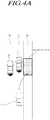
- FIGs. 4A and 4B illustrate examples in which a vehicle including the apparatus 200 for controlling collision avoidance avoids a forward collision according to embodiments of the present disclosure.
- FIG. 4A illustrates the case in which the risk of a collision with a first preceding vehicle 11, located ahead in a traveling lane 10 in which a host vehicle 1 travels, and a second preceding vehicle 12, located in a first adjacent lane 20 adjacent to the traveling lane 10, is detected.
- the host vehicle 1 since the host vehicle 1 includes the apparatus 200 for controlling collision avoidance, the host vehicle 1 may search for an avoidance area and set an avoidance path so as to prevent the forward collision. That is, a second adjacent lane 30, which is adjacent to the traveling lane 10 and in which no other vehicle is detected, is decided on as an optimal avoidance area in consideration of at least one piece of object information, space information, and road information around the host vehicle 1, and thus the host vehicle 1 may move to the avoidance area (the rectangular area illustrated in FIG. 4A ) in the second adjacent lane 30.
- the avoidance area the rectangular area illustrated in FIG. 4A
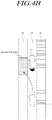
- FIG. 4B illustrates the case in which the risk of a forward collision with the preceding vehicle 11 located ahead in the traveling lane 10 in which the host vehicle 1 travels is detected.
- One of the two lanes 20 and 40 adjacent to the traveling lane 10 is detected as a roadway 20 and the other one is detected as a pedestrian walkway 40 in consideration of at least one piece of object information, space information, and road information around the host vehicle 1.
- the lane adjacent to the traveling lane 10 is referred to as a first adjacent lane 20 and the pedestrian walkway is referred to as a sidewalk 40.
- the host vehicle 1 may move to the avoidance area (the rectangular area illustrated in FIG. 4B ) in the first adjacent lane 20.
- FIGs. 5A to 5C illustrate other examples in which the vehicle including the apparatus 200 for controlling collision avoidance avoids the forward collision according to embodiments of the present disclosure.
- FIG. 5A illustrates the case in which the risk of a forward collision with a first preceding vehicle 11, located ahead in a traveling lane 10 in which the host vehicle 1 travels, is detected.
- the host vehicle 1 since the host vehicle 1 includes the apparatus 200 for controlling collision avoidance, the host vehicle 1 may search for an avoidance area and set an avoidance path so as to prevent a forward collision. That is, since no other vehicle is detected in the first adjacent lane 20 and the second adjacent lane 30, which are adjacent to the traveling lane 10, in consideration of at least one piece of object information, space information, and road information around the host vehicle 1, a first avoidance area and a second avoidance area may be selected as candidate areas, as illustrated in FIG. 5A .
- the reference score of the first avoidance area is set to be reduced, so that the second avoidance area located in the second adjacent lane 30 may be the optimal avoidance area. Accordingly, the host vehicle 1 may move to the second avoidance area in the second adjacent lane 30.
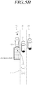
- FIG. 5B illustrates the case in which the risk of a forward collision with the first preceding vehicle 11, located ahead in the traveling lane 10 in which the host vehicle 1 travels, is detected, a second preceding vehicle 12 travels in the first adjacent lane 20, which is adjacent to the traveling lane 10, and a third preceding vehicle 13 travels in the second adjacent lane 30.
- the optimal avoidance area may be an avoidance area (a rectangular area illustrated in FIG. 5B ) located in the first adjacent lane 20.
- FIG. 5C illustrates the case in which the risk of a forward collision with the first preceding vehicle 11, located ahead in the traveling lane 10 in which the host vehicle 1 travels, is detected, wherein the second preceding vehicle 12 travels in the first adjacent lane 20, which is adjacent to the traveling lane 10, and the third preceding vehicle 13 travels in the second adjacent lane 30, but the driving speed of the second preceding vehicle 12 and the driving speed of the third preceding vehicle 13 are slow, so that the risk of a forward collision with the host vehicle 1 is detected.
- the speed of the host vehicle 1 may be reduced, the object information, the space information, and the road information around the host vehicle 1 may be detected in real time, and a candidate area may be immediately searched for again.
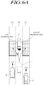
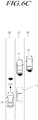
- FIGs. 6A to 6C illustrate other examples in which the vehicle including the apparatus 200 for controlling collision avoidance avoids a forward collision according to embodiments of the present disclosure.
- FIG. 6A illustrates the case in which the risk of forward collision with the first preceding vehicle 11, located ahead in the traveling lane 10 in which the host vehicle 1 travels, is detected.
- a fourth following vehicle 14 travels in the first adjacent lane 20, which is adjacent to the traveling lane 10, at a traveling speed u14, and a third following vehicle 13 travels in the second adjacent lane 30 at a traveling speed u13.
- the host vehicle 1 since the host vehicle 1 includes the apparatus 200 for controlling collision avoidance, the host 1 may search for an avoidance area and set an avoidance path so as to prevent a forward collision. That is, since spaces are detected in the first adjacent lane 20 and the second adjacent lane 30, which are adjacent to the traveling lane 10, in consideration of at least one piece of object information, space information, and road information around the host vehicle 1, a first avoidance area and a second avoidance area may be selected as candidate areas, as illustrated in FIG. 6A .
- the traveling speed u14 of the fourth following vehicle 14 traveling in the first adjacent lane 20 is fast enough to cause a rear-end collision with the host vehicle 1
- the reference score of the first avoidance area is set to be reduced, and the optimal avoidance area may be the second avoidance area, which is located in the second adjacent lane 30. Accordingly, the host vehicle 1 may move to the second avoidance area in the second adjacent lane 30.
- FIG. 6B illustrates the case in which the risk of a forward collision with the first preceding vehicle 11, located ahead in the traveling lane 10 in which the host vehicle 1 travels, is detected, wherein the fourth following vehicle 12 travels in the first adjacent lane 20, which is adjacent to the traveling lane 10 at a traveling speed u14 and the third preceding vehicle 13 travels in the second adjacent lane 30.
- the optimal avoidance area may be an avoidance area (a rectangular area illustrated in FIG. 6B ) located in the first adjacent lane 20.
- FIG. 6C illustrates a case which is the same as the case of FIG. 6B , but there is the risk of a forward collision between the host vehicle 1 and the third preceding vehicle 13 and the traveling speed u14 of the fourth following vehicle 14 is fast enough to generate a rear-end collision with the host vehicle 1.
- the speed of the host vehicle 1 may be reduced, the object information, the space information, and the road information around the host vehicle 1 may be detected in real time, and a candidate area may be immediately searched for again.
- FIG. 7 is a flowchart briefly illustrating a method of controlling collision avoidance according to embodiments of the present disclosure.
- a method of controlling collision avoidance may include: a warning signal reception step S600 of receiving an emergency braking warning signal for a forward collision of a host vehicle; a traveling environment detection step S610 of detecting object information, road information, and space information pertaining to areas in front of, to the side of, and in back of the host vehicle if the warning signal is received; an emergency braking determination step S620 of determining whether the risk of a forward collision of the host vehicle is larger than or equal to a first threshold value if the warning signal is received; an avoidance area determination step S630 of searching for drivable lanes of the host vehicle and one or more candidate areas in the space according to the determined risk of the forward collision, calculating a score of each of the candidate areas, determining an avoidance area, and setting an avoidance path for the avoidance area; and a control signal output step S640 of outputting steering and speed control signals for moving the host vehicle to the avoidance area along the avoidance path.
- an emergency braking warning signal may be received from the output unit 130 of the AEB system and the emergency braking warning signal may be a phased warning signal.
- the emergency braking warning signal may have a plurality of risk levels and, particularly, a two-step level.
- a traveling environment detection step S610 and an emergency braking determination step S620 may be performed.
- the warning signal is received in the warning signal reception step S600, at least one piece of object information, road information, and space information may be detected, or at least one piece of object information, road information, and space information may be received from the autonomous driving support integrated system within the host vehicle in the warning signal reception step S610.
- the object information, the road information, and the space information are information detected by the camera module 150, the non-image sensor module 160, and the intra-vehicle sensor module 190 illustrated in FIGS. 1 and 2 , information extracted by the detector 110 of FIG. 2 from data captured by the camera module 150, the non-image sensor module 160, and the intra-vehicle sensor module 190 illustrated in FIGs. 1 and 2 , or information directly extracted by the driving environment detector 210.
- the object information, the road information, and the space information in front of the vehicle may be detected by a camera and a radar mounted to the front of the host vehicle and radars mounted to both front-side surfaces
- the object information, the road information, and the space information in back of the vehicle may be detected by a camera mounted to the rear of the host vehicle and radars mounted to both rear-side surfaces.
- the forward collision risk may be calculated on the basis of information received from the AEB system. If the forward collision risk is higher than or equal to a first threshold value, it may be determined that the forward collision will occur if the host vehicle performs a full-braking operation.
- the forward collision risk may be calculated on the basis of a Time-To-Collision (TTC), which is a value generated by dividing a separation distance between the host vehicle and a preceding object, that is, another vehicle, by a relative speed.
- TTC Time-To-Collision
- drivable lanes and candidate areas may be searched for on the basis of at least one piece of the detected object information, road information, and space information in the avoidance area determination step S630.
- the candidate area is located behind or beside the host vehicle to make the vehicle avoid the forward collision, and the number of candidate areas may be one or more.
- the avoidance area may be selected from among the candidate areas.
- the score may be converted and calculated on the basis of information on the drivable lanes, information on objects located in front of or in back of the candidate areas, and space information of the candidate areas and the host vehicle.
- the object information used for calculating the scores may include at least one of the object type, the location, the speed, and the risk of collision with the host vehicle, information on the drivable way may include the type and location of the way adjacent to the traveling lane in which the host vehicle travels, and the candidate area and the space information of the host vehicle may include the lane width of the candidate area and the vehicle width of the host vehicle.
- the candidate area having the largest score may be determined as the avoidance area if the calculated score is larger than or equal to a second threshold value, and the drivable lanes and the candidate areas may be searched for again if the score is smaller than the second threshold value in the avoidance area determination step S630.
- the avoidance area determiner 240 may determine that the candidate area farthest from the centerline is the avoidance area.
- steering and speed control signals according to the avoidance path set in the avoidance area determination step S630 may be output, and may allow the host vehicle to move the avoidance area.
- FIG. 8 is a flowchart illustrating in detail the method of controlling collision avoidance according to embodiments of the present disclosure.
- the AEB system determines whether an emergency braking warning signal, output if the risk of the forward collision of the host vehicle is detected, is received in S710 in the warning signal reception step S600.
- the emergency braking warning signal may include a plurality of risk levels and, particularly, a two-step level.
- At least one piece of the object information, the road information, and the space information pertaining to the front, rear, and side of the host vehicle is detected in S720 in the traveling environment detection step S610.
- the risk of the forward collision may be calculated through the detected information in S730.
- the risk of the forward collision may be calculated on the basis of a Time-To-Collision (TTC), which is a value generated by dividing a separation distance between the host vehicle and a preceding object, that is, another vehicle, by a relative speed.
- TTC Time-To-Collision
- the first threshold value is a braking limit indicating the risk of the forward collision even though the host vehicle performs the full-braking operation. That is, if the collision risk is the braking limit, it may be determined that there is a very high collision possibility since the forward TTC of the host vehicle is short even though the host vehicle performs full braking.
- the traveling environment detection step S600 is continuously performed. That is, at least one piece of the object information, the road information, and the space information pertaining to the front, rear, and side of the host vehicle is detected in S720.
- the risk of the forward collision is larger than or equal to the first threshold value, it is determined whether there is a drivable lane among the traveling lane and adjacent lanes on the basis of the object information and the road information in S750 in the avoidance area determination step S630.
- the object information corresponds to a pedestrian or a vehicle and whether a road adjacent to the road on which the host vehicle travels is a sidewalk, a shoulder, or a roadway, so as to determine the drivable way that can be selected as the candidate area.
- candidate areas are searched for and selected in S760.
- the candidate areas may be searched for on the basis of at least one piece of the object information, the road information, and the space information.
- scores may be converted and calculated on the basis of information on the drivable way and information on objects located in front of and in back of the candidate area in S770.
- the object information used for calculating the scores may include at least one of the type of the object, the location, the speed, and the risk of collision with the host vehicle, and the information on the drivable way may include the type and the location of the way adjacent to the traveling lane in which the host vehicle travels.
- avoidance area determination step S630 it is determined whether the calculated score is larger than or equal to a second threshold value in S780.
- the score is smaller than the second threshold value, the drivable way and the avoidance area are searched for again in S750.
- the candidate area having the largest score is determined as the avoidance area in S790. Simultaneously with the determination of the avoidance area, an avoidance path along which the host vehicle moves to the avoidance area is set in S800.
- the host vehicle is moved by outputting steering and speed control signals to make the host vehicle move to the avoidance area along the avoidance path set in the control signal output step S640 in S810.
- the steering and speed control signals may be transmitted to at least one of the EPS, the brake, and the accelerator of the host vehicle.
- the apparatus and the method for controlling collision avoidance have an effect of providing safety of traveling, preventing a collision between vehicles, and improving accuracy of the avoidance path and the avoidance area by controlling a vehicle to avoid a collision with a preceding object.
Applications Claiming Priority (1)
| Application Number | Priority Date | Filing Date | Title |
|---|---|---|---|
| KR1020180027687A KR102553730B1 (ko) | 2018-03-08 | 2018-03-08 | 차량의 충돌 회피 제어 장치 및 방법 |
Publications (2)
| Publication Number | Publication Date |
|---|---|
| EP3536575A2 true EP3536575A2 (fr) | 2019-09-11 |
| EP3536575A3 EP3536575A3 (fr) | 2019-12-18 |
Family
ID=65443668
Family Applications (1)
| Application Number | Title | Priority Date | Filing Date |
|---|---|---|---|
| EP19156899.7A Pending EP3536575A3 (fr) | 2018-03-08 | 2019-02-13 | Appareil et procédé de commande d'évitement de collisions de véhicule |
Country Status (4)
| Country | Link |
|---|---|
| US (1) | US10688990B2 (fr) |
| EP (1) | EP3536575A3 (fr) |
| KR (1) | KR102553730B1 (fr) |
| CN (1) | CN110239531B (fr) |
Cited By (5)
| Publication number | Priority date | Publication date | Assignee | Title |
|---|---|---|---|---|
| EP3852083A1 (fr) * | 2020-01-14 | 2021-07-21 | Veoneer Sweden AB | Système et procédé de détection et d'évitement d'obstacles sur des routes |
| WO2022063464A1 (fr) * | 2020-09-22 | 2022-03-31 | Valeo Vision | Système d'aide à la conduite d'un véhicule |
| CN114312767A (zh) * | 2021-12-30 | 2022-04-12 | 盐城工学院 | 一种汽车的智能化主动避让控制系统 |
| EP4082851A1 (fr) * | 2021-04-28 | 2022-11-02 | KNORR-BREMSE Systeme für Nutzfahrzeuge GmbH | Appareil de prédiction d'une trajectoire prédite pour un système d'assistance au conducteur de sécurité d'un véhicule |
| EP4098501A1 (fr) * | 2021-06-03 | 2022-12-07 | Hyundai Motor Company | Système de mouvement latéral d'évitement de collision |
Families Citing this family (39)
| Publication number | Priority date | Publication date | Assignee | Title |
|---|---|---|---|---|
| JP6994567B2 (ja) * | 2018-05-15 | 2022-01-14 | 日立Astemo株式会社 | 車両制御装置 |
| JP7456442B2 (ja) * | 2019-06-14 | 2024-03-27 | ソニーグループ株式会社 | 情報処理装置、および情報処理方法、並びにプログラム |
| JP7121715B2 (ja) * | 2019-09-19 | 2022-08-18 | 本田技研工業株式会社 | 推定装置、推定方法、及びプログラム |
| KR102353121B1 (ko) * | 2019-09-20 | 2022-01-19 | 김응주 | 빅데이터 기술 기반 차량의 안전 운행 제어 시스템 및 그 방법 |
| KR20210042188A (ko) * | 2019-10-08 | 2021-04-19 | 현대자동차주식회사 | 차량 및 그 제어방법 |
| CN112824185B (zh) * | 2019-11-19 | 2022-05-03 | 广州汽车集团股份有限公司 | 一种碰撞预警方法、集成tbox的v2x控制器系统及汽车 |
| KR102304018B1 (ko) * | 2019-12-10 | 2021-09-23 | 주식회사 라이드플럭스 | 자율주행 차량의 충돌 방지 방법, 장치 및 컴퓨터프로그램 |
| US11279350B2 (en) * | 2019-12-27 | 2022-03-22 | Automotive Research & Testing Center | Method of adaptive trajectory generation for a vehicle |
| US11511576B2 (en) * | 2020-01-24 | 2022-11-29 | Ford Global Technologies, Llc | Remote trailer maneuver assist system |
| CN113386738A (zh) * | 2020-03-13 | 2021-09-14 | 奥迪股份公司 | 风险预警系统、方法和存储介质 |
| CN113408320A (zh) * | 2020-03-16 | 2021-09-17 | 上海博泰悦臻网络技术服务有限公司 | 用于车辆避撞的方法、电子设备和计算机存储介质 |
| KR20210124603A (ko) * | 2020-04-06 | 2021-10-15 | 현대자동차주식회사 | 차량의 자율 주행 제어 장치, 그를 포함한 시스템 및 그 방법 |
| US11491976B2 (en) * | 2020-04-21 | 2022-11-08 | Baidu Usa Llc | Collision warning system for safety operators of autonomous vehicles |
| JP2021189653A (ja) * | 2020-05-28 | 2021-12-13 | 現代自動車株式会社Hyundai Motor Company | 自動運転車両のクラスタ群形成による走行制御方法 |
| KR20210150922A (ko) * | 2020-06-04 | 2021-12-13 | 현대모비스 주식회사 | 차량의 주행 제어 시스템 및 방법 |
| KR20210150921A (ko) * | 2020-06-04 | 2021-12-13 | 현대모비스 주식회사 | 차량의 안전 주행 제어 시스템 및 방법 |
| KR20210156906A (ko) * | 2020-06-18 | 2021-12-28 | 현대모비스 주식회사 | 차량의 사각지대 회피 시스템 및 방법 |
| CN113873426A (zh) * | 2020-06-30 | 2021-12-31 | 罗伯特·博世有限公司 | 用于决策车辆的地理围栏事件的系统、控制单元和方法 |
| CN112099485A (zh) * | 2020-08-03 | 2020-12-18 | 深圳市优必选科技股份有限公司 | 危险区域规避方法、装置、计算机可读存储介质及机器人 |
| US11787440B2 (en) * | 2020-08-04 | 2023-10-17 | Baidu Usa Llc | Lane boundary and vehicle speed based nudge decision |
| KR20220026005A (ko) * | 2020-08-24 | 2022-03-04 | 현대모비스 주식회사 | 레이더 센서를 기반으로 한 차선 변경 충돌 예측 시스템 및 방법 |
| US11814075B2 (en) * | 2020-08-26 | 2023-11-14 | Motional Ad Llc | Conditional motion predictions |
| CN112109707B (zh) * | 2020-09-07 | 2022-01-07 | 东风汽车集团有限公司 | 一种针对vru的紧急车道保持辅助方法 |
| KR20220049630A (ko) * | 2020-10-14 | 2022-04-22 | 현대자동차주식회사 | 자동차 및 그를 위한 제어 방법 |
| CN112270090A (zh) * | 2020-10-26 | 2021-01-26 | 华电重工股份有限公司 | 一种吊索选择方法、装置、电子设备及存储介质 |
| CN112550243A (zh) * | 2020-12-18 | 2021-03-26 | 月峰 | 一种新能源汽车的防撞保护装置 |
| DE112021006993T5 (de) * | 2021-02-04 | 2023-11-30 | Honda Motor Co., Ltd. | Fahrzeug vom spreitzsitztyp, verfahren zum steuern davon, steuerungsvorrichtung und programm |
| KR20220131426A (ko) * | 2021-03-18 | 2022-09-28 | 현대모비스 주식회사 | 차량 제어 시스템 및 방법 |
| CN115214632A (zh) * | 2021-03-31 | 2022-10-21 | 南宁富联富桂精密工业有限公司 | 车辆盲区的防碰撞方法、电子设备及计算机存储介质 |
| CN113232650A (zh) * | 2021-05-31 | 2021-08-10 | 吉林大学 | 一种面对有前方车辆汇入的车辆避撞控制系统及控制方法 |
| CN113212459A (zh) * | 2021-06-17 | 2021-08-06 | 鄂尔多斯市普渡科技有限公司 | 一种可自动排障的自动驾驶车辆检测系统及方法 |
| US20230030815A1 (en) * | 2021-07-29 | 2023-02-02 | Argo AI, LLC | Complementary control system for an autonomous vehicle |
| US11639181B2 (en) * | 2021-09-29 | 2023-05-02 | Nissan North America, Inc. | Lead vehicle braking warning system |
| CN113923624B (zh) * | 2021-10-29 | 2023-11-17 | 东风越野车有限公司 | 一种基于ZigBee的车联网通信方法及系统 |
| US11541910B1 (en) * | 2022-01-07 | 2023-01-03 | Plusai, Inc. | Methods and apparatus for navigation of an autonomous vehicle based on a location of the autonomous vehicle relative to shouldered objects |
| CN114347041B (zh) * | 2022-02-21 | 2024-03-08 | 汕头市快畅机器人科技有限公司 | 群体机器人控制与图案生成方法 |
| US11840257B2 (en) * | 2022-03-25 | 2023-12-12 | Embark Trucks Inc. | Lane change determination for vehicle on shoulder |
| CN114724366B (zh) * | 2022-03-29 | 2023-06-20 | 北京万集科技股份有限公司 | 辅助驾驶方法、装置、设备和存储介质 |
| WO2024064621A1 (fr) * | 2022-09-19 | 2024-03-28 | Velios Inc. | Systèmes et procédés de conscience de la situation et plateforme de micromobilité |
Family Cites Families (32)
| Publication number | Priority date | Publication date | Assignee | Title |
|---|---|---|---|---|
| JP2748287B2 (ja) | 1992-02-28 | 1998-05-06 | 三菱自動車工業株式会社 | 4輪操舵装置 |
| DE10036276A1 (de) | 2000-07-26 | 2002-02-07 | Daimler Chrysler Ag | Automatisches Brems- und Lenksystem für ein Fahrzeug |
| CN1799909A (zh) * | 2005-01-02 | 2006-07-12 | 傅建中 | 被动式汽车追尾预警避撞技术方案 |
| JP4949063B2 (ja) * | 2007-02-14 | 2012-06-06 | 富士重工業株式会社 | 車両の運転支援装置 |
| EP2060455B1 (fr) * | 2007-11-16 | 2012-08-08 | Aisin AW Co., Ltd. | Dispositif de contrôle de véhicule, procédé de contrôle de véhicule, et programme informatique |
| JP2009151648A (ja) * | 2007-12-21 | 2009-07-09 | Mitsubishi Fuso Truck & Bus Corp | 車両用警報装置 |
| AT507035B1 (de) * | 2008-07-15 | 2020-07-15 | Airbus Defence & Space Gmbh | System und verfahren zur kollisionsvermeidung |
| JP5210233B2 (ja) * | 2009-04-14 | 2013-06-12 | 日立オートモティブシステムズ株式会社 | 車両用外界認識装置及びそれを用いた車両システム |
| US20120083983A1 (en) * | 2009-06-19 | 2012-04-05 | Bosch Corporation | Vehicular braking control device |
| JP5278378B2 (ja) * | 2009-07-30 | 2013-09-04 | 日産自動車株式会社 | 車両運転支援装置及び車両運転支援方法 |
| JP5464333B2 (ja) * | 2009-09-18 | 2014-04-09 | ダイムラー・アクチェンゲゼルシャフト | 前面衝突時オーバーラップ量制御装置 |
| JP6336758B2 (ja) | 2011-03-04 | 2018-06-06 | コンティネンタル・テーベス・アクチエンゲゼルシヤフト・ウント・コンパニー・オッフェネ・ハンデルスゲゼルシヤフト | 回避アシスタントの作動の制限 |
| WO2013051083A1 (fr) * | 2011-10-03 | 2013-04-11 | トヨタ自動車株式会社 | Système d'assistance à la conduite de véhicule |
| KR101361360B1 (ko) * | 2011-12-26 | 2014-02-11 | 현대자동차주식회사 | 측후방 감지센서를 이용한 차간거리 제어 시스템 및 그 제어 방법 |
| JP5780249B2 (ja) * | 2012-02-27 | 2015-09-16 | 株式会社デンソー | 画像処理装置及び、当該画像処理装置を用いた車両制御システム |
| JP5785515B2 (ja) * | 2012-04-04 | 2015-09-30 | 株式会社デンソーアイティーラボラトリ | 歩行者検出装置及び方法、並びに車両用衝突判定装置 |
| US9000903B2 (en) * | 2012-07-09 | 2015-04-07 | Elwha Llc | Systems and methods for vehicle monitoring |
| KR20140126975A (ko) * | 2013-04-24 | 2014-11-03 | 주식회사 만도 | 차량의 충돌 회피 장치 및 방법 |
| JP5783430B2 (ja) * | 2013-04-26 | 2015-09-24 | 株式会社デンソー | 衝突緩和装置 |
| DE102014206338A1 (de) | 2014-04-02 | 2015-10-08 | Bayerische Motoren Werke Aktiengesellschaft | Ausweichassistent |
| JP6627093B2 (ja) * | 2014-06-30 | 2020-01-08 | 本田技研工業株式会社 | 車両制御装置、車両制御方法、及び、車両制御用プログラム |
| KR101610544B1 (ko) * | 2014-11-21 | 2016-04-07 | 현대자동차주식회사 | 차량의 자율 주행 시스템 및 방법 |
| EP3095659A1 (fr) * | 2015-05-19 | 2016-11-23 | Volvo Car Corporation | Procédé et système pour fournir une manoeuvre d'évitement adaptée au comportement d'un conducteur |
| US9751506B2 (en) * | 2015-10-27 | 2017-09-05 | GM Global Technology Operations LLC | Algorithms for avoiding automotive crashes at left and right turn intersections |
| KR102187463B1 (ko) * | 2015-12-08 | 2020-12-07 | 현대자동차 주식회사 | 차량 긴급회피보조 시스템 및 그 방법 |
| KR20170068062A (ko) | 2015-12-09 | 2017-06-19 | 현대자동차주식회사 | 차량의 후방추돌 회피장치 및 방법 |
| JP2017117191A (ja) * | 2015-12-24 | 2017-06-29 | 三菱自動車工業株式会社 | 運転支援装置 |
| JP6330825B2 (ja) * | 2016-01-26 | 2018-05-30 | トヨタ自動車株式会社 | 車両用衝突回避支援システム |
| US9896096B2 (en) * | 2016-04-11 | 2018-02-20 | David E. Newman | Systems and methods for hazard mitigation |
| CN106157696B (zh) * | 2016-08-30 | 2019-03-29 | 浙江吉利控股集团有限公司 | 基于车-车通信的自车主动避让系统和避让方法 |
| US10262538B1 (en) * | 2016-09-22 | 2019-04-16 | Apple Inc. | Database management for potential pull-off areas |
| CN106816036A (zh) * | 2017-04-01 | 2017-06-09 | 北京中鼎思宏科技有限公司 | 车辆碰撞风险的预警方法及系统 |
-
2018
- 2018-03-08 KR KR1020180027687A patent/KR102553730B1/ko active IP Right Grant
- 2018-12-11 US US16/216,912 patent/US10688990B2/en active Active
-
2019
- 2019-01-21 CN CN201910052464.XA patent/CN110239531B/zh active Active
- 2019-02-13 EP EP19156899.7A patent/EP3536575A3/fr active Pending
Non-Patent Citations (1)
| Title |
|---|
| None |
Cited By (5)
| Publication number | Priority date | Publication date | Assignee | Title |
|---|---|---|---|---|
| EP3852083A1 (fr) * | 2020-01-14 | 2021-07-21 | Veoneer Sweden AB | Système et procédé de détection et d'évitement d'obstacles sur des routes |
| WO2022063464A1 (fr) * | 2020-09-22 | 2022-03-31 | Valeo Vision | Système d'aide à la conduite d'un véhicule |
| EP4082851A1 (fr) * | 2021-04-28 | 2022-11-02 | KNORR-BREMSE Systeme für Nutzfahrzeuge GmbH | Appareil de prédiction d'une trajectoire prédite pour un système d'assistance au conducteur de sécurité d'un véhicule |
| EP4098501A1 (fr) * | 2021-06-03 | 2022-12-07 | Hyundai Motor Company | Système de mouvement latéral d'évitement de collision |
| CN114312767A (zh) * | 2021-12-30 | 2022-04-12 | 盐城工学院 | 一种汽车的智能化主动避让控制系统 |
Also Published As
| Publication number | Publication date |
|---|---|
| US20190276013A1 (en) | 2019-09-12 |
| US10688990B2 (en) | 2020-06-23 |
| KR102553730B1 (ko) | 2023-07-11 |
| EP3536575A3 (fr) | 2019-12-18 |
| CN110239531B (zh) | 2022-06-10 |
| CN110239531A (zh) | 2019-09-17 |
| KR20190106339A (ko) | 2019-09-18 |
Similar Documents
| Publication | Publication Date | Title |
|---|---|---|
| US10688990B2 (en) | Apparatus and method for controlling collision avoidance of vehicle | |
| US11027653B2 (en) | Apparatus, system and method for preventing collision | |
| US11208085B2 (en) | Automotive braking control system, apparatus, and method considering weather condition | |
| US11318939B2 (en) | Apparatus and a method for controlling an inter-vehicle distance | |
| US11214244B2 (en) | Vehicle collision avoidance control device and method for controlling same | |
| US11021172B2 (en) | System for controlling host vehicle and method for controlling host vehicle | |
| US10775799B2 (en) | Autonomous cruise control apparatus and method | |
| KR102637599B1 (ko) | 차량간 통신 정보를 이용한 차선변경 제어장치 및 방법과, 그를 위한 성향 정보 산출 장치 | |
| US10800432B2 (en) | Rear-side alert system and method of controlling same | |
| US11897458B2 (en) | Collision avoidance apparatus for vehicle | |
| US11531108B2 (en) | Apparatus and method for detecting target | |
| CN111086507B (zh) | 用于避免下一车道车辆的盲点的装置及方法 | |
| US20190329744A1 (en) | Alert and control system and method for assisting driver | |
| US11325588B2 (en) | Vehicle control system and vehicle control method | |
| US11567192B2 (en) | Radar for vehicle | |
| CN111483457B (zh) | 用于避免碰撞的装置、系统和方法 | |
| US20230234570A1 (en) | Driver assistance apparatus and driver assistance method | |
| WO2022239348A1 (fr) | Dispositif radar, procédé de traitement de signal, et programme | |
| CN109991596B (zh) | 用于检测目标的设备和方法 | |
| WO2023021756A1 (fr) | Système de traitement d'informations, dispositif de traitement d'informations et procédé de traitement d'informations | |
| CN114690183A (zh) | 基于多个模式检测对象的雷达装置及方法 |
Legal Events
| Date | Code | Title | Description |
|---|---|---|---|
| PUAI | Public reference made under article 153(3) epc to a published international application that has entered the european phase |
Free format text: ORIGINAL CODE: 0009012 |
|
| STAA | Information on the status of an ep patent application or granted ep patent |
Free format text: STATUS: REQUEST FOR EXAMINATION WAS MADE |
|
| 17P | Request for examination filed |
Effective date: 20190213 |
|
| AK | Designated contracting states |
Kind code of ref document: A2 Designated state(s): AL AT BE BG CH CY CZ DE DK EE ES FI FR GB GR HR HU IE IS IT LI LT LU LV MC MK MT NL NO PL PT RO RS SE SI SK SM TR |
|
| AX | Request for extension of the european patent |
Extension state: BA ME |
|
| PUAL | Search report despatched |
Free format text: ORIGINAL CODE: 0009013 |
|
| AK | Designated contracting states |
Kind code of ref document: A3 Designated state(s): AL AT BE BG CH CY CZ DE DK EE ES FI FR GB GR HR HU IE IS IT LI LT LU LV MC MK MT NL NO PL PT RO RS SE SI SK SM TR |
|
| AX | Request for extension of the european patent |
Extension state: BA ME |
|
| RIC1 | Information provided on ipc code assigned before grant |
Ipc: G05D 1/02 20060101ALI20191113BHEP Ipc: B60W 30/08 20120101ALI20191113BHEP Ipc: B60W 30/095 20120101ALI20191113BHEP Ipc: B60W 30/12 20060101ALI20191113BHEP Ipc: B60W 30/085 20120101ALI20191113BHEP Ipc: B60W 50/00 20060101AFI20191113BHEP |
|
| RBV | Designated contracting states (corrected) |
Designated state(s): AL AT BE BG CH CY CZ DE DK EE ES FI FR GB GR HR HU IE IS IT LI LT LU LV MC MK MT NL NO PL PT RO RS SE SI SK SM TR |
|
| STAA | Information on the status of an ep patent application or granted ep patent |
Free format text: STATUS: EXAMINATION IS IN PROGRESS |
|
| 17Q | First examination report despatched |
Effective date: 20220121 |
|
| RAP1 | Party data changed (applicant data changed or rights of an application transferred) |
Owner name: MANDO MOBILITY SOLUTIONS CORPORATION |
|
| RAP1 | Party data changed (applicant data changed or rights of an application transferred) |
Owner name: HL KLEMOVE CORP. |
|
| GRAP | Despatch of communication of intention to grant a patent |
Free format text: ORIGINAL CODE: EPIDOSNIGR1 |
|
| STAA | Information on the status of an ep patent application or granted ep patent |
Free format text: STATUS: GRANT OF PATENT IS INTENDED |
|
| RIC1 | Information provided on ipc code assigned before grant |
Ipc: B60W 30/08 20120101ALI20240325BHEP Ipc: B60W 30/085 20120101ALI20240325BHEP Ipc: B60W 30/095 20120101ALI20240325BHEP Ipc: B60W 30/12 20060101ALI20240325BHEP Ipc: B60W 50/00 20060101AFI20240325BHEP |