EP3534838B1 - Système de pose d'endoprothèse à ajustement radial - Google Patents
Système de pose d'endoprothèse à ajustement radial Download PDFInfo
- Publication number
- EP3534838B1 EP3534838B1 EP18709883.5A EP18709883A EP3534838B1 EP 3534838 B1 EP3534838 B1 EP 3534838B1 EP 18709883 A EP18709883 A EP 18709883A EP 3534838 B1 EP3534838 B1 EP 3534838B1
- Authority
- EP
- European Patent Office
- Prior art keywords
- ligature
- stent
- control rod
- stent graft
- luminal
- Prior art date
- Legal status (The legal status is an assumption and is not a legal conclusion. Google has not performed a legal analysis and makes no representation as to the accuracy of the status listed.)
- Active
Links
- 230000002441 reversible effect Effects 0.000 claims 1
- 206010002329 Aneurysm Diseases 0.000 description 18
- 238000000034 method Methods 0.000 description 15
- 230000007704 transition Effects 0.000 description 9
- 208000007474 aortic aneurysm Diseases 0.000 description 6
- 230000002792 vascular Effects 0.000 description 6
- 208000001750 Endoleak Diseases 0.000 description 2
- 210000000709 aorta Anatomy 0.000 description 2
- 210000004204 blood vessel Anatomy 0.000 description 2
- 239000000463 material Substances 0.000 description 2
- 229910001000 nickel titanium Inorganic materials 0.000 description 2
- HLXZNVUGXRDIFK-UHFFFAOYSA-N nickel titanium Chemical compound [Ti].[Ti].[Ti].[Ti].[Ti].[Ti].[Ti].[Ti].[Ti].[Ti].[Ti].[Ni].[Ni].[Ni].[Ni].[Ni].[Ni].[Ni].[Ni].[Ni].[Ni].[Ni].[Ni].[Ni].[Ni] HLXZNVUGXRDIFK-UHFFFAOYSA-N 0.000 description 2
- 230000007170 pathology Effects 0.000 description 2
- 229910001285 shape-memory alloy Inorganic materials 0.000 description 2
- 230000003966 vascular damage Effects 0.000 description 2
- 206010061307 Neck deformity Diseases 0.000 description 1
- 239000004677 Nylon Substances 0.000 description 1
- 239000004743 Polypropylene Substances 0.000 description 1
- 208000027418 Wounds and injury Diseases 0.000 description 1
- 208000002223 abdominal aortic aneurysm Diseases 0.000 description 1
- 210000003484 anatomy Anatomy 0.000 description 1
- 238000004873 anchoring Methods 0.000 description 1
- 210000004369 blood Anatomy 0.000 description 1
- 239000008280 blood Substances 0.000 description 1
- 230000017531 blood circulation Effects 0.000 description 1
- 210000002302 brachial artery Anatomy 0.000 description 1
- 230000006378 damage Effects 0.000 description 1
- 230000003247 decreasing effect Effects 0.000 description 1
- 230000007717 exclusion Effects 0.000 description 1
- 239000007943 implant Substances 0.000 description 1
- 238000002513 implantation Methods 0.000 description 1
- 208000014674 injury Diseases 0.000 description 1
- 238000004519 manufacturing process Methods 0.000 description 1
- 229920001778 nylon Polymers 0.000 description 1
- 210000000056 organ Anatomy 0.000 description 1
- 210000005259 peripheral blood Anatomy 0.000 description 1
- 239000011886 peripheral blood Substances 0.000 description 1
- 229920000728 polyester Polymers 0.000 description 1
- 229920000642 polymer Polymers 0.000 description 1
- -1 polypropylene Polymers 0.000 description 1
- 229920001155 polypropylene Polymers 0.000 description 1
- 230000002040 relaxant effect Effects 0.000 description 1
- 239000010935 stainless steel Substances 0.000 description 1
- 229910001220 stainless steel Inorganic materials 0.000 description 1
- 210000005166 vasculature Anatomy 0.000 description 1
- 210000001835 viscera Anatomy 0.000 description 1
Images


Classifications
-
- A—HUMAN NECESSITIES
- A61—MEDICAL OR VETERINARY SCIENCE; HYGIENE
- A61F—FILTERS IMPLANTABLE INTO BLOOD VESSELS; PROSTHESES; DEVICES PROVIDING PATENCY TO, OR PREVENTING COLLAPSING OF, TUBULAR STRUCTURES OF THE BODY, e.g. STENTS; ORTHOPAEDIC, NURSING OR CONTRACEPTIVE DEVICES; FOMENTATION; TREATMENT OR PROTECTION OF EYES OR EARS; BANDAGES, DRESSINGS OR ABSORBENT PADS; FIRST-AID KITS
- A61F2/00—Filters implantable into blood vessels; Prostheses, i.e. artificial substitutes or replacements for parts of the body; Appliances for connecting them with the body; Devices providing patency to, or preventing collapsing of, tubular structures of the body, e.g. stents
- A61F2/95—Instruments specially adapted for placement or removal of stents or stent-grafts
-
- A—HUMAN NECESSITIES
- A61—MEDICAL OR VETERINARY SCIENCE; HYGIENE
- A61F—FILTERS IMPLANTABLE INTO BLOOD VESSELS; PROSTHESES; DEVICES PROVIDING PATENCY TO, OR PREVENTING COLLAPSING OF, TUBULAR STRUCTURES OF THE BODY, e.g. STENTS; ORTHOPAEDIC, NURSING OR CONTRACEPTIVE DEVICES; FOMENTATION; TREATMENT OR PROTECTION OF EYES OR EARS; BANDAGES, DRESSINGS OR ABSORBENT PADS; FIRST-AID KITS
- A61F2/00—Filters implantable into blood vessels; Prostheses, i.e. artificial substitutes or replacements for parts of the body; Appliances for connecting them with the body; Devices providing patency to, or preventing collapsing of, tubular structures of the body, e.g. stents
- A61F2/02—Prostheses implantable into the body
- A61F2/04—Hollow or tubular parts of organs, e.g. bladders, tracheae, bronchi or bile ducts
- A61F2/06—Blood vessels
- A61F2/07—Stent-grafts
-
- A—HUMAN NECESSITIES
- A61—MEDICAL OR VETERINARY SCIENCE; HYGIENE
- A61M—DEVICES FOR INTRODUCING MEDIA INTO, OR ONTO, THE BODY; DEVICES FOR TRANSDUCING BODY MEDIA OR FOR TAKING MEDIA FROM THE BODY; DEVICES FOR PRODUCING OR ENDING SLEEP OR STUPOR
- A61M25/00—Catheters; Hollow probes
- A61M25/01—Introducing, guiding, advancing, emplacing or holding catheters
- A61M25/09—Guide wires
-
- A—HUMAN NECESSITIES
- A61—MEDICAL OR VETERINARY SCIENCE; HYGIENE
- A61F—FILTERS IMPLANTABLE INTO BLOOD VESSELS; PROSTHESES; DEVICES PROVIDING PATENCY TO, OR PREVENTING COLLAPSING OF, TUBULAR STRUCTURES OF THE BODY, e.g. STENTS; ORTHOPAEDIC, NURSING OR CONTRACEPTIVE DEVICES; FOMENTATION; TREATMENT OR PROTECTION OF EYES OR EARS; BANDAGES, DRESSINGS OR ABSORBENT PADS; FIRST-AID KITS
- A61F2/00—Filters implantable into blood vessels; Prostheses, i.e. artificial substitutes or replacements for parts of the body; Appliances for connecting them with the body; Devices providing patency to, or preventing collapsing of, tubular structures of the body, e.g. stents
- A61F2/82—Devices providing patency to, or preventing collapsing of, tubular structures of the body, e.g. stents
- A61F2/86—Stents in a form characterised by the wire-like elements; Stents in the form characterised by a net-like or mesh-like structure
- A61F2/90—Stents in a form characterised by the wire-like elements; Stents in the form characterised by a net-like or mesh-like structure characterised by a net-like or mesh-like structure
-
- A—HUMAN NECESSITIES
- A61—MEDICAL OR VETERINARY SCIENCE; HYGIENE
- A61F—FILTERS IMPLANTABLE INTO BLOOD VESSELS; PROSTHESES; DEVICES PROVIDING PATENCY TO, OR PREVENTING COLLAPSING OF, TUBULAR STRUCTURES OF THE BODY, e.g. STENTS; ORTHOPAEDIC, NURSING OR CONTRACEPTIVE DEVICES; FOMENTATION; TREATMENT OR PROTECTION OF EYES OR EARS; BANDAGES, DRESSINGS OR ABSORBENT PADS; FIRST-AID KITS
- A61F2/00—Filters implantable into blood vessels; Prostheses, i.e. artificial substitutes or replacements for parts of the body; Appliances for connecting them with the body; Devices providing patency to, or preventing collapsing of, tubular structures of the body, e.g. stents
- A61F2/95—Instruments specially adapted for placement or removal of stents or stent-grafts
- A61F2/9517—Instruments specially adapted for placement or removal of stents or stent-grafts handle assemblies therefor
-
- A—HUMAN NECESSITIES
- A61—MEDICAL OR VETERINARY SCIENCE; HYGIENE
- A61F—FILTERS IMPLANTABLE INTO BLOOD VESSELS; PROSTHESES; DEVICES PROVIDING PATENCY TO, OR PREVENTING COLLAPSING OF, TUBULAR STRUCTURES OF THE BODY, e.g. STENTS; ORTHOPAEDIC, NURSING OR CONTRACEPTIVE DEVICES; FOMENTATION; TREATMENT OR PROTECTION OF EYES OR EARS; BANDAGES, DRESSINGS OR ABSORBENT PADS; FIRST-AID KITS
- A61F2/00—Filters implantable into blood vessels; Prostheses, i.e. artificial substitutes or replacements for parts of the body; Appliances for connecting them with the body; Devices providing patency to, or preventing collapsing of, tubular structures of the body, e.g. stents
- A61F2/95—Instruments specially adapted for placement or removal of stents or stent-grafts
- A61F2/9522—Means for mounting a stent or stent-graft onto or into a placement instrument
-
- A—HUMAN NECESSITIES
- A61—MEDICAL OR VETERINARY SCIENCE; HYGIENE
- A61F—FILTERS IMPLANTABLE INTO BLOOD VESSELS; PROSTHESES; DEVICES PROVIDING PATENCY TO, OR PREVENTING COLLAPSING OF, TUBULAR STRUCTURES OF THE BODY, e.g. STENTS; ORTHOPAEDIC, NURSING OR CONTRACEPTIVE DEVICES; FOMENTATION; TREATMENT OR PROTECTION OF EYES OR EARS; BANDAGES, DRESSINGS OR ABSORBENT PADS; FIRST-AID KITS
- A61F2/00—Filters implantable into blood vessels; Prostheses, i.e. artificial substitutes or replacements for parts of the body; Appliances for connecting them with the body; Devices providing patency to, or preventing collapsing of, tubular structures of the body, e.g. stents
- A61F2/02—Prostheses implantable into the body
- A61F2/04—Hollow or tubular parts of organs, e.g. bladders, tracheae, bronchi or bile ducts
- A61F2/06—Blood vessels
- A61F2/07—Stent-grafts
- A61F2002/075—Stent-grafts the stent being loosely attached to the graft material, e.g. by stitching
-
- A—HUMAN NECESSITIES
- A61—MEDICAL OR VETERINARY SCIENCE; HYGIENE
- A61F—FILTERS IMPLANTABLE INTO BLOOD VESSELS; PROSTHESES; DEVICES PROVIDING PATENCY TO, OR PREVENTING COLLAPSING OF, TUBULAR STRUCTURES OF THE BODY, e.g. STENTS; ORTHOPAEDIC, NURSING OR CONTRACEPTIVE DEVICES; FOMENTATION; TREATMENT OR PROTECTION OF EYES OR EARS; BANDAGES, DRESSINGS OR ABSORBENT PADS; FIRST-AID KITS
- A61F2/00—Filters implantable into blood vessels; Prostheses, i.e. artificial substitutes or replacements for parts of the body; Appliances for connecting them with the body; Devices providing patency to, or preventing collapsing of, tubular structures of the body, e.g. stents
- A61F2/82—Devices providing patency to, or preventing collapsing of, tubular structures of the body, e.g. stents
- A61F2002/826—Devices providing patency to, or preventing collapsing of, tubular structures of the body, e.g. stents more than one stent being applied sequentially
-
- A—HUMAN NECESSITIES
- A61—MEDICAL OR VETERINARY SCIENCE; HYGIENE
- A61F—FILTERS IMPLANTABLE INTO BLOOD VESSELS; PROSTHESES; DEVICES PROVIDING PATENCY TO, OR PREVENTING COLLAPSING OF, TUBULAR STRUCTURES OF THE BODY, e.g. STENTS; ORTHOPAEDIC, NURSING OR CONTRACEPTIVE DEVICES; FOMENTATION; TREATMENT OR PROTECTION OF EYES OR EARS; BANDAGES, DRESSINGS OR ABSORBENT PADS; FIRST-AID KITS
- A61F2/00—Filters implantable into blood vessels; Prostheses, i.e. artificial substitutes or replacements for parts of the body; Appliances for connecting them with the body; Devices providing patency to, or preventing collapsing of, tubular structures of the body, e.g. stents
- A61F2/95—Instruments specially adapted for placement or removal of stents or stent-grafts
- A61F2002/9505—Instruments specially adapted for placement or removal of stents or stent-grafts having retaining means other than an outer sleeve, e.g. male-female connector between stent and instrument
- A61F2002/9511—Instruments specially adapted for placement or removal of stents or stent-grafts having retaining means other than an outer sleeve, e.g. male-female connector between stent and instrument the retaining means being filaments or wires
-
- A—HUMAN NECESSITIES
- A61—MEDICAL OR VETERINARY SCIENCE; HYGIENE
- A61F—FILTERS IMPLANTABLE INTO BLOOD VESSELS; PROSTHESES; DEVICES PROVIDING PATENCY TO, OR PREVENTING COLLAPSING OF, TUBULAR STRUCTURES OF THE BODY, e.g. STENTS; ORTHOPAEDIC, NURSING OR CONTRACEPTIVE DEVICES; FOMENTATION; TREATMENT OR PROTECTION OF EYES OR EARS; BANDAGES, DRESSINGS OR ABSORBENT PADS; FIRST-AID KITS
- A61F2210/00—Particular material properties of prostheses classified in groups A61F2/00 - A61F2/26 or A61F2/82 or A61F9/00 or A61F11/00 or subgroups thereof
- A61F2210/0014—Particular material properties of prostheses classified in groups A61F2/00 - A61F2/26 or A61F2/82 or A61F9/00 or A61F11/00 or subgroups thereof using shape memory or superelastic materials, e.g. nitinol
-
- A—HUMAN NECESSITIES
- A61—MEDICAL OR VETERINARY SCIENCE; HYGIENE
- A61M—DEVICES FOR INTRODUCING MEDIA INTO, OR ONTO, THE BODY; DEVICES FOR TRANSDUCING BODY MEDIA OR FOR TAKING MEDIA FROM THE BODY; DEVICES FOR PRODUCING OR ENDING SLEEP OR STUPOR
- A61M25/00—Catheters; Hollow probes
- A61M25/01—Introducing, guiding, advancing, emplacing or holding catheters
- A61M25/09—Guide wires
- A61M2025/09008—Guide wires having a balloon
-
- A—HUMAN NECESSITIES
- A61—MEDICAL OR VETERINARY SCIENCE; HYGIENE
- A61M—DEVICES FOR INTRODUCING MEDIA INTO, OR ONTO, THE BODY; DEVICES FOR TRANSDUCING BODY MEDIA OR FOR TAKING MEDIA FROM THE BODY; DEVICES FOR PRODUCING OR ENDING SLEEP OR STUPOR
- A61M25/00—Catheters; Hollow probes
- A61M25/10—Balloon catheters
Definitions
- Arterial pathologies including aortic aneurysms, can be treated by open surgical reconstruction, or alternatively, endovascular repair, which is a minimally invasive alternative to open surgical repair.
- endovascular repair which is a minimally invasive alternative to open surgical repair.
- Optimizing a successful outcome of endovascular repair requires assessment of the patient's anatomy and, in the case of an aortic aneurysm, selection of an appropriate stent graft that spans the proximal and distal ends of the aneurysm to insure complete exclusion of the aneurysm sac, anchoring of the stent graft in the aorta, and minimal endoleaks.
- EP 2735283 A1 relates to an assembly of stent grafts with diameter reducing ties.
- US 2002/188344 A1 relates to a retrievable stent and method of use thereof.
- the present invention relates to a stent graft delivery system, as disclosed in claim 1.
- the physician can rotate or reposition the stent graft after it has been at least partially radially expanded, such as by only partially relaxing or reconstructing or reconstraining a ligature extending about stents of the stent graft by rotational movement of a control rod in which the ligature is wrapped.
- Axial or longitudinal repositioning of the reconstrained stent graft, or a portion thereof provides greater control over delivery systems that are only able to position the stent graft prior to full expansion of the stent graft within a blood vessel.
- a stent graft can be deployed at a surgical site with more accuracy, less risk of injury to the vasculature of the subject, and without significant risk of distorting the intended shape of the stent graft when implanted at the surgical site.
- the invention is generally directed to a stent graft delivery system that includes at least one control rod and at least one ligature that is releasably fixed to the control rod and about a stent of a stent graft.
- the stent graft delivery system and method are used to treat aortic vascular damage, such as vascular damage associated with an aortic aneurysms, including in regions of the aorta having arterial branches that supply blood to vital organs and tissues, such as juxtarenal aortic aneurysms and short-neck abdominal aortic aneurysms.
- proximal means that portion of the prosthesis or component of the prosthesis that is relatively close to the heart of the patient and “distal” means that portion of the prosthesis or component of the prosthesis that is relatively far from the heart of the patient.
- proximal means closer to the clinician using the delivery system.
- distal means, further away from the clinician using the delivery system.
- proximate means “close to,” as opposed to the meanings ascribed to “proximal” or “distal” described above with respect to either the prosthesis or a delivery system.
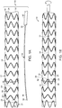
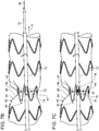
- stent graft delivery system 10 includes stent graft 12.
- Stent graft 12 includes luminal graft component 14 having outside surface 16, inside surface 18, proximal open end 20, distal open end 22, and defines lumen 24.
- a plurality of radial stents 26 extend longitudinally along luminal graft component 14.
- Stents 26 include struts 28 that are joined at opposite ends to thereby define proximal apices 30 and distal apices 32.
- Bare stent 21 is at proximal open end 20 and includes proximal apices 23 and distal apices 25.
- proximal apices 23 and distal apices 32 include barbs extending distally from bridge of eyelet (not shown). It is to be understood that in these examples, the proximal open ends of stent grafts of the delivery systems of the invention can be without bare stents (not shown).
- Control rod 34 includes proximal end 36 and distal end 38. Control rod handle 40 is fixed to proximal end 36 of control rod 34.
- control rod 34 extends longitudinally along stent graft 12 at least one of distal apices.
- Ligature 42 traverses radial stent 26 and is controllably and releasably fixed to the control rod 34.
- ligature 42 extends through notch 44 in control rod 34, and traverses struts 28 of radially self-expanding stent 26, whereby, according to one example of a method, and as can be seen in FIG.
- rotation of control rod 34 at ligature 42 causes ligature 42 to wrap about the control rod 34, thereby radially constricting the at least one radial stent 26 traversed by ligature 42.
- loop 33 secures control rod 34 to luminal graft component 14.
- ligature 42 passes under a portion of struts 28 of stent 26.
- ligature 42 cover struts 29 on either side of control rod 34 (not shown) and remaining portion of ligature 42 passes under remaining struts 28 of stent 26.
- radial stent 26 at ligature 42 is radially self-expanding, or is radially constrained in opposition to some other radially expanding force, such as a balloon catheter (not shown) as is known in the art.
- Radially self-expanding stents include those that are fabricated of, for example, a shape memory alloy, such as Nitinol. Examples of other suitable materials of fabrication of stents 26 include stainless steel and a suitable polymer.
- Ligature 42 and loop 33 are formed of a suitable material, such as is known in the art, including polyester, nylon, and polypropylene.
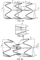
- FIG. 2A is a detail of the example shown in FIG. 1B , showing notch 44 defined by control rod 34 at distal end 38, and wherein ligature 42 traverses notch 44, as more clearly shown in detail in FIG. 2B , whereby rotation of control rod 34 causes ligature 42 to be releasably fixed to control rod 34 and thereby cause ligature 42 to wrap around control rod 34 by rotation of control rod 34, about its longitudinal axis 48, as shown in FIG. 2C . Wrapping of ligature 42 about control rod 34 causes constriction of radially self-expanding stent 26. As also shown in FIGs. 2A-2C , ligature 42 traverses struts 28 attached to outside surface 16 of stent graft 12.
- ligature 42 penetrates luminal graft component 14 on either lateral side of strut 28, whereby ligature 42 traverses strut 28 while passing across inside surface 18 of luminal graft component 14.
- Release of control rod 34 allows ligature 42 to unwind from control rod 34 by expansion of radial stent 26, such as by radial self expansion of stent 26 where stent 26 is fabricated of a suitable shape memory alloy, such as Nitinol.
- control rod 34 can be rotated in the opposite direction to thereby allow expansion of stent 26 which, in yet another example, can be a stent that does not radially self-expand, but, rather, expands by virtue of some other mechanism known in the art, such as a balloon catheter (not shown).
- stent 26 which, in yet another example, can be a stent that does not radially self-expand, but, rather, expands by virtue of some other mechanism known in the art, such as a balloon catheter (not shown).
- the position of stent 26, ligature 42 and control rod 34 can return to that shown in FIGs. 2A and 2B following at least one of axial and longitudinal positioning of stent graft 12 at an arterial aneurysm. It is to be understood that the radial expansion and radial constriction of stent 26 can be variably controlled by control rod 34 until at least one of axial and longitudinal positioning is complete.
- Control rod 34 is then separated from ligature 42.
- Ligature 42 is released from control rod 34 and control rod 34 can be removed from the stent graft 12 at the arterial aneurysm by proximally retracting control rod 34, in the direction indicated by arrow 35 as can be seen in the transition from FIGs. 2A through FIG. 2D .
- control rod 34, ligature 42 and stents 26 can be varied and still obtain the same result.
- radial stents can be located at inside surface 18 of stent graft 12, rather than, as shown in FIGs. 2A-2D , outside surface 16.
- control rod 34 can extend along inside surface 18 of stent graft 12, rather than, as shown in FIGs. 2A-2D , along outside surface 16 of stent graft 12.
- the ligature 42 when releasably fixed to control rod 34 extending longitudinally within stent graft 12, can radially constrict stent 12 by passing through luminal graft component 14 of stent graft 12 and traversing struts 26 while passing across outside surface 16 of stent graft.
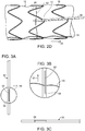
- FIG. 3A is a side view of another example of a control rod of the stent graft delivery system.
- control rod 50 defines slot 52 extending generally longitudinally along control rod 50 at distal end 54.
- Ligature 56 can be captured within slot 52, which is accessible at opening 58 of slot 52 as can be seen in FIG. 3B .
- Opening 58 of slot 52 is a partial transverse cut at one end of longitudinal slot, as shown in FIGs. 3B and 3C .
- Rotation of control rod 50 about its longitudinal axis wraps ligature 56 about control rod 50.
- Ligature 56 can be released from control rod 50 by retracting control rod 50 in a proximal direction, indicated by arrow 57, thereby causing ligature 56 to be drawn out of slot 52 through opening 58.
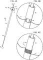
- control rod 60 includes tube 62 having proximal end 64 and distal end 66. Slot 68 is at distal end 66. Wire 70 extends longitudinally through tube 62.
- FIG. 4B which is a detail taken from FIG. 4A
- ligature 71 is threaded between wire 70 and tube 62 at slot 68, whereby rotation of tube 62 about wire 70 causes ligature 71 to wind about the outside surface of tube 62, as shown in FIG. 4C .
- Ligature 71 can be released from control rod 60 by unwinding ligature from tube 62 and retracting wire 70 from traversing slot 68, or, in some instances, by only proximally retracting wire 70 from traversing slot 68.
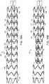
- FIG. 5 is an exploded view of another embodiment of a control rod of a stent graft delivery system of the invention.
- control rod 70 includes outer tube 72 defining outer tube fenestration 74.
- Inner tube 76 defines inner tube fenestration 78.
- Inner tube 76 has a diameter smaller than that of an inside diameter of outer tube 72.
- Wire 80 has a diameter smaller than an interior diameter of inner tube 76.
- wire 80 extends longitudinally through the inner tube 76, and inner tube 76 extends longitudinally within outer tube 72, inner tube fenestration 78 is aligned with outer tube fenestration 74, and wire 80 traverses both inner tube fenestration 76 and outer tube fenestration 74.
- FIG. 7A is a side view of an embodiment of the stent graft delivery system of the invention, wherein control rod 70 of FIGs. 5 and 6 extends longitudinally along stent graft 82 at outside surface 84.
- Ligature 86 is threaded between wire 80 and an inside surface of inner tube 76 while inner tube fenestration 78 and outer tube fenestration 74 are aligned.
- Stent 88 of stent graft 82 can be radially constricted by retracting or advancing inner tube 76 within outer tube 72, thereby causing ligature 86 to be drawn within outer tube 72.
- ligature 86 is stabilized, at least in part, by at least one ligature suture 87 spanning ligature 86.
- control rod 70, ligature 86 and stent 88 relative to each other can take different forms, as discussed with respect to the embodiments described above.
- stent 88 is constricted by proximally pulling ligature 86 into the outer tube 72 by retraction of inner tube 76 longitudinally and wire 80 in the direction indicated by arrow 73, if necessary, within outer tube 72, as can be seen in the transition from FIG. 7A to FIG. 7B .
- ligature 86 shown in this embodiment traversing under struts 89 of stent 88, is radially constricted by rotating inner tube 76 to thereby radially constrict stent 88, struts 89 of which are traversed by ligature 86, as can be seen in the transition from FIG. 7A to FIG. 7C .
- ligature 86 traverses over at least one strut 89 of stent 88 of stent graft 82. It is understood that ligatures of the stent grafts of other embodiments of the delivery systems of the invention described above can also include ligatures that traverse an outside portion at least one strut of a stent of the stent graft. As shown in FIG. 8 , ligature suture 87 secures ligature 86 to a position traversing the outwardly facing portion of struts 89 of stent 88.
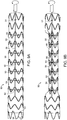
- FIG. 9A Another embodiment of a stent graft delivery system of the invention is shown in FIG. 9A .
- stent graft delivery system 90 includes a plurality of ligatures 92 that extend about the perimeter of stents 94 at stent graft 96, whereby rotation of control rod 98 of stent graft 96 causes uniform constriction of respective stents.
- axially rotating control rod 98 causes ligatures 92 to wrap around control rod 98, thereby radially constricting stents 94 traversed by ligatures 92 linked to control rod 98.
- At least one loop 91 secures control rod 98 to luminal graft component 95 of stent graft 96.
- at least one loop 93 secures ligatures 92 to luminal graft component 95.
- Bare stent 97 is at the proximal open end and includes proximal apices 99 and distal apices 83, which, optionally, include barbs (not shown).
- Stent graft delivery system 100 includes a plurality of control rods 102,104 each separately and independently control radial constriction of different portions or sets, of stents 106 of stent graft 108 by independent rotation of the control rods 102,104. For example, as can be seen in the transition from FIG. 10A to FIG.
- ligatures 109 and, therefore, first control rod 102 which is linked to ligatures at proximal portion of stents 111, is axially rotated to thereby radially constrict ligatures 109 and stent graft 108 at the proximal portion of stents 111 to a radially constricted position.
- first control rod 102 which is linked to ligatures at proximal portion of stents 111, is axially rotated to thereby radially constrict ligatures 109 and stent graft 108 at the proximal portion of stents 111 to a radially constricted position.
- Bare stent 112 is at the proximal open end of the stent graft 108 and includes proximal apices 114 and distal apices 113 and, optionally, barbs at at least one of proximal apices 114 and distal apices 113 (not shown).
- both first control rod 102 and second control rod 104 are axially rotated to thereby radially constrict ligatures 109,110 and the proximal and distal portions of stents 111 and stent graft 108 at ligatures 109,110 linked to the first control rod 102 and second control rod 104, to cause stent graft 108 to be in a radially constricted position.
- at least one of loops 101,103 secure at least one of first control rod 102 and second control rod 104, respectively, to luminal graft component 105 of stent graft 108.
- At least one loop 107 secures ligatures 110 of a second control rod 104 at the distal portion of stents 111 and at least one loop (not shown) secures ligatures 109 of first control rod 102 at the proximal portion of stents 111.
- the stent graft delivery system of the invention can include a plurality of control rods that each separately and independently control radial expansion of the same portion of stents, in particular a proximal portion of stents.
- the plurality of control rods are laterally and longitudinally arranged relative to each other about a circumference of the outside or inside surface of the luminal graft component (not shown).
- control rods can be employed in the device of the invention to independently radially constrict various longitudinal portions of a stent graft, such as proximal and distal portions of a stent graft.
- a plurality of control rods can be distributed radially about a stent graft, either evenly, evenly in conjunction with a fenestration in the stent graft, or in another pattern or unevenly.
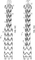
- FIG. 11 is an exploded view of another embodiment of a stent graft delivery system of the invention.
- stent graft delivery system 120 includes guidewire catheter 122 having proximal end 124 and distal end 126.
- Proximal handle 128 is fixed to proximal end 124 of guidewire catheter 122.
- Nose cone 130 is fixed to distal end 126 of guidewire catheter 122.
- Control rod 132 includes proximal end 134 and distal end 136.
- Control rod handle 138 is fixed to proximal end 134 of control rod 132.
- Stent graft 140 includes luminal graft component 142 and stents 144.
- Stents 144 include struts 146 that define proximal and distal apices. Ligature 148 traverses struts of stent.
- Introducer sheath 150 includes proximal end 152 and distal end 154. Distal handle 156 is fixed to proximal end 152 of introducer sheath 150.
- FIG. 12A is a side view of the stent graft of the delivery system shown in FIG. 11 , but when assembled, and wherein a stent graft 140 has been loaded within distal end 154 of introducer sheath 150.
- stent graft 140 includes bare stent 121 at proximal open end 152 having proximal apices and distal apices that, optionally, include barbs.
- FIG. 12B is a side view of a stent graft delivery system of FIGs. 11 and 12A , following direction of stent graft delivery system 120 to arterial aneurysm site 158 of a patient such as an aortic aneurysm, and location of stent graft 140 of stent graft delivery system 120 at a position spanning aneurysm site 158. As further shown in FIG. 12B , stent graft 140 is located at arterial aneurysm 158, such as is shown in the transition between FIGs.
- stent graft 140 is exposed to aneurysm site 158 by retraction of distal handle 156 toward proximal handle 128 by the surgeon in the direction indicated by arrow 170.
- stent graft 140 can be advanced from within introducer sheath 150 at distal end 159 to arterial aneurysm 158 by advancing proximal handle 128 and control rod 132 toward distal handle 156 in the direction of arrow 172.
- the length of the portion of ligature 148 traversing stent can be increased or decreased controllable by axial rotation of control rod handle 138 and consequent rotation of control rod 132 by the surgeon during positioning of stent graft 140 at aneurysm 158.
- stent graft 140 is positioned so that fenestration 164 at stent graft 140 is properly aligned with arterial branch 160 for subsequent placement of branch prosthesis 162 through fenestration 164 to arterial branch 160.
- ligature 148 Upon completion of positioning of stent graft at aneurysm site 158, ligature 148 is released from control rod 132.
- ligature 148 can be released from control rod 132 by proximally retracting control rod 132, as shown in the transition from FIG. 12B to FIG. 12C , or, by other means, such as by proximal retraction of a wire within a tube, as described above with reference to the embodiments of FIGs. 4A-4B and FIGs. 5-7C , thereby releasing ligature 148.
- Deployment of stent graft 140 then is complete.
- stent graft delivery system 120 portions of stent graft delivery system 120 that are no longer linked to stent graft 140 are retracted from stent graft 140 and, if appropriate, branch prosthesis 162 is directed through stent graft 140 and fenestration 164 of stent graft 140 into arterial branch 160, thereby completing treatment of arterial aneurysm 158.
- ligature 148 can be adjusted not only by rotation of control rod 132, but maintained (in embodiments not shown) at a select position by fixing the position of control rod handle 138 by a suitable means, such as by biasing control rod handle 138 toward proximal handle 128 or distal handle 156, or by some other means. Bias of the control handle 138 can be obtained by a spring, friction, an interference fit or ratcheting between the control rod handle and another component of the delivery device, such as proximal handle 128 or distal handle 156.
- a plurality of ligatures can be secured to control rod, whereby each ligature extends about a perimeter of a stent, whereby rotation of the control rod causes uniform constriction of the respective stents. It is also to be understood that more than a single control rod can be employed, whereby each control rod separately and independently controls a different stent.
- Vascular prostheses implanted by the stent graft systems of the invention can be implanted, for example, by transfemoral access. Additional branch prostheses that are directed into the vascular prostheses of the invention can be implanted, for example, by supraaortic vessel access (e.g., through the brachial artery), or by transfemoral access, or access from some other branch or branches of major blood vessels, including peripheral blood vessels.
Claims (15)
- Système de pose d'endoprothèse (10), comprenant :a) une endoprothèse (12) qui comportei) un composant de greffe luminal (14) ayant une surface extérieure (16), une surface intérieure (18), une extrémité proximale ouverte (20), une extrémité distale ouverte (22), et définissant une lumière (24), etii) une pluralité de stents (26) s'étendant longitudinalement le long du composant de greffe luminal (14) ;b) une tige de commande (60) s'étendant longitudinalement le long du composant de greffe luminal (14), la tige de commande (60) comportant un fil (70) et une tige luminale interne (62) qui définit une fenestration interne (68), moyennant quoi le fil (70) peut s'étendre à travers la tige luminale interne (62) ; etc) au moins une ligature (71) traversant au moins l'un des stents (26) et fixée de manière commandable et amovible à la tige de commande (62), la ligature (71) s'étendant entre la tige luminale (62) et le fil (70) et à travers la fenestration interne (68), et la ligature (71) étant commandée par rotation axiale de la tige de commande (60), moyennant quoi la ligature (71) s'enroule autour de la tige de commande (60) pour commander ainsi la constriction du stent traversé (26), moyennant quoi la commande de la ligature (71) au niveau de la tige de commande (60) comprime radialement le stent traversé (26).
- Système de pose d'endoprothèse (10) selon la revendication 1, comportant en outre :a) un cathéter à fil-guide (122) s'étendant à travers la lumière de l'endoprothèse (140), le cathéter à fil-guide (122) ayant une extrémité proximale (124) et une extrémité distale (126) ;b) une pointe avant (130) fixée à l'extrémité distale (126) du cathéter à fil-guide (122) ;c) une poignée proximale (128) à l'extrémité proximale (124) du cathéter à fil-guide (122) ;d) une gaine d'introducteur (150) qui contient au moins partiellement l'endoprothèse (140) et la tige de commande (132), la gaine d'introducteur (150) ayant une extrémité proximale (152) et une extrémité distale (154) ; ete) une poignée distale (156) à l'extrémité proximale ouverte (152) de la gaine d'introducteur (150).
- Système de pose d'endoprothèse (10) selon la revendication 1, dans lequel la tige de commande (132) comporte en outre une poignée de tige de commande (138) à une extrémité proximale (134) de la tige de commande (132).
- Système de pose d'endoprothèse (10) selon la revendication 3, dans lequel la poignée de tige de commande (138) est sollicitée soit vers la poignée proximale (128) soit vers la poignée distale (156), moyennant quoi la libération de la poignée de tige de commande (138) par le chirurgien amènera la poignée de tige de commande (138) à se verrouiller en rotation avec la poignée proximale (128) ou la poignée distale (156).
- Système de pose d'endoprothèse (10) selon la revendication 4, dans lequel la poignée de tige de commande (138) se verrouille en rotation soit avec la poignée proximale (128) soit avec la poignée distale (156) par au moins un élément du groupe constitué d'une friction, d'un ajustement serré et d'un encliquetage.
- Système de pose d'endoprothèse (10) selon la revendication 1, dans lequel le fil (70) est rétractable depuis l'intérieur de la tige luminale (62), libérant ainsi la ligature (71).
- Système de pose d'endoprothèse (10) selon la revendication 1, dans lequel la tige de commande comporte en outre une tige luminale externe (72) définissant une fenestration externe (74), la fenestration interne (78) de la tige luminale interne (76) étant alignée avec la fenestration externe (74), et le fil (80) s'étendant à l'intérieur de la tige interne (76) et traversant à la fois les fenestrations externe (74) et interne (78) de la tige de commande (70), la ligature traversant les fenestrations alignées (74, 78) des tiges luminales externe (72) et interne (76), et la ligature (86) s'étendant entre les tiges luminales interne (76) et externe (72) et le fil (80), moyennant quoi l'endoprothèse (82) peut être compressée par au moins l'un de la rétractation, l'avancement et/ou la rotation de la tige luminale interne (76) par rapport à la tige luminale externe (72), et être libérée de la tige de commande (70) en rétractant le fil (80) depuis la tige luminale interne (76).
- Système de pose d'endoprothèse (10) selon la revendication 1, dans lequel la tige de commande (70) s'étend le long de la surface extérieure de l'endoprothèse (82).
- Système de pose d'endoprothèse (10) selon la revendication 8, dans lequel l'endoprothèse (88) traversée par la ligature (86) est radialement auto-expansible et comporte des entretoises (89) qui définissent des sommets, la ligature (86) traversant les entretoises (89) de l'endoprothèse (88), et moyennant quoi la constriction radiale du stent (88) par la tige de commande (70) est intrinsèquement réversible, la ligature (42) passant facultativement à travers le composant de greffe luminal (14) et traversant facultativement les entretoises (28) du stent (26) au niveau de parties de la ligature (42) qui sont du côté opposé du composant de greffe luminal (14) par rapport aux entretoises (28).
- Système de pose d'endoprothèse (10) selon la revendication 1, comportant une pluralité de ligatures (92) fixées de manière commandable et amovible à la tige de commande (98) et réparties le long de la tige de commande (98), au moins une partie des ligatures (92) traversant chacune un stent (88) de l'endoprothèse (82), moyennant quoi la commande de la ligature (92) de la tige de commande (98) comprime les stents radialement auto-expansibles traversés (88) à l'unisson.
- Système de pose d'endoprothèse (10) selon la revendication 1, comportant une pluralité de tiges de commande (102, 104), et une ligature (109, 110) fixée de manière commandable et amovible à chaque tige de commande (102, 104), moyennant quoi une constriction autour des stents traversés (106) respectifs des prothèses de l'endoprothèse (96) peut être commandée indépendamment.
- Système de pose d'endoprothèse (10) selon la revendication 1, dans lequel la tige de commande (34) s'étend à l'intérieur de la lumière (24) du composant de greffe luminal (14), le stent (26) au niveau de la ligature (42) comportant facultativement des entretoises (28) qui définissent des sommets, et la ligature (42) traversant les entretoises (28) du stent (26), en outre la ligature (42) passant facultativement à travers le composant de greffe luminal (14) et traversant les entretoises (28) du stent (26) au niveau des parties de la ligature (42) qui sont du côté opposé du composant de greffe luminal (14) par rapport aux entretoises (28).
- Système de pose d'endoprothèse (10) selon la revendication 9 ou la revendication 12, dans lequel le stent (26) traversé par la ligature (42) s'étend autour de :a) la surface externe (16) du composant de greffe luminal (14) de l'endoprothèse (12), et la ligature (42) traverse l'entretoise (28) du stent traversé (26) au niveau des parties de la ligature (42) qui se trouvent au niveau de la surface intérieure (18) du composant de greffe luminal (14), oub) la surface intérieure (18) du composant de greffe luminal (14) de l'endoprothèse (12), et la ligature (42) traverse les entretoises (28) du stent traversé (26) au niveau des parties de la ligature (42) qui se trouvent au niveau de la surface extérieure (16) du composant de greffe luminal (14).
- Système de pose d'endoprothèse (10) selon la revendication 1, dans lequel le composant de greffe luminal (140) définit une fenestration (164).
- Système de pose d'endoprothèse (10) selon la revendication 14, dans lequel la fenestration (164) est bordée au moins de manière proximale ou distale par le stent (144) commandé par la ligature (148), la fenestration (164) étant facultativement bordée à la fois de manière proximale et distale par les stents (144) commandés par les ligatures (148).
Applications Claiming Priority (2)
| Application Number | Priority Date | Filing Date | Title |
|---|---|---|---|
| US201762463066P | 2017-02-24 | 2017-02-24 | |
| PCT/US2018/019356 WO2018156854A1 (fr) | 2017-02-24 | 2018-02-23 | Système de pose d'endoprothèse à ajustement radial |
Publications (2)
| Publication Number | Publication Date |
|---|---|
| EP3534838A1 EP3534838A1 (fr) | 2019-09-11 |
| EP3534838B1 true EP3534838B1 (fr) | 2021-01-27 |
Family
ID=61599631
Family Applications (1)
| Application Number | Title | Priority Date | Filing Date |
|---|---|---|---|
| EP18709883.5A Active EP3534838B1 (fr) | 2017-02-24 | 2018-02-23 | Système de pose d'endoprothèse à ajustement radial |
Country Status (6)
| Country | Link |
|---|---|
| US (2) | US11219540B2 (fr) |
| EP (1) | EP3534838B1 (fr) |
| JP (1) | JP7065091B2 (fr) |
| CN (1) | CN110114037B (fr) |
| ES (1) | ES2859485T3 (fr) |
| WO (1) | WO2018156854A1 (fr) |
Families Citing this family (18)
| Publication number | Priority date | Publication date | Assignee | Title |
|---|---|---|---|---|
| US7763063B2 (en) | 2003-09-03 | 2010-07-27 | Bolton Medical, Inc. | Self-aligning stent graft delivery system, kit, and method |
| JP6227542B2 (ja) | 2011-11-11 | 2017-11-08 | ボルトン メディカル インコーポレイテッド | ユニバーサル血管内グラフト |
| WO2018026768A1 (fr) | 2016-08-02 | 2018-02-08 | Aortica Corporation | Systèmes, dispositifs et procédés pour accoupler un implant prothétique à un corps fenêtré |
| CN110022795B (zh) | 2017-02-24 | 2023-03-14 | 波顿医疗公司 | 能够受约束的支架移植物、递送系统及使用方法 |
| WO2018156847A1 (fr) | 2017-02-24 | 2018-08-30 | Bolton Medical, Inc. | Système de pose et procédé de constriction radiale d'une endoprothèse couverte |
| EP3534848B1 (fr) | 2017-02-24 | 2023-06-28 | Bolton Medical, Inc. | Système de mise en place de greffe d'endoprothèse présentant une gaine rétrécie |
| ES2863978T3 (es) | 2017-02-24 | 2021-10-13 | Bolton Medical Inc | Sistema para constreñir radialmente un injerto de stent |
| WO2018156850A1 (fr) | 2017-02-24 | 2018-08-30 | Bolton Medical, Inc. | Endoprothèse couverte comprenant un verrou de fenestration |
| CN109843226B (zh) | 2017-02-24 | 2022-05-17 | 波顿医疗公司 | 用于径向收缩支架移植物的递送系统和使用方法 |
| WO2018156848A1 (fr) | 2017-02-24 | 2018-08-30 | Bolton Medical, Inc. | Prothèse vasculaire à adaptateur serti et procédés d'utilisation |
| CN111148484B (zh) | 2017-09-25 | 2022-12-30 | 波尔顿医疗公司 | 用于将假体植入物联接到开窗体的系统、装置和方法 |
| EP4049633A1 (fr) | 2017-10-31 | 2022-08-31 | Bolton Medical, Inc. | Composant de couple distal, système d'administration et leur procédé d'utilisation |
| CN109984862A (zh) * | 2017-12-29 | 2019-07-09 | 杭州唯强医疗科技有限公司 | 一种可分步释放的主动脉覆膜支架 |
| WO2020160476A2 (fr) | 2019-02-01 | 2020-08-06 | Bolton Medical, Inc. | Endoprothèses luminales expansibles et procédés d'utilisation |
| CN112891033B (zh) * | 2019-12-03 | 2023-07-04 | 先健科技(深圳)有限公司 | 管腔支架 |
| DE102020209823A1 (de) * | 2020-08-04 | 2022-02-10 | EPflex Feinwerktechnik GmbH. | Rohrinstrument mit selbstexpandierender Drahtstruktur |
| WO2022265989A1 (fr) | 2021-06-14 | 2022-12-22 | Bolton Medical, Inc. | Réparation aortique vasculaire à anneau de support et procédés d'utilisation |
| WO2022265985A1 (fr) | 2021-06-14 | 2022-12-22 | Bolton Medical, Inc. | Bague de support, prothèse aortique et procédé de formation |
Family Cites Families (117)
| Publication number | Priority date | Publication date | Assignee | Title |
|---|---|---|---|---|
| US5123917A (en) | 1990-04-27 | 1992-06-23 | Lee Peter Y | Expandable intraluminal vascular graft |
| US5242452A (en) | 1991-10-11 | 1993-09-07 | Kanji Inoue | Device for collapsing an appliance collapsible for insertion into human organs |
| FR2688401B1 (fr) | 1992-03-12 | 1998-02-27 | Thierry Richard | Endoprothese expansible pour organe tubulaire humain ou animal, et outil de mise en place. |
| US5507769A (en) | 1994-10-18 | 1996-04-16 | Stentco, Inc. | Method and apparatus for forming an endoluminal bifurcated graft |
| US6113623A (en) | 1994-04-20 | 2000-09-05 | Cabinet Beau De Lomenie | Prosthetic device and method for eventration repair |
| US6015429A (en) * | 1994-09-08 | 2000-01-18 | Gore Enterprise Holdings, Inc. | Procedures for introducing stents and stent-grafts |
| US5713948A (en) | 1995-07-19 | 1998-02-03 | Uflacker; Renan | Adjustable and retrievable graft and graft delivery system for stent-graft system |
| US6878161B2 (en) | 1996-01-05 | 2005-04-12 | Medtronic Vascular, Inc. | Stent graft loading and deployment device and method |
| CA2258732C (fr) | 1996-06-20 | 2006-04-04 | Sulzer Vascutek Ltd. | Reconstitution prothetique de conduits du corps humain |
| AUPO700897A0 (en) | 1997-05-26 | 1997-06-19 | William A Cook Australia Pty Ltd | A method and means of deploying a graft |
| US5910144A (en) | 1998-01-09 | 1999-06-08 | Endovascular Technologies, Inc. | Prosthesis gripping system and method |
| US6395018B1 (en) | 1998-02-09 | 2002-05-28 | Wilfrido R. Castaneda | Endovascular graft and process for bridging a defect in a main vessel near one of more branch vessels |
| US6171334B1 (en) | 1998-06-17 | 2001-01-09 | Advanced Cardiovascular Systems, Inc. | Expandable stent and method of use |
| GB2365356A (en) | 1999-05-07 | 2002-02-20 | Salviac Ltd | An embolic protection device |
| US6648912B2 (en) | 2000-02-15 | 2003-11-18 | Eva Corporation | Temporary stent assembly for use in a surgical procedure |
| US6761733B2 (en) | 2001-04-11 | 2004-07-13 | Trivascular, Inc. | Delivery system and method for bifurcated endovascular graft |
| US6821291B2 (en) * | 2001-06-01 | 2004-11-23 | Ams Research Corporation | Retrievable stent and method of use thereof |
| US20020193872A1 (en) | 2001-06-18 | 2002-12-19 | Trout Hugh H. | Prosthetic graft assembly and method of use |
| JP4608673B2 (ja) * | 2001-09-19 | 2011-01-12 | Junken Medical株式会社 | ステント及びステント付きグラフト |
| WO2004017868A1 (fr) | 2002-08-23 | 2004-03-04 | William A. Cook Australia Pty. Ltd. | Fixation asymetrique de stent greffe |
| US20050131523A1 (en) | 2003-04-02 | 2005-06-16 | Mehran Bashiri | Detachable and retrievable stent assembly |
| US9198786B2 (en) | 2003-09-03 | 2015-12-01 | Bolton Medical, Inc. | Lumen repair device with capture structure |
| US8500792B2 (en) | 2003-09-03 | 2013-08-06 | Bolton Medical, Inc. | Dual capture device for stent graft delivery system and method for capturing a stent graft |
| US8292943B2 (en) | 2003-09-03 | 2012-10-23 | Bolton Medical, Inc. | Stent graft with longitudinal support member |
| US7763063B2 (en) | 2003-09-03 | 2010-07-27 | Bolton Medical, Inc. | Self-aligning stent graft delivery system, kit, and method |
| US20080264102A1 (en) | 2004-02-23 | 2008-10-30 | Bolton Medical, Inc. | Sheath Capture Device for Stent Graft Delivery System and Method for Operating Same |
| US7413573B2 (en) | 2003-10-10 | 2008-08-19 | William A. Cook Australia Pty. Ltd. | Fenestrated stent grafts |
| JP4846590B2 (ja) | 2003-10-10 | 2011-12-28 | ウィリアム・エイ・クック・オーストラリア・プロプライエタリー・リミテッド | ステントグラフト開窓 |
| EP1682042B1 (fr) | 2003-10-10 | 2015-09-02 | Cook Medical Technologies LLC | Extenseur-greffon composite |
| EP1673040B1 (fr) | 2003-10-10 | 2008-07-30 | Cook Incorporated | Fenetre pour prothese extensible |
| US20050096725A1 (en) | 2003-10-29 | 2005-05-05 | Pomeranz Mark L. | Expandable stent having removable slat members |
| FR2863160B1 (fr) | 2003-12-09 | 2006-03-03 | Perouse Laboratoires | Dispositif de traitement d'un vaisseau sanguin et procede de preparation de ce dispositif |
| US8308789B2 (en) | 2004-07-16 | 2012-11-13 | W. L. Gore & Associates, Inc. | Deployment system for intraluminal devices |
| US7758626B2 (en) | 2004-07-20 | 2010-07-20 | Medtronic Vascular, Inc. | Device and method for delivering an endovascular stent-graft having a longitudinally unsupported portion |
| JP2008514370A (ja) | 2004-09-28 | 2008-05-08 | ウィリアム・エイ・クック・オーストラリア・プロプライエタリー・リミテッド | 大動脈解離治療用装置 |
| US7918880B2 (en) | 2005-02-16 | 2011-04-05 | Boston Scientific Scimed, Inc. | Self-expanding stent and delivery system |
| AU2006280948B2 (en) | 2005-08-18 | 2011-10-27 | Cook Incorporated | Assembly of stent grafts |
| US8911491B2 (en) | 2005-09-02 | 2014-12-16 | Medtronic Vascular, Inc. | Methods and apparatus for treatment of aneurysms adjacent branch arteries including branch artery flow lumen alignment |
| US8435284B2 (en) | 2005-12-14 | 2013-05-07 | Boston Scientific Scimed, Inc. | Telescoping bifurcated stent |
| US9155641B2 (en) | 2006-03-09 | 2015-10-13 | Cook Medical Technologies Llc | Expandable stent grafts |
| US7678141B2 (en) | 2006-04-18 | 2010-03-16 | Medtronic Vascular, Inc. | Stent graft having a flexible, articulable, and axially compressible branch graft |
| US20070244547A1 (en) | 2006-04-18 | 2007-10-18 | Medtronic Vascular, Inc., A Delaware Corporation | Device and Method for Controlling the Positioning of a Stent Graft Fenestration |
| US9259336B2 (en) | 2006-06-06 | 2016-02-16 | Cook Medical Technologies Llc | Stent with a crush-resistant zone |
| US9358142B2 (en) | 2007-04-24 | 2016-06-07 | W. L. Gore & Associates, Inc. | Catheter having guidewire channel |
| US8377113B2 (en) | 2007-05-11 | 2013-02-19 | William A. Cook Austraila Pty. Ltd. | Stent grafts for the thoracic aorta |
| US7637940B2 (en) | 2007-07-06 | 2009-12-29 | Boston Scientific Scimed, Inc. | Stent with bioabsorbable membrane |
| WO2009102435A1 (fr) * | 2008-02-13 | 2009-08-20 | William Cook Europe Aps | Appareil et procédé d'ajustement d'une greffe d’endoprothèse vasculaire ou d'un dispositif similaire |
| US8974518B2 (en) * | 2008-03-25 | 2015-03-10 | Medtronic Vascular, Inc. | Eversible branch stent-graft and deployment method |
| US8236040B2 (en) | 2008-04-11 | 2012-08-07 | Endologix, Inc. | Bifurcated graft deployment systems and methods |
| US20100049294A1 (en) | 2008-06-04 | 2010-02-25 | Zukowski Stanislaw L | Controlled deployable medical device and method of making the same |
| FR2932979B1 (fr) | 2008-06-25 | 2012-04-06 | Perouse Lab | Dispositif introducteur s'etendant entre un point proximal et un point distal et necessaire de traitement associe. |
| CN107961098A (zh) | 2008-06-30 | 2018-04-27 | 波顿医疗公司 | 用于腹主动脉瘤的系统和方法 |
| JP5134729B2 (ja) | 2008-07-01 | 2013-01-30 | エンドロジックス、インク | カテーテルシステム |
| US8353943B2 (en) | 2008-08-29 | 2013-01-15 | Cook Medical Technologies Llc | Variable weave graft with metal strand reinforcement for in situ fenestration |
| AU2009292193B2 (en) | 2008-09-12 | 2013-06-20 | Cook Incorporated | Radiopaque reinforcing member |
| US8137398B2 (en) * | 2008-10-13 | 2012-03-20 | Medtronic Ventor Technologies Ltd | Prosthetic valve having tapered tip when compressed for delivery |
| GB2464978B (en) | 2008-10-31 | 2010-10-20 | Cook William Europ | Introducer for deploying a stent graft in a curved lumen |
| CN106551740B (zh) | 2009-03-13 | 2020-03-27 | 波顿医疗公司 | 用于在手术部位部署腔内假体的系统和方法 |
| US8945202B2 (en) | 2009-04-28 | 2015-02-03 | Endologix, Inc. | Fenestrated prosthesis |
| AU2009202301B8 (en) | 2009-06-10 | 2009-12-03 | Cook Incorporated | Reinforcing ring |
| WO2011014814A2 (fr) | 2009-07-30 | 2011-02-03 | Boston Scientific Scimed, Inc. | Système de mise en place dune endoprothèse |
| US8845682B2 (en) * | 2009-10-13 | 2014-09-30 | E-Pacing, Inc. | Vasculature closure devices and methods |
| US8926693B2 (en) | 2010-02-17 | 2015-01-06 | Medtronic, Inc. | Heart valve delivery catheter with safety button |
| US8764811B2 (en) | 2010-04-20 | 2014-07-01 | Medtronic Vascular, Inc. | Controlled tip release stent graft delivery system and method |
| US9101455B2 (en) | 2010-08-13 | 2015-08-11 | Cook Medical Technologies Llc | Preloaded wire for endoluminal device |
| US8702786B2 (en) | 2010-08-21 | 2014-04-22 | Cook Medical Technologies Llc | Prosthesis having pivoting fenestration |
| US8870939B2 (en) | 2010-08-21 | 2014-10-28 | Cook Medical Technologies Llc | Prosthesis having pivoting fenestration |
| CN101933855B (zh) * | 2010-08-26 | 2013-06-12 | 先健科技(深圳)有限公司 | 一种可回收的血管支架 |
| US9198787B2 (en) * | 2010-12-31 | 2015-12-01 | Cook Medical Technologies Llc | Conformable prosthesis delivery system and method for deployment thereof |
| WO2012096687A1 (fr) * | 2011-01-14 | 2012-07-19 | Idev Technologies, Inc | Système de pose d'endoprothèse comportant un ensemble pousseur |
| US8641752B1 (en) | 2011-01-20 | 2014-02-04 | W. L. Gore & Associates, Inc. | Integrated sheath and deployment |
| US9155619B2 (en) | 2011-02-25 | 2015-10-13 | Edwards Lifesciences Corporation | Prosthetic heart valve delivery apparatus |
| US9839542B2 (en) | 2011-04-19 | 2017-12-12 | Medtronic Ardian Luxembourg S.A.R.L. | Mobile external coupling for branch vessel connection |
| US8840659B2 (en) | 2011-04-28 | 2014-09-23 | Cook Medical Technologies Llc | Stent and stent-graft designs |
| EP2701640B1 (fr) | 2011-04-29 | 2020-12-30 | Evasc Neurovascular Enterprises ULC | Prothèse endovasculaire |
| US8728148B2 (en) | 2011-11-09 | 2014-05-20 | Cook Medical Technologies Llc | Diameter reducing tie arrangement for endoluminal prosthesis |
| US9387097B2 (en) | 2011-11-16 | 2016-07-12 | W. L. Gore & Associates, Inc. | Implant assembly with tactile indicator |
| CN106420107B (zh) | 2011-11-16 | 2019-02-05 | 波顿医疗公司 | 用于主动脉分支血管的修复的装置和方法 |
| CN110064076A (zh) | 2012-01-16 | 2019-07-30 | 麦瑞通医疗设备有限公司 | 被旋转纺丝材料覆盖的医疗器械和制造方法 |
| DE102012101103B3 (de) | 2012-02-10 | 2013-07-04 | Jotec Gmbh | Stentgraft mit Fixierelementen und Einführsystem |
| US9375308B2 (en) | 2012-03-13 | 2016-06-28 | W. L. Gore & Associates, Inc. | External steerable fiber for use in endoluminal deployment of expandable devices |
| WO2013154749A1 (fr) | 2012-04-12 | 2013-10-17 | Bolton Medical, Inc. | Dispositif de mise en place d'une prothèse vasculaire et son procédé d'utilisation |
| US9095421B2 (en) | 2012-04-18 | 2015-08-04 | Medtronic Vascular, Inc. | Multi-leaflet coupling for branch vessel connection |
| US8968384B2 (en) | 2012-04-27 | 2015-03-03 | Medtronic Vascular, Inc. | Circumferentially constraining sutures for a stent-graft |
| EP2879627A4 (fr) | 2012-08-01 | 2016-04-13 | Endospan Ltd | Endoprothèses conçues pour une expansion post-implantation |
| US20140052232A1 (en) | 2012-08-10 | 2014-02-20 | Altura Medical, Inc. | Handle assemblies for stent graft delivery systems and associated systems and methods |
| AU2012258394B1 (en) | 2012-11-27 | 2013-03-07 | Cook Medical Technologies Llc | Stent graft having a closeable fenestration |
| AU2012258395B1 (en) * | 2012-11-27 | 2013-03-28 | Cook Medical Technologies Llc | Assembly of stent grafts with diameter reducing ties |
| CN103349577B (zh) * | 2012-11-30 | 2015-05-06 | 宁波健世生物科技有限公司 | 带远端保护的经皮主动脉支架或主动脉瓣膜支架系统 |
| EP2745813A1 (fr) | 2012-12-18 | 2014-06-25 | Cook Medical Technologies LLC | Fil préchargé pour dispositif endoluminal |
| US9498361B2 (en) * | 2012-12-19 | 2016-11-22 | Cook Medical Technologies Llc | Repositionable diameter constraints |
| US10350096B2 (en) | 2012-12-26 | 2019-07-16 | Cook Medical Technologies Llc | Expandable stent-graft system having diameter reducing connectors |
| CN103908356A (zh) | 2012-12-28 | 2014-07-09 | 库克医学技术有限责任公司 | 具有枢转开窗部的假体 |
| CN104027187B (zh) | 2013-03-04 | 2016-05-25 | 微创心脉医疗科技(上海)有限公司 | 分支型覆膜支架、包括其的输送系统及其制造方法 |
| ES2683908T3 (es) | 2013-03-15 | 2018-09-28 | Bolton Medical, Inc. | Válvula hemostática y sistemas de dispensación |
| US9439751B2 (en) | 2013-03-15 | 2016-09-13 | Bolton Medical, Inc. | Hemostasis valve and delivery systems |
| WO2014162306A2 (fr) * | 2013-04-02 | 2014-10-09 | Tendyne Holdings, Inc. | Dispositifs et procédés améliorés pour valves cardiaques prothétiques à transcathéter |
| WO2014201380A1 (fr) | 2013-06-14 | 2014-12-18 | Altai Medical Technologies | Filtre de veine cave inférieure et systèmes de retrait |
| WO2015057838A1 (fr) | 2013-10-15 | 2015-04-23 | Boston Scientific Scimed, Inc. | Procédés et systèmes de chargement et de pose d'une endoprothèse |
| CN104622600B (zh) | 2013-11-15 | 2017-12-19 | 微创心脉医疗科技(上海)有限公司 | 一种术中支架系统 |
| US10603197B2 (en) | 2013-11-19 | 2020-03-31 | Endospan Ltd. | Stent system with radial-expansion locking |
| AU2014200124B1 (en) | 2014-01-08 | 2014-10-02 | Cook Medical Technologies Llc | A stent graft and delivery device having a low profile |
| EP3145453B1 (fr) | 2014-05-21 | 2021-01-20 | Boston Scientific Scimed, Inc. | Système de pose d'endoprothèse |
| BR112017012425A2 (pt) | 2014-12-18 | 2018-01-02 | Endospan Ltd | enxerto por stent endovascular com tubo lateral resistente à fadiga |
| US10092428B2 (en) * | 2014-12-30 | 2018-10-09 | Cook Medical Technologies Llc | Low profile prosthesis delivery device |
| US20160184078A1 (en) | 2014-12-31 | 2016-06-30 | Cordis Corporation | Sectional Inserts for Trunk Section in Endoprosthesis for Aortic Aneurysm |
| WO2016115007A1 (fr) | 2015-01-14 | 2016-07-21 | Cook Medical Technologies Llc | Suture et système de déploiement d'endoprothèse |
| KR102467761B1 (ko) | 2015-01-28 | 2022-11-15 | 아오틱 이노베이션즈 엘엘씨 | 모듈형 대동맥내 장치 및 그러한 장치의 사용 방법 |
| EP3078349B1 (fr) | 2015-04-10 | 2019-06-19 | Cook Medical Technologies LLC | Prothèse avec fenêtrage |
| US20160361088A1 (en) * | 2015-06-12 | 2016-12-15 | Covidien Lp | Catheter with pre-formed geometry for body lumen access |
| FR3042702B1 (fr) | 2015-10-26 | 2021-12-24 | Id Nest Medical | Couronne elastique et dispositif de traitement associe pour une implantation dans un conduit de circulation d'un fluide corporel |
| CN105943213B (zh) * | 2015-12-23 | 2019-01-04 | 微创心脉医疗科技(上海)有限公司 | 支架输送系统及其使用方法 |
| JP2019510579A (ja) | 2016-04-05 | 2019-04-18 | ボルトン メディカル インコーポレイテッド | イントロデューサーシースおよび遠位シースを有する送達システムならびに使用方法 |
| CN105832447A (zh) | 2016-05-27 | 2016-08-10 | 杨威 | 主动脉夹层手术用覆膜支架、输送装置及其使用方法 |
| ES2860458T3 (es) | 2016-06-13 | 2021-10-05 | Aortica Corp | Sistemas y dispositivos para marcar y/o reforzar fenestraciones en implantes protésicos |
| US10433991B2 (en) | 2016-07-18 | 2019-10-08 | Cook Medical Technologies Llc | Controlled expansion stent graft delivery system |
| WO2018026768A1 (fr) | 2016-08-02 | 2018-02-08 | Aortica Corporation | Systèmes, dispositifs et procédés pour accoupler un implant prothétique à un corps fenêtré |
-
2018
- 2018-02-23 JP JP2019528076A patent/JP7065091B2/ja active Active
- 2018-02-23 CN CN201880004586.5A patent/CN110114037B/zh active Active
- 2018-02-23 ES ES18709883T patent/ES2859485T3/es active Active
- 2018-02-23 EP EP18709883.5A patent/EP3534838B1/fr active Active
- 2018-02-23 WO PCT/US2018/019356 patent/WO2018156854A1/fr unknown
-
2019
- 2019-05-16 US US16/414,132 patent/US11219540B2/en active Active
-
2021
- 2021-12-01 US US17/539,514 patent/US20220087841A1/en active Pending
Non-Patent Citations (1)
| Title |
|---|
| None * |
Also Published As
| Publication number | Publication date |
|---|---|
| US11219540B2 (en) | 2022-01-11 |
| WO2018156854A1 (fr) | 2018-08-30 |
| EP3534838A1 (fr) | 2019-09-11 |
| US20220087841A1 (en) | 2022-03-24 |
| JP2020508088A (ja) | 2020-03-19 |
| US20190269537A1 (en) | 2019-09-05 |
| ES2859485T3 (es) | 2021-10-04 |
| CN110114037A (zh) | 2019-08-09 |
| CN110114037B (zh) | 2022-07-12 |
| JP7065091B2 (ja) | 2022-05-11 |
Similar Documents
| Publication | Publication Date | Title |
|---|---|---|
| EP3534838B1 (fr) | Système de pose d'endoprothèse à ajustement radial | |
| US11491003B2 (en) | Constrainable stent graft, delivery system and methods of use | |
| US20220313464A1 (en) | Method for implanting a stent graft | |
| EP3932373B1 (fr) | Système de mise en place pour la constriction radiale d'une greffe de stent | |
| EP3585306B1 (fr) | Système de constriction radiale d'une endoprothèse | |
| JP2020508086A (ja) | シースが収縮されたステントグラフト送達システムおよび使用方法 | |
| JP2022544399A (ja) | 人工血管 |
Legal Events
| Date | Code | Title | Description |
|---|---|---|---|
| STAA | Information on the status of an ep patent application or granted ep patent |
Free format text: STATUS: UNKNOWN |
|
| STAA | Information on the status of an ep patent application or granted ep patent |
Free format text: STATUS: THE INTERNATIONAL PUBLICATION HAS BEEN MADE |
|
| PUAI | Public reference made under article 153(3) epc to a published international application that has entered the european phase |
Free format text: ORIGINAL CODE: 0009012 |
|
| STAA | Information on the status of an ep patent application or granted ep patent |
Free format text: STATUS: REQUEST FOR EXAMINATION WAS MADE |
|
| 17P | Request for examination filed |
Effective date: 20190604 |
|
| AK | Designated contracting states |
Kind code of ref document: A1 Designated state(s): AL AT BE BG CH CY CZ DE DK EE ES FI FR GB GR HR HU IE IS IT LI LT LU LV MC MK MT NL NO PL PT RO RS SE SI SK SM TR |
|
| AX | Request for extension of the european patent |
Extension state: BA ME |
|
| DAV | Request for validation of the european patent (deleted) | ||
| DAX | Request for extension of the european patent (deleted) | ||
| GRAP | Despatch of communication of intention to grant a patent |
Free format text: ORIGINAL CODE: EPIDOSNIGR1 |
|
| STAA | Information on the status of an ep patent application or granted ep patent |
Free format text: STATUS: GRANT OF PATENT IS INTENDED |
|
| INTG | Intention to grant announced |
Effective date: 20200824 |
|
| GRAS | Grant fee paid |
Free format text: ORIGINAL CODE: EPIDOSNIGR3 |
|
| GRAA | (expected) grant |
Free format text: ORIGINAL CODE: 0009210 |
|
| STAA | Information on the status of an ep patent application or granted ep patent |
Free format text: STATUS: THE PATENT HAS BEEN GRANTED |
|
| AK | Designated contracting states |
Kind code of ref document: B1 Designated state(s): AL AT BE BG CH CY CZ DE DK EE ES FI FR GB GR HR HU IE IS IT LI LT LU LV MC MK MT NL NO PL PT RO RS SE SI SK SM TR |
|
| REG | Reference to a national code |
Ref country code: GB Ref legal event code: FG4D |
|
| REG | Reference to a national code |
Ref country code: CH Ref legal event code: EP |
|
| REG | Reference to a national code |
Ref country code: AT Ref legal event code: REF Ref document number: 1357666 Country of ref document: AT Kind code of ref document: T Effective date: 20210215 |
|
| REG | Reference to a national code |
Ref country code: IE Ref legal event code: FG4D |
|
| REG | Reference to a national code |
Ref country code: DE Ref legal event code: R096 Ref document number: 602018012317 Country of ref document: DE |
|
| REG | Reference to a national code |
Ref country code: DE Ref legal event code: R082 Ref document number: 602018012317 Country of ref document: DE Representative=s name: WR SERVICES GMBH, DE |
|
| REG | Reference to a national code |
Ref country code: NL Ref legal event code: MP Effective date: 20210127 |
|
| REG | Reference to a national code |
Ref country code: LT Ref legal event code: MG9D |
|
| REG | Reference to a national code |
Ref country code: AT Ref legal event code: MK05 Ref document number: 1357666 Country of ref document: AT Kind code of ref document: T Effective date: 20210127 |
|
| PG25 | Lapsed in a contracting state [announced via postgrant information from national office to epo] |
Ref country code: HR Free format text: LAPSE BECAUSE OF FAILURE TO SUBMIT A TRANSLATION OF THE DESCRIPTION OR TO PAY THE FEE WITHIN THE PRESCRIBED TIME-LIMIT Effective date: 20210127 Ref country code: GR Free format text: LAPSE BECAUSE OF FAILURE TO SUBMIT A TRANSLATION OF THE DESCRIPTION OR TO PAY THE FEE WITHIN THE PRESCRIBED TIME-LIMIT Effective date: 20210428 Ref country code: FI Free format text: LAPSE BECAUSE OF FAILURE TO SUBMIT A TRANSLATION OF THE DESCRIPTION OR TO PAY THE FEE WITHIN THE PRESCRIBED TIME-LIMIT Effective date: 20210127 Ref country code: BG Free format text: LAPSE BECAUSE OF FAILURE TO SUBMIT A TRANSLATION OF THE DESCRIPTION OR TO PAY THE FEE WITHIN THE PRESCRIBED TIME-LIMIT Effective date: 20210427 Ref country code: PT Free format text: LAPSE BECAUSE OF FAILURE TO SUBMIT A TRANSLATION OF THE DESCRIPTION OR TO PAY THE FEE WITHIN THE PRESCRIBED TIME-LIMIT Effective date: 20210527 Ref country code: NO Free format text: LAPSE BECAUSE OF FAILURE TO SUBMIT A TRANSLATION OF THE DESCRIPTION OR TO PAY THE FEE WITHIN THE PRESCRIBED TIME-LIMIT Effective date: 20210427 Ref country code: LT Free format text: LAPSE BECAUSE OF FAILURE TO SUBMIT A TRANSLATION OF THE DESCRIPTION OR TO PAY THE FEE WITHIN THE PRESCRIBED TIME-LIMIT Effective date: 20210127 |
|
| PG25 | Lapsed in a contracting state [announced via postgrant information from national office to epo] |
Ref country code: SE Free format text: LAPSE BECAUSE OF FAILURE TO SUBMIT A TRANSLATION OF THE DESCRIPTION OR TO PAY THE FEE WITHIN THE PRESCRIBED TIME-LIMIT Effective date: 20210127 Ref country code: LV Free format text: LAPSE BECAUSE OF FAILURE TO SUBMIT A TRANSLATION OF THE DESCRIPTION OR TO PAY THE FEE WITHIN THE PRESCRIBED TIME-LIMIT Effective date: 20210127 Ref country code: PL Free format text: LAPSE BECAUSE OF FAILURE TO SUBMIT A TRANSLATION OF THE DESCRIPTION OR TO PAY THE FEE WITHIN THE PRESCRIBED TIME-LIMIT Effective date: 20210127 Ref country code: RS Free format text: LAPSE BECAUSE OF FAILURE TO SUBMIT A TRANSLATION OF THE DESCRIPTION OR TO PAY THE FEE WITHIN THE PRESCRIBED TIME-LIMIT Effective date: 20210127 Ref country code: AT Free format text: LAPSE BECAUSE OF FAILURE TO SUBMIT A TRANSLATION OF THE DESCRIPTION OR TO PAY THE FEE WITHIN THE PRESCRIBED TIME-LIMIT Effective date: 20210127 |
|
| PG25 | Lapsed in a contracting state [announced via postgrant information from national office to epo] |
Ref country code: IS Free format text: LAPSE BECAUSE OF FAILURE TO SUBMIT A TRANSLATION OF THE DESCRIPTION OR TO PAY THE FEE WITHIN THE PRESCRIBED TIME-LIMIT Effective date: 20210527 |
|
| REG | Reference to a national code |
Ref country code: ES Ref legal event code: FG2A Ref document number: 2859485 Country of ref document: ES Kind code of ref document: T3 Effective date: 20211004 |
|
| REG | Reference to a national code |
Ref country code: BE Ref legal event code: MM Effective date: 20210228 |
|
| REG | Reference to a national code |
Ref country code: DE Ref legal event code: R097 Ref document number: 602018012317 Country of ref document: DE |
|
| PG25 | Lapsed in a contracting state [announced via postgrant information from national office to epo] |
Ref country code: EE Free format text: LAPSE BECAUSE OF FAILURE TO SUBMIT A TRANSLATION OF THE DESCRIPTION OR TO PAY THE FEE WITHIN THE PRESCRIBED TIME-LIMIT Effective date: 20210127 Ref country code: CZ Free format text: LAPSE BECAUSE OF FAILURE TO SUBMIT A TRANSLATION OF THE DESCRIPTION OR TO PAY THE FEE WITHIN THE PRESCRIBED TIME-LIMIT Effective date: 20210127 Ref country code: MC Free format text: LAPSE BECAUSE OF FAILURE TO SUBMIT A TRANSLATION OF THE DESCRIPTION OR TO PAY THE FEE WITHIN THE PRESCRIBED TIME-LIMIT Effective date: 20210127 Ref country code: LU Free format text: LAPSE BECAUSE OF NON-PAYMENT OF DUE FEES Effective date: 20210223 Ref country code: LI Free format text: LAPSE BECAUSE OF NON-PAYMENT OF DUE FEES Effective date: 20210228 Ref country code: SM Free format text: LAPSE BECAUSE OF FAILURE TO SUBMIT A TRANSLATION OF THE DESCRIPTION OR TO PAY THE FEE WITHIN THE PRESCRIBED TIME-LIMIT Effective date: 20210127 Ref country code: CH Free format text: LAPSE BECAUSE OF NON-PAYMENT OF DUE FEES Effective date: 20210228 |
|
| PG25 | Lapsed in a contracting state [announced via postgrant information from national office to epo] |
Ref country code: RO Free format text: LAPSE BECAUSE OF FAILURE TO SUBMIT A TRANSLATION OF THE DESCRIPTION OR TO PAY THE FEE WITHIN THE PRESCRIBED TIME-LIMIT Effective date: 20210127 Ref country code: SK Free format text: LAPSE BECAUSE OF FAILURE TO SUBMIT A TRANSLATION OF THE DESCRIPTION OR TO PAY THE FEE WITHIN THE PRESCRIBED TIME-LIMIT Effective date: 20210127 Ref country code: DK Free format text: LAPSE BECAUSE OF FAILURE TO SUBMIT A TRANSLATION OF THE DESCRIPTION OR TO PAY THE FEE WITHIN THE PRESCRIBED TIME-LIMIT Effective date: 20210127 |
|
| PLBE | No opposition filed within time limit |
Free format text: ORIGINAL CODE: 0009261 |
|
| STAA | Information on the status of an ep patent application or granted ep patent |
Free format text: STATUS: NO OPPOSITION FILED WITHIN TIME LIMIT |
|
| 26N | No opposition filed |
Effective date: 20211028 |
|
| PG25 | Lapsed in a contracting state [announced via postgrant information from national office to epo] |
Ref country code: AL Free format text: LAPSE BECAUSE OF FAILURE TO SUBMIT A TRANSLATION OF THE DESCRIPTION OR TO PAY THE FEE WITHIN THE PRESCRIBED TIME-LIMIT Effective date: 20210127 |
|
| PG25 | Lapsed in a contracting state [announced via postgrant information from national office to epo] |
Ref country code: SI Free format text: LAPSE BECAUSE OF FAILURE TO SUBMIT A TRANSLATION OF THE DESCRIPTION OR TO PAY THE FEE WITHIN THE PRESCRIBED TIME-LIMIT Effective date: 20210127 |
|
| PG25 | Lapsed in a contracting state [announced via postgrant information from national office to epo] |
Ref country code: IS Free format text: LAPSE BECAUSE OF FAILURE TO SUBMIT A TRANSLATION OF THE DESCRIPTION OR TO PAY THE FEE WITHIN THE PRESCRIBED TIME-LIMIT Effective date: 20210527 |
|
| PG25 | Lapsed in a contracting state [announced via postgrant information from national office to epo] |
Ref country code: BE Free format text: LAPSE BECAUSE OF NON-PAYMENT OF DUE FEES Effective date: 20210228 |
|
| PGFP | Annual fee paid to national office [announced via postgrant information from national office to epo] |
Ref country code: ES Payment date: 20230310 Year of fee payment: 6 |
|
| PGFP | Annual fee paid to national office [announced via postgrant information from national office to epo] |
Ref country code: IT Payment date: 20230110 Year of fee payment: 6 Ref country code: GB Payment date: 20230105 Year of fee payment: 6 Ref country code: DE Payment date: 20221229 Year of fee payment: 6 |
|
| PG25 | Lapsed in a contracting state [announced via postgrant information from national office to epo] |
Ref country code: NL Free format text: LAPSE BECAUSE OF NON-PAYMENT OF DUE FEES Effective date: 20210127 Ref country code: CY Free format text: LAPSE BECAUSE OF FAILURE TO SUBMIT A TRANSLATION OF THE DESCRIPTION OR TO PAY THE FEE WITHIN THE PRESCRIBED TIME-LIMIT Effective date: 20210127 |
|
| P01 | Opt-out of the competence of the unified patent court (upc) registered |
Effective date: 20230526 |
|
| PG25 | Lapsed in a contracting state [announced via postgrant information from national office to epo] |
Ref country code: HU Free format text: LAPSE BECAUSE OF FAILURE TO SUBMIT A TRANSLATION OF THE DESCRIPTION OR TO PAY THE FEE WITHIN THE PRESCRIBED TIME-LIMIT; INVALID AB INITIO Effective date: 20180223 |
|
| PGFP | Annual fee paid to national office [announced via postgrant information from national office to epo] |
Ref country code: IE Payment date: 20231211 Year of fee payment: 7 Ref country code: FR Payment date: 20231229 Year of fee payment: 7 |
|
| PGFP | Annual fee paid to national office [announced via postgrant information from national office to epo] |
Ref country code: ES Payment date: 20240305 Year of fee payment: 7 |
|
| PG25 | Lapsed in a contracting state [announced via postgrant information from national office to epo] |
Ref country code: MK Free format text: LAPSE BECAUSE OF FAILURE TO SUBMIT A TRANSLATION OF THE DESCRIPTION OR TO PAY THE FEE WITHIN THE PRESCRIBED TIME-LIMIT Effective date: 20210127 |
|
| PGFP | Annual fee paid to national office [announced via postgrant information from national office to epo] |
Ref country code: DE Payment date: 20231228 Year of fee payment: 7 Ref country code: GB Payment date: 20240108 Year of fee payment: 7 |