EP3534838B1 - Radial verstellbares stentgrafteinführungssystem - Google Patents
Radial verstellbares stentgrafteinführungssystem Download PDFInfo
- Publication number
- EP3534838B1 EP3534838B1 EP18709883.5A EP18709883A EP3534838B1 EP 3534838 B1 EP3534838 B1 EP 3534838B1 EP 18709883 A EP18709883 A EP 18709883A EP 3534838 B1 EP3534838 B1 EP 3534838B1
- Authority
- EP
- European Patent Office
- Prior art keywords
- ligature
- stent
- control rod
- stent graft
- luminal
- Prior art date
- Legal status (The legal status is an assumption and is not a legal conclusion. Google has not performed a legal analysis and makes no representation as to the accuracy of the status listed.)
- Active
Links
Images


Classifications
-
- A—HUMAN NECESSITIES
- A61—MEDICAL OR VETERINARY SCIENCE; HYGIENE
- A61F—FILTERS IMPLANTABLE INTO BLOOD VESSELS; PROSTHESES; DEVICES PROVIDING PATENCY TO, OR PREVENTING COLLAPSING OF, TUBULAR STRUCTURES OF THE BODY, e.g. STENTS; ORTHOPAEDIC, NURSING OR CONTRACEPTIVE DEVICES; FOMENTATION; TREATMENT OR PROTECTION OF EYES OR EARS; BANDAGES, DRESSINGS OR ABSORBENT PADS; FIRST-AID KITS
- A61F2/00—Filters implantable into blood vessels; Prostheses, i.e. artificial substitutes or replacements for parts of the body; Appliances for connecting them with the body; Devices providing patency to, or preventing collapsing of, tubular structures of the body, e.g. stents
- A61F2/95—Instruments specially adapted for placement or removal of stents or stent-grafts
-
- A—HUMAN NECESSITIES
- A61—MEDICAL OR VETERINARY SCIENCE; HYGIENE
- A61F—FILTERS IMPLANTABLE INTO BLOOD VESSELS; PROSTHESES; DEVICES PROVIDING PATENCY TO, OR PREVENTING COLLAPSING OF, TUBULAR STRUCTURES OF THE BODY, e.g. STENTS; ORTHOPAEDIC, NURSING OR CONTRACEPTIVE DEVICES; FOMENTATION; TREATMENT OR PROTECTION OF EYES OR EARS; BANDAGES, DRESSINGS OR ABSORBENT PADS; FIRST-AID KITS
- A61F2/00—Filters implantable into blood vessels; Prostheses, i.e. artificial substitutes or replacements for parts of the body; Appliances for connecting them with the body; Devices providing patency to, or preventing collapsing of, tubular structures of the body, e.g. stents
- A61F2/02—Prostheses implantable into the body
- A61F2/04—Hollow or tubular parts of organs, e.g. bladders, tracheae, bronchi or bile ducts
- A61F2/06—Blood vessels
- A61F2/07—Stent-grafts
-
- A—HUMAN NECESSITIES
- A61—MEDICAL OR VETERINARY SCIENCE; HYGIENE
- A61M—DEVICES FOR INTRODUCING MEDIA INTO, OR ONTO, THE BODY; DEVICES FOR TRANSDUCING BODY MEDIA OR FOR TAKING MEDIA FROM THE BODY; DEVICES FOR PRODUCING OR ENDING SLEEP OR STUPOR
- A61M25/00—Catheters; Hollow probes
- A61M25/01—Introducing, guiding, advancing, emplacing or holding catheters
- A61M25/09—Guide wires
-
- A—HUMAN NECESSITIES
- A61—MEDICAL OR VETERINARY SCIENCE; HYGIENE
- A61F—FILTERS IMPLANTABLE INTO BLOOD VESSELS; PROSTHESES; DEVICES PROVIDING PATENCY TO, OR PREVENTING COLLAPSING OF, TUBULAR STRUCTURES OF THE BODY, e.g. STENTS; ORTHOPAEDIC, NURSING OR CONTRACEPTIVE DEVICES; FOMENTATION; TREATMENT OR PROTECTION OF EYES OR EARS; BANDAGES, DRESSINGS OR ABSORBENT PADS; FIRST-AID KITS
- A61F2/00—Filters implantable into blood vessels; Prostheses, i.e. artificial substitutes or replacements for parts of the body; Appliances for connecting them with the body; Devices providing patency to, or preventing collapsing of, tubular structures of the body, e.g. stents
- A61F2/82—Devices providing patency to, or preventing collapsing of, tubular structures of the body, e.g. stents
- A61F2/86—Stents in a form characterised by the wire-like elements; Stents in the form characterised by a net-like or mesh-like structure
- A61F2/90—Stents in a form characterised by the wire-like elements; Stents in the form characterised by a net-like or mesh-like structure characterised by a net-like or mesh-like structure
-
- A—HUMAN NECESSITIES
- A61—MEDICAL OR VETERINARY SCIENCE; HYGIENE
- A61F—FILTERS IMPLANTABLE INTO BLOOD VESSELS; PROSTHESES; DEVICES PROVIDING PATENCY TO, OR PREVENTING COLLAPSING OF, TUBULAR STRUCTURES OF THE BODY, e.g. STENTS; ORTHOPAEDIC, NURSING OR CONTRACEPTIVE DEVICES; FOMENTATION; TREATMENT OR PROTECTION OF EYES OR EARS; BANDAGES, DRESSINGS OR ABSORBENT PADS; FIRST-AID KITS
- A61F2/00—Filters implantable into blood vessels; Prostheses, i.e. artificial substitutes or replacements for parts of the body; Appliances for connecting them with the body; Devices providing patency to, or preventing collapsing of, tubular structures of the body, e.g. stents
- A61F2/95—Instruments specially adapted for placement or removal of stents or stent-grafts
- A61F2/9517—Instruments specially adapted for placement or removal of stents or stent-grafts handle assemblies therefor
-
- A—HUMAN NECESSITIES
- A61—MEDICAL OR VETERINARY SCIENCE; HYGIENE
- A61F—FILTERS IMPLANTABLE INTO BLOOD VESSELS; PROSTHESES; DEVICES PROVIDING PATENCY TO, OR PREVENTING COLLAPSING OF, TUBULAR STRUCTURES OF THE BODY, e.g. STENTS; ORTHOPAEDIC, NURSING OR CONTRACEPTIVE DEVICES; FOMENTATION; TREATMENT OR PROTECTION OF EYES OR EARS; BANDAGES, DRESSINGS OR ABSORBENT PADS; FIRST-AID KITS
- A61F2/00—Filters implantable into blood vessels; Prostheses, i.e. artificial substitutes or replacements for parts of the body; Appliances for connecting them with the body; Devices providing patency to, or preventing collapsing of, tubular structures of the body, e.g. stents
- A61F2/95—Instruments specially adapted for placement or removal of stents or stent-grafts
- A61F2/9522—Means for mounting a stent or stent-graft onto or into a placement instrument
-
- A—HUMAN NECESSITIES
- A61—MEDICAL OR VETERINARY SCIENCE; HYGIENE
- A61F—FILTERS IMPLANTABLE INTO BLOOD VESSELS; PROSTHESES; DEVICES PROVIDING PATENCY TO, OR PREVENTING COLLAPSING OF, TUBULAR STRUCTURES OF THE BODY, e.g. STENTS; ORTHOPAEDIC, NURSING OR CONTRACEPTIVE DEVICES; FOMENTATION; TREATMENT OR PROTECTION OF EYES OR EARS; BANDAGES, DRESSINGS OR ABSORBENT PADS; FIRST-AID KITS
- A61F2/00—Filters implantable into blood vessels; Prostheses, i.e. artificial substitutes or replacements for parts of the body; Appliances for connecting them with the body; Devices providing patency to, or preventing collapsing of, tubular structures of the body, e.g. stents
- A61F2/02—Prostheses implantable into the body
- A61F2/04—Hollow or tubular parts of organs, e.g. bladders, tracheae, bronchi or bile ducts
- A61F2/06—Blood vessels
- A61F2/07—Stent-grafts
- A61F2002/075—Stent-grafts the stent being loosely attached to the graft material, e.g. by stitching
-
- A—HUMAN NECESSITIES
- A61—MEDICAL OR VETERINARY SCIENCE; HYGIENE
- A61F—FILTERS IMPLANTABLE INTO BLOOD VESSELS; PROSTHESES; DEVICES PROVIDING PATENCY TO, OR PREVENTING COLLAPSING OF, TUBULAR STRUCTURES OF THE BODY, e.g. STENTS; ORTHOPAEDIC, NURSING OR CONTRACEPTIVE DEVICES; FOMENTATION; TREATMENT OR PROTECTION OF EYES OR EARS; BANDAGES, DRESSINGS OR ABSORBENT PADS; FIRST-AID KITS
- A61F2/00—Filters implantable into blood vessels; Prostheses, i.e. artificial substitutes or replacements for parts of the body; Appliances for connecting them with the body; Devices providing patency to, or preventing collapsing of, tubular structures of the body, e.g. stents
- A61F2/82—Devices providing patency to, or preventing collapsing of, tubular structures of the body, e.g. stents
- A61F2002/826—Devices providing patency to, or preventing collapsing of, tubular structures of the body, e.g. stents more than one stent being applied sequentially
-
- A—HUMAN NECESSITIES
- A61—MEDICAL OR VETERINARY SCIENCE; HYGIENE
- A61F—FILTERS IMPLANTABLE INTO BLOOD VESSELS; PROSTHESES; DEVICES PROVIDING PATENCY TO, OR PREVENTING COLLAPSING OF, TUBULAR STRUCTURES OF THE BODY, e.g. STENTS; ORTHOPAEDIC, NURSING OR CONTRACEPTIVE DEVICES; FOMENTATION; TREATMENT OR PROTECTION OF EYES OR EARS; BANDAGES, DRESSINGS OR ABSORBENT PADS; FIRST-AID KITS
- A61F2/00—Filters implantable into blood vessels; Prostheses, i.e. artificial substitutes or replacements for parts of the body; Appliances for connecting them with the body; Devices providing patency to, or preventing collapsing of, tubular structures of the body, e.g. stents
- A61F2/95—Instruments specially adapted for placement or removal of stents or stent-grafts
- A61F2002/9505—Instruments specially adapted for placement or removal of stents or stent-grafts having retaining means other than an outer sleeve, e.g. male-female connector between stent and instrument
- A61F2002/9511—Instruments specially adapted for placement or removal of stents or stent-grafts having retaining means other than an outer sleeve, e.g. male-female connector between stent and instrument the retaining means being filaments or wires
-
- A—HUMAN NECESSITIES
- A61—MEDICAL OR VETERINARY SCIENCE; HYGIENE
- A61F—FILTERS IMPLANTABLE INTO BLOOD VESSELS; PROSTHESES; DEVICES PROVIDING PATENCY TO, OR PREVENTING COLLAPSING OF, TUBULAR STRUCTURES OF THE BODY, e.g. STENTS; ORTHOPAEDIC, NURSING OR CONTRACEPTIVE DEVICES; FOMENTATION; TREATMENT OR PROTECTION OF EYES OR EARS; BANDAGES, DRESSINGS OR ABSORBENT PADS; FIRST-AID KITS
- A61F2210/00—Particular material properties of prostheses classified in groups A61F2/00 - A61F2/26 or A61F2/82 or A61F9/00 or A61F11/00 or subgroups thereof
- A61F2210/0014—Particular material properties of prostheses classified in groups A61F2/00 - A61F2/26 or A61F2/82 or A61F9/00 or A61F11/00 or subgroups thereof using shape memory or superelastic materials, e.g. nitinol
-
- A—HUMAN NECESSITIES
- A61—MEDICAL OR VETERINARY SCIENCE; HYGIENE
- A61M—DEVICES FOR INTRODUCING MEDIA INTO, OR ONTO, THE BODY; DEVICES FOR TRANSDUCING BODY MEDIA OR FOR TAKING MEDIA FROM THE BODY; DEVICES FOR PRODUCING OR ENDING SLEEP OR STUPOR
- A61M25/00—Catheters; Hollow probes
- A61M25/01—Introducing, guiding, advancing, emplacing or holding catheters
- A61M25/09—Guide wires
- A61M2025/09008—Guide wires having a balloon
-
- A—HUMAN NECESSITIES
- A61—MEDICAL OR VETERINARY SCIENCE; HYGIENE
- A61M—DEVICES FOR INTRODUCING MEDIA INTO, OR ONTO, THE BODY; DEVICES FOR TRANSDUCING BODY MEDIA OR FOR TAKING MEDIA FROM THE BODY; DEVICES FOR PRODUCING OR ENDING SLEEP OR STUPOR
- A61M25/00—Catheters; Hollow probes
- A61M25/10—Balloon catheters
Definitions
- Arterial pathologies including aortic aneurysms, can be treated by open surgical reconstruction, or alternatively, endovascular repair, which is a minimally invasive alternative to open surgical repair.
- endovascular repair which is a minimally invasive alternative to open surgical repair.
- Optimizing a successful outcome of endovascular repair requires assessment of the patient's anatomy and, in the case of an aortic aneurysm, selection of an appropriate stent graft that spans the proximal and distal ends of the aneurysm to insure complete exclusion of the aneurysm sac, anchoring of the stent graft in the aorta, and minimal endoleaks.
- EP 2735283 A1 relates to an assembly of stent grafts with diameter reducing ties.
- US 2002/188344 A1 relates to a retrievable stent and method of use thereof.
- the present invention relates to a stent graft delivery system, as disclosed in claim 1.
- the physician can rotate or reposition the stent graft after it has been at least partially radially expanded, such as by only partially relaxing or reconstructing or reconstraining a ligature extending about stents of the stent graft by rotational movement of a control rod in which the ligature is wrapped.
- Axial or longitudinal repositioning of the reconstrained stent graft, or a portion thereof provides greater control over delivery systems that are only able to position the stent graft prior to full expansion of the stent graft within a blood vessel.
- a stent graft can be deployed at a surgical site with more accuracy, less risk of injury to the vasculature of the subject, and without significant risk of distorting the intended shape of the stent graft when implanted at the surgical site.
- the invention is generally directed to a stent graft delivery system that includes at least one control rod and at least one ligature that is releasably fixed to the control rod and about a stent of a stent graft.
- the stent graft delivery system and method are used to treat aortic vascular damage, such as vascular damage associated with an aortic aneurysms, including in regions of the aorta having arterial branches that supply blood to vital organs and tissues, such as juxtarenal aortic aneurysms and short-neck abdominal aortic aneurysms.
- proximal means that portion of the prosthesis or component of the prosthesis that is relatively close to the heart of the patient and “distal” means that portion of the prosthesis or component of the prosthesis that is relatively far from the heart of the patient.
- proximal means closer to the clinician using the delivery system.
- distal means, further away from the clinician using the delivery system.
- proximate means “close to,” as opposed to the meanings ascribed to “proximal” or “distal” described above with respect to either the prosthesis or a delivery system.
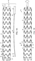
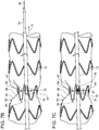
- stent graft delivery system 10 includes stent graft 12.
- Stent graft 12 includes luminal graft component 14 having outside surface 16, inside surface 18, proximal open end 20, distal open end 22, and defines lumen 24.
- a plurality of radial stents 26 extend longitudinally along luminal graft component 14.
- Stents 26 include struts 28 that are joined at opposite ends to thereby define proximal apices 30 and distal apices 32.
- Bare stent 21 is at proximal open end 20 and includes proximal apices 23 and distal apices 25.
- proximal apices 23 and distal apices 32 include barbs extending distally from bridge of eyelet (not shown). It is to be understood that in these examples, the proximal open ends of stent grafts of the delivery systems of the invention can be without bare stents (not shown).
- Control rod 34 includes proximal end 36 and distal end 38. Control rod handle 40 is fixed to proximal end 36 of control rod 34.
- control rod 34 extends longitudinally along stent graft 12 at least one of distal apices.
- Ligature 42 traverses radial stent 26 and is controllably and releasably fixed to the control rod 34.
- ligature 42 extends through notch 44 in control rod 34, and traverses struts 28 of radially self-expanding stent 26, whereby, according to one example of a method, and as can be seen in FIG.
- rotation of control rod 34 at ligature 42 causes ligature 42 to wrap about the control rod 34, thereby radially constricting the at least one radial stent 26 traversed by ligature 42.
- loop 33 secures control rod 34 to luminal graft component 14.
- ligature 42 passes under a portion of struts 28 of stent 26.
- ligature 42 cover struts 29 on either side of control rod 34 (not shown) and remaining portion of ligature 42 passes under remaining struts 28 of stent 26.
- radial stent 26 at ligature 42 is radially self-expanding, or is radially constrained in opposition to some other radially expanding force, such as a balloon catheter (not shown) as is known in the art.
- Radially self-expanding stents include those that are fabricated of, for example, a shape memory alloy, such as Nitinol. Examples of other suitable materials of fabrication of stents 26 include stainless steel and a suitable polymer.
- Ligature 42 and loop 33 are formed of a suitable material, such as is known in the art, including polyester, nylon, and polypropylene.
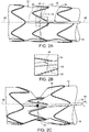
- FIG. 2A is a detail of the example shown in FIG. 1B , showing notch 44 defined by control rod 34 at distal end 38, and wherein ligature 42 traverses notch 44, as more clearly shown in detail in FIG. 2B , whereby rotation of control rod 34 causes ligature 42 to be releasably fixed to control rod 34 and thereby cause ligature 42 to wrap around control rod 34 by rotation of control rod 34, about its longitudinal axis 48, as shown in FIG. 2C . Wrapping of ligature 42 about control rod 34 causes constriction of radially self-expanding stent 26. As also shown in FIGs. 2A-2C , ligature 42 traverses struts 28 attached to outside surface 16 of stent graft 12.
- ligature 42 penetrates luminal graft component 14 on either lateral side of strut 28, whereby ligature 42 traverses strut 28 while passing across inside surface 18 of luminal graft component 14.
- Release of control rod 34 allows ligature 42 to unwind from control rod 34 by expansion of radial stent 26, such as by radial self expansion of stent 26 where stent 26 is fabricated of a suitable shape memory alloy, such as Nitinol.
- control rod 34 can be rotated in the opposite direction to thereby allow expansion of stent 26 which, in yet another example, can be a stent that does not radially self-expand, but, rather, expands by virtue of some other mechanism known in the art, such as a balloon catheter (not shown).
- stent 26 which, in yet another example, can be a stent that does not radially self-expand, but, rather, expands by virtue of some other mechanism known in the art, such as a balloon catheter (not shown).
- the position of stent 26, ligature 42 and control rod 34 can return to that shown in FIGs. 2A and 2B following at least one of axial and longitudinal positioning of stent graft 12 at an arterial aneurysm. It is to be understood that the radial expansion and radial constriction of stent 26 can be variably controlled by control rod 34 until at least one of axial and longitudinal positioning is complete.
- Control rod 34 is then separated from ligature 42.
- Ligature 42 is released from control rod 34 and control rod 34 can be removed from the stent graft 12 at the arterial aneurysm by proximally retracting control rod 34, in the direction indicated by arrow 35 as can be seen in the transition from FIGs. 2A through FIG. 2D .
- control rod 34, ligature 42 and stents 26 can be varied and still obtain the same result.
- radial stents can be located at inside surface 18 of stent graft 12, rather than, as shown in FIGs. 2A-2D , outside surface 16.
- control rod 34 can extend along inside surface 18 of stent graft 12, rather than, as shown in FIGs. 2A-2D , along outside surface 16 of stent graft 12.
- the ligature 42 when releasably fixed to control rod 34 extending longitudinally within stent graft 12, can radially constrict stent 12 by passing through luminal graft component 14 of stent graft 12 and traversing struts 26 while passing across outside surface 16 of stent graft.
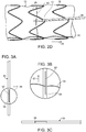
- FIG. 3A is a side view of another example of a control rod of the stent graft delivery system.
- control rod 50 defines slot 52 extending generally longitudinally along control rod 50 at distal end 54.
- Ligature 56 can be captured within slot 52, which is accessible at opening 58 of slot 52 as can be seen in FIG. 3B .
- Opening 58 of slot 52 is a partial transverse cut at one end of longitudinal slot, as shown in FIGs. 3B and 3C .
- Rotation of control rod 50 about its longitudinal axis wraps ligature 56 about control rod 50.
- Ligature 56 can be released from control rod 50 by retracting control rod 50 in a proximal direction, indicated by arrow 57, thereby causing ligature 56 to be drawn out of slot 52 through opening 58.
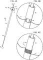
- control rod 60 includes tube 62 having proximal end 64 and distal end 66. Slot 68 is at distal end 66. Wire 70 extends longitudinally through tube 62.
- FIG. 4B which is a detail taken from FIG. 4A
- ligature 71 is threaded between wire 70 and tube 62 at slot 68, whereby rotation of tube 62 about wire 70 causes ligature 71 to wind about the outside surface of tube 62, as shown in FIG. 4C .
- Ligature 71 can be released from control rod 60 by unwinding ligature from tube 62 and retracting wire 70 from traversing slot 68, or, in some instances, by only proximally retracting wire 70 from traversing slot 68.
- FIG. 5 is an exploded view of another embodiment of a control rod of a stent graft delivery system of the invention.
- control rod 70 includes outer tube 72 defining outer tube fenestration 74.
- Inner tube 76 defines inner tube fenestration 78.
- Inner tube 76 has a diameter smaller than that of an inside diameter of outer tube 72.
- Wire 80 has a diameter smaller than an interior diameter of inner tube 76.
- wire 80 extends longitudinally through the inner tube 76, and inner tube 76 extends longitudinally within outer tube 72, inner tube fenestration 78 is aligned with outer tube fenestration 74, and wire 80 traverses both inner tube fenestration 76 and outer tube fenestration 74.
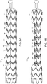
- FIG. 7A is a side view of an embodiment of the stent graft delivery system of the invention, wherein control rod 70 of FIGs. 5 and 6 extends longitudinally along stent graft 82 at outside surface 84.
- Ligature 86 is threaded between wire 80 and an inside surface of inner tube 76 while inner tube fenestration 78 and outer tube fenestration 74 are aligned.
- Stent 88 of stent graft 82 can be radially constricted by retracting or advancing inner tube 76 within outer tube 72, thereby causing ligature 86 to be drawn within outer tube 72.
- ligature 86 is stabilized, at least in part, by at least one ligature suture 87 spanning ligature 86.
- control rod 70, ligature 86 and stent 88 relative to each other can take different forms, as discussed with respect to the embodiments described above.
- stent 88 is constricted by proximally pulling ligature 86 into the outer tube 72 by retraction of inner tube 76 longitudinally and wire 80 in the direction indicated by arrow 73, if necessary, within outer tube 72, as can be seen in the transition from FIG. 7A to FIG. 7B .
- ligature 86 shown in this embodiment traversing under struts 89 of stent 88, is radially constricted by rotating inner tube 76 to thereby radially constrict stent 88, struts 89 of which are traversed by ligature 86, as can be seen in the transition from FIG. 7A to FIG. 7C .
- ligature 86 traverses over at least one strut 89 of stent 88 of stent graft 82. It is understood that ligatures of the stent grafts of other embodiments of the delivery systems of the invention described above can also include ligatures that traverse an outside portion at least one strut of a stent of the stent graft. As shown in FIG. 8 , ligature suture 87 secures ligature 86 to a position traversing the outwardly facing portion of struts 89 of stent 88.
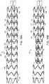
- FIG. 9A Another embodiment of a stent graft delivery system of the invention is shown in FIG. 9A .
- stent graft delivery system 90 includes a plurality of ligatures 92 that extend about the perimeter of stents 94 at stent graft 96, whereby rotation of control rod 98 of stent graft 96 causes uniform constriction of respective stents.
- axially rotating control rod 98 causes ligatures 92 to wrap around control rod 98, thereby radially constricting stents 94 traversed by ligatures 92 linked to control rod 98.
- At least one loop 91 secures control rod 98 to luminal graft component 95 of stent graft 96.
- at least one loop 93 secures ligatures 92 to luminal graft component 95.
- Bare stent 97 is at the proximal open end and includes proximal apices 99 and distal apices 83, which, optionally, include barbs (not shown).
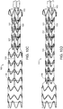
- Stent graft delivery system 100 includes a plurality of control rods 102,104 each separately and independently control radial constriction of different portions or sets, of stents 106 of stent graft 108 by independent rotation of the control rods 102,104. For example, as can be seen in the transition from FIG. 10A to FIG.
- ligatures 109 and, therefore, first control rod 102 which is linked to ligatures at proximal portion of stents 111, is axially rotated to thereby radially constrict ligatures 109 and stent graft 108 at the proximal portion of stents 111 to a radially constricted position.
- first control rod 102 which is linked to ligatures at proximal portion of stents 111, is axially rotated to thereby radially constrict ligatures 109 and stent graft 108 at the proximal portion of stents 111 to a radially constricted position.
- Bare stent 112 is at the proximal open end of the stent graft 108 and includes proximal apices 114 and distal apices 113 and, optionally, barbs at at least one of proximal apices 114 and distal apices 113 (not shown).
- both first control rod 102 and second control rod 104 are axially rotated to thereby radially constrict ligatures 109,110 and the proximal and distal portions of stents 111 and stent graft 108 at ligatures 109,110 linked to the first control rod 102 and second control rod 104, to cause stent graft 108 to be in a radially constricted position.
- at least one of loops 101,103 secure at least one of first control rod 102 and second control rod 104, respectively, to luminal graft component 105 of stent graft 108.
- At least one loop 107 secures ligatures 110 of a second control rod 104 at the distal portion of stents 111 and at least one loop (not shown) secures ligatures 109 of first control rod 102 at the proximal portion of stents 111.
- the stent graft delivery system of the invention can include a plurality of control rods that each separately and independently control radial expansion of the same portion of stents, in particular a proximal portion of stents.
- the plurality of control rods are laterally and longitudinally arranged relative to each other about a circumference of the outside or inside surface of the luminal graft component (not shown).
- control rods can be employed in the device of the invention to independently radially constrict various longitudinal portions of a stent graft, such as proximal and distal portions of a stent graft.
- a plurality of control rods can be distributed radially about a stent graft, either evenly, evenly in conjunction with a fenestration in the stent graft, or in another pattern or unevenly.
- FIG. 11 is an exploded view of another embodiment of a stent graft delivery system of the invention.
- stent graft delivery system 120 includes guidewire catheter 122 having proximal end 124 and distal end 126.
- Proximal handle 128 is fixed to proximal end 124 of guidewire catheter 122.
- Nose cone 130 is fixed to distal end 126 of guidewire catheter 122.
- Control rod 132 includes proximal end 134 and distal end 136.
- Control rod handle 138 is fixed to proximal end 134 of control rod 132.
- Stent graft 140 includes luminal graft component 142 and stents 144.
- Stents 144 include struts 146 that define proximal and distal apices. Ligature 148 traverses struts of stent.
- Introducer sheath 150 includes proximal end 152 and distal end 154. Distal handle 156 is fixed to proximal end 152 of introducer sheath 150.
- FIG. 12A is a side view of the stent graft of the delivery system shown in FIG. 11 , but when assembled, and wherein a stent graft 140 has been loaded within distal end 154 of introducer sheath 150.
- stent graft 140 includes bare stent 121 at proximal open end 152 having proximal apices and distal apices that, optionally, include barbs.
- FIG. 12B is a side view of a stent graft delivery system of FIGs. 11 and 12A , following direction of stent graft delivery system 120 to arterial aneurysm site 158 of a patient such as an aortic aneurysm, and location of stent graft 140 of stent graft delivery system 120 at a position spanning aneurysm site 158. As further shown in FIG. 12B , stent graft 140 is located at arterial aneurysm 158, such as is shown in the transition between FIGs.
- stent graft 140 is exposed to aneurysm site 158 by retraction of distal handle 156 toward proximal handle 128 by the surgeon in the direction indicated by arrow 170.
- stent graft 140 can be advanced from within introducer sheath 150 at distal end 159 to arterial aneurysm 158 by advancing proximal handle 128 and control rod 132 toward distal handle 156 in the direction of arrow 172.
- the length of the portion of ligature 148 traversing stent can be increased or decreased controllable by axial rotation of control rod handle 138 and consequent rotation of control rod 132 by the surgeon during positioning of stent graft 140 at aneurysm 158.
- stent graft 140 is positioned so that fenestration 164 at stent graft 140 is properly aligned with arterial branch 160 for subsequent placement of branch prosthesis 162 through fenestration 164 to arterial branch 160.
- ligature 148 Upon completion of positioning of stent graft at aneurysm site 158, ligature 148 is released from control rod 132.
- ligature 148 can be released from control rod 132 by proximally retracting control rod 132, as shown in the transition from FIG. 12B to FIG. 12C , or, by other means, such as by proximal retraction of a wire within a tube, as described above with reference to the embodiments of FIGs. 4A-4B and FIGs. 5-7C , thereby releasing ligature 148.
- Deployment of stent graft 140 then is complete.
- stent graft delivery system 120 portions of stent graft delivery system 120 that are no longer linked to stent graft 140 are retracted from stent graft 140 and, if appropriate, branch prosthesis 162 is directed through stent graft 140 and fenestration 164 of stent graft 140 into arterial branch 160, thereby completing treatment of arterial aneurysm 158.
- ligature 148 can be adjusted not only by rotation of control rod 132, but maintained (in embodiments not shown) at a select position by fixing the position of control rod handle 138 by a suitable means, such as by biasing control rod handle 138 toward proximal handle 128 or distal handle 156, or by some other means. Bias of the control handle 138 can be obtained by a spring, friction, an interference fit or ratcheting between the control rod handle and another component of the delivery device, such as proximal handle 128 or distal handle 156.
- a plurality of ligatures can be secured to control rod, whereby each ligature extends about a perimeter of a stent, whereby rotation of the control rod causes uniform constriction of the respective stents. It is also to be understood that more than a single control rod can be employed, whereby each control rod separately and independently controls a different stent.
- Vascular prostheses implanted by the stent graft systems of the invention can be implanted, for example, by transfemoral access. Additional branch prostheses that are directed into the vascular prostheses of the invention can be implanted, for example, by supraaortic vessel access (e.g., through the brachial artery), or by transfemoral access, or access from some other branch or branches of major blood vessels, including peripheral blood vessels.
Landscapes
- Health & Medical Sciences (AREA)
- Engineering & Computer Science (AREA)
- Biomedical Technology (AREA)
- Life Sciences & Earth Sciences (AREA)
- Animal Behavior & Ethology (AREA)
- Veterinary Medicine (AREA)
- Public Health (AREA)
- Heart & Thoracic Surgery (AREA)
- General Health & Medical Sciences (AREA)
- Transplantation (AREA)
- Vascular Medicine (AREA)
- Oral & Maxillofacial Surgery (AREA)
- Cardiology (AREA)
- Pulmonology (AREA)
- Gastroenterology & Hepatology (AREA)
- Biophysics (AREA)
- Anesthesiology (AREA)
- Hematology (AREA)
- Prostheses (AREA)
- Media Introduction/Drainage Providing Device (AREA)
Claims (15)
- Stentimplantat-Abgabesystem (10), umfassend:a) ein Stentimplantat (12), enthaltendi) eine Luminalimplantatkomponente (14), die eine Außenfläche (16), eine Innenfläche (18), ein proximales offenes Ende (20), ein distales offenes Ende (22) aufweist und ein Lumen (24) definiert, undii) mehrere Stents (26), die sich in Längsrichtung entlang der Luminalimplantatkomponente (14) erstrecken;b) einen Steuerstab (60), der sich in Längsrichtung entlang der Luminalimplantatkomponente (14) erstreckt, wobei der Steuerstab (60) einen Draht (70) und einen internen Luminalstab (62) enthält, der eine interne Fenestrierung (68) definiert, wodurch der Draht (70) sich durch den inneren Luminalstab (62) erstrecken kann; undc) mindestens eine Ligatur (71), die mindestens einen der Stents (26) kreuzt und steuerbar und lösbar an dem Steuerstab (62) befestigt ist, wobei sich die Ligatur (71) zwischen dem Luminalstab (62) und dem Draht (70) und über die interne Fenestrierung (68) erstreckt, und wobei die Ligatur (71) durch axiale Drehung des Steuerstabs (60) gesteuert wird, wobei sich die Ligatur (71) um den Steuerstab (60) wickelt, um dadurch die Verengung des gekreuzten Stents (26) zu steuern, wobei die Steuerung der Ligatur (71) am Steuerstab (60) den gekreuzten Stent (26) radial verengt.
- Stentimplantat-Abgabesystem (10) nach Anspruch 1, ferner umfassend:a) einen Führungsdrahtkatheter (122), der sich durch das Lumen des Stentimplantats (140) erstreckt, wobei der Führungsdrahtkatheter (122) ein proximales Ende (124) und ein distales Ende (126) aufweist;b) einen Nasenkegel (130), der am distalen Ende (126) des Führungsdrahtkatheters (122) befestigt ist;c) einen proximalen Griff (128) am proximalen Ende (124) des Führungsdrahtkatheters (122);d) eine Einführhülse (150), die das Stentimplantat (140) und den Steuerstab (132) zumindest teilweise enthält, wobei die Einführhülse (150) ein proximales Ende (152) und ein distales Ende (154) aufweist; unde) einen distalen Griff (156) am proximalen offenen Ende (152) der Einführhülse (150).
- Stentimplantat-Abgabesystem (10) nach Anspruch 1, wobei der Steuerstab (132) ferner einen Steuerstabgriff (138) an einem proximalen Ende (134) des Steuerstabs (132) umfasst.
- Stentimplantat-Abgabesystem (10) nach Anspruch 3, wobei der Steuerstabgriff (138) entweder in Richtung des proximalen Griffs (128) oder des distalen Griffs (156) vorgespannt ist, wodurch das Lösen des Steuerstabgriffs (138) durch den Chirurgen bewirkt, dass der Steuerstabgriff (138) abwechselnd mit dem proximalen Griff (128) oder dem distalen Griff (156) verriegelt wird.
- Stentimplantat-Abgabesystem (10) nach Anspruch 4, wobei der Steuerstabgriff (138) durch mindestens ein Element der Gruppe bestehend aus Reibung, einer Presspassung und/oder Ratschen abwechselnd entweder mit dem proximalen Griff (128) oder dem distalen Griff (156) verriegelt wird.
- Stentimplantat-Abgabesystem (10) nach Anspruch 1, wobei der Draht (70) aus dem Luminalstab (62) herausziehbar ist, wodurch die Ligatur (71) freigesetzt wird.
- Stentimplantat-Abgabesystem (10) nach Anspruch 1, wobei der Steuerstab ferner einen externen Luminalstab (72) enthält, der eine externe Fenestrierung (74) definiert, wobei die interne Fenestrierung (78) des internen Luminalstabs (76) mit der externen Fenestrierung (74) fluchtet, und der Draht (80) sich innerhalb des internen Stabes (76) erstreckt und sowohl die externen (74) als auch die internen (78) Fenestrierungen des Steuerstabs (70) kreuzt, wobei die Ligatur die gefluchteten Fenestrierungen (74, 78) des externen (72) und des internen (76) Luminalstabs kreuzt, und wobei sich die Ligatur (86) zwischen dem internen (76) und dem externen (72) Luminalstab und dem Draht (80) erstreckt, wobei das Stentimplantat (82) durch Zurückziehen, Vorschieben und/oder Drehen des internen Luminalstabs (76) relativ zum externen Luminalstab (72) verengt und durch Zurückziehen des Drahtes (80) von dem Steuerstab (70) vom internen Luminalstab (76) gelöst werden kann.
- Stentimplantat-Abgabesystem (10) nach Anspruch 1, wobei sich der Steuerstab (70) entlang der Außenfläche des Stentimplantats (82) erstreckt.
- Stentimplantat-Abgabesystem (10) nach Anspruch 8, wobei der von der Ligatur (86) gekreuzte Stent (88) sich radial selbst ausdehnt und Streben (89) umfasst, die Spitzen definieren, wobei die Ligatur (86) die Streben (89) des Stents (88) kreuzt, und wobei die radiale Verengung des Stents (88) durch den Steuerstab (70) inhärent reversibel ist, gegebenenfalls wobei die Ligatur (42) durch die Luminalimplantatkomponente (14) verläuft und die Streben (28) des Stents (26) an Abschnitten der Ligatur (42) kreuzt, die sich auf der den Streben (28) gegenüberliegenden Seite der Luminalimplantatkomponente (14) befinden.
- Stentimplantat-Abgabesystem (10) nach Anspruch 1, einschließlich mehrerer Ligaturen (92), die steuerbar und lösbar an dem Steuerstab (98) befestigt und entlang des Steuerstabs (98) verteilt sind, wobei mindestens ein Abschnitt der Ligaturen (92) jeweils einen Stent (88) des Stentimplantats (82) kreuzt, wobei die Steuerung der Ligatur (92) des Steuerstabs (98) die gekreuzten sich radial selbst ausdehnenden Stents (88) gemeinsam verengt.
- Stentimplantat-Abgabesystem (10) nach Anspruch 1, einschließlich mehrerer Steuerstäbe (102, 104) und einer Ligatur (109, 110), die steuerbar und lösbar an jedem Steuerstab (102, 104) befestigt ist, wobei eine Verengung um die jeweiligen gekreuzten Stents (106) der Stentimplantatprothesen (96) herum unabhängig steuerbar ist.
- Stentimplantat-Abgabesystem (10) nach Anspruch 1, wobei sich der Steuerstab (34) innerhalb des Lumens (24) der Luminalimplantatkomponente (14) erstreckt, gegebenenfalls wobei der Stent (26) an der Ligatur (42) Streben (28) umfasst, die Spitzen definieren, und wobei die Ligatur (42) die Streben (28) des Stents (26) kreuzt, ferner gegebenenfalls wobei die Ligatur (42) die Luminalimplantatkomponente (14) durchquert und die Streben (28) des Stents (26) an Abschnitten der Ligatur (42) kreuzt, die sich auf der den Streben (28) gegenüberliegenden Seite der Luminalimplantatkomponente (14) befinden.
- Stentimplantat-Abgabesystem (10) nach Anspruch 9 oder Anspruch 12, wobei sich der von der Ligatur (42) gekreuzte Stent (26) über Folgendes erstreckt:a) die Außenfläche (16) der Luminalimplantatkomponente (14) des Stentimplantats (12), und die Ligatur (42) die Strebe (28) des gekreuzten Stents (26) an Abschnitten der Ligatur (42) kreuzt, die sich an der Innenfläche (18) der Luminalimplantatkomponente (14) befinden, oderb) die Innenfläche (18) der Luminalimplantatkomponente (14) des Stentimplantats (12), und die Ligatur (42) die Streben (28) des gekreuzten Stents (26) an Abschnitten der Ligatur (42) kreuzt, die sich an der Außenfläche (16) der Luminalimplantatkomponente (14) befinden.
- Stentimplantat-Abgabesystem (10) nach Anspruch 1, wobei die Luminalimplantatkomponente (140) eine Fenestrierung (164) definiert.
- Stentimplantat-Abgabesystem (10) nach Anspruch 14, wobei die Fenestrierung (164) mindestens proximal oder distal von dem durch die Ligatur (148) gesteuerten Stent (144) begrenzt ist, wobei gegebenenfalls die Fenestrierung (164) sowohl proximal als auch distal durch die Stents (144), die durch die Ligaturen (148) gesteuert werden, begrenzt ist.
Applications Claiming Priority (2)
| Application Number | Priority Date | Filing Date | Title |
|---|---|---|---|
| US201762463066P | 2017-02-24 | 2017-02-24 | |
| PCT/US2018/019356 WO2018156854A1 (en) | 2017-02-24 | 2018-02-23 | Radially adjustable stent graft delivery system |
Publications (2)
| Publication Number | Publication Date |
|---|---|
| EP3534838A1 EP3534838A1 (de) | 2019-09-11 |
| EP3534838B1 true EP3534838B1 (de) | 2021-01-27 |
Family
ID=61599631
Family Applications (1)
| Application Number | Title | Priority Date | Filing Date |
|---|---|---|---|
| EP18709883.5A Active EP3534838B1 (de) | 2017-02-24 | 2018-02-23 | Radial verstellbares stentgrafteinführungssystem |
Country Status (6)
| Country | Link |
|---|---|
| US (2) | US11219540B2 (de) |
| EP (1) | EP3534838B1 (de) |
| JP (1) | JP7065091B2 (de) |
| CN (1) | CN110114037B (de) |
| ES (1) | ES2859485T3 (de) |
| WO (1) | WO2018156854A1 (de) |
Families Citing this family (30)
| Publication number | Priority date | Publication date | Assignee | Title |
|---|---|---|---|---|
| US7763063B2 (en) | 2003-09-03 | 2010-07-27 | Bolton Medical, Inc. | Self-aligning stent graft delivery system, kit, and method |
| CN104023673B (zh) | 2011-11-11 | 2017-07-28 | 波顿医疗公司 | 通用血管内移植物 |
| US9439751B2 (en) | 2013-03-15 | 2016-09-13 | Bolton Medical, Inc. | Hemostasis valve and delivery systems |
| WO2017218474A1 (en) | 2016-06-13 | 2017-12-21 | Aortica Corporation | Systems, devices, and methods for marking and/or reinforcing fenestrations in prosthetic implants |
| EP4403144A3 (de) | 2016-08-02 | 2024-09-25 | Bolton Medical, Inc. | Systeme, vorrichtungen und verfahren zur kopplung eines prothetischen implantats an einen fenestrierten körper |
| EP3534838B1 (de) | 2017-02-24 | 2021-01-27 | Bolton Medical, Inc. | Radial verstellbares stentgrafteinführungssystem |
| WO2018156842A1 (en) | 2017-02-24 | 2018-08-30 | Bolton Medical, Inc. | System and method to radially constrict a stent graft |
| WO2018156848A1 (en) | 2017-02-24 | 2018-08-30 | Bolton Medical, Inc. | Vascular prosthesis with crimped adapter and methods of use |
| CN109890331B (zh) | 2017-02-24 | 2022-07-12 | 波顿医疗公司 | 具有收缩护套的支架移植物递送系统和使用方法 |
| WO2018156847A1 (en) | 2017-02-24 | 2018-08-30 | Bolton Medical, Inc. | Delivery system and method to radially constrict a stent graft |
| EP3534837A1 (de) | 2017-02-24 | 2019-09-11 | Bolton Medical, Inc. | Begrenzbares stentgraft, einführungssystem und verfahren zur verwendung |
| WO2018156850A1 (en) | 2017-02-24 | 2018-08-30 | Bolton Medical, Inc. | Stent graft with fenestration lock |
| EP3932373B1 (de) | 2017-02-24 | 2022-12-21 | Bolton Medical, Inc. | Ausgabesystem zur radialen einschränkung eines stentimplantats |
| WO2018156851A1 (en) | 2017-02-24 | 2018-08-30 | Bolton Medical, Inc. | Vascular prosthesis with moveable fenestration |
| JP7271510B2 (ja) | 2017-09-25 | 2023-05-11 | ボルトン メディカル インコーポレイテッド | 有窓体にプロテーゼインプラントを結合するためのシステム、デバイス及び方法 |
| CN110121319B (zh) | 2017-10-31 | 2023-05-09 | 波顿医疗公司 | 远侧转矩部件、递送系统及其使用方法 |
| CN109984862B (zh) * | 2017-12-29 | 2025-10-03 | 杭州唯强医疗科技有限公司 | 一种可分步释放的主动脉覆膜支架 |
| US20200246165A1 (en) | 2019-02-01 | 2020-08-06 | Bolton Medical, Inc. | Expandable luminal stents and methods of use |
| US11766539B2 (en) | 2019-03-29 | 2023-09-26 | Incept, Llc | Enhanced flexibility neurovascular catheter |
| CN112891033B (zh) * | 2019-12-03 | 2023-07-04 | 先健科技(深圳)有限公司 | 管腔支架 |
| US11259821B2 (en) | 2019-12-18 | 2022-03-01 | Imperative Care, Inc. | Aspiration system with accelerated response |
| US20230248498A1 (en) | 2019-12-18 | 2023-08-10 | Imperative Care, Inc. | Manually rotatable thrombus engagement tool |
| DE102020209823A1 (de) * | 2020-08-04 | 2022-02-10 | EPflex Feinwerktechnik GmbH. | Rohrinstrument mit selbstexpandierender Drahtstruktur |
| CN114681117B (zh) * | 2020-12-30 | 2026-01-23 | 先健科技(深圳)有限公司 | 管腔支架 |
| EP4355273A1 (de) | 2021-06-14 | 2024-04-24 | Bolton Medical, Inc. | Stützring, aortenprothese und herstellungsverfahren dafür |
| WO2022265989A1 (en) | 2021-06-14 | 2022-12-22 | Bolton Medical, Inc. | Support ring vascular aortic repair and methods of use |
| CN114631918B (zh) * | 2022-03-14 | 2025-08-01 | 江苏博朗森思医疗器械有限公司 | 可调式支架系统 |
| US12171917B1 (en) | 2024-01-08 | 2024-12-24 | Imperative Care, Inc. | Devices for blood capture and reintroduction during aspiration procedure |
| DE102024102544A1 (de) * | 2024-01-30 | 2025-07-31 | Acandis Gmbh | Anordnung zum Zuführen eines medizinischen Implantats; Draht zum Zuführen; Katheter mit einer Anordnung |
| CN120788780B (zh) * | 2025-08-13 | 2026-02-03 | 广东迈迪健通科技有限公司 | 血管内假体 |
Family Cites Families (186)
| Publication number | Priority date | Publication date | Assignee | Title |
|---|---|---|---|---|
| US6974475B1 (en) | 1987-12-08 | 2005-12-13 | Wall W Henry | Angioplasty stent |
| US5123917A (en) | 1990-04-27 | 1992-06-23 | Lee Peter Y | Expandable intraluminal vascular graft |
| US5242452A (en) * | 1991-10-11 | 1993-09-07 | Kanji Inoue | Device for collapsing an appliance collapsible for insertion into human organs |
| FR2688401B1 (fr) | 1992-03-12 | 1998-02-27 | Thierry Richard | Endoprothese expansible pour organe tubulaire humain ou animal, et outil de mise en place. |
| US5507769A (en) | 1994-10-18 | 1996-04-16 | Stentco, Inc. | Method and apparatus for forming an endoluminal bifurcated graft |
| US6113623A (en) | 1994-04-20 | 2000-09-05 | Cabinet Beau De Lomenie | Prosthetic device and method for eventration repair |
| US6015429A (en) | 1994-09-08 | 2000-01-18 | Gore Enterprise Holdings, Inc. | Procedures for introducing stents and stent-grafts |
| WO1996036297A1 (en) | 1995-05-19 | 1996-11-21 | Kanji Inoue | Transplantation instrument, method of bending same and method of transplanting same |
| US5713948A (en) | 1995-07-19 | 1998-02-03 | Uflacker; Renan | Adjustable and retrievable graft and graft delivery system for stent-graft system |
| EP0955954B1 (de) | 1996-01-05 | 2005-03-16 | Medtronic, Inc. | Expandierbare endoluminale prothesen |
| US6878161B2 (en) | 1996-01-05 | 2005-04-12 | Medtronic Vascular, Inc. | Stent graft loading and deployment device and method |
| CA2258732C (en) | 1996-06-20 | 2006-04-04 | Sulzer Vascutek Ltd. | Prosthetic repair of body passages |
| AUPO700897A0 (en) | 1997-05-26 | 1997-06-19 | William A Cook Australia Pty Ltd | A method and means of deploying a graft |
| AUPP083597A0 (en) | 1997-12-10 | 1998-01-08 | William A Cook Australia Pty Ltd | Endoluminal aortic stents |
| WO1999034749A1 (en) | 1998-01-08 | 1999-07-15 | Mark Wilson Ian Webster | Self-expanding bifurcation stent and delivery system |
| US5910144A (en) | 1998-01-09 | 1999-06-08 | Endovascular Technologies, Inc. | Prosthesis gripping system and method |
| US6395018B1 (en) | 1998-02-09 | 2002-05-28 | Wilfrido R. Castaneda | Endovascular graft and process for bridging a defect in a main vessel near one of more branch vessels |
| US6776791B1 (en) | 1998-04-01 | 2004-08-17 | Endovascular Technologies, Inc. | Stent and method and device for packing of same |
| US6171334B1 (en) | 1998-06-17 | 2001-01-09 | Advanced Cardiovascular Systems, Inc. | Expandable stent and method of use |
| IL145979A0 (en) | 1999-05-07 | 2002-07-25 | Salviac Ltd | An embolic protection device |
| US6610087B1 (en) | 1999-11-16 | 2003-08-26 | Scimed Life Systems, Inc. | Endoluminal stent having a matched stiffness region and/or a stiffness gradient and methods for providing stent kink resistance |
| US6648912B2 (en) | 2000-02-15 | 2003-11-18 | Eva Corporation | Temporary stent assembly for use in a surgical procedure |
| US6761733B2 (en) | 2001-04-11 | 2004-07-13 | Trivascular, Inc. | Delivery system and method for bifurcated endovascular graft |
| US6733521B2 (en) | 2001-04-11 | 2004-05-11 | Trivascular, Inc. | Delivery system and method for endovascular graft |
| US6821291B2 (en) * | 2001-06-01 | 2004-11-23 | Ams Research Corporation | Retrievable stent and method of use thereof |
| WO2002102277A2 (en) | 2001-06-18 | 2002-12-27 | Eva Corporation | Prosthetic graft assembly and method of use |
| JP4608673B2 (ja) * | 2001-09-19 | 2011-01-12 | Junken Medical株式会社 | ステント及びステント付きグラフト |
| CA2486363A1 (en) | 2002-05-28 | 2003-12-04 | The Cleveland Clinic Foundation | Minimally invasive treatment system for aortic aneurysms |
| ATE310559T1 (de) | 2002-05-29 | 2005-12-15 | Cook William A Australia | Trigger-draht system für eine prothesenplazierungsvorrichtung |
| AU2003258337A1 (en) | 2002-08-23 | 2004-03-11 | Cook Incorporated | Asymmetric stent graft attachment |
| US20040059406A1 (en) | 2002-09-20 | 2004-03-25 | Cully Edward H. | Medical device amenable to fenestration |
| US9125733B2 (en) | 2003-01-14 | 2015-09-08 | The Cleveland Clinic Foundation | Branched vessel endoluminal device |
| JP4566988B2 (ja) | 2003-04-02 | 2010-10-20 | ボストン サイエンティフィック リミテッド | 分離及び回収可能なステントアセンブリ |
| US7763063B2 (en) | 2003-09-03 | 2010-07-27 | Bolton Medical, Inc. | Self-aligning stent graft delivery system, kit, and method |
| US20080264102A1 (en) | 2004-02-23 | 2008-10-30 | Bolton Medical, Inc. | Sheath Capture Device for Stent Graft Delivery System and Method for Operating Same |
| US8292943B2 (en) | 2003-09-03 | 2012-10-23 | Bolton Medical, Inc. | Stent graft with longitudinal support member |
| US8500792B2 (en) | 2003-09-03 | 2013-08-06 | Bolton Medical, Inc. | Dual capture device for stent graft delivery system and method for capturing a stent graft |
| US9198786B2 (en) | 2003-09-03 | 2015-12-01 | Bolton Medical, Inc. | Lumen repair device with capture structure |
| US8734501B2 (en) | 2003-10-10 | 2014-05-27 | Cook Medical Technologies Llc | Composite stent graft |
| RU2318474C1 (ru) | 2003-10-10 | 2008-03-10 | Аршад КВАДРИ | Система и способ эндолюминального протезирования разветвляющихся сосудов и сосудов с ответвлениями |
| DE602004018169D1 (de) | 2003-10-10 | 2009-01-15 | Cook William Europ | Stent-fenster |
| ATE402666T1 (de) | 2003-10-10 | 2008-08-15 | Cook Inc | Dehnbares prothesenfenster |
| AU2004279458B2 (en) | 2003-10-10 | 2009-12-10 | Cook Incorporated | Fenestrated stent grafts |
| US20050096725A1 (en) | 2003-10-29 | 2005-05-05 | Pomeranz Mark L. | Expandable stent having removable slat members |
| FR2863160B1 (fr) | 2003-12-09 | 2006-03-03 | Perouse Laboratoires | Dispositif de traitement d'un vaisseau sanguin et procede de preparation de ce dispositif |
| US7530994B2 (en) | 2003-12-30 | 2009-05-12 | Scimed Life Systems, Inc. | Non-porous graft with fastening elements |
| AU2005206193B2 (en) | 2004-01-20 | 2010-04-22 | Cook Medical Technologies Llc | Endoluminal stent graft with sutured attachment |
| AU2005232510B2 (en) | 2004-04-16 | 2010-02-18 | Kawasumi Laboratories, Inc. | Stent graft indwelling device and fixed chip |
| WO2006007389A1 (en) | 2004-06-16 | 2006-01-19 | Cook Incorprated | Thoracic deployment device and stent graft |
| US8308789B2 (en) | 2004-07-16 | 2012-11-13 | W. L. Gore & Associates, Inc. | Deployment system for intraluminal devices |
| US7758626B2 (en) | 2004-07-20 | 2010-07-20 | Medtronic Vascular, Inc. | Device and method for delivering an endovascular stent-graft having a longitudinally unsupported portion |
| AU2005289395B2 (en) | 2004-09-28 | 2010-08-26 | Cook Incorporated | Device for treating aortic dissection |
| US7306623B2 (en) | 2005-01-13 | 2007-12-11 | Medtronic Vascular, Inc. | Branch vessel graft design and deployment method |
| US7918880B2 (en) | 2005-02-16 | 2011-04-05 | Boston Scientific Scimed, Inc. | Self-expanding stent and delivery system |
| CA2619587C (en) | 2005-08-18 | 2014-06-10 | William A. Cook Australia Pty. Ltd. | Assembly of stent grafts |
| US8911491B2 (en) | 2005-09-02 | 2014-12-16 | Medtronic Vascular, Inc. | Methods and apparatus for treatment of aneurysms adjacent branch arteries including branch artery flow lumen alignment |
| FR2894131B1 (fr) * | 2005-12-02 | 2008-12-05 | Perouse Soc Par Actions Simpli | Dispositif de traitement d'un vaisseau sanguin, et necessaire de traitement associe. |
| US8435284B2 (en) | 2005-12-14 | 2013-05-07 | Boston Scientific Scimed, Inc. | Telescoping bifurcated stent |
| US9155641B2 (en) | 2006-03-09 | 2015-10-13 | Cook Medical Technologies Llc | Expandable stent grafts |
| US9757260B2 (en) | 2006-03-30 | 2017-09-12 | Medtronic Vascular, Inc. | Prosthesis with guide lumen |
| FR2899096B1 (fr) | 2006-04-04 | 2008-12-05 | Perouse Soc Par Actions Simpli | Dispositif de traitement d'un conduit de circulation du sang et procede de preparation de ce dispositif |
| US7678141B2 (en) | 2006-04-18 | 2010-03-16 | Medtronic Vascular, Inc. | Stent graft having a flexible, articulable, and axially compressible branch graft |
| US20070244547A1 (en) | 2006-04-18 | 2007-10-18 | Medtronic Vascular, Inc., A Delaware Corporation | Device and Method for Controlling the Positioning of a Stent Graft Fenestration |
| AU2007258592B2 (en) | 2006-06-06 | 2012-10-25 | Cook Incorporated | Stent with a crush-resistant zone |
| US20080082158A1 (en) | 2006-09-28 | 2008-04-03 | Cook Incorporated | Method for Deployment of a Stent Graft |
| US20080132988A1 (en) | 2006-12-01 | 2008-06-05 | Scimed Life Systems, Inc. | Balloon geometry for delivery and deployment of shape memory polymer stent with flares |
| US9358142B2 (en) | 2007-04-24 | 2016-06-07 | W. L. Gore & Associates, Inc. | Catheter having guidewire channel |
| AU2008251804B2 (en) | 2007-05-11 | 2013-01-10 | Cook Incorporated | Stent grafts for the thoracic aorta |
| US7637940B2 (en) | 2007-07-06 | 2009-12-29 | Boston Scientific Scimed, Inc. | Stent with bioabsorbable membrane |
| EP2231214A2 (de) | 2007-12-21 | 2010-09-29 | Boston Scientific Scimed, Inc. | Flexibles stentimplantat mit strukturierten polymerbeschichtungen |
| GB2475494B (en) | 2009-11-18 | 2011-11-23 | Cook William Europ | Stent graft and introducer assembly |
| JP5703459B2 (ja) * | 2008-02-13 | 2015-04-22 | クック・メディカル・テクノロジーズ・リミテッド・ライアビリティ・カンパニーCook Medical Technologies Llc | インプラント可能な医療器具を装着するための装置 |
| US8974518B2 (en) * | 2008-03-25 | 2015-03-10 | Medtronic Vascular, Inc. | Eversible branch stent-graft and deployment method |
| EP2262444B1 (de) | 2008-04-09 | 2018-02-28 | Cook Medical Technologies LLC | Stent-graft |
| US8236040B2 (en) | 2008-04-11 | 2012-08-07 | Endologix, Inc. | Bifurcated graft deployment systems and methods |
| US8128686B2 (en) | 2008-04-18 | 2012-03-06 | Cook Medical Technologies Llc | Branched vessel prosthesis |
| US20090264990A1 (en) | 2008-04-21 | 2009-10-22 | Medtronic Vascular, Inc. | Radiopaque Imprinted Ink Marker for Stent Graft |
| US20100049294A1 (en) | 2008-06-04 | 2010-02-25 | Zukowski Stanislaw L | Controlled deployable medical device and method of making the same |
| ES2993912T3 (en) | 2008-06-04 | 2025-01-13 | Gore & Ass | Controlled deployable medical device and method of making the same |
| FR2932979B1 (fr) | 2008-06-25 | 2012-04-06 | Perouse Lab | Dispositif introducteur s'etendant entre un point proximal et un point distal et necessaire de traitement associe. |
| ES2749741T3 (es) | 2008-06-30 | 2020-03-23 | Bolton Medical Inc | Sistemas de aneurismas aórticos abdominales |
| WO2010002931A1 (en) | 2008-07-01 | 2010-01-07 | Endologix, Inc. | Catheter system |
| US8915955B2 (en) | 2008-08-27 | 2014-12-23 | The Cleveland Clinic Foundation | Stent graft fixation coupling |
| US8353943B2 (en) | 2008-08-29 | 2013-01-15 | Cook Medical Technologies Llc | Variable weave graft with metal strand reinforcement for in situ fenestration |
| EP2349124B1 (de) | 2008-09-05 | 2018-10-17 | Cook Medical Technologies LLC | Gerät zur verbesserung der stentablage |
| JP2012501790A (ja) | 2008-09-12 | 2012-01-26 | ウイリアム エー クック オーストラリア ピィティワイ リミテッド | 放射線不透過性の補強部材 |
| US8137398B2 (en) * | 2008-10-13 | 2012-03-20 | Medtronic Ventor Technologies Ltd | Prosthetic valve having tapered tip when compressed for delivery |
| GB2464978B (en) | 2008-10-31 | 2010-10-20 | Cook William Europ | Introducer for deploying a stent graft in a curved lumen |
| EP3284447B1 (de) | 2009-03-13 | 2020-05-20 | Bolton Medical Inc. | System zur ablage einer endoluminalen prothese an einem operationssitus |
| US8506622B2 (en) | 2009-04-17 | 2013-08-13 | Medtronic Vascular, Inc. | Mobile external coupling for branch vessel connection |
| US8945202B2 (en) | 2009-04-28 | 2015-02-03 | Endologix, Inc. | Fenestrated prosthesis |
| AU2009202301B8 (en) | 2009-06-10 | 2009-12-03 | Cook Incorporated | Reinforcing ring |
| US8241345B2 (en) | 2009-07-30 | 2012-08-14 | Stryker Corporation | Stent delivery system |
| US8845682B2 (en) * | 2009-10-13 | 2014-09-30 | E-Pacing, Inc. | Vasculature closure devices and methods |
| US8926693B2 (en) * | 2010-02-17 | 2015-01-06 | Medtronic, Inc. | Heart valve delivery catheter with safety button |
| US8764811B2 (en) | 2010-04-20 | 2014-07-01 | Medtronic Vascular, Inc. | Controlled tip release stent graft delivery system and method |
| AU2010201676B1 (en) | 2010-04-23 | 2010-07-22 | Cook Medical Technologies Llc | Curve forming stent graft |
| US8333800B2 (en) | 2010-04-29 | 2012-12-18 | Medtronic Vascular, Inc. | Mobile external coupling with internal sealing cuff for branch vessel connection |
| AU2010210022B1 (en) | 2010-08-05 | 2011-09-08 | Cook Incorporated | Stent graft having a marker and a reinforcing and marker ring |
| US9101455B2 (en) | 2010-08-13 | 2015-08-11 | Cook Medical Technologies Llc | Preloaded wire for endoluminal device |
| US8870939B2 (en) | 2010-08-21 | 2014-10-28 | Cook Medical Technologies Llc | Prosthesis having pivoting fenestration |
| US8702786B2 (en) | 2010-08-21 | 2014-04-22 | Cook Medical Technologies Llc | Prosthesis having pivoting fenestration |
| CN101933855B (zh) * | 2010-08-26 | 2013-06-12 | 先健科技(深圳)有限公司 | 一种可回收的血管支架 |
| EP2624791B1 (de) | 2010-10-08 | 2017-06-21 | Confluent Medical Technologies, Inc. | Stent mit alternierender ringförmiger brücke |
| US9095466B2 (en) | 2010-11-16 | 2015-08-04 | W. L. Gore & Associates, Inc. | Apposition fiber for use in endoluminal deployment of expandable devices in tortuous anatomies |
| US9198787B2 (en) * | 2010-12-31 | 2015-12-01 | Cook Medical Technologies Llc | Conformable prosthesis delivery system and method for deployment thereof |
| EP2501334B1 (de) * | 2011-01-14 | 2021-07-21 | Idev Technologies, Inc. | Stentverabreichungssystem mit schiebeanordnung |
| US8641752B1 (en) | 2011-01-20 | 2014-02-04 | W. L. Gore & Associates, Inc. | Integrated sheath and deployment |
| US9155619B2 (en) | 2011-02-25 | 2015-10-13 | Edwards Lifesciences Corporation | Prosthetic heart valve delivery apparatus |
| US9839542B2 (en) | 2011-04-19 | 2017-12-12 | Medtronic Ardian Luxembourg S.A.R.L. | Mobile external coupling for branch vessel connection |
| EP2517671B1 (de) | 2011-04-28 | 2016-05-11 | Cook Medical Technologies LLC | Vorrichtung zur Ermöglichung des Einsetzens einer endoluminalen Prothese |
| US8840659B2 (en) | 2011-04-28 | 2014-09-23 | Cook Medical Technologies Llc | Stent and stent-graft designs |
| RU2638281C2 (ru) | 2011-04-29 | 2017-12-12 | Эваск Ньюроваскулар Лимитед Партнершип | Эндоваскулярный протез и устройство для доставки |
| EP2535025A1 (de) | 2011-06-17 | 2012-12-19 | Cook Medical Technologies LLC | Freisetzungsmechanismus für Auslöserdraht |
| US8728148B2 (en) | 2011-11-09 | 2014-05-20 | Cook Medical Technologies Llc | Diameter reducing tie arrangement for endoluminal prosthesis |
| US9387097B2 (en) | 2011-11-16 | 2016-07-12 | W. L. Gore & Associates, Inc. | Implant assembly with tactile indicator |
| EP2779940B3 (de) | 2011-11-16 | 2017-09-27 | Bolton Medical Inc. | Vorrichtung zur reparatur eines verzweigten aortengefässes |
| EP2604232B1 (de) | 2011-12-14 | 2021-02-24 | Cook Medical Technologies LLC | Ringauslösungsdraht zum Einsetzen einer endoluminalen Prothese |
| EP2606851B1 (de) | 2011-12-22 | 2015-11-04 | Cook Medical Technologies LLC | Vorgespannter Draht für endoluminale Vorrichtung |
| WO2013109528A1 (en) * | 2012-01-16 | 2013-07-25 | Merit Medical Systems, Inc. | Rotational spun material covered medical appliances and methods of manufacture |
| DE102012101103B3 (de) | 2012-02-10 | 2013-07-04 | Jotec Gmbh | Stentgraft mit Fixierelementen und Einführsystem |
| US9375308B2 (en) | 2012-03-13 | 2016-06-28 | W. L. Gore & Associates, Inc. | External steerable fiber for use in endoluminal deployment of expandable devices |
| EP2846743B1 (de) | 2012-04-12 | 2016-12-14 | Bolton Medical Inc. | Vorrichtung zur abgabe einer gefässprothese |
| US9095421B2 (en) | 2012-04-18 | 2015-08-04 | Medtronic Vascular, Inc. | Multi-leaflet coupling for branch vessel connection |
| US8968384B2 (en) | 2012-04-27 | 2015-03-03 | Medtronic Vascular, Inc. | Circumferentially constraining sutures for a stent-graft |
| US20150202065A1 (en) | 2012-08-01 | 2015-07-23 | Endospan Ltd. | Stent-grafts configured for post-implantation expansion |
| EP2882381B1 (de) | 2012-08-10 | 2018-12-26 | Lombard Medical Limited | Stentverabreichungssystem |
| AU2012258395B1 (en) * | 2012-11-27 | 2013-03-28 | Cook Medical Technologies Llc | Assembly of stent grafts with diameter reducing ties |
| AU2012258394B1 (en) | 2012-11-27 | 2013-03-07 | Cook Medical Technologies Llc | Stent graft having a closeable fenestration |
| CN103349577B (zh) * | 2012-11-30 | 2015-05-06 | 宁波健世生物科技有限公司 | 带远端保护的经皮主动脉支架或主动脉瓣膜支架系统 |
| EP2745813A1 (de) * | 2012-12-18 | 2014-06-25 | Cook Medical Technologies LLC | Vorgespannter Draht für eine endoluminale Vorrichtung |
| EP2745812B1 (de) * | 2012-12-19 | 2017-01-18 | Cook Medical Technologies LLC | Repositionierbare durchmesserbeschränkungen |
| US10350096B2 (en) | 2012-12-26 | 2019-07-16 | Cook Medical Technologies Llc | Expandable stent-graft system having diameter reducing connectors |
| CN103908356A (zh) | 2012-12-28 | 2014-07-09 | 库克医学技术有限责任公司 | 具有枢转开窗部的假体 |
| EP2944292A4 (de) | 2013-01-08 | 2016-08-24 | Terumo Corp | Stenteinführvorrichtung |
| CN104027187B (zh) | 2013-03-04 | 2016-05-25 | 微创心脉医疗科技(上海)有限公司 | 分支型覆膜支架、包括其的输送系统及其制造方法 |
| GB2511775A (en) | 2013-03-12 | 2014-09-17 | Cook Medical Technologies Llc | Device and Method for Treating Vascular Dissections |
| WO2014149022A1 (en) | 2013-03-15 | 2014-09-25 | Bolton Medical, Inc. | Hemostasis valve and delivery systems |
| US9439751B2 (en) | 2013-03-15 | 2016-09-13 | Bolton Medical, Inc. | Hemostasis valve and delivery systems |
| WO2014162306A2 (en) * | 2013-04-02 | 2014-10-09 | Tendyne Holdings, Inc. | Improved devices and methods for transcatheter prosthetic heart valves |
| EP2803335B1 (de) | 2013-05-14 | 2017-09-27 | Venus MedTech (HangZhou), Inc. | Vorrichtung zum Einklappen oder Aufklappen eines medizinischen Implantats, und Implantat |
| EP3666227B1 (de) | 2013-06-14 | 2026-03-18 | Avantec Vascular Corporation | Filter- und wiedergewinnungssysteme für untere hohlvene |
| DE102013106463A1 (de) | 2013-06-20 | 2014-12-24 | Jotec Gmbh | Stentgraft |
| CA3246817A1 (en) | 2013-07-22 | 2025-10-31 | Atrium Medical Corporation | Graft with expandable region and methods of making and using the same |
| US9622895B2 (en) | 2013-10-15 | 2017-04-18 | Boston Scientific Scimed, Inc. | Methods and systems for loading and delivering a stent |
| DE102013111593A1 (de) | 2013-10-21 | 2015-04-23 | Jotec Gmbh | Gefäßimplantat mit Bereichen unterschiedicher Radialkraft |
| CN104622600B (zh) | 2013-11-15 | 2017-12-19 | 微创心脉医疗科技(上海)有限公司 | 一种术中支架系统 |
| US10603197B2 (en) | 2013-11-19 | 2020-03-31 | Endospan Ltd. | Stent system with radial-expansion locking |
| AU2014200124B1 (en) | 2014-01-08 | 2014-10-02 | Cook Medical Technologies Llc | A stent graft and delivery device having a low profile |
| US9877854B2 (en) | 2014-05-21 | 2018-01-30 | Boston Scientific Scimed, Inc. | Stent delivery system |
| US9974671B2 (en) | 2014-11-03 | 2018-05-22 | Medtronic Vascular, Inc. | Devices and methods for treating aneurysms and other vascular conditions |
| US10292850B2 (en) | 2014-11-04 | 2019-05-21 | Cook Medical Technologies Llc | Deployment handle for a prosthesis delivery device |
| BR112017012425A2 (pt) | 2014-12-18 | 2018-01-02 | Endospan Ltd | enxerto por stent endovascular com tubo lateral resistente à fadiga |
| US10092428B2 (en) * | 2014-12-30 | 2018-10-09 | Cook Medical Technologies Llc | Low profile prosthesis delivery device |
| US20160184078A1 (en) | 2014-12-31 | 2016-06-30 | Cordis Corporation | Sectional Inserts for Trunk Section in Endoprosthesis for Aortic Aneurysm |
| CN107405206A (zh) | 2015-01-14 | 2017-11-28 | 库克医学技术有限责任公司 | 缝合线‑金属丝支架部署系统 |
| CN107427376B (zh) | 2015-01-28 | 2020-09-01 | 俄奥梯科创新有限公司 | 模块化内主动脉装置及其使用方法 |
| GB2536439C (en) | 2015-03-16 | 2019-10-16 | Cook Medical Technologies Llc | Medical device assembly with constriction mechanism |
| EP3273908B1 (de) | 2015-03-25 | 2019-10-30 | Sanford Health | Pararenales und thoraxbogenstentimplantat |
| EP3078349B1 (de) | 2015-04-10 | 2019-06-19 | Cook Medical Technologies LLC | Prothese mit fenster |
| US20160361088A1 (en) * | 2015-06-12 | 2016-12-15 | Covidien Lp | Catheter with pre-formed geometry for body lumen access |
| FR3042702B1 (fr) | 2015-10-26 | 2021-12-24 | Id Nest Medical | Couronne elastique et dispositif de traitement associe pour une implantation dans un conduit de circulation d'un fluide corporel |
| US10779942B2 (en) | 2015-12-14 | 2020-09-22 | Medtronic Vascular, Inc. | Devices and methods for transcatheter valve loading and implantation |
| CN105943213B (zh) * | 2015-12-23 | 2019-01-04 | 微创心脉医疗科技(上海)有限公司 | 支架输送系统及其使用方法 |
| US10188538B2 (en) | 2015-12-30 | 2019-01-29 | Cook Medical Technologies Llc | Hybrid trigger wire for endografts |
| EP3439586A1 (de) | 2016-04-05 | 2019-02-13 | Bolton Medical, Inc. | Abgabesysteme mit einführinstrument und distalen schleusen und verfahren zur verwendung |
| CN105832447A (zh) | 2016-05-27 | 2016-08-10 | 杨威 | 主动脉夹层手术用覆膜支架、输送装置及其使用方法 |
| WO2017218474A1 (en) | 2016-06-13 | 2017-12-21 | Aortica Corporation | Systems, devices, and methods for marking and/or reinforcing fenestrations in prosthetic implants |
| US10433991B2 (en) | 2016-07-18 | 2019-10-08 | Cook Medical Technologies Llc | Controlled expansion stent graft delivery system |
| EP4403144A3 (de) | 2016-08-02 | 2024-09-25 | Bolton Medical, Inc. | Systeme, vorrichtungen und verfahren zur kopplung eines prothetischen implantats an einen fenestrierten körper |
| EP3320881B1 (de) | 2016-11-10 | 2019-09-04 | Cook Medical Technologies LLC | Durchmesserverkleinerungseinschränkungsanordnung für ein stentimplantat in kombination mit einem stentimplantat |
| AU2016256777B1 (en) | 2016-11-10 | 2017-04-20 | Cook Medical Technologies Llc | Temporary diameter reduction constraint arrangement for a stent graft in combination with a stent graft |
| WO2018156842A1 (en) | 2017-02-24 | 2018-08-30 | Bolton Medical, Inc. | System and method to radially constrict a stent graft |
| EP3932373B1 (de) | 2017-02-24 | 2022-12-21 | Bolton Medical, Inc. | Ausgabesystem zur radialen einschränkung eines stentimplantats |
| EP3534837A1 (de) | 2017-02-24 | 2019-09-11 | Bolton Medical, Inc. | Begrenzbares stentgraft, einführungssystem und verfahren zur verwendung |
| EP3534838B1 (de) | 2017-02-24 | 2021-01-27 | Bolton Medical, Inc. | Radial verstellbares stentgrafteinführungssystem |
| EP3600157A1 (de) | 2017-03-28 | 2020-02-05 | Medtronic Inc. | Umlenkdesign für zugelement zur erzielung der kompression einer transkatheter-stentprothese |
| EP3381416B1 (de) | 2017-03-29 | 2020-07-22 | Cook Medical Technologies LLC | Prothese mit flexiblem stent |
| US10709541B2 (en) | 2017-04-28 | 2020-07-14 | Cook Medical Technologies Llc | Systems and methods for adjusting the diameter of an endoluminal prosthesis and an endoluminal prosthesis configured for the same |
| US10722351B2 (en) | 2017-08-24 | 2020-07-28 | Medtronic Vascular, Inc. | Transcatheter prosthesis with sealing component, and systems and methods for delivering and deployment thereof |
| JP7271510B2 (ja) | 2017-09-25 | 2023-05-11 | ボルトン メディカル インコーポレイテッド | 有窓体にプロテーゼインプラントを結合するためのシステム、デバイス及び方法 |
| CN110121319B (zh) | 2017-10-31 | 2023-05-09 | 波顿医疗公司 | 远侧转矩部件、递送系统及其使用方法 |
| CN109984862B (zh) | 2017-12-29 | 2025-10-03 | 杭州唯强医疗科技有限公司 | 一种可分步释放的主动脉覆膜支架 |
| US20200246165A1 (en) | 2019-02-01 | 2020-08-06 | Bolton Medical, Inc. | Expandable luminal stents and methods of use |
| WO2020190645A1 (en) | 2019-03-15 | 2020-09-24 | Formlabs, Inc. | Techniques for mixing in additive fabrication and related systems and methods |
| EP4240281B1 (de) | 2020-11-09 | 2025-03-12 | Bolton Medical, Inc. | System zur einführung einer aortenprothese |
-
2018
- 2018-02-23 EP EP18709883.5A patent/EP3534838B1/de active Active
- 2018-02-23 ES ES18709883T patent/ES2859485T3/es active Active
- 2018-02-23 JP JP2019528076A patent/JP7065091B2/ja active Active
- 2018-02-23 WO PCT/US2018/019356 patent/WO2018156854A1/en not_active Ceased
- 2018-02-23 CN CN201880004586.5A patent/CN110114037B/zh active Active
-
2019
- 2019-05-16 US US16/414,132 patent/US11219540B2/en active Active
-
2021
- 2021-12-01 US US17/539,514 patent/US12521261B2/en active Active
Non-Patent Citations (1)
| Title |
|---|
| None * |
Also Published As
| Publication number | Publication date |
|---|---|
| US12521261B2 (en) | 2026-01-13 |
| CN110114037B (zh) | 2022-07-12 |
| JP2020508088A (ja) | 2020-03-19 |
| WO2018156854A1 (en) | 2018-08-30 |
| US11219540B2 (en) | 2022-01-11 |
| US20190269537A1 (en) | 2019-09-05 |
| EP3534838A1 (de) | 2019-09-11 |
| CN110114037A (zh) | 2019-08-09 |
| JP7065091B2 (ja) | 2022-05-11 |
| ES2859485T3 (es) | 2021-10-04 |
| US20220087841A1 (en) | 2022-03-24 |
Similar Documents
| Publication | Publication Date | Title |
|---|---|---|
| US12521261B2 (en) | Radially adjustable stent graft delivery system and method of use | |
| US20220313464A1 (en) | Method for implanting a stent graft | |
| US20230048537A1 (en) | Constrainable stent graft, delivery system and methods of use | |
| US12336922B2 (en) | Method of use for delivery system for radially constricting a stent graft | |
| US12171651B2 (en) | System and method to radially constrict a stent graft | |
| JP2022544399A (ja) | 人工血管 |
Legal Events
| Date | Code | Title | Description |
|---|---|---|---|
| STAA | Information on the status of an ep patent application or granted ep patent |
Free format text: STATUS: UNKNOWN |
|
| STAA | Information on the status of an ep patent application or granted ep patent |
Free format text: STATUS: THE INTERNATIONAL PUBLICATION HAS BEEN MADE |
|
| PUAI | Public reference made under article 153(3) epc to a published international application that has entered the european phase |
Free format text: ORIGINAL CODE: 0009012 |
|
| STAA | Information on the status of an ep patent application or granted ep patent |
Free format text: STATUS: REQUEST FOR EXAMINATION WAS MADE |
|
| 17P | Request for examination filed |
Effective date: 20190604 |
|
| AK | Designated contracting states |
Kind code of ref document: A1 Designated state(s): AL AT BE BG CH CY CZ DE DK EE ES FI FR GB GR HR HU IE IS IT LI LT LU LV MC MK MT NL NO PL PT RO RS SE SI SK SM TR |
|
| AX | Request for extension of the european patent |
Extension state: BA ME |
|
| DAV | Request for validation of the european patent (deleted) | ||
| DAX | Request for extension of the european patent (deleted) | ||
| GRAP | Despatch of communication of intention to grant a patent |
Free format text: ORIGINAL CODE: EPIDOSNIGR1 |
|
| STAA | Information on the status of an ep patent application or granted ep patent |
Free format text: STATUS: GRANT OF PATENT IS INTENDED |
|
| INTG | Intention to grant announced |
Effective date: 20200824 |
|
| GRAS | Grant fee paid |
Free format text: ORIGINAL CODE: EPIDOSNIGR3 |
|
| GRAA | (expected) grant |
Free format text: ORIGINAL CODE: 0009210 |
|
| STAA | Information on the status of an ep patent application or granted ep patent |
Free format text: STATUS: THE PATENT HAS BEEN GRANTED |
|
| AK | Designated contracting states |
Kind code of ref document: B1 Designated state(s): AL AT BE BG CH CY CZ DE DK EE ES FI FR GB GR HR HU IE IS IT LI LT LU LV MC MK MT NL NO PL PT RO RS SE SI SK SM TR |
|
| REG | Reference to a national code |
Ref country code: GB Ref legal event code: FG4D |
|
| REG | Reference to a national code |
Ref country code: CH Ref legal event code: EP |
|
| REG | Reference to a national code |
Ref country code: AT Ref legal event code: REF Ref document number: 1357666 Country of ref document: AT Kind code of ref document: T Effective date: 20210215 |
|
| REG | Reference to a national code |
Ref country code: IE Ref legal event code: FG4D |
|
| REG | Reference to a national code |
Ref country code: DE Ref legal event code: R096 Ref document number: 602018012317 Country of ref document: DE |
|
| REG | Reference to a national code |
Ref country code: DE Ref legal event code: R082 Ref document number: 602018012317 Country of ref document: DE Representative=s name: WR SERVICES GMBH, DE |
|
| REG | Reference to a national code |
Ref country code: NL Ref legal event code: MP Effective date: 20210127 |
|
| REG | Reference to a national code |
Ref country code: LT Ref legal event code: MG9D |
|
| REG | Reference to a national code |
Ref country code: AT Ref legal event code: MK05 Ref document number: 1357666 Country of ref document: AT Kind code of ref document: T Effective date: 20210127 |
|
| PG25 | Lapsed in a contracting state [announced via postgrant information from national office to epo] |
Ref country code: HR Free format text: LAPSE BECAUSE OF FAILURE TO SUBMIT A TRANSLATION OF THE DESCRIPTION OR TO PAY THE FEE WITHIN THE PRESCRIBED TIME-LIMIT Effective date: 20210127 Ref country code: GR Free format text: LAPSE BECAUSE OF FAILURE TO SUBMIT A TRANSLATION OF THE DESCRIPTION OR TO PAY THE FEE WITHIN THE PRESCRIBED TIME-LIMIT Effective date: 20210428 Ref country code: FI Free format text: LAPSE BECAUSE OF FAILURE TO SUBMIT A TRANSLATION OF THE DESCRIPTION OR TO PAY THE FEE WITHIN THE PRESCRIBED TIME-LIMIT Effective date: 20210127 Ref country code: BG Free format text: LAPSE BECAUSE OF FAILURE TO SUBMIT A TRANSLATION OF THE DESCRIPTION OR TO PAY THE FEE WITHIN THE PRESCRIBED TIME-LIMIT Effective date: 20210427 Ref country code: PT Free format text: LAPSE BECAUSE OF FAILURE TO SUBMIT A TRANSLATION OF THE DESCRIPTION OR TO PAY THE FEE WITHIN THE PRESCRIBED TIME-LIMIT Effective date: 20210527 Ref country code: NO Free format text: LAPSE BECAUSE OF FAILURE TO SUBMIT A TRANSLATION OF THE DESCRIPTION OR TO PAY THE FEE WITHIN THE PRESCRIBED TIME-LIMIT Effective date: 20210427 Ref country code: LT Free format text: LAPSE BECAUSE OF FAILURE TO SUBMIT A TRANSLATION OF THE DESCRIPTION OR TO PAY THE FEE WITHIN THE PRESCRIBED TIME-LIMIT Effective date: 20210127 |
|
| PG25 | Lapsed in a contracting state [announced via postgrant information from national office to epo] |
Ref country code: SE Free format text: LAPSE BECAUSE OF FAILURE TO SUBMIT A TRANSLATION OF THE DESCRIPTION OR TO PAY THE FEE WITHIN THE PRESCRIBED TIME-LIMIT Effective date: 20210127 Ref country code: LV Free format text: LAPSE BECAUSE OF FAILURE TO SUBMIT A TRANSLATION OF THE DESCRIPTION OR TO PAY THE FEE WITHIN THE PRESCRIBED TIME-LIMIT Effective date: 20210127 Ref country code: PL Free format text: LAPSE BECAUSE OF FAILURE TO SUBMIT A TRANSLATION OF THE DESCRIPTION OR TO PAY THE FEE WITHIN THE PRESCRIBED TIME-LIMIT Effective date: 20210127 Ref country code: RS Free format text: LAPSE BECAUSE OF FAILURE TO SUBMIT A TRANSLATION OF THE DESCRIPTION OR TO PAY THE FEE WITHIN THE PRESCRIBED TIME-LIMIT Effective date: 20210127 Ref country code: AT Free format text: LAPSE BECAUSE OF FAILURE TO SUBMIT A TRANSLATION OF THE DESCRIPTION OR TO PAY THE FEE WITHIN THE PRESCRIBED TIME-LIMIT Effective date: 20210127 |
|
| PG25 | Lapsed in a contracting state [announced via postgrant information from national office to epo] |
Ref country code: IS Free format text: LAPSE BECAUSE OF FAILURE TO SUBMIT A TRANSLATION OF THE DESCRIPTION OR TO PAY THE FEE WITHIN THE PRESCRIBED TIME-LIMIT Effective date: 20210527 |
|
| REG | Reference to a national code |
Ref country code: ES Ref legal event code: FG2A Ref document number: 2859485 Country of ref document: ES Kind code of ref document: T3 Effective date: 20211004 |
|
| REG | Reference to a national code |
Ref country code: BE Ref legal event code: MM Effective date: 20210228 |
|
| REG | Reference to a national code |
Ref country code: DE Ref legal event code: R097 Ref document number: 602018012317 Country of ref document: DE |
|
| PG25 | Lapsed in a contracting state [announced via postgrant information from national office to epo] |
Ref country code: EE Free format text: LAPSE BECAUSE OF FAILURE TO SUBMIT A TRANSLATION OF THE DESCRIPTION OR TO PAY THE FEE WITHIN THE PRESCRIBED TIME-LIMIT Effective date: 20210127 Ref country code: CZ Free format text: LAPSE BECAUSE OF FAILURE TO SUBMIT A TRANSLATION OF THE DESCRIPTION OR TO PAY THE FEE WITHIN THE PRESCRIBED TIME-LIMIT Effective date: 20210127 Ref country code: MC Free format text: LAPSE BECAUSE OF FAILURE TO SUBMIT A TRANSLATION OF THE DESCRIPTION OR TO PAY THE FEE WITHIN THE PRESCRIBED TIME-LIMIT Effective date: 20210127 Ref country code: LU Free format text: LAPSE BECAUSE OF NON-PAYMENT OF DUE FEES Effective date: 20210223 Ref country code: LI Free format text: LAPSE BECAUSE OF NON-PAYMENT OF DUE FEES Effective date: 20210228 Ref country code: SM Free format text: LAPSE BECAUSE OF FAILURE TO SUBMIT A TRANSLATION OF THE DESCRIPTION OR TO PAY THE FEE WITHIN THE PRESCRIBED TIME-LIMIT Effective date: 20210127 Ref country code: CH Free format text: LAPSE BECAUSE OF NON-PAYMENT OF DUE FEES Effective date: 20210228 |
|
| PG25 | Lapsed in a contracting state [announced via postgrant information from national office to epo] |
Ref country code: RO Free format text: LAPSE BECAUSE OF FAILURE TO SUBMIT A TRANSLATION OF THE DESCRIPTION OR TO PAY THE FEE WITHIN THE PRESCRIBED TIME-LIMIT Effective date: 20210127 Ref country code: SK Free format text: LAPSE BECAUSE OF FAILURE TO SUBMIT A TRANSLATION OF THE DESCRIPTION OR TO PAY THE FEE WITHIN THE PRESCRIBED TIME-LIMIT Effective date: 20210127 Ref country code: DK Free format text: LAPSE BECAUSE OF FAILURE TO SUBMIT A TRANSLATION OF THE DESCRIPTION OR TO PAY THE FEE WITHIN THE PRESCRIBED TIME-LIMIT Effective date: 20210127 |
|
| PLBE | No opposition filed within time limit |
Free format text: ORIGINAL CODE: 0009261 |
|
| STAA | Information on the status of an ep patent application or granted ep patent |
Free format text: STATUS: NO OPPOSITION FILED WITHIN TIME LIMIT |
|
| 26N | No opposition filed |
Effective date: 20211028 |
|
| PG25 | Lapsed in a contracting state [announced via postgrant information from national office to epo] |
Ref country code: AL Free format text: LAPSE BECAUSE OF FAILURE TO SUBMIT A TRANSLATION OF THE DESCRIPTION OR TO PAY THE FEE WITHIN THE PRESCRIBED TIME-LIMIT Effective date: 20210127 |
|
| PG25 | Lapsed in a contracting state [announced via postgrant information from national office to epo] |
Ref country code: SI Free format text: LAPSE BECAUSE OF FAILURE TO SUBMIT A TRANSLATION OF THE DESCRIPTION OR TO PAY THE FEE WITHIN THE PRESCRIBED TIME-LIMIT Effective date: 20210127 |
|
| PG25 | Lapsed in a contracting state [announced via postgrant information from national office to epo] |
Ref country code: IS Free format text: LAPSE BECAUSE OF FAILURE TO SUBMIT A TRANSLATION OF THE DESCRIPTION OR TO PAY THE FEE WITHIN THE PRESCRIBED TIME-LIMIT Effective date: 20210527 |
|
| PG25 | Lapsed in a contracting state [announced via postgrant information from national office to epo] |
Ref country code: BE Free format text: LAPSE BECAUSE OF NON-PAYMENT OF DUE FEES Effective date: 20210228 |
|
| PG25 | Lapsed in a contracting state [announced via postgrant information from national office to epo] |
Ref country code: NL Free format text: LAPSE BECAUSE OF NON-PAYMENT OF DUE FEES Effective date: 20210127 Ref country code: CY Free format text: LAPSE BECAUSE OF FAILURE TO SUBMIT A TRANSLATION OF THE DESCRIPTION OR TO PAY THE FEE WITHIN THE PRESCRIBED TIME-LIMIT Effective date: 20210127 |
|
| P01 | Opt-out of the competence of the unified patent court (upc) registered |
Effective date: 20230526 |
|
| PG25 | Lapsed in a contracting state [announced via postgrant information from national office to epo] |
Ref country code: HU Free format text: LAPSE BECAUSE OF FAILURE TO SUBMIT A TRANSLATION OF THE DESCRIPTION OR TO PAY THE FEE WITHIN THE PRESCRIBED TIME-LIMIT; INVALID AB INITIO Effective date: 20180223 |
|
| PG25 | Lapsed in a contracting state [announced via postgrant information from national office to epo] |
Ref country code: MK Free format text: LAPSE BECAUSE OF FAILURE TO SUBMIT A TRANSLATION OF THE DESCRIPTION OR TO PAY THE FEE WITHIN THE PRESCRIBED TIME-LIMIT Effective date: 20210127 |
|
| PG25 | Lapsed in a contracting state [announced via postgrant information from national office to epo] |
Ref country code: MT Free format text: LAPSE BECAUSE OF FAILURE TO SUBMIT A TRANSLATION OF THE DESCRIPTION OR TO PAY THE FEE WITHIN THE PRESCRIBED TIME-LIMIT Effective date: 20210127 |
|
| PGFP | Annual fee paid to national office [announced via postgrant information from national office to epo] |
Ref country code: DE Payment date: 20250122 Year of fee payment: 8 |
|
| PGFP | Annual fee paid to national office [announced via postgrant information from national office to epo] |
Ref country code: ES Payment date: 20250303 Year of fee payment: 8 |
|
| PGFP | Annual fee paid to national office [announced via postgrant information from national office to epo] |
Ref country code: IE Payment date: 20250124 Year of fee payment: 8 |
|
| PGFP | Annual fee paid to national office [announced via postgrant information from national office to epo] |
Ref country code: FR Payment date: 20250122 Year of fee payment: 8 |
|
| PGFP | Annual fee paid to national office [announced via postgrant information from national office to epo] |
Ref country code: IT Payment date: 20250121 Year of fee payment: 8 Ref country code: GB Payment date: 20250124 Year of fee payment: 8 |
|
| PG25 | Lapsed in a contracting state [announced via postgrant information from national office to epo] |
Ref country code: TR Free format text: LAPSE BECAUSE OF FAILURE TO SUBMIT A TRANSLATION OF THE DESCRIPTION OR TO PAY THE FEE WITHIN THE PRESCRIBED TIME-LIMIT Effective date: 20210127 |